

Download PDF - Gear Technology magazine
Download PDF - Gear Technology magazine
Download PDF - Gear Technology magazine

You also want an ePaper? Increase the reach of your titles
YUMPU automatically turns print PDFs into web optimized ePapers that Google loves.
March/April 2012<br />
®<br />
www.geartechnology.com<br />
The Journal of <strong>Gear</strong> Manufacturing<br />
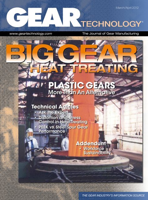
Big <strong>Gear</strong><br />
Heat Treating<br />
Plastic <strong>Gear</strong>s<br />
More Than An Alternative<br />
Technical Articles<br />
• Ask the Expert<br />
• Distortion and Stress<br />
Control in Heat Treating<br />
• PEEK vs. Steel Spur <strong>Gear</strong><br />
Performance<br />
Addendum<br />
• Workforce<br />
Sustainability<br />
THE GEAR INDUSTRY’S INFORMATION SOURCE
Long spline and<br />
gear shaft hobbing<br />
The Bourn & Koch 400H CNC horizontal hobbing<br />
machine is a 7-axis CNC machine that can hob spur<br />
gears, helical gears, splines and threads on cylindrical<br />
blanks or shafts.<br />
Its powerful, direct drive work spindle and extremely<br />
stable, steel-polymer composite components make it<br />
ideal for manufacturing large and heavy shaft parts up<br />
to 406 mm in diameter and 6.4 module. Shaft lengths<br />
up to 76” or longer can be processed by the extended<br />
bed versions.<br />
All axes’ movements are supported by high-precision<br />
ball screws and linear roller ways, resulting in very fast<br />
setups and precise part machining. The through-hole,<br />
work spindle drive allows clamping of shaft parts that<br />
exceed the actual work area limitations.<br />
See us in<br />
booths<br />
N 6924 and<br />
W 2232!<br />
Phone: 847-649-1450<br />
5200 Prairie Stone Pkwy. • Ste. 100 • Hoffman Estates • IL 60192
A dual tool setup allows for several gearings on one<br />
shaft or rough and fi nish cutting on one spindle, and<br />
it can hob wet or dry. Machine length extensions are<br />
also available. Learn more at our website or call us to<br />
discuss your application.<br />
Email: sales@star-su.com
March/April 2012<br />
C O N T E N T S<br />
FEATURES<br />
33 The Plastic <strong>Gear</strong> Pay-Off<br />
The plastic gear market is strong—<br />
and growing.<br />
43 Manufacturer’s Guide to Heat<br />
Treating Large <strong>Gear</strong>s<br />
The unique challenges of heat<br />
treating large gears.<br />
TECHNICAL ARTICLES<br />
29 Ask the Expert<br />
New this issue: Industry experts answer<br />
your questions on all things gearing.<br />
50 Controlling <strong>Gear</strong> Distortion and Residual<br />
Stresses During Induction Hardening in<br />
Loaded Spur <strong>Gear</strong>s<br />
<strong>Gear</strong> distortion, residual stresses controlled with<br />
spray nozzle configuration designed to quench<br />
gear surfaces with different cooling rates.<br />
58 Relative Performance of Spur <strong>Gear</strong>s<br />
Manufactured from Steel and PEEK<br />
Test data compared, contrasted to determine<br />
performance of steel-plastic and plastic-plastic<br />
gear combinations.<br />
Photos courtesy of Metlab<br />
Vol. 29, No. 2 GEAR TECHNOLOGY, The Journal of <strong>Gear</strong> Manufacturing (ISSN 0743-6858) is published monthly, except in February, April, July and December by Randall Publications LLC,<br />
1840 Jarvis Avenue, Elk Grove Village, IL 60007, (847) 437-6604. Cover price $7.00 U.S. Periodical postage paid at Arlington Heights, IL, and at additional mailing office (USPS No. 749-290). Randall<br />
Publications makes every effort to ensure that the processes described in GEAR TECHNOLOGY conform to sound engineering practice. Neither the authors nor the publisher can be held responsible for injuries<br />
sustained while following the procedures described. Postmaster: Send address changes to GEAR TECHNOLOGY, The Journal of <strong>Gear</strong> Manufacturing, 1840 Jarvis Avenue, Elk Grove Village, IL, 60007. Contents<br />
copyrighted ©2012 by RANDALL PUBLICATIONS LLC. No part of this publication may be reproduced or transmitted in any form or by any means, electronic or mechanical, including photocopying, recording,<br />
or by any information storage and retrieval system, without permission in writing from the publisher. Contents of ads are subject to Publisher’s approval. Canadian Agreement No. 40038760.<br />
2<br />
GEARTECHNOLOGY March/April 2012 www.geartechnology.com
Customers Say it Best<br />
“To remain competitive in today’s gear<br />
market, manufacturers must upgrade<br />
technology to increase efficiencies<br />
and productivity. Giuliante Machine<br />
Tool, Inc. has done that with the<br />
purchase of a NILES ZE 400 <strong>Gear</strong><br />
Profile Grinding Machine<br />
The Niles ZE 400 has proven to<br />
be a very flexible machine which<br />
grinds internal and external gears<br />
efficiently and at very high quality<br />
levels. On-board inspection and<br />
multi-wheel grinding configurations<br />
have helped slash cycle times on several<br />
projects. The intuitive, conversational control<br />
makes learning the machine easy.<br />
The Niles ZE 400 has allowed us to position ourselves<br />
among today’s leading gear manufacturers.”<br />
Giuliante Machine Tool, Inc. is happy to celebrate its 34th anniversary and relocation to a<br />
30,000 square foot state-of-the-art facility in Peekskill, NY. Visit them at www.gmtgear.com.<br />
The testimony of our customers reflects our mission. Ninety six of every one hundred KAPP<br />
and NILES machines delivered in North America since 1980 are still generating profits for our<br />
customers today. When you purchase a KAPP or NILES machine, you get a commitment for<br />
support that does not expire.<br />
G e a r e d t o m a k e t h i n g s m o v e .<br />
KAPP Technologies<br />
2870 Wilderness Place Boulder, CO 80301<br />
Phone: (303) 447-1130 Fax: (303) 447-1131<br />
www.kapp-usa.com info@kapp-usa.com
March/April 2012<br />
departments<br />
9 Publisher’s Page<br />
Report from India<br />
C O N T E N T S<br />
11 Products<br />
Synergy 2000 software boosts productivity<br />
67 Industry News<br />
The latest in equipment and other industry<br />
offerings<br />
74 Calendar<br />
Westec 2012, other venues of note<br />
76 Subscriptions<br />
Sign up or renew today.<br />
77 Ad Index<br />
Every advertiser in this issue<br />
78 Classifieds<br />
Our products and services marketplace<br />
80 Addendum<br />
Workforce Sustainability<br />
ON L I N E<br />
www.geartechnology.com<br />
• E-MAIL NEWSLETTER<br />
Sign up for our NEW monthly e-mail newsletter<br />
with exclusive gear-related articles and content<br />
at www.geartechnology.com/newsletter<br />
PTE®<br />
powertransmissionengineering<br />
www.powertransmission.com<br />
• Power Transmission Engineering<br />
Sign up for a free subscription.<br />
• NEWS<br />
The latest products, industry news and calendar items.<br />
• BUYERS GUIDE<br />
Search for power transmission products and services and<br />
communicate with the industry's leading suppliers<br />
4<br />
GEARTECHNOLOGY March/April 2012 www.geartechnology.com
Power Skiving – A Milestone<br />
in <strong>Gear</strong> Manufacturing<br />
Discover Power Skiving Live:<br />
IMTS CHICAGO<br />
10-15 September 2012<br />
JIMTOF TOKYO<br />
01-06 November 2012<br />
Member of<br />
Power Skiving – Klingelnberg Presents<br />
its Latest Innovation<br />
The newly developed tool system can be used on Klingelnberg<br />
bevel gear cutting machines. It guarantees a productive,<br />
stable and precise production process, particularly for internal<br />
gears. Klingelnberg enables the breakthrough of Power<br />
Skiving by finally unleashing the full potential of this 100 year<br />
old manufacturing method.<br />
- up to 10 times faster processing times compared to other<br />
manufacturing methods<br />
- smooth flanks with advantageous surface texture<br />
- high gear quality due to precise tooling and dynamic machines<br />
► Learn more about Power Skiving at www.klingelnberg.com<br />
For the US-market please contact: Liebherr <strong>Gear</strong> <strong>Technology</strong>, Inc.<br />
1465 Woodland Drive Saline, Michigan 48176-1259 Phone: 734-429-7225<br />
info.lgt@liebherr.com www.klingelnberg.com
®<br />
When These<br />
Babies Grow Up,<br />
Randall Publications LLC<br />
1840 Jarvis Avenue<br />
Elk Grove Village, IL 60007<br />
847-437-6604<br />
Fax: (847) 437-6618<br />
VOL. 29, NO. 2<br />
They’ll<br />
DIG,<br />
MOVE<br />
& DRIVE.<br />
Our rolled rings are<br />
destined for important work.<br />
So we make sure they’re<br />
strong enough to take on the<br />
most rigorous conditions.<br />
We’re ready<br />
to roll<br />
when you are.<br />
Contact an AJAX<br />
Representative Today<br />
Editorial<br />
Publisher & Editor-in-Chief<br />
Managing Editor<br />
Senior Editor<br />
Associate Editor<br />
Editorial Consultant<br />
Technical Editors<br />
design<br />
Art Director<br />
ADVERTISING<br />
Advertising Sales Manager<br />
Materials Coordinator<br />
CIRCULATION<br />
Circulation Manager<br />
RANDALL STAFF<br />
President<br />
Accounting<br />
www.geartechnology.com<br />
March/April 2012<br />
The Journal of <strong>Gear</strong> Manufacturing<br />
BIG GEAR<br />
HEAT TREATING<br />
PLASTIC GEARS<br />
More Than An Alternative<br />
Michael Goldstein<br />
publisher@geartechnology.com<br />
William R. Stott<br />
wrs@geartechnology.com<br />
Jack McGuinn<br />
jmcguinn@geartechnology.com<br />
Matthew Jaster<br />
mjaster@geartechnology.com<br />
Paul R. Goldstein<br />
William (Bill) Bradley<br />
Robert Errichello<br />
Octave Labath, P.E.<br />
Joseph Mihelick<br />
Charles D. Schultz, P.E.<br />
Robert E. Smith<br />
Dan Thurman<br />
David Ropinski<br />
dropinski@geartechnology.com<br />
Dave Friedman<br />
dave@geartechnology.com<br />
Dorothy Fiandaca<br />
dee@randallpublications.com<br />
Carol Tratar<br />
subscribe@geartechnology.com<br />
Michael Goldstein<br />
Luann Harrold<br />
Technical Articles<br />
• Ask the Expert<br />
• Distortion and Stress<br />
Control in Heat Treating<br />
• PEEK vs. Steel Spur <strong>Gear</strong><br />
Performance<br />
Addendum<br />
• Workforce<br />
Sustainability<br />
Toll Free: 800.727.6333<br />
Phone: 803.684.3133<br />
www.ajaxring.com<br />
THE GEAR INDUSTRY’S INFORMATION SOURCE<br />
Photo courtesy<br />
of Metlab<br />
6<br />
GEARTECHNOLOGY March/April 2012 www.geartechnology.com
SE<br />
GEAR SHAPERS<br />
The Mitsubishi<br />
E Series<br />
FE<br />
GEAR SHAVERS<br />
GE<br />
GEAR HOBBERS<br />
The Truth be Told<br />
E Could Stand For:<br />
Excellence.<br />
Extraordinary.<br />
Extreme, etc...<br />
and one would be forgiven for<br />
thinking so, because these<br />
descriptions certainly represent<br />
the Mitsubishi machines which<br />
contain this letter in their model<br />
name. However, the simple truth is<br />
that the letter E denotes that these<br />
machines are the latest iterations of<br />
the models which carry it. The SE<br />
gear shapers, GE gear hobbers, FE<br />
gear shavers and ZE gear grinders<br />
epitomize the development of the<br />
process technology they have been<br />
designed for and so aptly carry out.<br />
Research and Development is not<br />
just a glib phrase at Mitsubishi; it is a<br />
philosophy that the company stands<br />
by to stay ahead of its competition<br />
and to ensure continuing profitability<br />
and the profitability of its customers.<br />
Yes, E could stand for many things<br />
but with continuous striving for<br />
perfection and intense R & D,<br />
the E simply means it is as good<br />
as it gets. Period.<br />
To personally experience the<br />
world-class performance of the<br />
Mitsubishi E Series of machines<br />
visit mitsubishigearcenter.com<br />
or contact sales 248-669-6136.<br />
Machine Tool Division • <strong>Gear</strong> <strong>Technology</strong> Center<br />
46992 Liberty Drive • Wixom, MI 48393<br />
mitsubishigearcenter.com<br />
ZE<br />
GEAR GRINDERS
P u b l i s h e r ’ s P a g e<br />
Report<br />
from India<br />
Whenever I meet with readers, I find that—without<br />
exception—they express their deep appreciation for <strong>Gear</strong><br />
<strong>Technology</strong> and its educational mission. Time and again<br />
they tell me the impact this <strong>magazine</strong> has had on their<br />
understanding of gear manufacturing and, as a result, on<br />
their careers. I’ve experienced such gratitude especially<br />
when I’ve traveled to <strong>Gear</strong> Expo or the AGMA annual convention.<br />
On my recent trip to India, I was delighted to find an<br />
appreciation just as profound among our Indian subscribers,<br />
many of whom have read our <strong>magazine</strong> for decades.<br />
<strong>Gear</strong> <strong>Technology</strong> has developed an outstanding reputation<br />
as the leading publication in the gear industry, everywhere<br />
in the world. Those of you who travel for business<br />
have no doubt seen it on desktops, on shop floors and<br />
in break rooms in virtually every country where gears<br />
are made. But in India, like most places, our reach has<br />
been limited by the fact that paid subscriptions have been<br />
required in order to receive a paper copy. Most of the<br />
Indian subscribers who have known us for so long are the<br />
department managers and CEOs of gear companies who<br />
were willing to pay for those subscriptions.<br />
But for India, at least, that all changed with my recent<br />
trip. I traveled to Mumbai to exhibit at the IPTEX 2012<br />
show and to launch <strong>Gear</strong> <strong>Technology</strong> India.<br />
This new <strong>magazine</strong> now gives us the opportunity to<br />
expand the reach of our educational mission—not only<br />
geographically, but also in terms of subject matter. Now our<br />
top-notch technical information has a greater reach in an<br />
important industrial marketplace. In addition to gears and<br />
gear manufacturing, <strong>Gear</strong> <strong>Technology</strong> India includes coverage<br />
and technical articles on bearings, motors, couplings,<br />
clutches and other power transmission components, similar<br />
to Power Transmission Engineering.<br />
Having their own industry <strong>magazine</strong> was a big deal over<br />
there. Our Indian partners, Virgo Publications, hung giant<br />
signs promoting the new <strong>magazine</strong> throughout the exhibit<br />
halls. At a formal ceremony before the show started, I was<br />
given the opportunity to introduce the new <strong>magazine</strong>. I<br />
explained how <strong>Gear</strong> <strong>Technology</strong> India would embrace the<br />
educational model that we’ve followed for 27 years, and<br />
I described how the comprehensive body of knowledge<br />
we’ve developed will serve as a vital resource for Indian<br />
industry.<br />
Exhibitors and attendees alike were effusive in their<br />
gratitude for us having brought this type of educational<br />
resource to their marketplace. We signed up thousands of<br />
new subscribers at the show, and I expect many of them<br />
will become long-time readers.<br />
Those of you whose products are sold in India should<br />
take a look at www.geartechnologyindia.com, where you<br />
can see the first issue. <strong>Gear</strong> <strong>Technology</strong> will continue to<br />
go there, but the interest in <strong>Gear</strong> <strong>Technology</strong> India is much<br />
broader, including those readers and advertisers who have<br />
little interest in the gear and power transmission industry<br />
markets outside of India. Not only can this <strong>magazine</strong> give<br />
you a window into the Indian marketplace, but also, it can<br />
give your company a new potential way to reach it.<br />
Besides the successful introduction of our new <strong>magazine</strong>,<br />
IPTEX itself was a big success. In many ways it’s similar<br />
to <strong>Gear</strong> Expo, with about 60 percent of exhibitors representing<br />
suppliers to gear manufacturers, and the remaining<br />
40 percent representing gear and power transmission<br />
product manufacturers. Although the show started slowly,<br />
attendance was strong both the second and third days. The<br />
exhibitors I talked to were extremely satisfied with both the<br />
number and quality of the attendees.<br />
It’s clear to me<br />
also that the gear<br />
industry is taking<br />
the Indian marketplace<br />
quite seriously.<br />
Global exhibitors<br />
flew in the<br />
VPs and top executives<br />
from Europe<br />
and the United<br />
States, in addition<br />
to staffing their<br />
booths with their<br />
Indian sales agents.<br />
My impression is that IPTEX is a show to watch. If<br />
you’re at all interested in the Indian marketplace, you might<br />
consider attending or exhibiting in 2014 (visit www.iptexpo.<br />
com for more information). My personal expectation is<br />
that—with the additional help and promotional venue provided<br />
by <strong>Gear</strong> <strong>Technology</strong> India—the exhibitor and attendance<br />
base of this show could easily double by the next<br />
time around.<br />
All of our readers—whether they’re in India, the U.S.A<br />
or anywhere around the world—can rest assured that we’ll<br />
be there for you as we continue to expand our role as “the<br />
gear industry’s global information source.”<br />
Michael Goldstein,<br />
Publisher & Editor-in-Chief<br />
www.geartechnology.com March/April 2012 GEARTECHNOLOGY 9
Aerospace Precision Inspection & Testing Automotive Quality &<br />
Speed<br />
As an AS 9100 & ISO 9001 Registered<br />
Company, Delta <strong>Gear</strong> provides aircraft<br />
quality gears and machined components<br />
at automotive prices. Since 1964, Delta<br />
<strong>Gear</strong> (formerly Tifco Gage & <strong>Gear</strong>) has<br />
been producing precision parallel-axis<br />
gears. It is our continued passion to<br />
expand our capabilities in high precision<br />
gears, machined components, assemblies<br />
and inspection – giving you the<br />
highest quality, convenience and<br />
on-time delivery.<br />
Our newest addition to the Delta Family<br />
of Companies is Delta Inspection.<br />
Inspired on the understanding that<br />
the industry needs expert abilities for<br />
contract gear inspection services, Delta<br />
Inspection has been introduced to meet<br />
your gear inspection and testing needs.<br />
Our abilities range from gear inspection<br />
up to 39 inches (1 meter) to prismatic<br />
inspection of machined components,<br />
roundness, laser guided concentricity<br />
analysis, surface testing, material testing,<br />
Nadcap certified magnetic particle<br />
inspection, nital etch and much more.<br />
Delta Family Of Companies<br />
1-734-261-6400 | 1-734-261-0909 www.deltainspection.com<br />
Fax | ISO 9001 & AS 9100 Registered<br />
Delta Research is a world class provider<br />
of CNC 3-Axis, 4-Axis and 5-Axis<br />
precision machining, jig grinding,<br />
cylindrical grinding, precision gears and<br />
complete assemblies for automotive,<br />
aerospace and industrial applications.<br />
From complete automotive prototype<br />
transmissions or components, to<br />
defense, to aerospace machining and<br />
assembly,, you will be impressed by our<br />
capabilities and commitment to quality.<br />
1-734-525-8000 | 1-734-525-8400 Fax | ISO 9001 & AS 9100 Registered<br />
www.delta-gear.com www.deltainspection.co www.deltaresearch.com
P R O D U C T<br />
N E W S<br />
Quality Assurance Gains on<br />
the Manufacturing Floor<br />
Zontec’s SPC Software<br />
Increases Productivity for <strong>Gear</strong><br />
Manufacturer<br />
In today’s increasingly competitive<br />
landscape, companies that do not pay<br />
attention to their quality data do so at<br />
their own peril, according to Danei<br />
Edelen, marketing manager at Zontec<br />
Inc. “Capturing and utilizing quality<br />
data can reduce scrap, reduce work,<br />
increase user productivity, assist with<br />
tool lifecycle management and help<br />
generate new business.”<br />
Zontec Inc., located in Cincinnati,<br />
Ohio, is an international developer of<br />
Statistical Process Control (SPC) software<br />
solutions. The company recently<br />
updated its Synergy 2000 software to<br />
maximize the users’ access to information.<br />
“These new capabilities are<br />
focused on running a business more<br />
efficiently and effectively,” says<br />
Warren Ha, Zontec president. “We are<br />
leading the industry by providing superior<br />
functionality so users have multiple<br />
ways to access the wealth of information<br />
available at the click of mouse.”<br />
This includes increasing productivity,<br />
reducing product defects, boosting<br />
production rates and generating<br />
new business. “Synergy 2000 enables<br />
you to fine-tune your business by adding<br />
value at every step in the process.<br />
It’s logically designed with the user in<br />
mind. Therefore, you are able to rapidly<br />
implement a quality solution, saving<br />
you time and money. Your users are<br />
easily able to navigate the system and<br />
utilize numerous ways to input data<br />
efficiently. Data is passed through SPC<br />
calculations, so that real-time charting<br />
and reporting is constantly available for<br />
decision-making,” Edelen says.<br />
Synergy 2000 is designed in three<br />
levels: engineer, manager and operator.<br />
This means that as operators are entering<br />
data, managers and engineers can<br />
be monitoring and reviewing this data<br />
in real-time. If a process goes out-ofspecification,<br />
the appropriate people<br />
can view this information immediately<br />
on their screens and automatic e-mail<br />
notifications are sent out as well. With<br />
the tools available, a customer can integrate<br />
Synergy 2000 with any system in<br />
your enterprise. With company-wide<br />
monitoring in place, key individuals,<br />
regardless of location, can supervise<br />
production to meet company objectives.<br />
Also, if your industry requires<br />
secure controls over your quality data,<br />
Synergy 2000 has such security measures<br />
available.<br />
United <strong>Gear</strong> Gains Business with<br />
Synergy 2000. When Douglas Winfrey,<br />
director of quality, started at United<br />
<strong>Gear</strong> and Assembly, the Synergy software<br />
had already been purchased, but<br />
was not fully utilized. “I inherited<br />
Synergy, and I enforced it,” Winfrey<br />
says. He immediately saw the benefits<br />
of utilizing the quality assurance software.<br />
”The real issue was that we were<br />
collecting all of this data, but not looking<br />
at the data. Synergy gave us a way to<br />
easily pull up the data and act on what<br />
we are seeing; it also gave us the ability<br />
to access the data anywhere in the<br />
world, including our customer sites.”<br />
United <strong>Gear</strong> has been in business for<br />
50 years. During that time, they have<br />
evolved from a family-owned business<br />
into a multi-million dollar company<br />
and a core supplier of precision gears,<br />
shafts and related assemblies to companies<br />
in the automotive, agriculture,<br />
forestry, construction, mining, marine<br />
and rail industries. “We are now expanding<br />
our presence along with our parent<br />
company, United Stars, based out of<br />
Beloit, Wisconsin, into the Pacific Rim<br />
and recently opened an office in China,”<br />
continued<br />
www.geartechnology.com March/April 2012 GEARTECHNOLOGY 11
P R O D U C T<br />
N E W S<br />
Winfrey says.<br />
Once United <strong>Gear</strong> began using<br />
Synergy, they found that the software<br />
made it easy for individuals without a<br />
statistics background to create charts<br />
on their machines, setup to receive<br />
notifications, reduce the number of<br />
errors and assist the inexperienced<br />
operator in understanding the process<br />
clearly. “It’s a very good teaching tool<br />
to be able to explain with visuals to<br />
describe where the process is running<br />
at and where we want to be,” Winfrey<br />
says. “Within seconds, we can call up<br />
a part number on a machine and know<br />
what’s going on with that machine or<br />
the current production run.”<br />
“Since implementing Synergy, the<br />
reduction in paperwork is huge. Before<br />
every entry took us about 3½ minutes<br />
per sample size and now it takes us less<br />
than 30 seconds. There are 240 critical<br />
characteristics we could be measuring<br />
at any given time. Using Synergy has<br />
saved us about 12 man-hours per day,”<br />
Winfrey adds.<br />
One of the benefits United <strong>Gear</strong> has<br />
experienced is that they came to a better<br />
understanding of their machines<br />
and their capabilities. “Through data<br />
gathering, charting and analysis, we<br />
can analyze data on every product produced<br />
in a particular machine. We can<br />
get to the root cause, whether it is the<br />
people, the process or the machine,”<br />
Winfrey says. “We run product on several<br />
machines; with Synergy we can<br />
compare a machine’s capability, which<br />
gives us the least variation and best<br />
product. We can see inconsistencies<br />
and make systematic changes across<br />
the entire process; we can see data<br />
points for all products, regardless of<br />
machine and resolve inconsistencies<br />
for all processes.”<br />
Synergy also gives United <strong>Gear</strong> the<br />
ability to effectively manage the lifecycle<br />
of its tools. Through the use of<br />
Run Charts and other Synergy tools<br />
they can determine tool life and predict<br />
how many parts can run before needing<br />
to make adjustments or change out the<br />
tool. “We can budget our tool life management<br />
more accurately and effectively<br />
based on this data,” says Winfrey.<br />
“Synergy can show us if a particular<br />
machine can’t produce a particular<br />
product in a specific tolerance range.<br />
This data can then be used to justify<br />
procurement of new equipment.”<br />
Additionally, Synergy has helped<br />
United <strong>Gear</strong> with their Six Sigma and<br />
continuous improvement initiatives.<br />
“In the aspects of our business where<br />
we are using Synergy, we have seen<br />
our PPM (parts per million) decrease,”<br />
Winfrey says. “On average, we have<br />
reduced our non-conformities by 20<br />
percent. We also have a very low scrap<br />
rate in those applications.”<br />
Winfrey says they use Synergy for<br />
new business development. “I have<br />
been in meetings at the customer’s<br />
location where we are discussing a new<br />
product. Synergy gives us the ability<br />
12<br />
GEARTECHNOLOGY March/April 2012 www.geartechnology.com
P R O D U C T<br />
N E W S<br />
to log into our server, show them the<br />
exact machine that would be used to<br />
produce the new product, what tolerance<br />
the machine is currently running<br />
and the capability history of that<br />
machine,” Winfrey said. “This type of<br />
information shows the customer what<br />
they need to see before moving forward.<br />
Synergy provides us that edge to<br />
win the business.”<br />
The Future of SPC. From a quality<br />
management perspective, Zontec has<br />
developed a solution that fully supports<br />
mobile technology and cloud computing<br />
architecture. Zontec’s Synergy 3000<br />
SPC software was designed from the<br />
outset so that users can gather, organize,<br />
analyze and report on the huge data sets<br />
dictated by real-time, statistical process<br />
control over the Internet from highly<br />
dispersed global locations. “We see the<br />
use of cloud computing and mobile<br />
technology particularly applicable as<br />
it relates to managing your suppliers,”<br />
Edelen says. “With Synergy 3000, suppliers<br />
have access to customer standard<br />
operating procedures, engineering drawings<br />
and contract specifications during<br />
their production runs. Suppliers enjoy<br />
data collection and gage interfacing<br />
through the browser in addition to charting,<br />
process monitoring, real-time feedback<br />
and reporting.”<br />
For more information:<br />
United <strong>Gear</strong> and Assembly<br />
1700 Livingstone Road<br />
Hudson, WI. 54016-9365<br />
Phone: (715) 386-5867<br />
www.ugaco.com<br />
Zontec Inc.<br />
1389 Kemper Meadow Dr.<br />
Cincinnati, OH 45240<br />
Phone: (513) 648-9695<br />
www.zontec-spc.com<br />
GWJ<br />
UpdATES<br />
<strong>Gear</strong>Engineer<br />
Software<br />
GWJ <strong>Technology</strong> GmbH, headquartered<br />
in Braunschweig, Germany,<br />
recently introduced a new version of<br />
its <strong>Gear</strong>Engineer software. The version<br />
comes with a variety of new features<br />
and functions including profile and<br />
flank modifications as well as the tooth<br />
contact analysis (TCA). Additionally,<br />
the user can calculate the load capacity<br />
of bevel gears according to ISO<br />
10300. The <strong>Gear</strong>Engineer is a software<br />
continued<br />
www.geartechnology.com March/April 2012 GEARTECHNOLOGY 13
P R O D U C T<br />
N E W S<br />
application for the calculation of the<br />
accurate 3-D gear tooth form of cylindrical<br />
and bevel gears based on the<br />
mathematical simulation of the manufacturing<br />
process.<br />
The accurate gear tooth form is the<br />
basis for manufacturing gears, in conjunction<br />
with multi-axis machining<br />
centers or non-cutting manufacturing<br />
processes. The standard exchange formats<br />
STEP and IGES serve as a neutral<br />
file format to transfer the accurate<br />
tooth geometry. The geometry data can<br />
be used for further developmental purposes,<br />
for example for a universal manufacturing<br />
or used as 3-D nominal data<br />
for additional measurements. Profile<br />
and flank modifications were now<br />
added to the <strong>Gear</strong>Engineer calculation<br />
module for cylindrical gears. A dropdown<br />
menu allows the user to select<br />
linear and circular tip or root relief as<br />
well as symmetric profile crowning.<br />
In addition to the profile modifications,<br />
the gear flank modifications lead<br />
crowning and profile crowning are<br />
available. The user can decide between<br />
symmetric and asymmetric lead crowning.<br />
End relief can be applied to both<br />
tooth ends or to the left or right end of<br />
the tooth.<br />
Additionally, the <strong>Gear</strong>Engineer now<br />
includes TCA to calculate and visualize<br />
the contact pattern of gears. After<br />
completion of the gear calculation,<br />
the tooth contact analysis allows the<br />
calculation of the size and position of<br />
the contact pattern without load. The<br />
contact pattern is visually displayed<br />
in the 3-D model. The analysis is possible<br />
for external and internal spur and<br />
helical gears and helical, straight and<br />
Zyklo-Palloid spiral bevel gears. The<br />
engineer can optimize spur and bevel<br />
gears before the manufacturing begins.<br />
Deviations and displacements from the<br />
ideal position are taken into account.<br />
The new <strong>Gear</strong>Engineer version provides<br />
the possibility to determine the<br />
14<br />
GEARTECHNOLOGY March/April 2012 www.geartechnology.com
P R O D U C T<br />
N E W S<br />
load capacity of straight, helical and<br />
spiral bevel gears according to ISO<br />
10300.<br />
For more information:<br />
GWJ <strong>Technology</strong> GmbH<br />
Rebenring 13<br />
38106 Braunschweig<br />
Germany<br />
Phone: +(49) 531 129 399<br />
www.gwj.de<br />
Birchwood<br />
Casey<br />
Improves Black<br />
Oxide Coating<br />
light metals, such as aluminum, brass<br />
and zinc without discoloring the metal.<br />
Birchwood Casey’s Oxyprime primer/surface<br />
prep serves as an activator<br />
and primer to make the metal surface<br />
more receptive to the subsequent coloring<br />
or blackening operation. Tool steels<br />
and heat treated parts must be activated<br />
and/or de-scaled by means of a surface<br />
continued<br />
Metal surface cleaners and conditioners<br />
from Birchwood Casey improve<br />
black oxide coating and other metal<br />
finishing processes. Available in a<br />
range of biodegradable liquid cleaners<br />
and mild acid conditioners, they<br />
provide the just-right surface preparation<br />
to achieve top quality finishes.<br />
For example, most machined and fabricated<br />
metal components carry cutting<br />
oils or coolants that coat the metal<br />
surface and collect in threaded holes<br />
and recessed areas. Heat treat scale<br />
and light rust are also commonly seen.<br />
These surface soils must be completely<br />
removed prior to blackening or coating<br />
in order to achieve high quality results.<br />
These conditions are easily handled by<br />
choosing the right surface preparation<br />
from the following products:<br />
Birchwood Casey’s Presto Kleen<br />
powdered cleaner and Safe Scrub<br />
ST biodegradable liquid cleaner are<br />
designed for medium- to heavy-duty<br />
soak tank cleaning of iron and steel<br />
parts. These products mix easily with<br />
water and operate at temperatures of<br />
120–180 degrees F to quickly lift oily<br />
residues from the metal surface and<br />
hold them in suspension. Their unique<br />
blend of detergents make them freerinsing<br />
in cold water, giving them the<br />
ability to produce waterbreak-free surfaces<br />
that are receptive to subsequent<br />
coating operations. Also available is<br />
Safe Scrub M for effective cleaning of<br />
www.geartechnology.com March/April 2012 GEARTECHNOLOGY 15
P R O D U C T<br />
N E W S<br />
conditioner prior to subsequent finishing<br />
operations. The Oxyprime solution<br />
provides that function for black<br />
oxide, cold blackeners and antique finishing.<br />
It provides a mild acid surface<br />
conditioning to ensure uniform adhesion<br />
across the part, without the risk<br />
of hydrogen embrittlement. In some<br />
cases, the Oxyprime descaling operation<br />
can also be used in conjunction<br />
with ultrasonic rinsing to remove all<br />
traces of surface particulates, thereby<br />
producing a white-glove clean black<br />
oxide finish.<br />
Oxyprime is available in powdered<br />
and liquid concentrate for a variety of<br />
finishing jobs, including activation,<br />
oxide removal or the formation of a<br />
base coat for subsequent Tru Tempo<br />
low temperature black oxide finishing.<br />
<strong>Gear</strong> Solutions From Drake<br />
All Drake <strong>Gear</strong> Machines are shipped with the<br />
latest CNC controls, <strong>Gear</strong> Smart programming,<br />
field support and guaranteed performance.<br />
GS:G 2 <strong>Gear</strong> Grinders<br />
• Grind 25mm to 350mm tip diameter<br />
• CNC contour diamond roll dressing<br />
• CNC direct drive torque motor work index<br />
• DIN 2-3 quality capable<br />
• User-friendly software<br />
GS:TE-LM Worm Grinders<br />
• Part lengths up to 2m<br />
• Diameters up to 650mm<br />
• Auto load available<br />
• ZK, ZI, ZN, ZA to DIN 1-2 quality capable<br />
GS:RM Rack Mills<br />
• Auto load in a cell<br />
• No pits or platforms<br />
• 10-minute cutter change<br />
• Compare to broaching<br />
GS:H <strong>Gear</strong> Hobbers<br />
• Up to 1800mm diameter<br />
• Auto load & probe<br />
• Power helix<br />
CS:R Control System Renewal<br />
• New CNC for “brain dead” good iron<br />
• <strong>Gear</strong> grinders, hobbing machines,<br />
thread and rack milling machines<br />
• Work done on your floor<br />
• Only 2 weeks downtime<br />
All metal cleaners and surface conditioners<br />
from Birchwood Casey are<br />
available in container sizes for small<br />
and large scale finishing operations<br />
and for use in various types of process<br />
lines, such as black oxide, phosphatizing<br />
and other metal coating systems.<br />
Complete technical information for<br />
each Birchwood Casey product is available<br />
online. A technical service expert<br />
is also available by phone to determine<br />
which metal cleaner and surface conditioner<br />
is best for a specific application.<br />
For more information:<br />
Birchwood Laboratories, Inc.<br />
7900 Fuller Road<br />
Eden Prairie, MN 55344<br />
Phone: (800) 328-6156<br />
www.birchwoodlaboratories.com<br />
Mitutoyo<br />
Releases Hand-<br />
Held Measurement<br />
Tool<br />
Mitutoyo America Corporation<br />
announces the availability of its new,<br />
High-Accuracy Digimatic Digital<br />
Micrometer, the first micrometer to<br />
offer 0.1 µm resolution measurement.<br />
Now, high-accuracy measurement can<br />
be had in a convenient, hand-held tool.<br />
The Digimatic Micrometer utilizes the<br />
Drake <strong>Gear</strong> Machines<br />
Represented in North America by:<br />
Precision Machines for Threads & <strong>Gear</strong>s<br />
Drake Manufacturing Services Co.<br />
Tel: 330-847-7291<br />
info@drakemfg.com<br />
www.drakemfg.com<br />
Koepfer America LLC<br />
Tel: 847-931-4121<br />
sales@koepferamerica.com<br />
www.koepferamerica.com<br />
16<br />
GEARTECHNOLOGY March/April 2012 www.geartechnology.com<br />
DRAK-454<strong>Gear</strong><strong>Technology</strong>Ad-US.indd 1<br />
2/28/12 11:24 AM
P R O D U C T<br />
N E W S<br />
Absolute rotary sensor (patent pending)<br />
manufactured utilizing Mitutoyo’s<br />
own high precision screw machining<br />
technology. This sensor reduces instrument<br />
error to ± 0.5 µm to deliver high<br />
accuracy with no trade-off in operability.<br />
The Absolute system eliminates<br />
the need to reset the origin each time<br />
power is turned on thus enabling measurement<br />
immediately upon start-up.<br />
In addition, the measurement origin<br />
can be preset to any value within the<br />
display range to reduce set-up time and<br />
improve repeatability. The display can<br />
be zeroed at any position, making comparison<br />
measurement easier. Display<br />
resolution can be switched to 0.5 µm<br />
if 0.1 µm measurement is not required.<br />
The Digimatic Micrometer features<br />
an extremely rigid frame for stable<br />
measurement while a constant-force<br />
barrel/spindle mechanism eliminates<br />
the possibility of overspeed errors.<br />
Transference of body heat to the instrument<br />
is reduced by use of a heat shield<br />
(removable), minimizing errors attributable<br />
to thermal expansion while<br />
handheld measurements are performed.<br />
Additionally, it supports output to<br />
measurement data applications such as<br />
MeasurLink, Mitutoyo’s proprietary<br />
statistical-processing and process-control<br />
program which performs statistical<br />
analysis and provides real-time display<br />
of measurement results for SPC applications.<br />
The program can also be linked to<br />
a higher-level network environment for<br />
enterprise-wide functionality.<br />
For more information:<br />
Mitutoyo America Corporation<br />
965 Corporate Blvd.<br />
Aurora, IL 60502<br />
Phone: (630) 820-9666<br />
www.mitutoyo.com<br />
FORGED<br />
NET and<br />
NEAR-NET<br />
GEARS<br />
• Save Time and Money<br />
• Dedicated State-of-The-Art<br />
Net and Near-Net <strong>Gear</strong><br />
Manufacturing Facility<br />
• .008 - .060 Stock<br />
Allowance on <strong>Gear</strong> Flanks<br />
• ISO 9001:2008<br />
• TS 16949:2009<br />
Presrite Corporation<br />
Phone: (216) 441-5990<br />
www.presrite.com<br />
© 2 0 1 1 , P r e s r i t e C o r p o r a t i o n<br />
www.geartechnology.com March/April 2012 GEARTECHNOLOGY 17<br />
PRS-029 <strong>Gear</strong>Ad-<strong>Gear</strong>Tech2.indd 1<br />
12/22/11 9:50 AM
P R O D U C T<br />
Micro<br />
Precision<br />
<strong>Gear</strong><br />
Utilizes Holroyd<br />
Grinder<br />
N E W S<br />
Holroyd Precision, a division of the<br />
Precision Technologies Group, has<br />
recently completed a customer satisfaction<br />
survey with major customer Micro<br />
Precision <strong>Gear</strong> <strong>Technology</strong> Limited<br />
of Hemel Hempstead, Hertfordshire.<br />
Having supplied Micro Precision<br />
<strong>Gear</strong> <strong>Technology</strong> Limited with a<br />
GTG2 model gear and thread grinder<br />
some eight years ago, the Milnrow,<br />
Lancashire operation canvassed Micro<br />
Precision <strong>Gear</strong> <strong>Technology</strong>’s Phil<br />
McIntyre, section leader, gear grinding,<br />
for feedback on living with the<br />
machine on a daily basis.<br />
The GTG2 machine in question<br />
is used by Micro Precision <strong>Gear</strong><br />
<strong>Technology</strong> Limited in the manufacture<br />
of worms, helical and spur gears while<br />
Holroyd is also currently working with<br />
the company to develop bespoke worm<br />
software for the machine. The machine<br />
is used to grind worms from 15 mm to<br />
250 mm in diameter with a smallest gear<br />
of 0.6 module right up to the largest of<br />
4 module. According to McIntyre, “The<br />
machine has been extremely reliable.<br />
It’s incredibly accurate and will run all<br />
day for six days a week. Its flexibility is<br />
another major plus. And, just as importantly,<br />
it’s also remarkably easy to use<br />
and program with a new operator usually<br />
able to get the hang of things within<br />
just two weeks.”<br />
The Holroyd GTG2 is an extremely<br />
versatile, multi-purpose grinding<br />
system for the batch or volume production<br />
of precision spur and helical<br />
gears, worms, screws and rotors.<br />
Sophisticated yet simple to operate, the<br />
machine combines rigidity with high<br />
power for either CBN or conventional<br />
deep grinding operations with classleading<br />
levels of accuracy and finish.<br />
Fast setups optimize productivity while<br />
the advanced and highly integrated<br />
user interface facilitates the production<br />
of a finished component from the initial<br />
design drawing. In addition to the<br />
production of all types of spur, helical<br />
and worm gears, the machine can also<br />
be configured for grinding ball-screws,<br />
18<br />
GEARTECHNOLOGY March/April 2012 www.geartechnology.com
P R O D U C T<br />
N E W S<br />
small compressor rotors, internal gears<br />
and threads.<br />
Typical applications include highperformance<br />
aerospace, automotive,<br />
precision motion, low noise and master<br />
gears. An on-board 3-D scanning<br />
probe maximizes accuracy using profile<br />
correction feedback and improves<br />
productivity by removing the need for<br />
off-machine profile inspection.<br />
For more information:<br />
Micro Precision Limited<br />
Duxons Turn<br />
Hemel Hempstead<br />
Herts HP2 4SB<br />
United Kingdom<br />
Phone: +(44) 1422 241027<br />
www.microprecision.co.uk<br />
Holroyd Precision<br />
Harbor Lane North<br />
Milnrow, Rochdale<br />
Lancashire OL163LQ<br />
United Kingdom<br />
Phone: +(44) 1706 526 590<br />
www.ptgltd.com<br />
Grieve<br />
Offers High<br />
Temperature<br />
Inert Atmosphere<br />
cABInet Oven<br />
No. 855 is a 1,250-degree Fahrenheit<br />
electrically-heated, inert atmosphere<br />
cabinet oven from Grieve, currently<br />
used for heat treating at the customer’s<br />
facility. Workspace dimensions on this<br />
oven measure 38" × 26" × 38". 40 kW<br />
are installed in Incoloy-sheathed tubular<br />
elements to heat the oven chamber,<br />
while a 1,500 CFM, 1½ HP re-circulating<br />
blower provides horizontal airflow<br />
to the workload. This Grieve cabinet<br />
oven features 10" insulated walls comprising<br />
2" of 1,900-degree F block and<br />
8" of 10 lb/cf density rockwool insulation,<br />
Type 304, 2B finish stainless steel<br />
interior with continuously backwelded<br />
seams, plus inner and outer door<br />
gaskets with the inner gasket sealing<br />
directly against the door plug while the<br />
outer gasket seals directly against the<br />
face of the oven. Full inert atmosphere<br />
construction further includes a pressure<br />
regulator, flow meter, pressure gauge,<br />
internal high-temperature gasket, all<br />
welded expansion connection in door-<br />
continued<br />
www.geartechnology.com March/April 2012 GEARTECHNOLOGY 19
P R O D U C T<br />
way throat, air jacket on inner oven for<br />
cooling, ½" thick silicone rubber atmosphere<br />
seal, blower shaft seal, positive<br />
latching door hardware, adjustable<br />
offset door hinges, outlet with pressure<br />
relief, interior seams welded gastight<br />
and all wall penetrations fitted<br />
with compression fittings. A 325 CFM<br />
blower pulls air through the air jacket<br />
on the inner oven for cooling. Controls<br />
on No. 855 include a special heating/<br />
cooling temperature controller to control<br />
heating elements for heating and<br />
modulating damper on cooling blower<br />
for cooling. The oven also has an SCR<br />
power controller and circular chart<br />
recorder onboard.<br />
For more information:<br />
The Grieve Corporation<br />
500 Hart Road<br />
Round Lake, IL 60073<br />
Phone: (847) 546-8225<br />
sales@grievecorp.com<br />
www.grievecorp.com<br />
N E W S<br />
LMC<br />
Releases Chandox<br />
SE Series Chucks<br />
Chandox SE Series Super Thin<br />
Chucks are now available from LMC<br />
Workholding. These chucks are well<br />
suited for holding workpieces for gaging<br />
and metrology applications. The<br />
chuck knob is rotated directly for gripping<br />
and loosening without the need<br />
for a handle. The SE Series chuck bodies<br />
are made of durable steel. Jaws<br />
are reversible to grip various<br />
sizes more conveniently;<br />
small sizes of 0.8 mm<br />
can be gripped with<br />
2" chucks. LMC<br />
Workholding engineers<br />
and manufactures<br />
high quality<br />
chucks and cylinders<br />
along with special<br />
workholding devices,<br />
including aluminum<br />
wheel chucks, high<br />
volume machining power<br />
chucks and fixtures, standard<br />
and special hydraulic steady rests,<br />
special application and large cast type<br />
manual steady rests, Stiefelmayer specialty<br />
clamping tools, and Chandox<br />
brand chucks and cylinders. LMC<br />
Workholding will be exhibiting at<br />
IMTS 2012 in Booth No. W–1314.<br />
For more information:<br />
LMC Workholding<br />
1200 West Linden Avenue<br />
Logansport, IN 46947<br />
Phone: (574) 735-0225<br />
www.lmcworkholding.com<br />
MAE Press <strong>Technology</strong><br />
Serves Diverse Markets<br />
During the upcoming AISTech show, May 7-10<br />
in Atlanta, MAE Maschinen-und Apparatebau<br />
Götzen GmbH (Erkrath, Germany) will<br />
display its various press technologies<br />
for the iron and steel industry<br />
and related business sectors in Booth<br />
1536. MAE recently announced<br />
its formation of a partnership with<br />
American Wera here for representation<br />
throughout North America. In<br />
the last decades, MAE has developed<br />
increasingly from a manufacturer of<br />
standard hydraulic presses to specialists<br />
for select niche markets. The company<br />
has established a market position<br />
with products in the fields of straight-<br />
continued<br />
20<br />
GEARTECHNOLOGY March/April 2012 www.geartechnology.com
Ipsen’s ATLAS ® integral quench furnaces are highly engineered, sophisticated machines<br />
that are easy to operate and maintain, all while being extremely cost effective. ATLAS<br />
delivers top quality uniformity through cutting-edge technology and design:<br />
• Intelligent controls, Carb-o-Prof ® , provide you with your very own<br />
electronic metallurgist<br />
• SuperQuench with adjustable oil speed and four 40HP agitators<br />
• Muffle system for uniform temperature control<br />
• Safety – all ATLAS furnaces are water-free for maximum safety<br />
• 30% less gas consumption<br />
• Recon ® burners – single ended recuperated tubes (SERT)<br />
®<br />
The unique HybridCarb ® gassing system from Ipsen is an ultra-efficient gassing system<br />
designed to replace endothermic generators and other gassing systems. Its core strength is<br />
precision gas control. Instead of burning excess gas off, the process gas is reconditioned<br />
and reused, increasing efficiency up to 90%.<br />
Other benefits of HybridCarb include:<br />
• Quick and easy hookup<br />
• Increased carburizing efficiency<br />
• Reduces CO 2<br />
emissions by 90%<br />
• Significantly less expensive to operate than<br />
endogenerators<br />
• Consumes significantly less gas<br />
• Environmentally friendly and cost efficient<br />
• Lowers heat output creating a more comfortable<br />
work enviornment<br />
• Powers up and down at anytime, quickly and easily<br />
For more information please visit www.IpsenUSA.com<br />
www.IpsenUSA.com<br />
SPEED UNIFORMITY EFFICIENCY
P R O D U C T<br />
N E W S<br />
ening machines, hydraulic presses and<br />
assembly machines, serving metals<br />
producers, rail, heavy equipment, energy<br />
and marine markets.<br />
Straightening.MAE has the broadest<br />
portfolio of manual and automatically<br />
controlled straightening machines for<br />
handling round, profiled and complexly<br />
shaped workpieces available worldwide.<br />
Press forces from 15 to 25,000<br />
kN make it possible to straighten workpieces<br />
with lengths from 40 mm to 30<br />
m and weights from 5 g to 20 tons.<br />
Straightening accuracy to 0.01 mm is<br />
possible. In addition to the conventional<br />
bending-straightening method,<br />
MAE also offers peening-straightening<br />
for through-hardened workpieces<br />
and torsion-straightening for twisted<br />
section bars. The MAE straightening<br />
controller for the manual straightening<br />
presses in the S-RH and P-H RH Series<br />
guarantees precise and repeatable metalworking<br />
and does not necessitate specially<br />
trained operators. Measurement<br />
and straightening in one setting ensures<br />
optimal cycle times. The M-AH, ASV<br />
and ASRU Series enable automatic<br />
straightening of small, large and complex<br />
shaped workpieces. The software<br />
of the RICOS straightening controller<br />
is the result of decades of experience<br />
with various applications. Innovative<br />
MAE design ideas are further making<br />
the straightening process increasingly<br />
more powerful and faster. Various<br />
interlinking concepts allow continuous<br />
operation with low manpower requirements.<br />
Hydraulic presses.The broad range<br />
of hydraulic standard presses in the S<br />
and DS Series with C- and O-frames<br />
as well as the four-column presses in<br />
the VS Series are based on a modular<br />
system. By recombining and adapting<br />
the individual modules, MAE finds<br />
an inexpensive, individually optimized<br />
solution with press forces up to 25,000<br />
kN for customer needs. Hydraulic<br />
presses are exposed to considerable<br />
stresses in daily use. With 60 years<br />
of experience, MAE has a reputation<br />
for sturdy dimensioning on all components.<br />
Assembly.Whether you want to<br />
assemble gear parts, rotor shafts or<br />
wheelsets, MAE offers many suitable<br />
solutions. The MAE machine Series S<br />
and M-S with hydraulic or mechanical<br />
servo drive are robust machines<br />
tailored to customer application. The<br />
OPUS controller with flexible software<br />
that can be modified to fulfill customer-specific<br />
requirements guarantees<br />
control and documentation of the entire<br />
assembly process. Our horizontally<br />
acting wheel set presses in the RADS<br />
Series with forces up to 8,000 kN are<br />
the industry choice for mounting and<br />
dismounting wheel sets from railway<br />
vehicles. They stand out primarily for<br />
their innovative underlying concept,<br />
rational interlinking systems and extensive<br />
control functions.<br />
Service. An innovative and highquality<br />
machine is only the basis for<br />
high customer satisfaction. Equally<br />
important for continuous duty with<br />
high availability are quick-response<br />
service from experienced technicians<br />
and spare parts available immediately<br />
from stock. North American<br />
installation and service is provided by<br />
American Wera service technicians in<br />
Ann Arbor, Michigan and Queretaro,<br />
Mexico. Additionally, optimally<br />
staffed service centers at located in<br />
Erkrath, Germany and Beijing, China.<br />
Telephone support and remote diagnostics<br />
onboard the machines usually<br />
allow MAE to correct minor problems<br />
without complication or onsite service.<br />
For more information:<br />
American Wera<br />
4630 Freedom Drive<br />
Ann Arbor, MI 48108<br />
Phone: (734) 973-7800<br />
Fax: (734) 973-3053<br />
joseph@american-wera.com<br />
www.american-wera.com<br />
Iscar<br />
Offers Face<br />
Milling Solution<br />
Helido S890 FSN is a new family of<br />
right-hand indexable face mills with an<br />
88 degree cutting edge angle with eight<br />
helical cutting edges, which can be<br />
used for up to 9 mm depth of cut. The<br />
new family was designed for rough to<br />
semi-finish, high-efficiency face milling,<br />
primarily on cast iron and steel<br />
components. The Helido S890 FSN<br />
face mills are available in a diameter<br />
range of 50 to 160 mm in coarse and<br />
fine pitch configurations. Every cutter<br />
body features coolant holes directed to<br />
continued<br />
22<br />
GEARTECHNOLOGY March/April 2012 www.geartechnology.com
Quality <strong>Gear</strong>s...<br />
Save 20% on<br />
your first order!<br />
( Scan tag or visit link by 8/31/2012 )<br />
www.solaratm.com/gear-technology<br />
Start with Quality Heat Treating!<br />
Vacuum Heat Treating | Vacuum Carburizing<br />
Vacuum Brazing | Vacuum Gas Nitriding
the insert cutting edges, for the most<br />
efficient cooling effect.<br />
The inserts feature an advanced<br />
cutting geometry with positive rake,<br />
that ensures smooth milling with soft<br />
entry to and exit from material. They<br />
are produced mainly from the latest<br />
Iscar Sumo Tec carbide grades, providing<br />
suitable performance and tool life.<br />
The winning combination of effective<br />
geometry, innovative carbide grades<br />
and eight cutting edges, enhances productivity<br />
and reduces operational cutting<br />
costs. The new tools provide a<br />
very attractive solution for face milling<br />
applications regarding price per cutting<br />
edge. The Helido S890 FSN family<br />
is a suitable choice for general milling,<br />
especially in applications requiring<br />
machining close to shoulders or fixture<br />
constraints.<br />
When failure is not an option<br />
Bodycote means precision. Bodycote means quality. Bodycote<br />
means your most vital industrial gas turbine parts will operate at<br />
peak performance without fault every time. Your business depends<br />
on it. Our environment depends on it. Lives depend on it.<br />
With the highest standards and more than 170 accredited facilities<br />
in 27 countries, Bodycote is the world’s leading partner in thermal<br />
processing.<br />
It’s a simple thing, really. We make products stronger to keep your<br />
business safer.<br />
www.bodycote.com/gear<br />
For more information:<br />
Iscar Metals Inc.<br />
300 Westway Place<br />
Arlington, TX 76018-1021<br />
Phone: (817) 258-3200<br />
Fax: (817) 258-3221<br />
www.iscar.com<br />
Ticona<br />
Supports Hi-Lex<br />
Power Lift GATE<br />
Transmission<br />
An innovative transmission from<br />
Hi-Lex America Inc. continues to reliably<br />
and quietly open and close auto-<br />
24<br />
GEARTECHNOLOGY March/April 2012 www.geartechnology.com
P R O D U C T<br />
N E W S<br />
motive lift gates thanks to design and<br />
development assistance from Ticona<br />
Engineering Polymers, which helped<br />
the automotive tier supplier create new<br />
injection molded high-precision plastic<br />
shafts and gears.<br />
“For several years, Hi-Lex customers<br />
have used a two-stage reduction<br />
transmission that relies on precision<br />
steel ball bearings mounted on plastic<br />
shafts and accompanying 2.5-inch<br />
diameter plastic gears to achieve the<br />
desired reduction between the electric<br />
motor and a flexible torsional<br />
cable assembly to lift and close big,<br />
heavy automotive rear lift gates,”<br />
said Fred Eberle, technical engineer<br />
at the Hi-Lex Automotive Center in<br />
Rochester Hills, Michigan. Hi-Lex is a<br />
supplier of automotive electromechanical,<br />
power closure devices and control<br />
cables. “A first generation model<br />
used a powder metal shaft system,<br />
which was subsequently replaced with<br />
a plastic shaft system that provides an<br />
immense improvement in NVH (noise,<br />
vibration and harshness) and makes our<br />
customers very happy.”<br />
With input from Ticona, the<br />
American <strong>Gear</strong> Manufacturers<br />
Association, Ohio State University<br />
<strong>Gear</strong> and Power Transmission<br />
Research Laboratory and gear software<br />
developer Universal Technical<br />
Systems, Hi-Lex optimized and refined<br />
the second generation lift gate transmission<br />
via extensive research and<br />
development and testing. It relies on<br />
first- and second-stage plastic splined<br />
shafts attached to plastic gear wheels<br />
in a gearbox with a rated torque output<br />
capacity of about 12 Newton meters<br />
(106 inch pounds).<br />
“From the outset we knew we want-<br />
continued<br />
TRIUMPH<br />
DISASTER<br />
The difference between triumph and disaster can often be<br />
invisible to the naked eye. That’s why you need absolute<br />
precision in the manufacture of engineering components.<br />
Incorporating Holroyd, Binns & Berry, Crawford Swift, PTG<br />
Heavy Industries and Precision Components, the Precision<br />
Technologies Group is a world leader in the manufacture<br />
PTG. ABSOLUTE PRECISION MAKES ALL THE DIFFERENCE<br />
of milling systems, special purpose machine tools and ultra<br />
precision components for HVAC, aerospace, motor racing,<br />
medical, marine, steel, oil and gas.<br />
In fact, precision’s not just our middle name; it’s our first<br />
name too. Which is why PTG is known, globally, as the first<br />
name in precision.<br />
Part of the CQME<br />
Group of Companies<br />
Holroyd Precision Limited<br />
Tel: +44 (0)1706 526590<br />
Fax: +44 (0)1706 353350<br />
Email: info@holroyd.com<br />
www.holroyd.com<br />
www.geartechnology.com March/April 2012 GEARTECHNOLOGY 25<br />
121x178_PTG_<strong>Gear</strong>_Tech_Ad.indd 1 27/01/2012 12:13
P R O D U C T<br />
N E W S<br />
ed to design the transmission with plastic<br />
gears to reduce cost, weight and<br />
especially, noise,” Eberle said. “We<br />
knew Ticona had the gearing and material<br />
expertise to help Hi-Lex achieve its<br />
business goals.”<br />
To avoid any timely and costly setbacks<br />
during development of the twostage<br />
transmission, Hi-Lex established<br />
a plastic gear team early on that included<br />
Eberle and David Sheridan, senior<br />
design engineer at Ticona. The team<br />
defined, analyzed and highly optimized<br />
the design to take advantage of many<br />
considerations unique to plastic gearing.<br />
These considerations can be significantly<br />
more complex than those<br />
for standard metal gears and they pose<br />
challenging implications for gear and<br />
drive designers.<br />
International VDI Congress<br />
Drivetrain for Vehicles 2012<br />
June 19–20, 2012, Friedrichshafen, Germany<br />
With plenary lectures by:<br />
Gold sponsors:<br />
Dr. Stefan Sommer<br />
ZF Friedrichshafen AG<br />
Mihir Kotecha<br />
GETRAG Corporate<br />
Group<br />
Rolf Najork<br />
Schaeffler Gruppe<br />
Register now!<br />
www.transmission-congress.eu<br />
The most important venue for<br />
transmission experts<br />
Jung June Kim<br />
Hyundai Motor Company<br />
Huge accompanying trade exhibition<br />
Simultaneous translation<br />
Dr. Werner Philipp<br />
Robert Bosch GmbH<br />
Christian Chehab<br />
PSA Peugeot Citroën<br />
Dr. Peter Ottenbruch<br />
ZF Friedrichshafen AG<br />
Dr. Martin Koers<br />
Verband der Automobilindustrie<br />
(VDA)<br />
Organised by VDI Wissensforum | www.transmission-congress.eu<br />
Phone +49 211 6214-201 | Fax +49 211 6214-154<br />
“Although Eberle has extensive<br />
experience and skill in regards to gearing<br />
and drive development, the Ticona/<br />
Hi-Lex gear team took the design<br />
and optimization process to the highest<br />
level of geometry analysis, material<br />
application and plastic gear experience,”<br />
Sheridan said. “Ticona used its<br />
50-plus years of plastic gear experience<br />
to help Hi-Lex develop this high-precision<br />
plastic gear transmission.”<br />
Once the requirements were defined,<br />
the team identified materials for the<br />
gears and shafts that would maintain<br />
the required mechanical properties and<br />
dimensional stability, even at elevated<br />
temperatures. The gear team selected<br />
Ticona grades of Celcon acetal copolymer<br />
(POM) and Celstran long fiber reinforced<br />
plastics (LFRT): Celcon M90, a<br />
general purpose, unreinforced POM that<br />
provides a good balance of toughness<br />
and fatigue strength for the first-stage<br />
gear and shaft, Celcon GC25T, a 25<br />
percent glass-coupled POM that provides<br />
the necessary stiffness and fatigue<br />
strength for the second-stage output gear<br />
and Celstran PA 66-GF50-02, a 50 percent<br />
long glass fiber polyamide 66 with<br />
high strength and stiffness combined<br />
with high heat deflection for the secondstage<br />
output shaft.<br />
“For several years, original equipment<br />
manufacturers have used our<br />
power lift gate transmissions in a variety<br />
of automotive platforms,” Eberle<br />
said. “Not once has a gear broken,<br />
worn out or failed in any of our testing,<br />
even with multiple design lives,<br />
or in service. The gears are nice and<br />
quiet. In fact, they get even quieter at<br />
elevated temperature, exactly like they<br />
were designed to do.” Added Sheridan:<br />
“It’s nice when things work out the<br />
way you expect them to. You know you<br />
have it right when the design behaves<br />
the way the analytical models predicted<br />
it would.”<br />
For more information:<br />
Ticona<br />
8040 Dixie Highway<br />
Florence, KY 41042<br />
Phone: (800) 833-4882<br />
www.ticona.com<br />
26<br />
GEARTECHNOLOGY March/April 2012 www.geartechnology.com
AmerWera-11.4.11 1/13/12 10:10 AM Page 2<br />
A solution for every process challenge...<br />
a single call for every solution.<br />
American Wera is your source for the world’s foremost machine technology. From Scudding ® , to gear honing,<br />
surface grinding, polygon milling, turning and shaft straightening, we deliver practical, cost-effective solutions<br />
from a single machine to a complete system.<br />
Praewema <strong>Gear</strong> Grinding Machines<br />
SynchroFine line of high-performance hard gear<br />
grinding machines for coarse pitch applications.<br />
Form grinding or threaded wheel grinding,<br />
you choose!<br />
MAE-Goetzen GmbH<br />
Shaft straightening<br />
machinery and railroad<br />
Wheelset assembly presses.<br />
Pittler T&S GmbH<br />
Application specific<br />
lathe technology for<br />
single or multi-task<br />
operations from<br />
20mm to 6000 mm.<br />
WERA PROFILATOR GmbH<br />
Praewema Honing Machines<br />
SynchroFine line of highperformance<br />
hard gear honing<br />
machines for critical<br />
gearbox applications.<br />
Patented modular machine designs<br />
for the precise manufacture of gears<br />
and polygons<br />
Diskus Werke<br />
High Accuracy CNC<br />
double disk and<br />
surface grinding<br />
machinery.<br />
Call us...let us show you what we can do for you.<br />
4630 Freedom Drive • Ann Arbor, MI 48108 • 734.973.7800 • fax 734.973.3053 • www.American-Wera.com
Creating Valuable Partnerships Since 1962<br />
Inductoheat, Inc. is committed to finding efficient, effective and economic solutions for your<br />
induction heat treating needs. We continue to embrace break-through technologies and customer<br />
service in all that we do, and look forward to serving the metals and materials industry for 50 more.<br />
Inductoheat, Inc. • Madison Heights, MI. USA<br />
Tel: +1 (248) 585-9393 • www.inductoheat.com
A S K T H E E X P E R T<br />
With this issue <strong>Gear</strong> <strong>Technology</strong> introduces what will be a continuing<br />
feature accepting and addressing reader questions on all things gearing,<br />
i.e.—Ask the Expert.<br />
Here’s how it works: Have a standards question? Design query? How<br />
about a backlash or tooth profile problem that needs fixing? Or maybe you<br />
need a material recommendation or are wrestling with a tricky noise issue.<br />
And just which lubricant is best for those open gearing applications?<br />
Well, you need look no further. That’s because <strong>Gear</strong> <strong>Technology</strong> will<br />
call upon its deep reserve of industry experts from around the world to<br />
help solve your dilemma and get you back on track—whether on the drawing<br />
board or shop floor. Any question—if it’s about gears—is fair game.<br />
Got a <strong>Gear</strong> Question?<br />
Ask the Expert!<br />
Our extensive roster of licensed engineers, engineering school professors,<br />
respected consultants and others are here for you.<br />
And did we mention there is no fee for receiving this expert knowledge<br />
acquired by these individuals over many years of hands-on experience?<br />
Simply e-mail your question—along with your name, job title and company<br />
name (If you wish to remain anonymous, no problem)—to:<br />
Jack McGuinn, Senior Editor<br />
jmcguinn@geartechnology.com<br />
The Question<br />
I am currently writing a design procedure for the correct<br />
method for setting up bevel gears in a gearbox for optimum<br />
performance. I have read your excellent guides, but the<br />
answer I seek is not written in your guides or I have not<br />
found it. I have written about shimming so that the correct<br />
mounting distance is achieved and the correct backlash is<br />
maintained. However, when it comes to the bearing, we have<br />
a choice of pre-load or end-float.<br />
What is the best way to maintain the correct mounting distance,<br />
and, hence, contact tooth pattern?<br />
If a pre-load is used on the bearing, then this would push<br />
the bevels together. If end-float is used, the gears would be<br />
allowed to move apart in the axial direction, possibly shifting<br />
the contact tooth pattern over to the edges of the teeth.<br />
Is there any literature on this subject or is it possible for<br />
you to recommend a suitable method? I believe the bearings<br />
should be pre-loaded to take out the axial play so that the<br />
teeth are always in contact. I believe (this) is an issue that<br />
not many design engineers think about. Thank you.<br />
Stephen Marsh, design engineer<br />
Goodrich Actuator Systems U.S.<br />
Answer Number One<br />
Dear Steve,<br />
It is necessary to point out<br />
that—should spiral bevel and hypoid<br />
gears be assembled in their<br />
housing—the axial, radial and<br />
vertical positions—as well as the<br />
shaft angle—must be correct within<br />
a certain tolerance. The vertical<br />
position (offset) and the shaft<br />
angle are given by the machining<br />
operation of the housing. Bevel<br />
gear sets with a module of 4 mm<br />
already show a severe contact pattern<br />
change with a misalignment<br />
of three angular minutes if the profile<br />
crowning is small. An offset<br />
error of ± 50 microns leads to a<br />
contact pattern change of about the<br />
continued<br />
www.geartechnology.com March/April 2012 GEARTECHNOLOGY 29
A S K T H E E X P E R T<br />
*with materials in stock<br />
Carbon,<br />
alloy and<br />
stainless<br />
4–72” OD.<br />
same magnitude; the gearbox housing<br />
accuracy and stiffness must be assured<br />
accordingly.<br />
Assembly of a gearbox affords one<br />
the opportunity to realize and understand<br />
the optimal axial location of<br />
pinion and gear, independent of the<br />
housing accuracy. At the outset there<br />
already exists a 50-micron deviation of<br />
the axial pinion location from the correct<br />
position, leading in turn to more<br />
severe changes than mentioned in connection<br />
with the offset. The axial ring<br />
gear position is vital due the fact that<br />
it controls the backlash. A 50-micron<br />
error in the gear axial position might<br />
change the backlash by 35 microns.<br />
Axial pinion and gear positions<br />
depend not only on the geometrically<br />
correct assembly, but also on the correct<br />
preload on the pinion shaft and<br />
gear carrier bearings. The pinion shaft<br />
should be supported with tapered roller<br />
bearings in an “O” or “X” arrangement.<br />
The pinion bearing preload can<br />
be achieved with pre-machined bushings<br />
or with a collapsible bushing; the<br />
latter is preferred for modern, low-friction<br />
bearings. The axial position of the<br />
bearing pre-assembly must be achieved<br />
independent of the bearing preload<br />
arrangement with shims, as shown in<br />
Figure 1, Items 1–2.<br />
After the pinion is in position, the<br />
tapered roller bearings of the gear<br />
assembly are pre-loaded; at the same<br />
time the gear assembly is placed axially<br />
in the housing and the threaded<br />
rings shown in Figure 1 are torqued<br />
(Items 3–4). However, during torquing<br />
the deflection of the bearing preload<br />
influences the axial ring gear position.<br />
In turn, the gear preload influences the<br />
gear position due to asymmetric housing<br />
deflections. The backlash must be<br />
measured and threaded ring corrected.<br />
In order to keep the preload constant<br />
(before and after a ring gear axial position<br />
change) the one ring must be rotated<br />
clockwise and the opposite side ring<br />
counter-clockwise by the same ring<br />
rotational angles. Shims or snap rings<br />
of various thicknesses can also used to<br />
position the gear sideways to the correct<br />
backlash.<br />
If a gear set is built in the correct<br />
position, using the recommended<br />
preload, a tooth contact pattern (for<br />
very light torque) then matches with<br />
the theoretical tooth contact analysis<br />
results. The size of the contact pattern<br />
increases if increased torque is applied<br />
in the operation of a bevel gear transmission;<br />
subsequently the housing,<br />
shafts and bearings deflect from their<br />
initial position. The so-called “V-Hdeflection<br />
characteristic” of a bevel<br />
gear set can be matched to the typi-<br />
30<br />
mcinnesrolledrings.com<br />
GEARTECHNOLOGY March/April 2012 www.geartechnology.com<br />
Figure 1—In Items 1 and 2 the axial position of the bearing pre-assembly must be<br />
achieved Figure independently 1—In Items 1 of and the 2 the bearing axial position preload of arrangement the bearing pre- with shims. After the<br />
pinion is in position the tapered roller bearings of the gear assembly are preloaded;<br />
assembly at the must same be time achieved the gear independently assembly of is placed the bearing axially preload in the housing and<br />
the threaded rings (Items 3 and 4) are torqued.<br />
arrangement with shims. After the pinion is in position the tapered<br />
roller bearings of the gear assembly are pre-loaded; at the same time
cal deflections under load. As a result,<br />
increasing load will move the center of<br />
the contact pattern towards the larger<br />
gear diameter, while the size of the<br />
contact area increases. The contact area<br />
should cover the entire flank surface<br />
(without edge contact concentration) if<br />
the nominal load rating is reached.<br />
If the preload is too low, pinion and<br />
gear then move away from their build<br />
position as soon as load is applied and<br />
edge contact occurs. If the preload is too<br />
high the efficiency of the unit drops and<br />
the operating temperature increases.<br />
Best regards,<br />
Dr. Hermann<br />
J. Stadtfeld,<br />
Vice President<br />
Bevel <strong>Gear</strong><br />
<strong>Technology</strong>/<br />
R&D,<br />
Gleason<br />
Corporation<br />
Answer Number Two<br />
Mr. Marsh,<br />
You have touched on the “fly in the<br />
ointment” in setting position; the bearings<br />
play a significant part in setting<br />
proper position. The real issue is not<br />
so much where you set it, but more in<br />
where it runs. If you assemble bearings<br />
with preload, you usually do not<br />
have much variation in measurement;<br />
you are essentially working with some<br />
elasticity in the components, and the<br />
dimensional changes are small. There<br />
is always some variation in measurement<br />
and shim sizes in the nature of<br />
one or two thousandths of an inch, and<br />
bevels are not normally that sensitive<br />
where it is a problem.<br />
End-play, however, can cause quite<br />
a problem. The traditional response<br />
would be to set the gears in the position<br />
they will run. That is, if the gears will<br />
move in a particular direction under<br />
load, force them that way at assembly,<br />
taking out endplay in that direction. If<br />
the gears run in both directions—or the<br />
operating conditions greatly affect endplay<br />
or position—the technique is not<br />
so simple.<br />
Bearings typically like to run at a<br />
preload. If operating conditions are stable<br />
and the housing and shafts do not<br />
move or grow, the preload can be builtin<br />
at assembly. Ideally, that is the case.<br />
However, if there is growth or movement,<br />
you want the bearings to go to<br />
light preload so all the rotating elements<br />
share the load. If you have done<br />
an advanced analysis of the system to<br />
predict the growth and movement, use<br />
the results to compensate for position<br />
at assembly. I might also add that those<br />
results should be considered in the<br />
bevel design to manufacture the teeth<br />
with the proper loaded tooth contact<br />
pattern. Most customers cannot predict<br />
how the components will be affected in<br />
service and, unfortunately, there is only<br />
one solution—testing. Build with your<br />
best estimate and then run the gearbox<br />
at operating conditions; then check<br />
to see what happened. Tear down and<br />
re-shim to compensate. What you are<br />
really looking for is, what is the loaded<br />
contact pattern? Regardless of how it<br />
looked at assembly, it is how it runs<br />
that is important.<br />
Besides the papers and videos on our<br />
website, there is a national standard<br />
on bevel gear assembly: ANSI/AGMA<br />
2008-D11—Assembling Bevel <strong>Gear</strong>s.<br />
This document was just updated to<br />
include information on how to conduct<br />
a contact pattern test. There is some<br />
duplication with the material on our<br />
website, but it is still a useful document<br />
with additional material.<br />
Hope this helps.<br />
Robert F.<br />
Wasilewski,<br />
Design<br />
Engineering<br />
Manager,<br />
Arrow <strong>Gear</strong><br />
Company<br />
A<br />
Better Way<br />
The “NDG” Method<br />
New Power<br />
for your<br />
<strong>Gear</strong> Measuring<br />
&<br />
Inspection<br />
Systems<br />
DBD-250 Ei<br />
TTi - 2000N<br />
• Fast & Accurate <strong>Gear</strong> Measurement<br />
from small manual loading<br />
type for OPD to fully automated<br />
large machines for large size<br />
gears<br />
• User Friendly<br />
USA Office<br />
Tokyo Technical Instruments USA Inc.<br />
297 Kinderkamack Rd., #133<br />
Oradell, NJ 07649<br />
Ph: 201-634-1700<br />
Fax: 201-262-2187<br />
Japan Headquarters<br />
Tokyo Technical Instruments Inc.<br />
Main Office Ph: +81-3-3726-4188<br />
Factory Ph: +81-284-73-1733<br />
See Details<br />
www.tti-geartec.jp<br />
www.geartechnology.com March/April 2012 GEARTECHNOLOGY 31
Vacuum Furnace Innovations<br />
Providing Profitability Through <strong>Technology</strong><br />
Innovative vacuum furnace technologies<br />
available for every production requirement.<br />
ModulTherm ® ..... high volume production designed for<br />
incremental growth.<br />
SyncroTherm ® ...high profits by synchronizing<br />
with machining centers.<br />
DualTherm ® ........ high performance via separate<br />
heating and quenching chambers.<br />
MonoTherm ® ...... high flexibility with a variety of<br />
processes and configurations.<br />
ALD-Holcroft Vacuum Technologies<br />
49630 Pontiac Trail<br />
Wixom, MI 48393-2009 USA<br />
Ph: 248.668.4130<br />
Fx: 248.624.3710<br />
E-mail: sales@ald-holcroft.com<br />
www.ALD-Holcroft.com
PLASTIC GEAR<br />
PAY-OFF<br />
Eliminating Noise, Weight AND Wear<br />
Proves Valuable IN 2012<br />
Matthew Jaster<br />
Associate Editor<br />
The only plastic gear applications<br />
mentioned in Darle<br />
D u d l e y ’s H a n d b o o k o f<br />
Practical <strong>Gear</strong> Design—originally<br />
published in 1954—<br />
involved items like toy trains,<br />
film projectors and cash registers.<br />
Thanks to energy efficient<br />
manufacturing as well as a desire<br />
to cut down on costs, the plastic gear<br />
has significantly evolved. Opportunities<br />
readily available to plastic gear manufacturers<br />
today include automotive, business and printing<br />
machines, lawn and garden equipment and medical applications—and<br />
business is booming.<br />
“I can’t speak about other segments of gear manufacturing,<br />
but plastic molded gears still seem to be the focus in the<br />
industry for improved performance and cost savings,” says Rod<br />
Kleiss, president of Kleiss <strong>Gear</strong>s, Inc., located in Grantsburg,<br />
Wisconsin. “We are stretched to keep up with demand.”<br />
continued<br />
www.geartechnology.com March/April 2012 GEARTECHNOLOGY 33
Michigan | Wisconsin | China | Australia | England | India<br />
we’ve created a<br />
monster.<br />
Applied Process Inc. makes bigger parts, better.<br />
Only Applied Process has the furnace – and the<br />
finesse – to produce austempered iron and steel<br />
parts that weigh in excess of 10 tons. Parts that<br />
are stronger, lighter, quieter, more wear resistant.<br />
Parts that contribute to more energy efficient<br />
operations in countless applications, from wind<br />
energy to forestry to rail transportation. Parts that<br />
increase performance while decreasing overall<br />
cost of production. We call them Monster Parts.<br />
Contact us to learn more.<br />
Increased Capacity!<br />
applied process sm inc<br />
www.appliedprocess.com<br />
Adds Andrew Ulrich from Thermotech, located in<br />
Hopkins, Minnesota, “Though we are not acutely aware<br />
of how the machined gear market is doing, we can say<br />
the molded gear market is strong and growing.”<br />
“Especially from a custom gear/gear tooth perspective,”<br />
adds Bruce A. Billmeyer, president/owner, Plastic<br />
PowerDrive Products, LLC, located in Elk Grove Village,<br />
Illinois. “Although a portion of the U.S. molded gear<br />
market does come from foreign sources, the innovation<br />
still resides here in the United States. This innovation<br />
comes in the form of materials, gear combinations with<br />
other components and gear assembly techniques.”<br />
ABA-PGT, Inc. specializes in both external and internal<br />
spur and helical plastic gears in addition to worm, face and<br />
bevel. Glenn Ellis, senior gear engineer, ABA-PGT, says,<br />
“Plastic gears have a place in the industry just as metal<br />
gears do. They both have their own marketplace, this being<br />
size, strength, weight and even the quantity required.”<br />
There’s always a push for reducing cost and weight and<br />
that continues to increase the interest in plastic gearing,<br />
according to David Sheridan, senior design engineer at<br />
Ticona. “Certainly lately, with all the bells and whistles<br />
added to automobiles outside of the drivetrain, we’re seeing<br />
huge gains in automotive applications. Many plastic<br />
gear applications were once found only in luxury car<br />
models, but these features are now being integrated into<br />
standard models as well.”<br />
“We’re not back to pre-recession numbers but business<br />
is good,” adds John Winzeler, president of Winzeler<br />
<strong>Gear</strong> in Harwood Heights, Illinois. “Today there are more<br />
opportunities for plastic gears, especially where both<br />
sound and cost reduction are a factor. More and more,<br />
we’re getting interest in transmitting power, not just<br />
motion.”<br />
A Tale of Two Segments<br />
Plastic gears can be cut like their metal counterparts<br />
and machined for high precision with close tolerances.<br />
Plastic cut gears can also be utilized for the development<br />
of prototypes. Injection molded plastic gears are fast,<br />
economical and can cost significantly less than machined,<br />
stamped or powder metal gears. When determining which<br />
type to consider for a specific application, costs, quantity,<br />
quality and performance must be considered.<br />
“Historically, molded gear advantages have been considered<br />
to be lightweight, quiet, resistant to corrosion,<br />
and may be used without external lubrication. While they<br />
held these properties, plastic gears were also considered<br />
to be less accurate and flimsy. There has been significant<br />
progress on many fronts to address these disadvantages,”<br />
Ulrich at Thermotech says. “First, considerable work<br />
developing engineering materials and the understanding<br />
of the mechanical properties of these materials has been<br />
completed. Secondly, computer programs have been<br />
developed along with routine tooth proportion manage-<br />
34<br />
GEARTECHNOLOGY March/April 2012 www.geartechnology.com
DTR. Your best choice for high quality gear cutting tools.<br />
DTR is a world class supplier of the finest high performance long-life gear<br />
manufacturing tools, for small and large gear cutting applications.<br />
Established in 1976, we are one of the world’s largest producers of cutting<br />
tools, shipping to over 20 countries.<br />
DTR offers a full line of gear cutting tools including:<br />
• Hobs<br />
• Chamfering and Deburring Tools<br />
• Carbide Hobs • Broaches<br />
• Shaper Cutters • Master <strong>Gear</strong>s<br />
• Milling Cutters<br />
We can produce virtually any tool you need for auto, aerospace, wind,<br />
mining, construction and other industrial gears.<br />
Every tool is precision-made utilizing high speed steel, premium powder<br />
metal or carbide and the latest in coatings, to achieve superior cutting and<br />
long life. DTR uses top of the line equipment including Reischauer CNC<br />
grinders and Klingelnberg CNC sharpeners and inspection equipment.<br />
Learn more about our outstanding quality tools at www.dragon.co.kr.<br />
Call us at 847-375-8892 for your local sales representative or<br />
Email alex@dragon.co.kr for a quotation.<br />
Making millions of copies of a plastic gear from a mold is a costeffective<br />
way to produce high volume (courtesy of Thermotech).<br />
ment to leverage the ability to build molds without<br />
restriction to standard steel gear manufacturing tooling.”<br />
“Remember, in molded plastic gears we only<br />
cut metal once and then can make millions of copies<br />
by injecting liquid into that mold,” says Thomas<br />
McNamara at Thermotech. “This is the most cost-effective<br />
means of producing a high volume of gears.”<br />
Adds Kleiss, “Cut plastic gears can replace metal with<br />
plastic. This can be a solution to a specific problem if<br />
materials replacement is the answer. Molded plastic<br />
gears offer a few more opportunities. The gear design<br />
can be easily optimized for the specific application. We<br />
use a method we call shape forming to fit the needs of<br />
the transmission. The molded solution offers unique part<br />
characteristics outside of the gear itself that would be<br />
difficult—if not impossible— to build into in cut gears.”<br />
“High production is much easier on molded gears,<br />
which leads to a lower price point. With a quality mold,<br />
the repeatability is very high,” Ellis says. “Once the<br />
mold has been qualified, the future production runs<br />
should not have much variation. The potential quality of<br />
a cut gear is still higher than the molded gear. One of the<br />
things a designer must know is what quality is required<br />
for their application. Why request and pay for a quality<br />
higher than needed?”<br />
In the end, both methods have advantages and disadvantages<br />
and it’s up to the customer to determine what<br />
plastic gear solution will best fit their specific application.<br />
Overcoming the Limitations of Plastic<br />
The limitations in plastic gearing remain fairly<br />
straightforward. “Quite simply, plastic gears are weaker<br />
than metal. They can’t operate at the same high temperatures.<br />
The most precise plastic gear will not be as<br />
accurate as the most precise metal gear, unless we start<br />
All The the <strong>Gear</strong> Cutting Tools You Will Ever Need are Are Right Here<br />
DTR is one of the world’s largest producers.<br />
continued<br />
DTR has sales territories available. Call for more information.<br />
(formerly Dragon Precision Tools)<br />
WWW.DRAGON.CO.KR<br />
U.S. Office Location (Chicago)<br />
Email inquiries to: alex@dragon.co.kr<br />
2400 E. Devon Ave., Suite 210, Des Plaines, IL 60018<br />
PHONE: 847-375-8892 Fax: 847-699-1022<br />
Headquarters<br />
36B-11L, Namdong Industrial Complex, Namdong-Gu, Incheon, Korea<br />
PHONE: +82.32.814.1540<br />
FAX: +82.32.814.5381<br />
www.geartechnology.com March/April 2012 GEARTECHNOLOGY 35
Kleiss uses their own internal software for the design, inspection<br />
and testing of molded gears (courtesy of Kleiss).<br />
talking about micro-gears, which can be much smaller<br />
and more accurate than their cut metal counterparts,”<br />
Kleiss says. “I think a bright spot for plastics is PEEK<br />
(polyetheretherketone), and its derivatives are promising<br />
much improved performance at high temperatures and<br />
high loads. New compositions of nylons are hitting the<br />
market now with improved properties. I expect even further<br />
material improvements in the coming years.”<br />
“The biggest limitation is strength, especially for<br />
higher RPM and horsepower requirements,” adds<br />
Billmeyer. “The future does hold some intriguing solutions<br />
with metal plastic hybrids, or over-molded metal<br />
frameworks. Some of the new high-temperature combination<br />
plastics such as nylon with phenylpolysulfone<br />
look promising.”<br />
“Strength and temperature are the biggest limitations,”<br />
Ellis says. “New materials have been gaining<br />
ground on both these laminations. With higher temp<br />
materials plastic gears are now found commonly under<br />
the hood of automobiles.”<br />
Load capacity, especially at temperature, is the most<br />
significant limitation according to Sheridan. “The automotive<br />
transmission is all metal for obvious reasons.<br />
There needs to be more done in the future to challenge<br />
life expectancy and critical failures. Most plastic gears<br />
don’t run continuously, but I believe new materials will<br />
become available in the future that will address strength,<br />
wear and friction modifications.”<br />
Plastic <strong>Gear</strong> Lubrication<br />
How has the lubrication evolved in plastic gearing?<br />
Plastic gear manufacturers believe that many factors<br />
affect the compatibility between lubricants and plastics.<br />
“Plastic gears can be internally lubricated. Anything<br />
from silicone to Teflon can be molded into the material<br />
for self-lubrication. Most engineering plastics are inherently<br />
low friction. Unfilled nylon is a particularly good<br />
example. In addition, external lubricants can be used to<br />
good effect in specific applications,” Kleiss says.<br />
“Some plastics do not require any lubrication because<br />
they are internally lubricated. However even some of<br />
these will work better if a break-in grease is used. Some<br />
other plastics work best if they are well greased,” Ellis<br />
says. “Caution must be taken as some plastic will react<br />
with certain lubricants.”<br />
“External lubrication does not have to be a challenge.<br />
Start with the basic soap-based products and<br />
escalate from there. Care must be taken to ensure all<br />
of the ingredients in the lube are compatible with the<br />
molding material,” Ulrich at Thermotech says.<br />
“There are cases where this was overlooked and<br />
incompatibility was the root cause of failure. Keep in<br />
mind that many plastic gear applications can be run<br />
dry with the aid of internal lubricants such as PTFE,<br />
silicone, molybdenum disulfide and other compounds<br />
and blends. This is a huge advantage to end<br />
users over externally lubricated transmissions, eliminating<br />
the need for replacement or replenishing of<br />
the external lube,” adds McNamara at Thermotech.<br />
Spreading the Plastic Gospel<br />
The AGMA Plastic <strong>Gear</strong>ing Committee evaluates<br />
materials, design, rating, manufacturing, inspection<br />
and application of molded or cut-tooth plastics gearing.<br />
They recently conducted a meeting in Michigan<br />
to discuss the test methods for plastic gears, the<br />
inspection of molded plastic gears and the identification<br />
of plastic gear failures.<br />
“We focus a great deal of our time on the standards<br />
and I think if we made the committee more accessible<br />
to the entire plastic industry, it would be beneficial,”<br />
Sheridan says. “We’d love to have more bodies<br />
show up and get involved in the relevant issues that<br />
are affecting plastic gearing today.”<br />
“AGMA’s Plastics <strong>Gear</strong> Committee works on<br />
various documents to assist design engineers with<br />
the unique aspects of the design, manufacture and<br />
metrology of plastic gears. With the release of these<br />
documents, designers and manufacturers will have<br />
more uniform knowledge and understanding for the<br />
application of plastic materials into the gear industry,”<br />
McNamara at Thermotech says.<br />
“AGMA is a metal-focused organization,”<br />
Billmeyer says. “It does not provide anywhere close<br />
to the required research or technological information<br />
required. What limited software, consultancy, or market<br />
research comes from the plastic suppliers such as<br />
DuPont or Ticona.”<br />
“I am not aware of any real focused effort on the<br />
part of AGMA to understand or further develop the<br />
potential for molded gears or for truly bracketing<br />
the molded accuracy of a plastic gear,” Kleiss adds.<br />
“This would require a different kind of inspection<br />
analysis than has proved successful for cut metal<br />
gears. We use our own internal software for everything,<br />
from the design to the inspection and testing of<br />
molded gears and their transmissions.”<br />
36<br />
GEARTECHNOLOGY March/April 2012 www.geartechnology.com
Perhaps there are other ways to promote technological<br />
solutions in plastics. Education is one area that has<br />
proven successful for Winzeler <strong>Gear</strong>.<br />
“Our Ultra Light Urban Vehicle project, in cooperation<br />
with Bradley University, continues to evolve,” Winzeler<br />
says. “This project has given us knowledge of power<br />
transmission in small vehicles and allows us the opportunity<br />
to present the benefits of plastic gearing from a<br />
weight, friction reduction and sound quality perspective.<br />
The project continues to grow, as well as the interest from<br />
transmission manufacturers.”<br />
If meetings and educational collaborations can’t get<br />
the job done, Sheridan at Ticona turns to the tried and<br />
true initiatives of other areas of gear manufacturing.<br />
“<strong>Gear</strong> Expo is always a great venue to start discussions<br />
on the latest in plastic gear technology. We also hold inhouse<br />
training sessions as well as webinars to provide as<br />
much assistance as we can to our customers now and in<br />
the future.”<br />
An Alternative to the Alternative<br />
For several issues of this <strong>magazine</strong>, <strong>Gear</strong> <strong>Technology</strong><br />
has considered plastics to be an alternative form of gear<br />
manufacturing along with powder metals and forging.<br />
Can the argument be made that plastics are no longer on<br />
the outside of gear manufacturing looking in?<br />
“It is actually becoming the other way around these<br />
days,” Kleiss says. “Metal is sometimes considered as<br />
a possible alternative manufacturing method, but only if<br />
every possible solution in plastic has been rejected. We<br />
promote performance as the key goal. Performance is<br />
cost- effective. Cost-effective means dollars saved and a<br />
Winzeler <strong>Gear</strong> has reaped the benefits of plastic gearing from a<br />
weight, friction reduction and sound quality perspective (courtesy<br />
of Erich Schrempp, Schrempp Studios).<br />
www.geartechnology.com March/April 2012 GEARTECHNOLOGY 37
etter product.”<br />
“Molded plastic gearing has considerable potential<br />
still. With new molding materials continuously entering<br />
the market, coupled with the ability to design and build<br />
highly accurate mold tooling and injection molding<br />
machines capable of producing and maintaining a consistent<br />
process shot after shot, injection molded gears<br />
are replacing machined gears at a higher rate than ever<br />
before. It still remains the most economical method of<br />
producing high volumes of gears,” Ulrich says.<br />
“We are continually trying to research and develop<br />
higher temperature materials that behave more like<br />
conventional gear materials,” Winzeler says. “The challenge<br />
is that we see very little R&D activity outside of<br />
advanced product design. Most R&D has a timetable<br />
and there’s no extra time to experiment. Metal gears<br />
have had years of knowledge and once plastic gearing<br />
can attain the same levels of research and development,<br />
more and more plastic applications will become available<br />
to us.”<br />
For more information:<br />
ABA-PGT<br />
10 <strong>Gear</strong> Drive<br />
Manchester, CT 06042-0270<br />
Phone: (860) 649-4591<br />
www.abapgt.com<br />
Kleiss <strong>Gear</strong>s, Inc.<br />
390 Industrial Avenue<br />
Grantsburg, WI 54840<br />
Phone: (715) 598-4492<br />
www.kleissgears.com<br />
Plastic Powerdrive Products, LLC<br />
970 Nicholas Blvd.<br />
Elk Grove Village, IL 60007<br />
Phone: (847) 637-5233<br />
www.plasticpowerdrive.com<br />
Thermotech<br />
1302 South 5th Street<br />
Hopkins, MN 55343-7877<br />
Phone: (800) 735-1888<br />
www.thermotech.com<br />
Ticona<br />
8040 Dixie Highway<br />
Florence, KY 41042<br />
Phone: (800) 833-4882<br />
www.ticona.com<br />
Winzeler <strong>Gear</strong><br />
7355 West Wilson Ave.<br />
Harwood Heights, IL 60706<br />
Phone: (708) 867-7971<br />
www.winzelergear.com<br />
Kleiss provides molded plastic gears for a variety of applications (courtesy of Kleiss).<br />
38<br />
GEARTECHNOLOGY March/April 2012 www.geartechnology.com
SHIFT YOUR<br />
AUTOMOTIVE<br />
GEAR PRODUCTION<br />
INTO<br />
OVERDRIVE<br />
SOFT PROCESSING, HARD FINISHING, AND INSPECTION OF GEARS<br />
✓ Combined<br />
Processes<br />
✓ Hobbing,<br />
Vertical &<br />
Horizontal<br />
✓ Shaping<br />
✓ Chamfering,<br />
Deburring<br />
✓ Shaving<br />
✓ Threaded<br />
Wheel<br />
Grinding<br />
✓ Honing<br />
✓ Metrology<br />
For worldwide sales locations and additional information, visit:
The race is on for quieter, smoother, more<br />
dependable automotive transmission<br />
gears. Only Gleason provides the complete<br />
array of solutions, including hobbing of<br />
gears and shafts with integrated chamfering<br />
and deburring, shaping, shaving, threaded<br />
wheel grinding, honing and inspection.<br />
Ready to leave your competition behind?<br />
<strong>Download</strong> our White Paper at:<br />
www.gleason.com/autogears<br />
AND SHAFTS UP TO 300 mm<br />
✓ Tooling,<br />
All Processes<br />
✓ Global<br />
Services<br />
www.gleason.com • sales@gleason.com
Photo courtesy of Metlab<br />
Manufacturer’s Guide to<br />
Heat Treating<br />
ARGE<br />
EARS<br />
The large gears found in<br />
mining, steel, construction,<br />
off-road, marine and energy<br />
applications—massive and<br />
robust in nature—need to<br />
tackle the greatest production demands. This, in turn, means that a<br />
special emphasis must be put on the heat treating methods used to<br />
increase the wear resistance and strength properties of gears this<br />
size. So what process works best and why? Companies like Metlab,<br />
Surface Combustion, Stack Metallurgical Services and Ipsen offer<br />
services/advice on the unique challenges of heat treating large gears.<br />
“No single process can be singled out as having the greatest<br />
advantage, but the optimum selection depends upon design requirements,<br />
production requirements and quality issues,” says Jim<br />
Conybear, director of operations at Metlab, located in Wyndmoor,<br />
Pennsylvania.<br />
While the heat treating methods have rarely changed since the early<br />
days, it’s the technology that has offered significant improvements.<br />
“Better insulation and heating technologies, improved process control<br />
sensors and better quench modeling/design,” says John Gottschalk,<br />
director special products at Surface Combustion, Inc. “As such, the<br />
temperature uniformity, carburizing or nitriding potential uniformity<br />
and quenching are significantly better than in the past.”<br />
Matthew Jaster, Associate Editor<br />
www.geartechnology.com March/April 2012 GEARTECHNOLOGY 43
Heat Treating Large <strong>Gear</strong>s<br />
What methods work best for heat treating large gears?<br />
<strong>Gear</strong> <strong>Technology</strong> posed this question to these companies and<br />
found that the heat treating of large gears can be achieved<br />
through processes like carburizing, nitriding, induction<br />
hardening and through hardening. “Each one is selected to<br />
achieve the maximum benefit of the properties imparted by<br />
the particular process,” Conybear says.<br />
Carburizing is used to ensure maximum wear and pitting<br />
resistance of the gear tooth while maintaining the maximum<br />
possible ductile core for bending strength and impact resistance<br />
according to Marc Angenendt, vice president of operations<br />
at Ipsen.<br />
“The benefits of carburizing are higher mechanical properties,<br />
strength and resistance. The drawback to carburizing is<br />
that quench can cause distortion and the need for a second<br />
process, like grinding. Some companies anticipate distortion<br />
and engineer the part for the distortion, but all of this can<br />
increase costs.”<br />
The carburizing process consists of imparting carbon to<br />
the surface of the gear, and diffusing the carbon into the<br />
teeth until the appropriate depth is achieved. “Carburizing<br />
is generally carried out at temperatures between 1,650 and<br />
1,750 degrees F,” adds Mark Podob, vice president marketing<br />
and sales at Metlab. “When the carburized case depth<br />
has been achieved, the temperature of the furnace is lowered,<br />
the part allowed to equalize and then it is quenched and tempered.<br />
Carburizing is selected for maximum wear protection<br />
of the gear teeth. It also is a choice over through-hardened<br />
gears as it can handle significantly more load than a throughhardened<br />
gear.”<br />
“Large gears have typically been done in pit furnaces,”<br />
says Nels Plough, president and general manager at Stack<br />
Metallurgical Services, Inc., “However, we are now doing<br />
large gears in a vacuum carburizing furnace<br />
with an oil quench. This process method<br />
offers advantages for some applications that<br />
have critical surface requirements and are<br />
difficult to finish machine on all surfaces.”<br />
Nitriding is a surface only hardening<br />
application that develops a very thin layer at<br />
the surface part. “The layer is much harder<br />
than a carburized surface with additional<br />
benefits of wear and corrosion resistance<br />
over carburizing,” says Gottschalk at Surface<br />
Combustion. “The nitriding process can<br />
be done after quench and temper processes,<br />
with some losses to the material core<br />
strength, based on tempering of the product<br />
at nitriding temperaratures (≈950 degrees<br />
F).”<br />
Nitriding gives a higher surface hardness<br />
and avoids distortion. “The drawback<br />
to this process is that certain metallurgical<br />
results cannot be achieved but are sometimes<br />
required—especially when it comes to larger<br />
shafts and gears. However, the nitriding process is ideal for<br />
larger ring gears.”<br />
Through hardening is a historical process where gears are<br />
generally heated under a protective atmosphere to minimize<br />
the potential for decarburizing in the austenitic range, then<br />
quenched in oil or a similar media, and tempered, according<br />
to Conybear at Metlab. “The hardness specified for the gear<br />
is normally a function of the carbon content of the steel. For<br />
large gears, there is an inevitable compromise between the<br />
surface strength required and the core properties of the part.<br />
To achieve properties similar to case hardened parts, more<br />
expensive materials are required, which also are more difficult<br />
to form and fabricate.”<br />
Induction hardening—in which the surface or areas requiring<br />
high strength or wear resistance are heated to the hardening<br />
temperature using localized induction fields—is another<br />
method for large gears. “This process is often used to produce<br />
a hard layer on the gear tooth surface and root while<br />
maintaining a softer, tougher core to avoid tooth breakage<br />
and provide reasonable wear resistance,” Conybear adds.<br />
“By considering the design requirements and the design of<br />
the specific part, all of these heat treating processes can often<br />
be interchanged or used in combination.”<br />
Distortion and Other Challenges<br />
Once a process has been determined, it is equally important<br />
to know what changes can occur during the different<br />
stages of the heat treat. Gottschalk at Surface Combustion<br />
says that part geometry plays an important role in dimensional<br />
change but is not the only factor. “Previous processing<br />
steps such as forging, machining, stress relieving/normalizing,<br />
hardening and quenching processes will all affect the<br />
final dimensional variance. Elimination of unpredictable<br />
residual stresses from as many of these processing steps as<br />
A 39,000 pound gear is lifted out of the carburizing furnace<br />
(courtesy of Metlab).<br />
44<br />
GEARTECHNOLOGY March/April 2012 www.geartechnology.com
possible will be required to improve the<br />
final part dimensions,” Gottschalk says.<br />
“With gears increasing in size, distortion<br />
challenges are greater, as the same percentage<br />
of distortion equates to a much<br />
larger absolute distortion. All steps with<br />
regard to the process need to be evaluated,<br />
as the final heat treating step can<br />
make the distortion worse, but generally<br />
is not capable of improving distortion<br />
characteristics.”<br />
Larger gears often require deep case<br />
depths, which means that the process time<br />
will be relatively longer, especially in the<br />
wind turbine business. It is not uncommon<br />
to first create a large case depth and<br />
later apply a hard machining process in<br />
order to eliminate distortion, but at the<br />
same time reducing the case depth again.<br />
“This is just one example to show how<br />
crucial distortion is for very large gears.<br />
Besides distortion, the major challenges<br />
are temperature uniformity, which is harder to achieve if<br />
there is a massive load in the furnace; uniformity of carbon<br />
within the process gas;, transport of very large gears from<br />
one furnace component to the other, especially due to the<br />
fact that the transport time is always crucial; investment<br />
<strong>Gear</strong>s leaving a Surface Combustion pit carburizing furnace<br />
(courtesy of Merit <strong>Gear</strong>).<br />
costs/running costs; handling equipment and construction of<br />
the quenching equipment,” Angenendt at Ipsen says.<br />
According to Podob, “The challenges also include the<br />
capital investment and operating expenses of large furnaces.<br />
continued<br />
HANS-JÜRGEN GEIGER<br />
Maschinen-Vertrieb GmbH<br />
Metzingen/Stuttgart<br />
High quality used machine tools<br />
from Germany since 1968.<br />
Please visit our showrooms:<br />
7000 sqm display area with more than<br />
600 machines in best condition.<br />
HANS-JÜRGEN GEIGER<br />
Maschinen-Vertrieb GmbH<br />
James-Watt-Straße 12<br />
D-72555 Metzingen (Germany)<br />
Phone +49 (0)7123 /18040<br />
Fax +49 (0)7123 /18384<br />
E-Mail: geiger@geiger-germany.com<br />
MIKRON<br />
DMG | DISKUS<br />
TBT | HELLER<br />
ELB | NAGEL<br />
SCHAUDT<br />
KEHREN<br />
KARSTENS<br />
MIKROSA<br />
INDEX | ZEISS<br />
BOEHRINGER<br />
GILDEMEISTER<br />
SCHÜTTE<br />
AGIE | SCHULER<br />
<strong>Gear</strong> cutting<br />
machines:<br />
LORENZ | HURTH<br />
PFAUTER | KAPP<br />
KOEPFER | NILES<br />
LIEBHERR<br />
REISHAUER<br />
LINDNER<br />
KLINGELNBERG<br />
GLEASON<br />
WMW<br />
www.geiger-germany.com<br />
b-werk.de<br />
www.geartechnology.com March/April 2012 GEARTECHNOLOGY 45
The large furnaces at Metlab used for carburizing are 15' in<br />
diameter by 12' deep and use 4,000,000 BTU/hour. The other<br />
issues related to heat treating large gears are the physical<br />
size of the gears and equipment required for lifting out of the<br />
furnace and into quench tanks, cryogenic tanks and tempering<br />
furnaces; and the expertise necessary for heat treating<br />
large parts without damage.”<br />
“Geometry dictates heat treat method, which then determines<br />
alloy options for a given part. For example, large<br />
ring gears are extremely difficult to successfully oil quench<br />
without huge distortion. This means that nitriding or induction<br />
hardening must be used. Part orientation and uniform<br />
quenching are important when designing part fixturing<br />
(hanging vs. laying flat, etc.)” Plough says. “Distortion control<br />
is one of the most difficult challenges. Also, the capital<br />
cost of equipment and facility. Effective equipment and processes<br />
are available, but are very expensive for large parts.”<br />
In-House Vs. Outsourcing<br />
Many large gear manufacturers keep heat treatment in<br />
house if the floor space is available and they have the capital<br />
to pull it off. If in-house heat treatment isn’t a viable option,<br />
there are commercial partners available for the heat treatment<br />
of large gears. There are several factors to consider<br />
when deciding which route is best for the organization.<br />
“If a very high quality is required, it might be easier to<br />
achieve this requirement if there is an in-house heat treating<br />
facility where the furnaces can be optimized for a certain<br />
product,” says Ipsen’s Angenendt. “Another major factor<br />
is the volume of parts. This means that if a company has<br />
enough through-put to utilize a heat treatment line, the decision<br />
is often to do in-house heat treatment. Additionally,<br />
the availability of a commercial heat treater close by—this<br />
applies especially to large gears where it can be quite expensive<br />
to transport them to a commercial heat treater.”<br />
“In house heat treating requires a large capital outlay for<br />
equipment, plant improvements and personnel, including not<br />
only heat treat specialists and technicians, but a metallurgist<br />
to develop and implement the processes and parameters. As<br />
an example, to duplicate the furnace installations at Metlab<br />
including a 12' deep pit, overhead crane, furnace and quench<br />
tank, would be an investment in excess of $3 million. The<br />
second draw back towards such an installation is that for<br />
a captive manufacturer, the number of large gears for heat<br />
treating is somewhat limited, hence payback of the initial<br />
investment may not be justified,” Podob says.<br />
“Internal vs. external heat treating evaluation is most often<br />
reduced to three conditions: delivery time of the service<br />
being outsourced, cost of the service, and final part quality.<br />
Internal heat treating has the advantage of faster turnaround<br />
due to reduced transportation times and routine scheduling<br />
issues at commercial heat treaters for furnace time. Total<br />
quantity of parts is the biggest driver of both equipment<br />
and service costs. If production volumes are low, it virtually<br />
never makes sense to bring heat treating inside,” Gottschalk<br />
says. “Final part quality can be the biggest factor in the decision<br />
as internal heat treating processes tend to be specifically<br />
designed for a given part. Commercial processors typically<br />
have universal equipment to allow for more flexibility with<br />
a variety of customers and processes, which may or may not<br />
provide the best technical solution.”<br />
High Stakes Heat Treat<br />
Heat treating large gears can come with its own set of<br />
high stakes challenges as well. These gears must adhere to<br />
strict inspection requirements and tight deadlines. In many<br />
situations, the customer may have needed the end product<br />
three weeks ago. “Prior experience, proper quality control<br />
procedures and internal company auditing procedures are<br />
a must for any commercial or captive heat treating. They<br />
become even more important with large gears because of the<br />
tremendous amount of time and expense to get the product<br />
up to this point in manufacturing. Any failure at this time<br />
correlates to incredible costs,” Gottschalk says.<br />
“Many heat treat companies handle work that comes from<br />
a wide range of industries, each having their own specification<br />
requirements. For heat treat companies with a strong<br />
quality system, such as NADCAP, spec review and compliance<br />
is routine and expected. Designing heat treat processes<br />
that meet spec requirements and produce good properties<br />
with minimum distortion are the result of experience and<br />
expertise with a wide variety of materials,” Plough says.<br />
“In defense and military applications, for example, strict<br />
inspection is required as well as tight deadlines for project<br />
completion. What better prepares a heat treat company for<br />
these unique applications and the inherent obstacles that<br />
come with each job? Metlab uses its own internal process<br />
specifications developed individually for each and every heat<br />
treatment job. For any of the processes which are done on<br />
gears, these process specifications are based on AMS specifications<br />
as well as MIL specs and in-house experience. We<br />
also rely on not only our own expertise, but that of our customers<br />
as well, working in partnership to develop the processing<br />
parameters to produce quality parts,” Conybear says.<br />
“Under normal circumstances the specification of very<br />
large gears are fixed and the related processes to achieve this<br />
specification were developed by some preliminary trials. It<br />
is always easier if the process, as well as the specifications,<br />
is well established and it is a proven fact that the specification<br />
can be reached. However, under certain circumstances<br />
it is necessary to develop further already existing recipes in<br />
order to achieve an even more demanding specification,”<br />
Angenendt at Ipsen says.<br />
Design and Metallurgical Collaboration<br />
Another key factor in heat treating large gears is to plan<br />
ahead, discuss the design and metallurgical issues early<br />
and often, preparing for the challenges to come. “Design,<br />
manufacturing processes and metal chemistry will all play a<br />
critical role in final part performance, so it is best to discuss<br />
these issues in the early planning stages of the project. In<br />
many cases, required part properties cannot be physically<br />
achieved based on limitations in the heat treating process or<br />
selected metal chemistry,” Gottschalk says.<br />
46<br />
GEARTECHNOLOGY March/April 2012 www.geartechnology.com
“There should always be close communication between<br />
a gear design engineer and a gear metallurgist in order to<br />
prevent gear specifications and load assumptions on gears<br />
which can never be achieved,” Angenendt at Ipsen says.<br />
“Besides the communication between a gear design engineer<br />
and a gear metallurgist, it is always wise to consult a general<br />
heat treatment expert in certain cases in order to ensure that<br />
the gear or shaft, which was developed by the gear design<br />
engineer and then by the gear metallurgist, can be produced<br />
and heat treated. In order to achieve this target, all three parties<br />
need to communicate closely.”<br />
“There is no question that gear designers and the gear<br />
metallurgist need to work together to ensure a successful<br />
product. This includes ensuring that the metallurgical results<br />
can be achieved, the part can physically be processed and<br />
distortion can be minimized,” Conybear says. “As an example,<br />
Metlab recently worked with one gear manufacturer to<br />
carburize and harden a 75,000 pound reduction gear for a<br />
steel mill. The final gear measured about 12" diameter, was<br />
a double helical gear, with an 18" face width, and total gear<br />
thickness of 48". In working closely with the manufacturer,<br />
it was decided to produce the gear in two halves, each 24"<br />
tall to first allow for ease in lifting into and out of the furnace,<br />
particularly when the gear was hot, reduce the volume<br />
of oil required for a successful quench, and to minimize the<br />
potential for distortion. These were fabricated gears, and<br />
producing the gears in halves allowed for thicker webs and<br />
an increased number of stiffening supports, again aimed at<br />
minimizing distortion.”<br />
New Developments in Larger Sizes<br />
What does the future hold for the heat treating of large<br />
gears? “An installed equipment base of larger size must<br />
be developed to meet the increasing production demands,”<br />
Gottschalk says. “Unfortunately, this will be a slow develcontinued<br />
Test load of ring gears for a customer order (courtesy of Ipsen).<br />
www.geartechnology.com March/April 2012 GEARTECHNOLOGY 47
opment as many companies will not make the large capital<br />
investments necessary to process these larger parts. Firm<br />
commitments will be required regarding both part quantity<br />
and future market changes. This growth must be driven by<br />
product end users as return on investment is reduced if new<br />
large product manufacturing cells are under-utilized. In<br />
addition to larger processing equipment, it is expected that<br />
better material grades will be developed, making it easier to<br />
achieve more demanding process standards.”<br />
“There is a trend in the market to heat treat larger and<br />
larger parts. There will be a requirement for bigger furnaces<br />
capable of handling larger loads than today. This trend<br />
was seen in the past and will be further developed in the<br />
future. These larger furnaces also require bigger loading and<br />
unloading systems as well as bigger surrounding equipment.<br />
To develop these bigger furnaces and the related auxiliary<br />
equipment will be the challenging task in the future. In general<br />
the race will be to make the parts/machines as ‘small’<br />
and ‘light’ as possible, because ‘big’ and ‘heavy’ requires a<br />
lot of energy and money,” Angenendt at Ipsen says.<br />
“The main technological advance has been the implementation<br />
of sophisticated models of the processes that can<br />
be used in real time for on-line process control.” Conybear<br />
says. “Coupled with industrial hardened controllers and high<br />
speed computers, the processes can be run with high predictability<br />
and reproducibility with low initial cost and low<br />
maintenance. In the early nineties, such models were only<br />
usable in the laboratory, ran at speeds that could not reach to<br />
the process changes.”<br />
Adds Plough at Stack Metallurgical, “Heat treaters need to<br />
push for additional alloy development for large cross-section<br />
gears. The ability to gas quench thick sections and attain<br />
high core properties will open the door to additional process<br />
refinements and distortion control.”<br />
For more information:<br />
Ipsen, Inc.<br />
984 Ipsen Road<br />
Cherry Valley, IL 61016<br />
Phone: (800) 727-7625<br />
www.ipsenusa.com<br />
Metlab<br />
1000 E. Mermaid Lane<br />
Wyndmoor, PA 19038<br />
Phone: (800) 319-7359<br />
www.metlabheattreat.com<br />
Stack Metallurgical Services, Inc.<br />
5938 N. Basin Avenue<br />
Portland, OR 97217<br />
Phone: (503) 285-7703<br />
www.stackmet.com<br />
Surface Combustion<br />
1700 Indian Wood Circle<br />
Maumee, OH 43537<br />
Phone: (866) 622-6847<br />
www.surfacecombustion.com<br />
Stack Metallurgical opened in 1984 with a couple of atmosphere furnaces and has become a versatile provider of heat treat<br />
services, particularly in large gears (courtesy of Stack).<br />
48<br />
GEARTECHNOLOGY March/April 2012 www.geartechnology.com
Controlling <strong>Gear</strong> Distortion<br />
and Residual Stresses<br />
During Induction Hardening<br />
Zhichao Li and B. Lynn Ferguson<br />
(Printed with permission of the copyright holder, the American<br />
<strong>Gear</strong> Manufacturers Association, 1001 N. Fairfax Street, Fifth Floor,<br />
Alexandria, VA 22314-1587. Statements presented in this paper<br />
are those of the author(s) and may not represent the position or<br />
opinion of the American <strong>Gear</strong> Manufacturers Association.)<br />
Induction hardening is widely<br />
used in both the automotive and<br />
aerospace gear industries to minimize<br />
heat treat distortion and obtain<br />
favorable compressive residual<br />
stresses for improved fatigue performance.<br />
The heating process<br />
during induction hardening has a<br />
significant effect on the quality of<br />
the heat-treated parts. However, the<br />
quenching process often receives<br />
less attention even though it is<br />
equally important. Deformation<br />
Control <strong>Technology</strong>’s (DCT’s) past<br />
experiences have shown that the<br />
cooling rate, the fixture design and<br />
the cooling duration can significantly<br />
affect the quality of the hardened<br />
parts in terms of distortion,<br />
residual stresses and the possibility<br />
of cracking. DANTE, commercial,<br />
FEA-based software developed for<br />
modeling heat treatment processes<br />
of steel parts, was used to study an<br />
induction hardening process for a<br />
helical ring gear made of AISI 5130<br />
Management Summary<br />
steel. Prior to induction hardening,<br />
the helical gear was gas-carburized<br />
and cooled at a controlled cooling<br />
rate. The distortion generated in<br />
this step was found to be insignificant<br />
and consistent; therefore, the<br />
modeling investigation in this paper<br />
focused on the spray quench of the<br />
induction hardening process. Two<br />
induction frequencies in a sequential<br />
order were used to heat the gear<br />
teeth. After induction heating, the<br />
gear was spray quenched using a<br />
polymer/water solution. By designing<br />
the spray nozzle configuration<br />
to quench the gear surfaces with<br />
different cooling rates, the distortion<br />
and residual stresses of the gear<br />
can be controlled. Tooth crown and<br />
unwind were predicted and compared<br />
for different quenching process<br />
conditions. The study demonstrates<br />
the importance of the spray<br />
duration on the distortion and residual<br />
stresses of the quenched gear.<br />
Introduction<br />
High-frequency induction hardening<br />
is more environmentally friendly than<br />
traditional quench hardening processes<br />
such as gas furnace heating followed<br />
by immersion quenching in oil. It also<br />
provides flexibility in control on the<br />
case depth, residual stress state, and<br />
part distortion. Due to these advantages,<br />
the induction hardening process<br />
is widely used in the gear industry for<br />
case hardening. During induction heating,<br />
the energy to heat the part is generated<br />
internally by eddy currents in<br />
response to the imposed alternating<br />
magnetic field. The energy density distribution<br />
in the near-surface layer is<br />
directly related to the distance between<br />
the inductor and the part, as well as<br />
the frequency of the inductor. Lower<br />
frequency heats the part deeper over<br />
a longer time period because the eddy<br />
current gradient in the part surface<br />
is lower, meaning the Joule heating<br />
extends deeper into the part interior.<br />
In contrast, higher induction frequency<br />
heats a shallower layer over a shorter<br />
time. The temperature distribution in<br />
the part is a combined result of induction<br />
heating, thermal conduction and<br />
phase transformations.<br />
In many induction hardening processes,<br />
both medium and high frequencies<br />
are used to reach the desired<br />
temperature field and hardened case<br />
50<br />
GEARTECHNOLOGY March/April 2012 www.geartechnology.com
depth. The heating may be a two step<br />
process, i.e., a different frequency for<br />
each step, or a single step with dual<br />
frequency application. Simultaneous<br />
dual frequency (SDF) induction heating<br />
applies both medium and high frequencies<br />
in the part simultaneously to<br />
generate a more uniform temperature<br />
distribution in curved surfaces such as<br />
gear tooth profile (Ref. 1). The energy<br />
percentage of medium and high frequencies<br />
during SDF induction heating<br />
can be adjusted, which provides greater<br />
flexibility in controlling temperature<br />
distribution in complicated part shapes.<br />
The other common induction hardening<br />
process for gear components is to apply<br />
two sequential induction frequencies.<br />
Lower frequency is normally used first<br />
to heat the gear root, followed by higher<br />
frequency to heat the gear tip. A time<br />
delay can also be applied between the<br />
two frequencies to more flexibly control<br />
the temperature distribution in the<br />
component.<br />
Induction hardening is a transient<br />
thermal process. During induction<br />
hardening of steel components, both<br />
the thermal gradient and the extent of<br />
phase transformation simultaneously<br />
contribute to the evolution of internal<br />
stresses and distortion. Recent developments<br />
in heat treatment modeling<br />
technologies make it possible to understand<br />
the material’s response during<br />
heat treatment processes, such as how<br />
the internal stresses and distortion<br />
are generated. DANTE is a commercial<br />
FEA-based software developed<br />
for heat treatment modeling of steel<br />
components, including furnace heating<br />
with liquid or gas quenching, or induction<br />
hardening processes with spray<br />
quenching (Ref. 2). DANTE was not<br />
developed to model the electromagnetic<br />
physics of induction heating. A<br />
temperature distribution predicted from<br />
an induction heating model or from<br />
experimental measurements can be<br />
imported to drive the model. DANTE<br />
can also be effectively used to simulate<br />
the temperature field produced during<br />
induction heating by using Joule heating,<br />
i.e., i 2 r heating, based on the depth<br />
of the hardened case in the part (Ref.<br />
3). In this paper, a carburized helical<br />
gear was induction heated using two<br />
Figure 1—Phase transformation kinetics.<br />
Figure 2—(a) CAD model of transmission gear and (b) single-tooth finite<br />
element model.<br />
Figure 3—Carbon distribution.<br />
continued<br />
www.geartechnology.com March/April 2012 GEARTECHNOLOGY 51
Figure 4—Schematic plot of eddy<br />
currents in the part during induction<br />
heating.<br />
sequential induction frequencies, followed<br />
by spray quenching. The effect<br />
of spray quenching on the distortion<br />
was studied using the modeling results.<br />
Material Characterization for Heat<br />
Treatment Modeling<br />
The ring gear studied in this paper<br />
was made of AISI 5130 with a chemical<br />
composition of 0.83% Mn, 0.22%<br />
Si, 0.15% Ni, 0.80% Cr, 0.04% Mo<br />
and 0.30% C in weight percentage. The<br />
gear was gas-carburized prior to induction<br />
hardening to improve the strength<br />
of the surface layer. To model the<br />
induction hardening process, the phase<br />
transformation data of base carbon and<br />
high carbon steels of this grade are<br />
needed. Dilatometry experiments were<br />
done previously for this steel grade<br />
with series of carbon levels (Ref. 4).<br />
Figure 1a shows the dilatometry experimental<br />
data for continuous cooling of<br />
AISI 5140. The phase transformation<br />
kinetics for both martensitic and diffusive<br />
phase transformations were fitted<br />
from this type of dilatometry data,<br />
with different carbon levels and testing<br />
conditions. Isothermal transformation<br />
diagrams (TTT diagrams) can be generated<br />
from a DANTE database (Fig.<br />
1b) for AISI 5130. The isothermal and<br />
continuous-cooling diagrams can be<br />
generated to evaluate the hardenability<br />
of a given steel grade and carbon level.<br />
The mechanical properties are also<br />
required to model the distortion and<br />
residual stresses from the heat treatment<br />
of steel parts. The mechanical<br />
properties—yield, hardening and<br />
recovery—change with the composi-<br />
a) After 4.0 seconds low frequency heating<br />
b) After 0.75 seconds dwell<br />
c) After 0.45 seconds high frequency heating<br />
Figure 5—Temperature and transformed austenite during heating.<br />
52<br />
GEARTECHNOLOGY March/April 2012 www.geartechnology.com
tion of different phases, carbon content<br />
and temperature. In DANTE, the<br />
mechanical properties of individual<br />
phases are defined based on experiments.<br />
A mixture law is used to<br />
describe the global response of the<br />
material linking with the phase transformation<br />
kinetics.<br />
Finite Element Modeling (FEM)<br />
A CAD model of the ring gear is<br />
shown in Figure 2a. The internal helical<br />
gear has 92 teeth. The tip diameter<br />
is 155 mm, the outer diameter is<br />
182 mm and the height is 32 mm. A single-tooth<br />
finite element model was created<br />
and is shown (Fig. 2b). The finite<br />
element model has 23,372 nodes and<br />
20,784 hexahedral elements. Fine elements<br />
are used in the shallow surface<br />
of the gear to more accurately catch<br />
the carbon and thermal gradients during<br />
heat treatment. Cyclic symmetric<br />
boundary conditions are applied so that<br />
the single-tooth model represents the<br />
whole gear, with an assumption that all<br />
the teeth behave the same during the<br />
heat treatment process.<br />
Pre-Induction Hardening Process<br />
Prior to induction hardening, the gear<br />
was gas carburized, followed by a controlled,<br />
slow cooling. The carburization<br />
process was used to increase the hardness<br />
and strength of the surface layer.<br />
The carburization temperature was<br />
875 °C and the carbon potential of the<br />
furnace was 0.80%. The total carburization<br />
time was 2.0 hours. Figure 3a<br />
shows a cut view of carbon distribution<br />
at the end of the carburization process.<br />
The sharp corner of the gear tip has a<br />
slightly higher carbon than the other<br />
surfaces due to the geometry effect.<br />
The carbon distribution in terms of<br />
depth from the outer surface is shown<br />
(Fig. 3b). The approximate carbon case<br />
depth, defined by 0.45% carbon, is<br />
0.35 mm. After carburization the gear<br />
was cooled to room temperature in a<br />
controlled atmosphere. The obtained<br />
microstructure in the core of the gear<br />
is mainly pearlite; the carburized case<br />
has a combination of martensite and<br />
bainite. The distortion from the controlled<br />
cooling process is consistent,<br />
which can be compensated for in the<br />
Figure 6—Part surfaces defined for setting up spray quenching model.<br />
Figure 7—Tooth surface crown distortion calculation using DANTE modeling results.<br />
continued<br />
www.geartechnology.com March/April 2012 GEARTECHNOLOGY 53
Figure 8—Comparison of crown distortion for the two quenching processes.<br />
Figure 9—Contour plots of radial displacements after induction hardening.<br />
gear design by adjusting the green<br />
shape dimensions. Therefore, this study<br />
focused on the induction effect of the<br />
induction hardening process.<br />
Induction Hardening Process<br />
Two sequential induction frequencies<br />
were used to heat the inner gear teeth;<br />
there was a short delay between the<br />
two heating stages. A brief schedule of<br />
the induction hardening is listed below:<br />
• Medium frequency heating for 4.0<br />
seconds<br />
• Dwell for 0.75 seconds<br />
• High-frequency heating for 0.45<br />
seconds<br />
• Spray quench<br />
Instead of modeling the physics of<br />
the electromagnetic field generated by<br />
the inductor, the DANTE model directly<br />
applies the heat power by the eddy<br />
current in the part following the Joule<br />
rule, as shown (Fig. 4). Uniform heat<br />
energy distribution in the gear axial<br />
direction was assumed. Mediumfrequency<br />
heating generates more heat<br />
in the gear root, while high-frequency<br />
heating generates more heat in the tip<br />
of the tooth. The dwell time between<br />
the two heating stages is important,<br />
as this allows time for thermal diffusion.<br />
The heat energy applied in the<br />
model can be adjusted to improve<br />
model accuracy using data from experiments<br />
with thermocouples and metallography<br />
of the hardened case profile;<br />
the latter method is used in this paper.<br />
Alternatively, the power distribution<br />
predicted by induction software such<br />
as ELTA could also be used to drive the<br />
DANTE model (Ref. 5). In this paper,<br />
results for one induction heating and<br />
two spray quenching scenarios are presented.<br />
Spray quenching is assumed<br />
to start immediately after the heating<br />
step—without delay. Residual stress<br />
states and distortion were predicted by<br />
DANTE and the effects of the process<br />
variables on distortion are discussed.<br />
The temperature and austenite distribution<br />
after each heating stage are<br />
shown (Fig. 5). After 4.0 seconds of<br />
heating at a medium frequency, the<br />
surface temperature of the gear root<br />
is about 815 °C, the tooth tip is about<br />
700 °C and the OD surface temperature<br />
is about 280 °C. The gear root area<br />
is predicted to have formed austenite,<br />
but the tooth tip has not. During the<br />
0.75-second dwell, the heat diffuses<br />
from the inner to the outer surface by<br />
thermal conduction. A small amount<br />
of heat is lost to the environment by<br />
radiation and air convection, which are<br />
also included in model. At the end of<br />
the 0.75-second dwell period the gear<br />
tip temperature has had a small drop;<br />
but the temperature at the gear root has<br />
dropped significantly—from 815 °C to<br />
595 °C. The temperature at the outer<br />
diameter surface has increased—from<br />
280 °C to 350 °C. No phase transformation<br />
occurs during the dwell time.<br />
The third stage is a high-frequency<br />
heating for 0.45 seconds. At the end<br />
of the third-stage heating the temperature<br />
at the tooth tip has increased to<br />
1,050 °C, the root temperature has<br />
increased to 850 °C and the OD surface<br />
temperature has increased to 380 °C.<br />
The austenite distribution profile is<br />
54<br />
GEARTECHNOLOGY March/April 2012 www.geartechnology.com
shown (Fig. 5c).<br />
After induction heating the gear is<br />
spray quenched to room temperature<br />
without delay. As shown (Fig. 6), the<br />
gear surface is defined as four regions<br />
to model the quenching process: i.e.,<br />
1) tooth surface; 2) OD surface; 3) topend<br />
surface; and 4) bottom-end surface.<br />
Quench fixture and spray nozzle<br />
configurations were designed to flexibly<br />
quench each individual surface<br />
at a controlled rate. In this paper a<br />
water/polymer solution was used as<br />
the quenching media. The average heat<br />
transfer coefficient was assumed to be<br />
5.0 (kW/m 2 K) during the spray quench.<br />
Two spray scenarios were modeled<br />
to investigate the quenching effect on<br />
distortion. Scenario 1 sprayed all the<br />
exposed surfaces; scenario 2 sprayed<br />
the tooth surface only.<br />
Distortion Analysis Using Finite<br />
Element Models (FEMs)<br />
The gear modeled in this paper has<br />
a thin wall thickness and the cooling<br />
rate of the water/polymer spray is sufficiently<br />
fast to miss the nose of the<br />
diffusive phase transformations (Fig.<br />
1b). The martensitic phase distribution<br />
in the actual hardened ring gear closely<br />
matches the predicted austenite distribution<br />
(Fig. 5c). The crown distortion<br />
and unwind of the teeth are the two<br />
main distortion modes for this gear.<br />
DANTE models predicted the nodal<br />
displacements after the heat treatment<br />
process and these nodal displacements<br />
were used to calculate the crown distortion<br />
and unwind angle. The crown<br />
distortion in this paper is defined as the<br />
bowing amount of the tooth face at the<br />
pitch diameter line, as shown by Line 3<br />
in Figure 7 for both sides of the tooth.<br />
A simplified equation is used to convert<br />
the predicted nodal displacements<br />
to the values of bowing.<br />
d = U1 sin (α )+ U2 cos( α )<br />
2 2<br />
where:<br />
d is bowing value, representing how<br />
far the surface point moving away<br />
from its original position<br />
U1 is radial displacements from the<br />
model results<br />
U2 is circumferential displacements<br />
from the model results<br />
α is tooth angle (Fig. 7)<br />
The crown distortion is defined as<br />
the maximum bowing value from the<br />
original position.<br />
The crown distortions of the pitch<br />
lines on both sides of the tooth are<br />
shown (Fig. 8). The X-axis represents<br />
the axial position from the bottom end<br />
surface to the top end surface, with<br />
X = 0 located at a point 2 mm from the<br />
end. The displacements are calculated<br />
with around 2 mm from each end to<br />
avoid the significant distortion on the<br />
edge. Without any distortion all the<br />
lines will align perfectly with Y = 0.<br />
For the front tooth surface a negative<br />
continued<br />
Figure 10—(a) Radial displacement of the gear tip line AB at different stages of<br />
heat treating processes; (b) radial distortion at the end of quench; (c) gear tooth<br />
unwinding distortion.<br />
www.geartechnology.com March/April 2012 GEARTECHNOLOGY 55
crown distortion value means bow<br />
outward. For the back-tooth surface a<br />
positive crown distortion means bow<br />
outward. For quenching scenario 1,<br />
the crown distortion of the front pitch<br />
is 7.8 µm and that of the back pitch<br />
5.8 µm. The crown distortion of the<br />
front pitch is reduced by about 1.0 µm<br />
for the second quenching scenario.<br />
However, the crown of the back pitch<br />
has no significant difference between<br />
the two quenching scenarios.<br />
Both the thermal gradient and phase<br />
transformations contribute to the gear<br />
distortion. Computer modeling makes<br />
it possible to determine the intermediate<br />
gear shapes during heating and<br />
quenching processes, and to understand<br />
how the distortion is generated.<br />
With this knowledge the process can<br />
be improved to reduce the distortion<br />
without heavy reliance on trial-anderror<br />
experiments; these can be accomplished<br />
on a computer. Two straight<br />
lines—AB and CD (Fig. 9)—are<br />
selected to investigate the intermediate<br />
gear geometry during the induction<br />
hardening process. Line AB is located<br />
along the tip edge of the gear and line<br />
CD is along the middle of the gear root.<br />
During induction heating the gear<br />
expands in both the radial and axial<br />
directions. The displacements at the<br />
end of each heat treatment stages<br />
are plotted in Figure 10. The X-axis<br />
(Fig. 10) represents the axial position,<br />
Figure 11—Residual stress state after hardening, showing minimum<br />
principal stress.<br />
starting from the bottom end surface.<br />
Both points A and C have X values of<br />
0.0 mm. A global Cartesian coordinate<br />
system as shown (Fig. 9) is used to plot<br />
the displacements; a positive radial displacement<br />
represents expansion and a<br />
negative radial displacement represents<br />
shrinkage.<br />
Using scenario 1 as an example, the<br />
radial displacements of gear tip (line<br />
AB) are plotted at the end of each stage<br />
(Fig. 10a). At the end of the 4.0-second,<br />
medium-frequency heating,<br />
the radial displacement at point A is<br />
0.4 mm, compared to the 0.45 mm at<br />
point B located at the opposite gear<br />
end. The lowest radial expansion along<br />
the line AB is 0.32 mm—located midheight<br />
of the gear. The gear tip surface<br />
has an inward bow, due to the thermal<br />
expansion of the inner teeth. The top<br />
end has a large chamfer on the OD surface<br />
and its wall is thinner, leading to a<br />
higher temperature at point B than that<br />
at point A during heating; as a result,<br />
point B has higher radial expansion.<br />
After the 0.75-second dwell, the heat<br />
transfers from the inner teeth to the<br />
outer surface and the thermal gradient<br />
in the radial direction decreases.<br />
Without any significant change of the<br />
radial displacements at point A and B,<br />
the radial displacement at mid-height<br />
increases, thus reducing the inward<br />
bow of the tooth.<br />
After the 0.45-second, high-frequency<br />
heating period the temperature<br />
of the inner teeth has increased<br />
to 1,050 °C. The temperature gradient<br />
between the inner teeth and the OD<br />
surface has increased during this stage.<br />
Figure 10a shows that radial expansion<br />
has increased—as has the amount of<br />
the inward bow.<br />
The thermal stress and stress induced<br />
by phase transformation can cause<br />
plastic deformation during both heating<br />
and quenching. After quenching the<br />
gear to room temperature the thermal<br />
expansion of the gear is gone; any plastic<br />
deformation generated during the<br />
process will end up as distortion. Note<br />
that the volume change due to phase<br />
transformation will cause some level of<br />
size change, which should be uniform.<br />
Figure 10b shows the radial distortion<br />
at the end of the quenching process.<br />
The gear tooth shows an average radial<br />
56<br />
GEARTECHNOLOGY March/April 2012 www.geartechnology.com
shrinkage of 0.02 mm and the inward<br />
bow is reduced in comparison to that at<br />
the end of the heating stages. About a<br />
3 µm difference in axial bow distortion<br />
is shown between the two quenching<br />
scenarios. The gear tip has less radial<br />
shrinkage compared to that of the gear<br />
root, meaning that the gear tooth thickness<br />
has increased after hardening.<br />
Another important distortion mode<br />
is the gear tooth helical angle change<br />
after the hardening process. The circumferential<br />
displacements (along the<br />
root line CD in Figure 9) are plotted for<br />
both quenching scenarios (Fig. 10c).<br />
The circumferential displacements<br />
are used to calculate the helical angle<br />
change due to the induction hardening<br />
process. The average unwind angle of<br />
the teeth is about 0.025° and there is no<br />
significant difference between the two<br />
quenching scenarios. The axial height<br />
of the gear after induction hardening<br />
increased slightly.<br />
Residual stresses after heat treatment<br />
are important to the fatigue performance<br />
of the gear. As shown (Fig.<br />
11), the gear root is predicted to have<br />
a compressive residual stress of 1,000<br />
MPa in compression after induction<br />
hardening. The two cooling scenarios<br />
do not have a significant difference on<br />
residual stress distribution in the root<br />
area, so the gear resistance to bending<br />
fatigue should be similar.<br />
Summary<br />
Using computer simulation, two<br />
induction hardening scenarios have<br />
been examined for a carburized ring<br />
gear made of 5130 steel. Induction<br />
hardening using a two-step heating<br />
method, followed by spray quenching,<br />
was shown to produce the desired<br />
residual compressive stress in the gear<br />
root area, but also to cause a small<br />
amount of unwind and radial shrinkage.<br />
The tooth shape moved radially<br />
inward a small amount and also<br />
hour-glassed slightly as the carburized<br />
layer was transformed to martensite.<br />
Knowing this in advance, the green<br />
tooth form can be altered so that it<br />
moves to the proper, final shape during<br />
induction hardening.<br />
References<br />
1. Schwenk, W.R. “Simultaneous Dual-<br />
Frequency Induction Hardening,” Heat<br />
Treating Progress, 35–38, April/May<br />
2003.<br />
2. Ferguson, B.L., A. Freborg and G.<br />
Petrus. “Software Simulates Quenching,”<br />
Advanced Materials and Processes,<br />
H31–H36, August 2000.<br />
3. 2007 DANTE induction paper.<br />
4. Li, Z., B.L. Ferguson and A. Freborg.<br />
“Data Needs for Modeling Heat<br />
Treatment of Steel Parts,” Proceedings<br />
of Materials Science & <strong>Technology</strong><br />
Conference, 2004, pp. 219–226.<br />
5. Nemkov, V., R. Goldstein et al.<br />
“Computer Simulation of Induction<br />
Heating and Quenching Processes,”<br />
International Federation for Heat<br />
Treatment and Surface Engineering, 1999.<br />
Dr. B. Lynn Ferguson, president<br />
of Cleveland-based Deformation<br />
Control <strong>Technology</strong>, Inc., is a<br />
graduate of Philadelphia’s Drexel<br />
University, where he received a<br />
B.S. in metallurgical engineering<br />
and an M.S. and Ph.D. in materials<br />
engineering. Prior to founding<br />
DCT in 1982, Dr. Ferguson was a<br />
principal engineer at TRW’s Colwell<br />
Engineering Laboratory and a project<br />
leader at the research center of<br />
Republic Steel Corporation. His<br />
career has focused on the broad<br />
field of mechanical metallurgy, with<br />
a concentration on deformation<br />
processing. He has over the past<br />
20 years been primarily involved<br />
in simulating the heat treatment of<br />
steel parts—including prediction of<br />
distortion, residual stress and the<br />
evolution of microstructural phases.<br />
He also has an extensive background<br />
in cold- and hot-powder metallurgy<br />
consolidation processes, and indepth<br />
experience in the simulation<br />
of material behavior and response<br />
to forging and heat treatment.<br />
Ferguson has published more than<br />
60 technical papers, co-authored one<br />
book, been an instructor in several<br />
sponsored short courses and is a<br />
Fellow of ASMI.<br />
Zhichao (Charlie) Li is a principal<br />
engineer at Deformation Control<br />
<strong>Technology</strong>, Inc. Li received his<br />
bachelor’s and master’s degrees in<br />
materials engineering from Harbin<br />
Institute of <strong>Technology</strong> in China,<br />
and his doctoral degree from Wright<br />
State University in Dayton, Ohio<br />
before joining DCT in 2002. His areas<br />
of expertise are design optimization,<br />
finite element modeling, fatigue<br />
life characterization and analysis,<br />
metal forming and heat treatment.<br />
Charlie’s current focus at DCT is on<br />
heat treatment software developed<br />
for distortion and residual stress<br />
control, and in technical support of<br />
customers.<br />
www.geartechnology.com March/April 2012 GEARTECHNOLOGY 57
The Relative Performance of<br />
Spur <strong>Gear</strong>s Manufactured<br />
from Steel and PEEK<br />
A. K. Wood, V. Williams and R. Weidig<br />
(Reprinted with kind permission<br />
of the VDI International<br />
Conference on <strong>Gear</strong>s, Technical<br />
University of Munich 2010)<br />
Management Summary<br />
Polymer gears offer many advantages over their metal counterparts:<br />
• More cost effective production for large runs<br />
• No need for additional finishing operations<br />
• High resilience and internal damping capacity result in quiet operation<br />
• Lighter, lower inertia<br />
• Good corrosion resistance<br />
• Possible to integrate several components in a single molding operation<br />
• Excellent fatigue performance<br />
Victrex has constructed two gear test rigs capable of running gear combinations<br />
at torques up to 60 N-m and speeds up to 6,000 rpm. The rigs are<br />
equipped with shaft encoders, resolving to 0.0007 radians, and torque transducers<br />
on both input and output shafts. The instrumentation on the rig allows<br />
the capture of data related to tooth deflections, gear flank wear and the general<br />
performance of the gears.<br />
This paper seeks to compare the data generated from the shaft encoders and<br />
torque transducers when using steel-steel, steel-plastic and plastic-plastic gear<br />
combinations in order to understand the differences in performance of steel<br />
and plastic gears.<br />
Introduction<br />
Plastics have long been used in the<br />
production of gears due to their many<br />
advantages:<br />
• Thermoplastic gears can be produced<br />
by injection molding. This<br />
can provide a significant cost saving<br />
for large-scale production, the possibility<br />
to integrate intricate design<br />
features, the ability to reduce part<br />
count and short production cycles are<br />
possible with minimal requirements<br />
for secondary operations.<br />
• The low density of polymers results<br />
in potential weight saving.<br />
• Plastic gears have high resilience<br />
and internal damping, giving quieter<br />
operation.<br />
• Plastic gears have the ability to run<br />
successfully with no lubrication.<br />
• Plastics generally have good corrosion<br />
resistance.<br />
• Plastic gears can be over-molded<br />
onto metal hubs for ease of assembly.<br />
However, the use of plastic gears<br />
has so far been limited due to:<br />
• The yield strength and elastic modulus<br />
of common plastic gear materials<br />
are roughly an order of magnitude<br />
and two orders of magnitude respectively<br />
lower than steel.<br />
• The mechanical properties of plastics<br />
are temperature sensitive, and the<br />
usable temperature range is often<br />
limited when compared to steel.<br />
Frictional heating which occurs in<br />
the gear mesh exacerbates this problem.<br />
• Some plastics are sensitive to moisture,<br />
resulting in changes in dimensions<br />
and mechanical properties.<br />
• Plastics usually have a higher coefficient<br />
of expansion than metals and<br />
thus dimensional changes need to<br />
be considered where applications<br />
involve significant temperature<br />
variations.<br />
• Plastic gears cannot usually be molded<br />
to the same dimensional accuracy<br />
as machined metal gears because of<br />
post-mold shrinkage.<br />
These factors often limit the load<br />
carrying capacity of such gears and<br />
so they only tend to be used in lightly<br />
loaded applications.<br />
The subject of plastic gears first<br />
appeared in the literature in the mid<br />
1950s and was related to the performance<br />
of polyamide gears (Ref. 1).<br />
58<br />
GEARTECHNOLOGY March/April 2012 www.geartechnology.com
Since then, a considerable amount of<br />
research has been published, the literature<br />
focusing on polyamide and acetal<br />
gears which represent approximately<br />
80–90% of the plastic gear market<br />
(Refs. 2–6).<br />
Design data and design methodology<br />
is available for these materials and is<br />
readily available in standards such as<br />
British standards (Ref. 7), Polypenco<br />
(Ref. 8) and American standards (Ref.<br />
9). However, it is generally accepted<br />
that the only reliable way of predicting<br />
gear performance is by testing gears<br />
under real life conditions using different<br />
applied loads, speeds and lubrication<br />
scenarios.<br />
Plastic gear failure often results from<br />
either tooth root failure or tooth wear.<br />
This paper is aimed at investigating the<br />
former and so further discussion will<br />
be limited to tooth root failure. Tooth<br />
root failure is normally the result of<br />
either too high a mechanical stress,<br />
the combination of a high mechanical<br />
stress with the effects of temperature or<br />
simply too high a temperature such that<br />
the material softens and can no longer<br />
support any load. Theories have been<br />
developed to provide a means of determining<br />
the thermal effects in gears in<br />
relation to direct thermal failure (Refs.<br />
6, 10–11). However, this work seeks<br />
to understand the nature of the tooth<br />
engagements found with plastic gears<br />
in order to attempt to provide some<br />
understanding of the effects occurring<br />
which may limit tooth lifetime.<br />
Experimental Setup<br />
Victrex, through a knowledge transfer<br />
partnership with the University of<br />
Birmingham, U.K., designed and constructed<br />
a test rig (Ref. 12) to enable<br />
the measurement of gear design data.<br />
The rig has two 40 kW motors—one<br />
driving, the other acting as an electrical<br />
brake—and both the input and output<br />
shafts are equipped with encoders and<br />
torque transducers. The gears used in<br />
this work had a module of 2 mm, a<br />
pitch circle diameter of 60 mm, a face<br />
width of 12 mm, a pressure angle of<br />
20° and 30 teeth.<br />
All tests were carried out under<br />
lubricated conditions, and the test temperatures<br />
used were at room tempera-<br />
Figure 1 — Transmission error with a steel shaft.<br />
Figure 2 — Torque variation with a steel shaft.<br />
Figure 3 — Torque data for the steel-steel gear combination.<br />
continued<br />
www.geartechnology.com March/April 2012 GEARTECHNOLOGY 59
Figure 4 — Transmission error data for steel-steel gear<br />
combination at room temperature.<br />
Figure 5 — Torque data for Victrex 450G/steel gear<br />
combination.<br />
Figure 6 — Transmission error data for Victrex 450G/steel<br />
gear combination.<br />
ture and 120 °C. However, frictional<br />
heating did occur—the gearbox not<br />
being actively cooled—and what is<br />
classed as room temperature was in<br />
fact around 60 °C. The lubricating oil<br />
used was <strong>Gear</strong> Oil S320 supplied in the<br />
U.K. by John Neale Ltd.<br />
The transmission error was determined<br />
by subtracting the output values<br />
from the incremental encoders on the<br />
input and output shafts. As the data is<br />
relative, it has been arbitrarily offset so<br />
that the various data sets can be differentiated<br />
on the graphs.<br />
Test data generated for a specific<br />
gear pair at different test temperatures<br />
were produced using the same gear pair<br />
without dismounting the gears between<br />
tests.<br />
Testing consisted of running the gear<br />
pairs at 500 rpm at a torque of 15 N-m.<br />
In cases where one steel gear was used,<br />
the steel gear was always mounted on<br />
the input shaft.<br />
Test gears were manufactured from<br />
Victrex PEEK 450G, Victrex PEEK<br />
450CA30 and Polyamide 4, 6. The<br />
plastic gears were molded by IMS <strong>Gear</strong><br />
(Germany). The gear pairs tested were<br />
steel/steel; steel/Victrex 450G; steel/<br />
Victrex 450CA30; steel/PA46; Victrex<br />
450G/Victrex 450G and PA46/PA46.<br />
Results<br />
The point at which logging of data<br />
commences relative to a specific tooth<br />
on a specific gear varies between tests;<br />
thus there is a time shift between data<br />
sets in that maximum and minimum<br />
values for different tests do not coincide<br />
in time. Due to the digital nature<br />
of the output from the encoders, transmission<br />
error plots do exhibit a stepped<br />
nature. Where a single torque trace is<br />
shown, this is for the output shaft.<br />
Steel shaft. The rig was set up with a<br />
solid steel shaft coupling the drive and<br />
brake in order to remove any effects<br />
related to the gears. The encoder data<br />
(Fig. 1) shows a small, cyclic variation<br />
in the transmission error equivalent to<br />
four bits of data; a mistaken measurement<br />
generally is of the order of ± 2<br />
bits, this being equivalent to approximately<br />
± 0.08° and the angular error<br />
being based on the encoders resolving<br />
to 10,000 bits/revolution. It thus<br />
appears that this may be the cause of<br />
60<br />
GEARTECHNOLOGY March/April 2012 www.geartechnology.com
the observed variation.<br />
The torque data is shown (Fig. 2).<br />
The mechanical load on the system<br />
should be constant when the drive and<br />
brake are linked with a steel shaft. It<br />
seems likely that the variation in torque<br />
shown (Fig. 2) arises due to electrical<br />
reasons. Two electronic control<br />
systems are used—one to control the<br />
speed of the drive motor, the other to<br />
control the torque on the brake motor.<br />
While a feedback loop is used to trim<br />
the torque controller, there will inevitably<br />
be some variation due to the drives<br />
“fighting” each other.<br />
The data is intended to be used as<br />
a reference for subsequent data sets.<br />
The variation in torque is mainly in the<br />
range 13–15 N-m, although there are<br />
some minor excursions beyond these<br />
limits.<br />
Steel/steel combination. The steel/<br />
steel combination was tested to provide<br />
a control data set. Figure 3 shows the<br />
torque data (input and output) for one<br />
revolution of a gear pair at room temperature.<br />
The large spikes are thought to<br />
be noise as the related timescale is very<br />
short, being of the order of 2×10 -5 s.<br />
The peaks seen (Fig. 3) appear to<br />
correspond to the teeth engagement; it<br />
is apparent that the torque is not stable.<br />
If the large spikes are ignored, the<br />
torque—nominally set at 15 N-m—varies<br />
between 11–17 N-m; the variation<br />
being greater than that found with the<br />
steel shaft. It could thus be concluded<br />
that the gears do influence the stability<br />
of the torque.<br />
Figure 4 shows the transmission<br />
error for the steel gear combination at<br />
room temperature. The angular shift<br />
of approximately 0.3° corresponds to<br />
approximately 2.5% of the tooth pitch.<br />
The transmission error shown with<br />
the steel gear combination is approximately<br />
double that found with the steel<br />
shaft. Thus while the transmission error<br />
could be considered small, the gears<br />
do exhibit some error. The transmission<br />
error at 120 °C was the same as<br />
that at room temperature—which was<br />
expected due to the material properties.<br />
The cyclic variation in the transmission<br />
error and torque data is typical<br />
of all gears tested. It is unclear at this<br />
stage why this cyclic variation occurs.<br />
Figure 7 — Torque data for steel-steel and Victrex 450G/<br />
Victrex 450G gear combinations.<br />
Figure 8 — Transmission error data for Victrex 450G/Victrex<br />
450G gear combination.<br />
continued<br />
www.geartechnology.com March/April 2012 GEARTECHNOLOGY 61
Figure 9 — Torque data for Victrex 450CA30/steel gear<br />
combination.<br />
Figure 10 — Transmission error for Victrex 450CA30/steel gear<br />
combination.<br />
Figure 11 — Torque data for PA46/steel gear combination.<br />
There are several possible reasons,<br />
including:<br />
• Lobed gears. In the case of the<br />
polymer gears this may be possible<br />
but seems to be very unlikely with<br />
machined steel gears and thus is<br />
probably not the cause of the cyclic<br />
variation.<br />
• Misalignment of the shafts. If the<br />
center lines of the two shafts were<br />
not correctly aligned, complex wear<br />
patterns on the teeth would result;<br />
but the load should remain stable, as<br />
should the transmission error.<br />
• Eccentric rotation of the input/<br />
output shafts. The gears used in<br />
this work have been mounted on<br />
a variety of different shafts and so<br />
the possibility that the shafts were<br />
not machined accurately is unlikely.<br />
Run-out on the output shaft has<br />
been measured to be 0.002 mm and<br />
the run-out on the input shaft was<br />
so small it could not be accurately<br />
determined. Thus, this does not<br />
appear to be a likely cause.<br />
• The gears could, due to the mounting,<br />
be running eccentrically to<br />
the drive shafts. The shafts on the<br />
steel gears were machined as one<br />
component and thus any significant<br />
misalignment of the gear to the shaft<br />
is very unlikely.<br />
• An electronic drive instability.<br />
Wider testing has indicated that the<br />
frequency of the sinusoidal pattern<br />
is always the same as the drive rotation<br />
frequency, irrespective of the<br />
speed and torque being used. Thus,<br />
this explanation also appears to be an<br />
unlikely cause for the observations.<br />
Victrex 450G/steel gear combination.<br />
The torque data and transmission<br />
error data are shown (Figs. 5–6). The<br />
torque data shows that the variation<br />
associated with tooth engagement is<br />
greater than that found with the steelsteel<br />
gear combination.<br />
There is limited difference between<br />
the Victrex 450G at room temperature<br />
and at 120 °C, which is as would<br />
be expected as the polymer is below<br />
its glass transition temperature (T g ),<br />
which is 143 °C. The torque data<br />
shows a regular, higher-frequency<br />
variation that occurs once per-toothengagement.<br />
However, the data does<br />
not allow for a direct linking of the<br />
62<br />
GEARTECHNOLOGY March/April 2012 www.geartechnology.com
elative position of the teeth in relation<br />
to the torque variation.<br />
The transmission error (Fig. 6) follows<br />
a similar pattern in that there is<br />
a variation that is clearly linked to the<br />
frequency of tooth engagement.<br />
The magnitude of the torque and<br />
transmission error data does seem to be<br />
significant and is certainly larger than<br />
can be explained through experimental<br />
error. The torque variations are happening<br />
over a period of around 0.002<br />
s. Assuming that the torque rises from<br />
10 N-m to 20 N-m over this period,<br />
and taking the diameter of the gear to<br />
be a nominal 60 mm, this results in an<br />
increase in force of around 300 N over<br />
a period of 0.002 s. Examination of<br />
the transmission error would suggest<br />
a variation of around 0.2° in the same<br />
timescale, this corresponding to an<br />
angular acceleration of approximately<br />
100° per second. Such changes could<br />
be considered to be significant with<br />
respect to the lifetime of a plastic gear.<br />
Victrex 450G/Victrex 450G combination.<br />
The torque and transmission<br />
data are shown (Figs. 7–8).<br />
The torque data indicates that even<br />
though the stiffness of the Victrex<br />
450G gears is lower than that of the<br />
equivalent steel gears, the torque variation<br />
is significantly smaller with the<br />
Victrex 450G/Victrex 450G combination<br />
than found with the Victrex 450G/<br />
steel combination in terms of both the<br />
general cycle-to-cycle variation and<br />
tooth-to-tooth variation.<br />
Thus it could be concluded that the<br />
torque variations are not related solely<br />
to the stiffness of the gears, but rather,<br />
to the relative stiffness of the two gear<br />
materials.<br />
The variation in the transmission<br />
error is reduced with a Victrex 450G/<br />
Victrex 450G combination when compared<br />
to the Victrex 450G/steel combination.<br />
While the overall magnitude of<br />
the variation through a cycle is similar,<br />
the variation with tooth engagement is<br />
much reduced to a level similar to that<br />
found with the steel/steel combination<br />
of gears.<br />
Victrex 450CA30/steel combination.<br />
The torque and transmission error data<br />
are shown (Figs. 9–10).<br />
The torque data for the Victrex<br />
Figure 12 — Transmission error data for PA46/steel gear<br />
combination.<br />
Figure 13 — Torque data for PA46/PA46 gear combination.<br />
Figure 14 — Transmission error data for PA46/PA46 gear<br />
combination.<br />
continued<br />
www.geartechnology.com March/April 2012 GEARTECHNOLOGY 63
Figure 15 — Typical failure found with<br />
a Victrex 450G spur gear.<br />
450CA30/steel combination varies<br />
slightly more than is found with the<br />
Victrex 450G/Victrex 450G or with the<br />
steel/steel combination. However, it is<br />
slightly reduced when compared to the<br />
Victrex 450G/steel combination.<br />
The transmission error data indicates<br />
that the gear combination is not<br />
subject to the variations related to<br />
tooth engagement, as found with the<br />
Victrex 450G/steel gear combination.<br />
The transmission error with the gears<br />
does not change with temperature, as<br />
would be expected, the material being<br />
below the T g . However, it is interesting<br />
to note that the transmission error for<br />
the Victrex 450G/Victrex 450G combination<br />
at room temperature is less<br />
that than that for the Victrex 450CA30/<br />
steel combination, which is similar to<br />
that for the Victrex 450G/Victrex 450G<br />
combination at 120 °C.<br />
PA46/steel combination. The torque<br />
and transmission error data are shown<br />
(Figs. 11–12).<br />
The torque data at room temperature<br />
shows a slightly increased overall<br />
variation when compared to a Victrex<br />
450G/steel combination at room temperature.<br />
It is noticeable that the cyclic<br />
variation related to the speed of rotation<br />
has increased to approximately<br />
twice the frequency of rotation. This<br />
phenomenon probably requires further<br />
investigation in order to determine the<br />
cause. The tooth-to-tooth variation still<br />
exists. However, the variation in torque<br />
increases significantly when the test<br />
temperature is increased to 120 °C. The<br />
assumption could be made that this is<br />
due to the reduction in the stiffness of<br />
the gear with increasing temperature. It<br />
is noticeable that the higher frequency<br />
cyclic variation observed at room temperature<br />
no longer exists.<br />
The transmission error data at room<br />
temperature is indicative that the variations<br />
cycle to cycle are not regular<br />
whereas the data at 120 °C indicates<br />
some stability. In this case stability<br />
is defined as the exit point on the<br />
right-hand side of the graph being at<br />
a similar value to the entry point on<br />
the left-hand side of the graph. The<br />
transmission error data shows that the<br />
PA46/steel combination gives a slightly<br />
poorer performance than the Victrex<br />
450G/steel combination in terms of<br />
overall variation. The variation occurring<br />
during tooth engagement is, however,<br />
slightly less. At 120 °C the transmission<br />
error is significantly larger<br />
than that for the Victrex 450G/steel<br />
combination.<br />
PA46/PA46 combination. The torque<br />
and transmission error data are shown<br />
(Figs. 13–14).<br />
The room temperature torque results<br />
for the PA46/PA46 combination show<br />
a smaller overall variation than those<br />
found with the PA46/steel combination.<br />
Similarly, while the overall variation<br />
is greater at 120 °C than at room temperature,<br />
the variation with the PA46/<br />
PA46 combination is less than that<br />
found with the PA46/steel combination.<br />
Both sets of data show a slight<br />
tendency towards a higher frequency<br />
cyclic variation.<br />
The variation in the torque found<br />
with the PA46/PA46 combination at<br />
room temperature is worse than that<br />
found with the Victrex 450G/Victrex<br />
450G combination. Similarly, the transmission<br />
error occurring with the PA46/<br />
PA46 combination is significantly<br />
worse than the steel/steel combination<br />
and the Victrex 450G/Victrex 450G<br />
combination. It is very noticeable that<br />
the variation at the frequency of tooth<br />
engagement is still very prominent.<br />
Failure mechanism. The steel/steel<br />
combination has not undergone any<br />
lifetime tests and so is excluded from<br />
the following discussion. In lifetime<br />
tests the various gear combinations<br />
result in failure of the plastic gear by<br />
tooth fracture. A typical fracture is<br />
shown (Fig. 15).<br />
Cycles to failure. Table 1 shows the<br />
average lifetime for gear combinations<br />
featuring Victrex gear materials. The<br />
data indicates that using gears made<br />
from the same polymer material is<br />
advantageous, which suggests that the<br />
tooth-to-tooth variation in the torque<br />
is an important factor in the lifetime of<br />
a gear.<br />
Discussion<br />
There appear to be two main features<br />
of the data considered: 1) the cyclic<br />
variation of the transmission error data<br />
at a frequency equivalent to the rotational<br />
frequency of the drive; and 2)<br />
the tooth-tooth variation in the torque<br />
and transmission error data. The two<br />
effects may be linked but the data suggests<br />
this is not the case.<br />
Cyclic variation in the transmission<br />
error related to the gear rotational<br />
speed. The magnitude of the overall<br />
variation does seem, in part, to be related<br />
to the stiffness of the materials of<br />
construction of the gears, the variation<br />
being greater with the PA46 gears than<br />
with the Victrex 450G and steel gears.<br />
However, it seems unlikely that, in the<br />
case of the steel/steel combination,<br />
there is significant tooth deflection and<br />
thus it may be concluded that the fundamental<br />
cause of the effect may not be<br />
related to tooth deflection. The torque<br />
data for the steel/steel combination<br />
does show some variation that appears<br />
to be related to the tooth engagement<br />
process, although the background<br />
effects—as determined using the steel<br />
shaft—are presumed to be a significant<br />
factor in the observations with the<br />
steel/steel combination.<br />
If, as mentioned, the stiffness of the<br />
gear material does influence the magnitude<br />
of the variation, and it is not specifically<br />
linked to tooth engagement,<br />
Table 1 — Comparative cycles-to-failure for various gear combinations at<br />
25 N-m, 120 °C and 1,020 rpm<br />
Materials Steel-Polymer Polymer-Polymer<br />
Victrex 450G 605,000 1,135,000<br />
Victrex 450CA30 2,847,000 11,921,000<br />
64<br />
GEARTECHNOLOGY March/April 2012 www.geartechnology.com
then it would seem that the effect is<br />
related to deformation of the gear as<br />
a whole and this would suggest that<br />
the magnitude of the effect is related<br />
to deformation of the web joining the<br />
central hub and gear tooth hub. In the<br />
case of the plastic/steel gear combinations,<br />
there does seem to be some<br />
cyclic variation of the torque, and so<br />
this inference seems plausible.<br />
It therefore seems likely that the<br />
variation has a base component, and as<br />
shown by the steel shaft, this effect is<br />
exacerbated by the deformation of the<br />
plastic gears.<br />
Variation related to the tooth<br />
engagement. The torque and transmission<br />
error variations associated with<br />
each tooth engagement can be considered<br />
to be imposing significant shock<br />
loads on the individual teeth; this effect<br />
would be expected to reduce the life of<br />
the gear.<br />
It seems likely that the effect is related<br />
to the deflection of the individual<br />
teeth—i.e., the lower the modulus of<br />
the material, the greater the deflection<br />
expected.<br />
Where the stiffness of the two gear<br />
materials is matched, the variation<br />
in transmission error is very much<br />
reduced. The torque variation associated<br />
with the process is also reduced and<br />
therefore any shock loading is likely to<br />
be reduced. In the case of the Victrex<br />
450CA30, the stiffness is higher than<br />
that of the unfilled polymers and so<br />
there is a better match of modulus<br />
between the two gears.<br />
Conclusions<br />
Significant variations in torque and<br />
transmission error have been observed<br />
when plastic gears run against steel<br />
gears; the situation improves when<br />
plastic gears are run against plastic<br />
gears. <strong>Gear</strong> lifetime data suggests<br />
that this tooth-tooth loading variation<br />
has a significant effect on the lifetime<br />
of a plastic gear. The results indicate<br />
that using gears made from the same<br />
polymer material is advantageous,<br />
as opposed to running plastic gears<br />
against metal gears.<br />
References<br />
1. Hall, K. W. and H. Alvord. “Capacity of<br />
Nylon Plastic <strong>Gear</strong>s,” Machine Design,<br />
September 1956, Pp. 120–122.<br />
2. Tsukamoto, N. “Argument for Plastic<br />
<strong>Gear</strong>s for Power Transmission,” JSME<br />
International Journal 1995, Series C:<br />
Dynamics, Control, Robotics, Design<br />
and Manufacturing, Vol. 38, No.1, pp<br />
1–8.<br />
3. Tsukamoto, N. “Investigation about<br />
Load Capacity of Nylon <strong>Gear</strong>s,”<br />
Bulletin of JSME, Vol.27, No. 229,<br />
1984.Tsukamoto, N. “Investigation<br />
about Load Capacity of Nylon <strong>Gear</strong>s,”<br />
Bulletin of JSME, Vol.27, No.229, 1984.<br />
4. H. Hachman, H. and E. Strickle. “Nylon<br />
<strong>Gear</strong>s,” Konstruktion, Vol.3, No.18, pp.<br />
81–94, 1966.<br />
5. Breeds, S. Kukureka, K. Mao, C. J.<br />
Hooke and D. Walton. “Wear Behavior<br />
of Acetal <strong>Gear</strong>s,” Wear, 166 (1), pp.<br />
85–91, 1993.<br />
6. Mao, K, W. Li, C. J. Hooke and D.<br />
Walton. “Friction and Wear Behavior<br />
of Acetal and Nylon <strong>Gear</strong>s,” Wear 267,<br />
Pp. 639–645, 2009.<br />
7. BS 6168: Specification for Nonmetallic<br />
Spur <strong>Gear</strong>s. British Standards<br />
Institution, London, 1987.<br />
8. Polypenco. “Polypenco <strong>Gear</strong> Design,”<br />
Polypenco Coporation, USA, 1985.<br />
9. American National Standard Institute.<br />
Tooth Proportions for Plastic <strong>Gear</strong>s:<br />
1106–A97, ANSI/AGMA, 1997.<br />
10. Hooke, J., K. Mao, D. Walton, A.<br />
Breeds and S. Kukureka. “Measurement<br />
and Prediction of the Surface<br />
Temperature in Polymer <strong>Gear</strong>s and Its<br />
Relation to Surface Wear,” Journal of<br />
Tribology, 115 (1), pp.119–124, 1993.<br />
11. Mao, K. “A New Approach for Polymer<br />
Composite <strong>Gear</strong> Design,” Wear, 262,<br />
pp. 432–441, 2007.<br />
12. Santiago, U.G., D.J. Weale, A. K. Wood<br />
and R. Weidig. “Design and Evaluation<br />
of a Novel Test Rig for the Analysis<br />
of the Dynamics, Load Capacity and<br />
Lifetime of High-Performance Plastic<br />
<strong>Gear</strong>s,” International Conference on<br />
<strong>Gear</strong>s, Garching, Germany, September<br />
14–16, 2005.<br />
Ralf Weidig, following a career in<br />
gear design and testing, began his<br />
employment with Victrex as technical<br />
service manager at Victrex Europa.<br />
He is currently the composite<br />
business leader at Victrex and leads<br />
a team in developing composite<br />
applications using poly (aryl ether<br />
ketone) materials.<br />
Alan Wood spent nearly 20<br />
years working in academia at the<br />
University of Manchester before<br />
joining Victrex plc in August 2003.<br />
He is currently the composites<br />
technology leader—Victrex Polymer<br />
Solutions—at Victrex headquarters<br />
at Thornton Cleveleys.<br />
www.geartechnology.com March/April 2012 GEARTECHNOLOGY 65
Great Lakes<br />
<strong>Gear</strong> Technologies<br />
has the right<br />
gear manufacturing<br />
solutions!<br />
•<br />
•<br />
•<br />
•<br />
•<br />
•<br />
•<br />
•<br />
•<br />
<strong>Gear</strong> Hobbing &<br />
Grinding up to 8 meters<br />
<strong>Gear</strong> Inspection Machines<br />
and CMM’s<br />
<strong>Gear</strong> Honing -<br />
Diamond Hard Broaching<br />
<strong>Gear</strong> and Spline rolling<br />
<strong>Gear</strong> and Spline Broaching<br />
<strong>Gear</strong> shapers -<br />
Horizontal Hobbers<br />
Custom OD - ID<br />
grinding solutions<br />
Robotic <strong>Gear</strong> Chamfering<br />
Custom <strong>Gear</strong><br />
Inspection Equipment<br />
“<strong>Gear</strong>ing up for the Best!”<br />
www.greatlakesgeartech.com<br />
8755 Ronda Drive • Canton, MI 48170 USA • Ph: 1-734-416-9300 • Fax: 1-734-416-7088
N E W S<br />
AFC-Holcroft<br />
Adds Two Partners in China<br />
The signing of these new Chinese partners brings the total<br />
to three, including longtime AFC-Holcroft partner Shanghai<br />
Powermax. Shanghai Powermax will continue to focus their<br />
efforts on marketing and manufacturing AFC-Holcroft’s<br />
UBQ (Universal Batch Quench) and UBQA (Universal<br />
Batch Quench Austemper) and auxiliary equipment.<br />
“These changes in China represent further proof of AFC-<br />
Holcroft’s ongoing commitment to global expansion and<br />
support,” says Disler. “Not only are we focused on new<br />
regions, but we are also constantly improving our ability to<br />
service existing regions.”<br />
Adds Janusz Kowalewski, managing director of the AFC-<br />
Holcroft Shanghai Office, “We are very pleased with our<br />
new partners and existing partner PowerMax to expand our<br />
market coverage of China and Southeast Asia. AFC-Holcroft<br />
is committed to excellence in service and looking forward to<br />
provide advanced technology with local support and manufacturing<br />
capabilities.”<br />
From left to right: Xie Fei, Janusz Kowalewski, Feng Li-Hua<br />
and Nancy Kowalewski (photo courtesy of AFC-Holcroft).<br />
AFC-Holcroft recently announced the addition of two new<br />
partners in China: G-Wang Precision Auto Parts Company<br />
Ltd. in Jiangshan, Zhenjiang Province, and Jilin Plate Heat<br />
Treating Company Ltd. in Changchun, Jilin Province in<br />
the northeast of China. G-Wang Precision is a member of<br />
the San Yung Group Taiwan, who specializes in continuous<br />
mesh belt type atmosphere furnaces. They will focus exclusively<br />
on AFC-Holcroft Aluminum Brazing (CAAB) technology<br />
for China and Southeast Asia. Their new 12,000<br />
square meter facility is dedicated to the manufacturing of<br />
continuous furnaces for the aluminum brazing and aluminum<br />
process systems. San Yung Group is one of the largest furnace<br />
manufacturers in Asia, with sales worldwide, primarily<br />
to the fastener industry.<br />
Jilin Plate Heat Treating Company, Ltd. specializes in<br />
pusher carburizing furnaces, mainly for customers requiring<br />
large-scale production, such as the automotive, railroad<br />
and bearing industries. The company history spans over 50<br />
years, and incorporates professional design and development<br />
teams into a single-source supply for technical consultation,<br />
workshop design, equipment design, manufacturing,<br />
installation, debugging, service and staff training. Jilin Plate<br />
Heat Treating Company Ltd. holds an ISO2000 International<br />
Quality System certificate.<br />
The partnership with Jilin Plate Heat Treating Company<br />
rekindles a relationship originally formed in the 1980s at<br />
FAW (First Automobile Works) when Jilin Plate was a wholly<br />
owned subsidiary of China FAW Group Corporation, prior to<br />
its restructuring. Mr. Xie Fei, the present-day president of Jilin<br />
Plate and William Disler, executive vice president of AFC-<br />
Holcroft, worked together at FAW in the 1980s as young engineers,<br />
installing a large amount of Holcroft equipment.<br />
From left to right: Steve Yang, William Disler,<br />
Yang Yung-Hsu and Janusz Kowalewski.<br />
Gleason<br />
Forms Strategic Alliance<br />
with Manutec<br />
Gleason Corporation and Manutec VaWe Robotersystem<br />
GmbH (Fürth, Germany) have announced the formation<br />
of a strategic alliance to serve the global gear manufacturing<br />
technology markets. Effective immediately, Gleason<br />
and Manutec will cooperate in the development and sale of<br />
robots for chamfering and deburring of large-module gears.<br />
The base model robot, the R500CHD, has a work table<br />
load capacity of 500 kg, with a table load capacity of up to<br />
6 tons available upon request. Maximum gear diameter is<br />
limited only by the robot mounting and distance from the<br />
work table. Gleason-Manutec robots offer short cycle times,<br />
exceptional path accuracy and simple, automated operation<br />
without complex programming requirements. Karl-Josef<br />
Schäferling, director of product management for chamfering<br />
www.geartechnology.com March/April 2012 GEARTECHNOLOGY 67
N E W S<br />
and deburring solutions for Gleason, said “The Gleason-<br />
Manutec robot provides the customer with a flexible, accurate<br />
and efficient solution for complex gear chamfering<br />
and deburring operations. It is the perfect complement to<br />
Gleason’s line of gear cutting machines.” These products<br />
and solutions will be sold through Gleason’s worldwide sales<br />
channels with technical support provided by both Gleason<br />
and Manutec.<br />
<strong>Gear</strong> Motions<br />
Acquires Pro-<strong>Gear</strong><br />
<strong>Gear</strong> Motions Inc. has acquired Pro-<strong>Gear</strong> Co. Inc., in<br />
Buffalo, New York. Pro-<strong>Gear</strong> is a gear manufacturer for<br />
original equipment manufacturers such as Mack Truck, and<br />
also provides quick-turnaround gear grinding services for<br />
gear manufacturers that need additional capacity or companies<br />
that need external gear grinding services. Gary Rackley,<br />
founder and president of Pro-<strong>Gear</strong>, has more than 45 years in<br />
the gear industry, and will transition the company as it joins<br />
the <strong>Gear</strong> Motions family of precision ground gear specialists.<br />
“As Pro-<strong>Gear</strong> becomes part of <strong>Gear</strong> Motions, we will continue<br />
to offer a high-level of flexibility and customization to<br />
our customers,” said <strong>Gear</strong> Motions President and CEO Sam<br />
Haines. “The transition should be seamless as all personnel<br />
from the Pro-<strong>Gear</strong> production team join the <strong>Gear</strong> Motions<br />
team at our Oliver <strong>Gear</strong> location.”<br />
“This is a great merger of <strong>Gear</strong> Motions’ state-of-the-art<br />
gear grinding technology with Pro-<strong>Gear</strong>’s proven ability to<br />
turn around its customers ground gears needs in a hurry,”<br />
said Rackley.<br />
Manufacturing<br />
<strong>Technology</strong><br />
Surge Highlights 2011<br />
December U.S. manufacturing technology orders<br />
totaled $519.98 million, according to the Association for<br />
Manufacturing <strong>Technology</strong> (AMT) and the American<br />
Machine Tool Distributors’ Association (AMTDA). This<br />
total, as reported by companies participating in the United<br />
States Manufacturing <strong>Technology</strong> Orders (USMTO) program,<br />
was up 12.2 percent from November and up 12.7<br />
percent when compared with the total of $461.48 million<br />
reported for December 2010. With a year-to-date total of<br />
$5,508.81 million, 2011 was up 66.4 percent compared with<br />
2010. These numbers and all data in this report are based on<br />
the totals of actual data reported by companies participating<br />
in the USMTO program.<br />
“USMTO finished its strongest year in more than a decade<br />
as manufacturing led the U.S. recovery into 2012,” said<br />
AMT President Douglas K. Woods. “The 67 percent increase<br />
is nearly 20 points higher than forecasters predicted; which<br />
is great news in terms of reducing the foreign trade deficit.<br />
Manufactured goods represent more than 65 percent of trade,<br />
so the rise of U.S. manufactured products will help reduce<br />
our reliance on imports and support growth in exports.”<br />
The USMTO report, jointly compiled by the two trade<br />
associations representing the production and distribution of<br />
manufacturing technology, provides regional and national U.S.<br />
orders data of domestic and imported machine tools and related<br />
equipment. For more information, visit www.amtonline.org.<br />
Seco/Warwick<br />
Signs Agreement with<br />
Expanite<br />
Seco/Warwick Group, a worldwide industrial furnace<br />
and heat treatment equipment supplier and Expanite A/S, a<br />
ThinkTank technology company from Denmark, signed an<br />
agreement for Seco/Warwick to be the exclusive supplier<br />
for the Expanite and SuperExpanite processes. Expanite and<br />
SuperExpanite are patented processes for the surface hardening<br />
of stainless steel to achieve superior surface and material<br />
properties, such as high hardness, extraordinary corrosion<br />
and fatigue properties.<br />
Seco/Warwick developed an advanced installation technology<br />
based on their longstanding experience with Expanite.<br />
The heat treatment unit is designed for the integration into<br />
the customer’s production lines even if the customer has<br />
limited heat treating experience. The infrastructure requirements<br />
are relatively small. The companies are calling it a<br />
plug-and-play approach to heat treatment technology. With<br />
the unique process knowledge of Expanite and the vast furnace<br />
expertise of the Seco/Warwick Group, both companies<br />
are expecting breakthrough successes in the market from<br />
68<br />
GEARTECHNOLOGY March/April 2012 www.geartechnology.com
N E W S<br />
this cooperation. The first installations will be installed in<br />
Expanite’s development and customer center in the second<br />
quarter of 2012 in Denmark.<br />
Schafer <strong>Gear</strong><br />
Honored with Economic<br />
AWARd<br />
Schafer <strong>Gear</strong> Works was recently honored with the<br />
Economic Impact Award from the Chamber of Commerce<br />
of St. Joseph County, Indiana. Presented at the Chamber’s<br />
Annual Salute to Business Luncheon, this award recognizes<br />
a company’s strategic vision and its sustainable capital<br />
investment in the local economy. In early 2011, Schafer<br />
<strong>Gear</strong> announced a joint venture with Somaschini S.p.A. of<br />
Italy to produce engine gears for the heavy-duty truck market<br />
in North America. As part of this joint venture, a new<br />
50,000-square-foot plant was built on the Schafer <strong>Gear</strong> campus<br />
on Nimtz Parkway in South Bend. The total joint venture<br />
investment was $18 million, including the new manufacturing<br />
facility. As a result, 25 jobs will be added by the end of<br />
2012. For more information, visit www.schafergear.com.<br />
Bevel <strong>Gear</strong> Solutions<br />
Straight Bevel - 1/2” to 44” Spiral Bevel - 1/2” to 40” Ground Spiral Bevel - 2” to 28”<br />
Hypoid <strong>Gear</strong>s<br />
Super High Ratio Hypoids<br />
Bevel <strong>Gear</strong>s (India) Pvt. Ltd. P: +91 80 2841 0312 / 039<br />
ISO 9001:2000 17 B Sadaramangla Industrial Area, F: +91 80 2841 0185<br />
Whitefield Road, Bangalore, 560048 E: jamalgrp@vsnl.com<br />
www.bevelgearsindia.com<br />
Under Installation!<br />
Spiral Bevel to 64”<br />
Straight Bevel to 90”<br />
Seco<br />
Doubles Recycling Efforts<br />
in 2011<br />
Seco has released the annual results of its North American<br />
Carbide Recycling Program, revealing that the company<br />
collected and processed 57,368 lbs. of used carbide tools<br />
in 2011. This represented more than double the company’s<br />
goal of 26,500 lbs., thanks<br />
to steady growth of the<br />
program throughout the<br />
year. With its Carbide<br />
Recycling Program,<br />
Seco provides manufacturers<br />
with small,<br />
medium or large storage<br />
containers to place within<br />
their facilities. Small containers<br />
hold approximately<br />
five lbs. of carbide, medium<br />
containers hold approximately<br />
50 lbs., and the large drums<br />
accommodate approximately<br />
1,500 lbs. As tools reach the<br />
end of their useful life, they can<br />
be placed in these containers,<br />
www.geartechnology.com March/April 2012 GEARTECHNOLOGY 69
When Accuracy Matters...<br />
The Ultimate in Fine<br />
Pitch <strong>Gear</strong><br />
Measurement -<br />
Measures to 180 DP<br />
937.667.4451<br />
800.998.4191<br />
www. <strong>Gear</strong>Inspection.com<br />
N E W S<br />
which are then collected by Seco. Any carbide products<br />
from any manufacturer can be submitted, including carbide<br />
inserts, solid drills, solid end mills, wear parts and PCD/<br />
PCBN-tipped inserts. Manufacturers are paid at the market<br />
rate when the carbide is returned.<br />
“Over the past year, we’ve really spread the word to customers<br />
on just how easy it is to recycle used tools and inserts<br />
with the Seco program,” says Vic Bruni, manager of quality<br />
at Seco Tools Inc. “Since launching the program in February<br />
2011, we’ve seen a tremendous amount of growth and we’re<br />
well on our way to our goal of recycling 50 percent of the<br />
carbide inserts we sell by 2014.”<br />
In addition to the well-publicized environmental benefits<br />
of recycling, Seco’s Carbide Recycling Program helps to<br />
address the growing global demand for tungsten, which<br />
comprises 75 percent of cemented carbide. Up to 95 percent<br />
of the material in a typical carbide insert can be reclaimed,<br />
helping to ensure the long-term sustainability of the metal<br />
cutting industry. Manufacturers interested in participating in<br />
the Seco Tools Used Carbide Recycling Program can visit<br />
www.secotools.com.<br />
ASM Trustee<br />
Visits Local Chapters<br />
In 2012, Bob Hill, president of Solar Atmospheres of<br />
Western Pennsylvania, will continue his term as a trustee<br />
on the ASM International’s Board of Trustees. The board of<br />
ASM is comprised of four officers and nine trustees. Three<br />
new trustees are elected by the membership every year, and<br />
each serves a three-year term. Throughout the year, Hill<br />
will visit a variety of ASM Chapters and present “Vacuum<br />
Heat Treating of Titanium in Commercial Airframes.” In<br />
January and February, Hill visited the Canton/Massillon<br />
Chapter in Ohio and the Savannah River Chapter, Georgia.<br />
Additional visits scheduled to date include: March 8 th at the<br />
Inland Empire chapter in Spokane, Washington; and May<br />
10 th at the Old South chapter in Greenville, South Carolina.<br />
If you are not an<br />
ASM member<br />
and would like<br />
to attend, please<br />
contact Hill at<br />
bobh@solaratm.<br />
com.<br />
Bob Hill, president of Solar Atmospheres.<br />
70<br />
GEARTECHNOLOGY March/April 2012 www.geartechnology.com
PowderMet2012<br />
N E W S<br />
Focuses on Latest Trends<br />
and Technologies<br />
PowderMet2012, an annual conference sponsored by the<br />
Metal Powder Industries Federation (MPIF) and APMI<br />
International, will highlight the latest developments and<br />
trends in metal powders, as well as powder metallurgy (PM)<br />
processes, products, and applications. This International<br />
Conference on Powder Metallurgy & Particulate Materials<br />
will be held June 10–13 at the Gaylord Opryland Hotel,<br />
Nashville, Tennessee. The conference technical program<br />
will feature over 150 technical presentations by authors from<br />
more than 30 countries, and a trade exhibition will showcase<br />
leading suppliers of metal powders and particulate materials,<br />
processing equipment, and PM products.<br />
The conference opening general session will include a<br />
keynote presentation, “America’s New Auto Industry,” by<br />
Drew Winter, editor-in-chief, WardsAuto World <strong>magazine</strong>. It<br />
will also include an overview of the annual MPIF State-ofthe-Industry<br />
Report. Additional conference events include<br />
the Industry Recognition Luncheon and the PM Design<br />
Excellence Awards Luncheon. The social highlight of the<br />
conference will be an All-American Evening at the Grand<br />
Ole Opry.<br />
In addition to the comprehensive technical program, the<br />
conference will include management-focused programs open<br />
to MPIF-member companies: “Powder-Handling Concerns”;<br />
“Outside Perspectives on PM’s Value”; “PM Activities at<br />
North American Universities”; and “PM <strong>Technology</strong> Scans”<br />
focusing on lightweight PM materials and alternative energy.<br />
Technical sessions, poster presentations, and a slate of four<br />
special interest programs will cover a range of subjects such<br />
as metal injection molding, powder production, machinability,<br />
high-density materials, PM titanium, wear and surwww.geartechnology.com<br />
March/April 2012 GEARTECHNOLOGY 71
N E W S<br />
face properties, non-destructive testing, process modeling,<br />
atomization, dynamic properties, lubrication, PM stainless<br />
steel, hot isostatic pressing, refractory metals, carbides, magnetic<br />
materials, and PM aluminum alloys. Other in-depth<br />
programming will cover topics on delubrication science and<br />
developments, magnesium powders and composites, sparkplasma<br />
sintering, and dual-phase materials. For more information,<br />
visit www.mpif.org.<br />
GEAR CUTTING SOLUTIONS<br />
W.T. Walker<br />
Acquires PMT Industries<br />
W.T. Walker Group, Inc., the parent company of Walker<br />
Forge, Inc. and Precision Thermal Processing, Inc., recently<br />
announced the acquisition of PMT Industries LLC. PMT,<br />
headquartered in Surgoinsville, Tennessee, is a manufacturer<br />
of complex, high-alloy steel forgings for safety critical<br />
engine and chassis applications. Established in 1997, PMT<br />
employs nearly 250 people.<br />
“This is a very strategic acquisition that strengthens both<br />
companies,” says Willard Walker, CEO of W.T. Walker<br />
Group. “Together, Walker Forge and PMT offer the broadest<br />
range of mechanical forging presses among any competitors<br />
in North America, ranging in size from 850 tons up to 8,000<br />
tons. We are uniquely positioned to offer our customers a<br />
wide range of products and product sizes as well as solutions<br />
that will enable them to consolidate their supply chains and<br />
improve overall performance.”<br />
The companies have very complementary forging capabilities.<br />
Walker Forge produces forgings on presses from<br />
850 to 4,000 tons, while PMT makes forgings on presses<br />
from 4,000 to 8,000 tons. In addition, the companies offer<br />
customers a broad range of value-added services that include<br />
machining and heat treating as well as metallurgical analysis<br />
and mechanical and chemical testing. “Our future is very<br />
bright. We are grateful to our customers and suppliers for<br />
their loyal support, and look forward to the new possibilities<br />
the acquisition opens for all of us,” Walker says.<br />
Financial terms of the transaction were not disclosed. For<br />
more information, visit www.walkerforge.com.<br />
72<br />
GEARTECHNOLOGY March/April 2012 www.geartechnology.com
Hungry for More ?<br />
Everything<br />
you need if you<br />
manufacture gears:<br />
• Product and Industry News<br />
Updated Daily<br />
• Directory of machine tool,<br />
cutting tool and services<br />
suppliers<br />
• Exclusive online content in<br />
our e-mail newsletters<br />
• Back Issues and Article<br />
Archive<br />
• Calendar of Upcoming Events<br />
for gear manufacturing<br />
professionals<br />
www.geartechnology.com
C A L E N D A R<br />
March 27–29—Westec 2012. Los Angeles Convention<br />
Center, Los Angeles. Westec returns in 2012 redefined<br />
with a renewed commitment to local manufacturing.<br />
The manufacturing event includes keynote presentations<br />
from industry leaders in aerospace/defense, renewable<br />
energy and the manufacturing economy. The show also<br />
consists of technical sessions on topics that include<br />
small parts machining, high-speed alloy machining,<br />
milling, drilling, cutting advanced carbon fiber, carbon<br />
laminates and advances in additive manufacturing.<br />
Attendees view emerging technologies and emerging<br />
equipment applications and many other topics with<br />
an emphasis on using technology to innovate. Westec<br />
offers a place to network, form relationships and build<br />
partnerships, putting an emphasis on new developments,<br />
integration, lean methods, and how to manufacture<br />
with composites, titanium, or other advanced materials.<br />
For more information, visit www.westeconline.com.<br />
April 23–27—Hannover Messe 2012. Hannover<br />
Fairgrounds, Hannover, Germany. The world’s leading<br />
trade show for industrial technology returns in 2012 with<br />
a full lineup of trade shows. The eight co-located shows<br />
include Industrial Automation, Energy, MobiliTec, Digital<br />
Factory, Industrial Supply, CoilTechnica, IndustrialGreen<br />
Tec and Research and <strong>Technology</strong>. China is the official<br />
partner country in 2012. Discover new perspectives on<br />
energy, automation and industrial supply and engineering<br />
topics as well as a broad range of events and displays<br />
affecting the global industrial market today. Other<br />
Hannover highlights include Metropolitan Solutions,<br />
TectoYou, Job and Career Market and Energy Efficiency<br />
in Industrial Processes. For more information, visit www.<br />
hannovermesse.de.<br />
May 8–10—Mfg4 2012. Hartford, Connecticut. GE<br />
Energy, Medtronic, Boeing, Raytheon, Sikorsky and other<br />
manufacturing organizations know the best source of<br />
innovations and solutions may be outside their industries.<br />
That’s why they—in partnership with a dozen additional<br />
industry innovators—are presenting Mfg4 with<br />
the Society of Manufacturing Engineers (SME). Mfg4<br />
presents solutions for buyers and sellers across the aerospace,<br />
defense, medical and energy manufacturing<br />
industries. Conference sessions include improving manufacturing<br />
processes, digital manufacturing, machine<br />
accuracy and volumetric compensation, fundamentals<br />
of robotics and many more. Exhibitors include Carl Zeiss,<br />
Fanuc, Heidenhain, Marposs and many more. At the<br />
heart of the Mfg4 event floor is the Insight Intersection,<br />
an area where small groups of professionals meet for<br />
practical exchanges of information. Each morning at<br />
Mfg4, exhibitors and sponsors can reserve this space<br />
to host breakfast meetings or working sessions with customers<br />
and prospects. For more information, visit www.<br />
mfg4event.com.<br />
May 8–10—Modern Furnace Brazing School.<br />
Cincinnati. Preserving the tradition originated by the<br />
late Robert Peaslee, a brazing pioneer who invented<br />
the first nickel-base brazing filler metal, Wall Colmonoy<br />
offers another session of Modern Furnace Brazing School<br />
at the Aerobraze Engineered Technologies’ Brazing<br />
Engineering Center. Engineers, technicians, quality managers<br />
and others will experience “hands-on” applications<br />
and learn about brazing technology from leading<br />
industry experts. This three-day seminar offers knowledge<br />
and practical application about brazing design, metallurgical<br />
aspects/brazing operation, brazing atmosphere<br />
and furnace equipment, brazing material selection<br />
and applications and quality control. Brazing School<br />
attendees will tour the facility and see the actual brazing<br />
application on the shop floor. They will also have<br />
the opportunity to apply different forms of filler metal<br />
to Wall Colmonoy supplied samples, have them vacuum<br />
brazed and discuss the outcomes. Attendees are<br />
encouraged to bring brazing issues, parts/components<br />
to the seminar where they will be provided expert advice<br />
regarding their brazing difficulties or concerns. For more<br />
information, visit www.wallcolmonoy.com.<br />
May 10—Analytical <strong>Gear</strong> Chart Interpretation:<br />
Reading Between the Lines (Part 1). Dwight Smith,<br />
president of Cole Mfg. Systems, presents this AGMA<br />
<strong>Gear</strong> Education Webinar Series from 1:00 pm to 2:30 pm<br />
Eastern time. The webinar is an introduction to the methodology<br />
of analytical gear inspection and the evaluation<br />
and interpretation of the resulting data. The application<br />
of this information to identify and correct manufacturing<br />
errors will be explored. Attendees will gain knowledge<br />
in identifying major gear characteristics measured<br />
and methods used, evaluating pitch, profile and helix<br />
and using inspection data to understand the causes<br />
and cures of manufacturing errors. People relatively new<br />
to gear manufacturing/inspection, including quality<br />
control personnel and manufacturing employees, will<br />
achieve a better understanding of how gears are measured<br />
and evaluated. Others from quoting, processing<br />
and sales also can gain knowledge of inspection reports<br />
beyond the “wiggly lines.” For registration information,<br />
visit www.agma.org.<br />
May 14–16—Lubrication and Wear: Advanced<br />
Concepts. South Bend, Indiana. Attendees will bridge<br />
the gap between component design and failure as a<br />
result of relative motion between surfaces in contact<br />
and apply the latest lubrication technology to bearings.<br />
Course participants will receive an understanding of<br />
regimes of lubrication, 2-D and 3-D surface topographical<br />
characterization, surface and subsurface stress<br />
analysis, grease lubrication, applications in rolling element<br />
bearing design and much more. The American<br />
Bearings Manufacturers Association (ABMA) is focused<br />
on keeping the American bearing industry up-to-date<br />
through comprehensive educational programs and<br />
real-world applications. For more information, visit www.<br />
americanbearings.org.<br />
May 15–17—<strong>Gear</strong> Materials: Selection, Metallurgy,<br />
Heat Treatment and Quality Control. Milwaukee.<br />
Instructors Raymond Drago and Roy Cunningham of<br />
Drive Systems <strong>Technology</strong>, Inc. help attendees discover<br />
how both the gear design engineer and the gear metallurgist<br />
can better grasp their related, critical roles in the<br />
exciting world of gear processing, heat treatment and<br />
inspection. The gear design engineer is responsible for<br />
the initial selection of material and heat treatment, but<br />
the finalization of both material and thermal process-<br />
74<br />
GEARTECHNOLOGY March/April 2012 www.geartechnology.com
C A L E N D A R<br />
ing must be a joint effort. This seminar shows how the<br />
gear design engineer first approaches the problem of<br />
material selection and heat treatment technology, as<br />
influenced by the performance and life requirements<br />
of the gear set. It also shows how the gear metallurgist<br />
can participate in and thereby optimize the finalized<br />
gear manufacturing process. Interspersed in the course<br />
are examples of gear-related problems, failures and<br />
improved processing procedures. Analyses and comments<br />
on a number of relevant failures are given. For<br />
more information, visit www.agma.org.<br />
May 22–23—Vacuum Carburizing Symposium 2012.<br />
Troy, Michigan. This two-day event from Ald-Holcroft will<br />
be held at the Michigan State University, Management<br />
Education Center and will include round trip transportation<br />
for an evening visit to Ald Thermal Treatment<br />
in nearby Port Huron, Michigan to tour their 100,000+<br />
square foot facility. The operation features more than<br />
35 vacuum carburizing chambers and nine 20-bar<br />
quenching chambers for nitrogen and/or helium.<br />
These modules are spread across six totally automated<br />
ModulTherm systems. The Technical Symposium will<br />
cover topics including the Mathematical Model of LPC,<br />
Comparative Analysis of Carbon Sources, LPC in the<br />
Aircraft Industry, High Temperature LPC, Gas Quench<br />
Design, Vacuum Carburizing in the Commercial Heat<br />
Treating Arena, Materials Developed Specifically for<br />
Vacuum Carburizing, and much more. All of the technical<br />
papers are developed and presented by industry<br />
experts who are routinely involved with the practice of<br />
Low Pressure Vacuum Carburizing (LPC), and the speakers<br />
will be available for question-and-answer as well as<br />
open discussion during several networking opportunities.<br />
For more information, visit www.ald-holcroft.com.<br />
June 19–20—International VDI Congress Drivetrain for<br />
Vehicles 2012. Friedrichshafen, Germany. Sustainable<br />
driving, lower CO 2 consumption, a paradigm shift<br />
towards electromobility: the automotive industry has<br />
some difficult demands to satisfy. Vehicle transmission<br />
developers and users will be gathering at this important<br />
industry meeting-point now in its tenth incarnation.<br />
The conference will be directed by Dr.-Ing. Hans-Joerg<br />
Domian, director of new products and methods, design<br />
tasks, ZF Friedrichshafen AG. Opening papers tackle the<br />
subjects of the future of driveline development, potential<br />
CO 2 savings and the role of electrification’ as well<br />
as electromobility. Alongside future-oriented transmission<br />
components for electric and hybrid vehicles, the<br />
program will also include current developments in the<br />
fields of double-clutch and automatic transmissions,<br />
manual transmissions and all-wheel drives, efficiency,<br />
components, materials and production engineering as<br />
well as clutches and operating strategies. The machines<br />
section is entirely new: here attendees can learn about,<br />
for example, technical trends in agricultural machines,<br />
new developments in construction machinery drives, infinitely<br />
variable power take-off drives or improvements in<br />
the ease of gear shifting. For more information, visit www.<br />
transmission-congress.eu.<br />
KISSsoft SOFTWARE<br />
The Industry Benchmark for<br />
<strong>Gear</strong> Design<br />
Contact Analysis<br />
Shaft Design & Analysis<br />
Bearing Design & Analysis<br />
Lubrication Analysis<br />
Heavy Machinery, Wind, Automotive, Medical<br />
<strong>Download</strong> your free evaluation copy from www.KISSsoft.com<br />
KISSsoft USA, LLC<br />
3719 N. Spring Grove Road<br />
Johnsburg, Illinois 60051<br />
Phone (815) 363 8823<br />
dan.kondritz@KISSsoft.com<br />
NEW RELEASE 03/2011<br />
ALWAYS FOCUSED,<br />
ALWAYS TIMELY<br />
RZ_kisssoft_ad_geartechnology_quarterpage_march11.indd 1 28.02.11 12:08<br />
GEAR TECHNOLOGY's E-mail Newsletters<br />
• Exclusive original content<br />
• The latest gear industry news<br />
• Delivered monthly<br />
Sign up at www.geartechnology.com/newsletter<br />
www.geartechnology.com March/April 2012 GEARTECHNOLOGY 75
®<br />
Sign Up for<br />
YOUR<br />
Free Subscription<br />
If you want the printed<br />
version, but your mailing<br />
address is outside the USA,<br />
Canada or Mexico, please<br />
visit our subscription page<br />
online at<br />
www.geartechnology.com/<br />
subscribe.htm<br />
<strong>Gear</strong> <strong>Technology</strong> offers free electronic subscriptions anywhere in the world,<br />
and free printed subscriptions in the USA, Canada and Mexico.<br />
1) YES I want to receive/continue to receive <strong>Gear</strong> <strong>Technology</strong> FREE.<br />
No thank you.<br />
2) I want to receive the PRINT version *DIGITAL version *BOTH print and digital<br />
(*Please include your e-mail address for DIGITAL or BOTH versions.) ________________________________________________<br />
3) Name:___________________________________________Job Title/Position: _______________________________<br />
(print)<br />
4) Signature _________________________________________________________ Date: ________________________<br />
5) Please tell us about your company:<br />
Company Name:_________________________________________________<br />
Company Address:_______________________________________________<br />
__________________________________________________________________<br />
City:______________________________________________________________<br />
State/Province:____________________________________________________<br />
ZIP/Postal Code:___________________________________________________<br />
Telephone:_________________________Fax:___________________________<br />
E-mail:____________________________________________________________<br />
Co. Internet Address:______________________________________________<br />
6) What is your primary job function responsibility? (Check one)<br />
Corporate Executives (B) Product Design/<br />
Manufacturing Production<br />
R&D Personnel (I)<br />
Management (C)<br />
Purchasing (L)<br />
Manufacturing Production Marketing & Sales,<br />
Department (D)<br />
Communications (M)<br />
Manufacturing Engineering Quality Control<br />
Management (E)<br />
Management (P)<br />
Manufacturing Engineering Quality Control<br />
Department (F)<br />
Department (Q)<br />
Product Design,<br />
Other (N)<br />
R&D Management (H)<br />
____________________________<br />
7) How is THIS LOCATION involved in the gear industry?<br />
(Check all that apply)<br />
WE MAKE GEARS (or Splines, Sprockets, Worms, etc.) (20)<br />
WE BUY GEARS (or Splines, Sprockets, Worms, etc.) (22)<br />
WE SELL NEW MACHINES, TOOLING OR SUPPLIES TO GEAR<br />
MANUFACTURERS (24)<br />
®<br />
WE provide SERVICES to gear manufacturers (25)<br />
(please describe) ____________________________________________<br />
WE distribute gears or gear products (including agents and sales reps. (26)<br />
WE are a USED MACHINE TOOL dealer (30)<br />
Other (please describe) ___________________________________ (32)<br />
8) Which of the following products and services do you personally<br />
specify, recommend or purchase? (Check all that apply)<br />
Machine Tools<br />
<strong>Gear</strong> Hobbing Machines (50)<br />
<strong>Gear</strong> Shaping Machines (51)<br />
<strong>Gear</strong> Shaving Machines (52)<br />
<strong>Gear</strong> Honing Machines (53)<br />
<strong>Gear</strong> Grinding Machines (54)<br />
<strong>Gear</strong> Inspection Equipment (55)<br />
Bevel <strong>Gear</strong> Machines (56)<br />
<strong>Gear</strong>/Spline Roll-Forming<br />
Equipment (57)<br />
Broaching Machines (58)<br />
Heat Treat Equipment (59)<br />
Deburring Equipment (60)<br />
Non-<strong>Gear</strong> Machine Tools<br />
Turning, Milling, etc.) (61)<br />
(Please print e-mail address)<br />
Tooling & Supplies<br />
Functional Gages (62)<br />
Workholding (63)<br />
Toolholding (64)<br />
Cutting Tools (65)<br />
Grinding Wheels (66)<br />
<strong>Gear</strong> Blanks (67)<br />
Lubricants/Cutting<br />
Fluids (77)<br />
Service & Software<br />
Heat Treat Services (69)<br />
<strong>Gear</strong> Consulting (70)<br />
Tool Coating (71)<br />
Tool Sharpening (72)<br />
<strong>Gear</strong> Design Software (73)<br />
<strong>Gear</strong> Manufacturing<br />
Software (74)<br />
Power Transmission<br />
Components<br />
<strong>Gear</strong>s (75)<br />
<strong>Gear</strong> Drives (76)<br />
Bearings (78)<br />
Motors (79)<br />
9) What is the principal product manufactured or service performed at THIS LOCATION?<br />
10) How many employees are at THIS LOCATION (Check one)<br />
1-19 20-49 50-99 100-499 500+<br />
YES, I would like to receive <strong>Gear</strong> <strong>Technology</strong>’s<br />
monthly e-mail newsletter<br />
YES, I would like to receive 3rd-party e-mails from<br />
<strong>Gear</strong> <strong>Technology</strong>’s advertisers and partners<br />
YES, I would like to receive subscription renewal notices<br />
by e-mail<br />
No, I do not wish to be contacted by e-mail.<br />
FAX TO 1-847-437-6618 OR<br />
VISIT US ONLINE AT<br />
WWW.GEARTECHNOLOGY.COM
A D V E R T I S E R S<br />
i n d e x<br />
ADVERTISER PAGE PHONE E-MAIL WEB SITE<br />
A.G. Davis/AA Gage 12 (586) 977-9000 inquire@agdavis.com www.agdavis.com<br />
Ajax Rolled Ring 6 (800) 727-6333 www.ajaxring.com<br />
ALD-Holcroft 32 (248) 668-4130 sales@ald-holcroft.com www.ald-holcroft.com<br />
ALD Thermal Treatment 18 (803) 546-6686 mpode@aldtt.net www.aldtt.net<br />
American Wera 27 (734) 973-7800 www.american-wera.com<br />
Applied Process 34 (734) 464-8000 info@appliedprocess.com www.appliedprocess.com<br />
B&R Machine & <strong>Gear</strong> Corp.<br />
IBC<br />
(731) 456-2636,<br />
(800) 238-0651<br />
inquiry@brgear.com<br />
www.brgear.com<br />
Beavermatic 47 (815) 963-0005 sales@beavermatic.com www.beavermatic.com<br />
Bevel <strong>Gear</strong>s India Pvt. Ltd. 69 + (91) 80-2841-0312 jamalgrp@vsnl.com www.bevelgearsindia.com<br />
Bodycote 24 www.bodycote.com/gear<br />
Bourn & Koch Machine Tool Co. 72 (847) 649-1450 sales@star-su.com www.star-su.com<br />
Circle <strong>Gear</strong> & Machine Co. 78 (708) 652-1000 www.circlegear.com<br />
Delta <strong>Gear</strong> 10 (734) 525-8000 sales@delta-gear.com www.delta-gear.com<br />
Drake Manufacturing 16 (330) 847-7291 info@drakemfg.com www.drakemfg.com<br />
DTR Corp. 35<br />
+ (82) 32-814-1540,<br />
(847) 375-8892,<br />
dragon96@kotis.net, alex@dragon.co.kr www.dragon.co.kr<br />
ESGI Tools Pvt. Ltd. 4 + (91) 175-223-3991 esgi@esgitools.com www.esgitools.com<br />
Excel <strong>Gear</strong> 78 (815) 623-3414 chinn@excelgear.com www.excelgear.com<br />
Forest City <strong>Gear</strong> 7 (815) 623-2168 fyoung@forestcitygear.com www.forestcitygear.com<br />
<strong>Gear</strong> Consulting Group 79 (269) 623-4993 gearconsulting@aol.com www.gearconsultinggroup.com<br />
<strong>Gear</strong> Machinery Exchange 79 (847) 437-6605 michael@goldsteingearmachinery.com www.gearmachineryexchange.com<br />
<strong>Gear</strong> Motions Inc. 71 (315) 488-0100 ron.wright@gearmotions.com www.gearmotions.com<br />
The <strong>Gear</strong> Works—Seattle, Inc. 78 (206) 762-3333 sales@thegearworks.com www.thegearworks.com<br />
Gleason Corp. 40-41, 79 (585) 473-1000 dmelton@gleason.com www.gleason.com<br />
Goldstein <strong>Gear</strong> Machinery 78 (847) 437-6605 michael@goldsteingearmachinery.com www.goldsteingearmachinery.com<br />
Great Lakes <strong>Gear</strong> Technologies 66 (734) 416-9300 inquiries@greatlakesgeartech.com www.greatlakesgeartech.com<br />
Hans-Jürgen Geiger Maschinen-Vertrieb 45 + (49) 7123-18040 geiger@geiger-germany.com www.geiger-germany.com<br />
Hilco Industrial LLC 79 (877) 37-HILCO kplanet@hilcoind.com www.hilcoind.com<br />
Höfler OBC (734) 416-9300 info@hofler.com www.hofler.com<br />
Index Technologies 79 (440) 331-0038 www.gallenco.com<br />
Inductoheat 28 (800) 624-6297 www.inductoheat.com<br />
Ipsen International 21 (800) 727-7625 www.ipsenusa.com<br />
J.L. Becker Company 42 (734) 656-2000 www.jlbecker.com<br />
Kapp Technologies 3 (303) 447-1130 info@kapp-usa.com www.kapp-usa.com<br />
KISSsoft 75 (815) 363-8823 info@kisssoft.com www.kisssoft.com<br />
Klingelnberg 5 (734) 429-7225 info.lgt@liebherr.com www.klingelnberg.com<br />
Luren Precision Co. 37 (847) 598-3555 www.lurenchicago.com<br />
McInnes Rolled Rings 30 (800) 569-1420 sales@mcrings.com www.mcinnesrolledrings.com<br />
Midwest <strong>Gear</strong> & Tool Inc. 71 (586) 779-1300 midwestgear@sbcglobal.net<br />
Mitsubishi 8 (248) 669-0614 www.mitsubishigearcenter.com<br />
Mitutoyo 14 (888) 648-8869 www.mitutoyo.com<br />
Niagara <strong>Gear</strong> 4 (800) 447-2392 info@niagaragear.com www.niagaragear.com<br />
Overton Chicago <strong>Gear</strong> 78 (630) 543-9570 sales@oc-gear.com www.oc-gear.com<br />
Presrite Corp. 17 (216) 441-5990 www.presrite.com<br />
Process Equipment 70 (800) 998-4191 www.gearinspection.com<br />
Proto Manufacturing 13 (519) 737-6330 www.protoxrd.com<br />
PTG Holroyd 25 +(44) 0-1706-526590 info@holroyd.com www.holroyd.com<br />
Quality Transmission Components 70 (516) 437-6700 QTCsupport@qtcgears.com www.qtcgears.com<br />
Riverside Spline & <strong>Gear</strong> 15 (810) 765-8302 valerief@splineandgear.com www.splineandgear.com<br />
Sandvik Coromant 49 (800) 726-3845 www.coromant.sandvik.com/us<br />
Schnyder S.A. 72 (630) 595-7333 hanikcorp@aol.com www.hanikcorp.com<br />
Sicmat 19 (847) 649-1450 sales@star-su.com www.star-su.com<br />
Sigma Pool 5 (734) 429-7225 info.lgt@liebherr.com www.sigma-pool.com<br />
Solar Atmospheres 23 (800) 347-3236 info@solaratm.com www.solaratm.com<br />
Star SU LLC<br />
IFC–1,<br />
19, 72, 79<br />
(847) 649-1450 sales@star-su.com www.star-su.com<br />
Stock Drive Products/Sterling Instrument 69 (516) 328-3300 SDP-SIsupport@sdp-si.com www.sdp-si.com/e-store<br />
Tokyo Technical Instruments USA 31 (201) 634-1700 www.tti-geartec.jp<br />
Toolink Engineering Inc. 39 (303) 776-6212 www.toolink-eng.com<br />
VDI Drivetrain for Vehicles 2012 26 +(49) 211-6214-201 www.transmission-congress.eu<br />
www.geartechnology.com March/April 2012 GEARTECHNOLOGY 77
C L A S S I F I E D S E C T I O N<br />
GEAR MANUFACTURING<br />
ALL YOUR GEARING NEEDS<br />
IN VOLUMES FROM 1-1000<br />
Herringbone<br />
Large internal<br />
Worm gearing<br />
<strong>Gear</strong> boxes<br />
Spur & helical<br />
Bevel gearing up to 100" in diameter<br />
Spiral bevel gears up to 2 meters in diameter<br />
C H I C A G O<br />
A D D I S O N<br />
L O M B A R D<br />
(630) 543-9570<br />
sales@oc-gear.com<br />
www.oc-gear.com<br />
100% Employee Owned<br />
See it all at www.excelgear.com<br />
QUALITY CUSTOM GEARING!<br />
Documented<br />
Quality Control Program<br />
Inspection Lab<br />
including Complete<br />
<strong>Gear</strong> Tooth Diagnostics<br />
Tooth Cutting, Grinding & Shaving Services Available<br />
All Sizes & Configurations<br />
• Reverse Engineering<br />
• Design Analysis<br />
• Complete Machine Shop Including CNC Machining<br />
C I R C LE<br />
C<br />
G C<br />
G E A R C O<br />
Circle <strong>Gear</strong> and Machine<br />
Since 1951<br />
1501 South 55th Ct. • Cicero, IL 60804<br />
Ph: 708-652-1000 • Fax: 708-652-1100<br />
Please email your inquiries to sales@circlegear.com • www.circlegear.com<br />
<strong>Gear</strong> <strong>Technology</strong> is accepting<br />
article submissions for the<br />
following departments:<br />
• Product News<br />
• Industry News<br />
• Calendar and Events<br />
Send your latest press releases to<br />
Matthew Jaster at<br />
mjaster@geartechnology.com<br />
Do you have Surplus<br />
<strong>Gear</strong><br />
GEAR<br />
Equipment For Sale?<br />
MACHINERY<br />
EXCHANGE.COM To Get Top $$$!<br />
Talk to Michael at Goldstein <strong>Gear</strong> Machinery LLC<br />
www.gearmachineryexchange.com<br />
Sponsored by<br />
WANTED<br />
Gleason Model 104 & 14<br />
Coniflex <strong>Gear</strong> Generators<br />
michael@goldsteingearmachinery.com<br />
®<br />
January 2012<br />
INDIA<br />
Premier<br />
Issue<br />
INDIA’S GEAR AND POWER TRANSMISSION RESOURCE<br />
Feature Articles<br />
• IPTEX 2012<br />
• Universal <strong>Gear</strong> Mi ling Software<br />
• Profie: Shanthi <strong>Gear</strong>s<br />
• <strong>Gear</strong> Software for Design<br />
Optimization<br />
• Shot Peening Technologies<br />
geartechnologyindia.com<br />
Technical Articles<br />
• Manufacturing Spiral<br />
Bevel <strong>Gear</strong>s on a<br />
Machining Center<br />
• Synchronous Motors<br />
• Optimizing <strong>Gear</strong> Lug<br />
Root Fi let Radius<br />
• Wind Turbine <strong>Gear</strong>box<br />
Development<br />
Plus:<br />
INsight<br />
A re-occuring column<br />
written by Indian experts<br />
in the gear and power<br />
transmission fields<br />
<strong>Gear</strong> <strong>Technology</strong> INDIA<br />
• Subscribe<br />
• Advertise<br />
• Contribute<br />
Find out how at<br />
<strong>Gear</strong><strong>Technology</strong>India.com<br />
78<br />
GEARTECHNOLOGY March/April 2012 www.geartechnology.com
QR-Code Generator<br />
ID KAYWA READER FEED2MOBILE DATAMATRIX GENERATOR NEW: DOKODARE PHOTO LENDORFF KAYWA<br />
Save this code to add it to your blog<br />
or your documents.<br />
You can also use the code's permalink,<br />
or copy-paste the following HTML code:<br />
A D D E N D U M<br />
The New Now:<br />
U.S. Workforce Sustainability<br />
Faithful Addendum readers are accustomed to finding<br />
upbeat, whimsical and oddball stories about gears in this<br />
space. What follows is not about gears, exactly. Rather, it<br />
is, as opposed to the usual bleak news about America losing<br />
its manufacturing mojo—a look at a positive, hopeful<br />
development in that regard.<br />
But first this sobering fact: By 2018 30 million new and<br />
replacement jobs will require some college education, yet<br />
there will not be available enough high school graduates<br />
with the necessary college credentials to meet the need.<br />
The no-longer-new reality is that adult workers—either<br />
currently in the workforce or those underutilized—will<br />
need to upgrade their educational skills. The obvious, longignored<br />
disconnect here is that while higher education programs<br />
continue as a gateway to advanced economic status,<br />
millions of American workers have insufficient education.<br />
A positive force working to change that trend is Shifting<br />
<strong>Gear</strong>s (shifting-gears.org)—a Midwest-based, manufacturing<br />
and other skills program in place since 2007 with the<br />
mission of “strengthening post-secondary, adult basic education<br />
and skills development systems so that more lowskilled<br />
workers gain the education skills and credentials<br />
needed to advance and succeed in our changing economy.”<br />
In other words, what is needed right now is not just environmental<br />
sustainability; what is needed is workforce and<br />
family sustainability to sustain and further the goals and<br />
dreams of American middle-class workers as they face the<br />
uncharted waters of today’s world economy.<br />
Sustainability also means having the capacity to endure,<br />
and the Shifting <strong>Gear</strong>s initiative strives to help endangered<br />
workers accomplish that. Backed by grant funds from Joyce<br />
Foundation (www.joycefdn.org), a longtime Great Lakesand<br />
Chicago-based charitable organization (established in<br />
1948 by Beatrice Joyce Kean of Chicago, the sole heir of<br />
the Joyce family) whose mission is “igniting state leaders’<br />
desire for change and to spark their imaginations to chart<br />
a new course for low-skilled adult workers to acquire postsecondary<br />
credentials” valued by employers in Illinois,<br />
Indiana, Michigan, Minnesota, Ohio and Wisconsin. (To be<br />
clear, the core work of the Shifting <strong>Gear</strong>s initiative ended<br />
December 31, 2011. However, a select number of states<br />
will be continuing on in some capacity.)<br />
Meanwhile, workers see their wages drop and families<br />
see their quality of life diminish. True, indications are that<br />
the economy is improving, whatever that means to a father<br />
or mother out of work and now contending with throughthe-roof<br />
gas prices that may slow things down yet again.<br />
But the “Great Recession” exacerbated the already bad<br />
economic outlook for the under-educated or under-trained,<br />
whose grip on a middle-class life and the American Dream<br />
has inexorably weakened over recent decades.<br />
We’re all familiar with the “leave no child behind” mantra<br />
that promises to provide each and every child in this<br />
country with a quality education. And that is as it should<br />
and must be. But what to do about the 40- or 50-something<br />
father of four with a manufacturing job that’s about to be<br />
shipped to Mexico or China? Or Vietnam? When that happens—as<br />
it does all too frequently these days—the possibility<br />
exists that an entire family is left behind.<br />
“Igniting” most politicians’ desire to do anything they<br />
fear doing—or don’t profit from in some way—is a very<br />
tall order. But the Joyce Foundation’s longevity in the<br />
region at the very least supplies much needed credibility to<br />
the endeavor. More significant are the foundation’s competitive<br />
grants, which help provide the necessary resources,<br />
tools and guidance to create improved and targeted<br />
educational opportunities for adult workers.<br />
But given the monumental task at hand, the Joyce people<br />
are under no illusions that completing an initiative of this<br />
scope will come easily, and readily acknowledge it will<br />
require that “policymakers, practitioners and other stakeholders”<br />
acknowledge that “change is necessary (and that)<br />
the answers and architecture for a new world of improved,<br />
accelerated and occupationally driven education for working<br />
adults” are not “ready-made or readily apparent.”<br />
A good many manufacturing jobs of the future—which,<br />
if you haven’t noticed, is already here—require more than<br />
a high school education. The good news is that they are<br />
attainable with a two-year associate’s degree or a shortterm,<br />
post-secondary certificate. The bad news: millions of<br />
Midwesterners nevertheless lack the skills and credentials<br />
needed to compete for those jobs.<br />
Employment in higher-skill, higher-wage jobs is the<br />
desired, ultimate outcome for the Changing <strong>Gear</strong>s initiative.<br />
But realizing that outcome will require “changing and<br />
implementing” new state policies in the six-state region,<br />
which in turn will necessitate some very “heavy lifting”<br />
to get this done, which is at the very core of what Shifting<br />
<strong>Gear</strong>s does.<br />
And what businesses need in return from the workforce<br />
in this partnership is something that only changing the<br />
education and workforce preparation systems can provide:<br />
a readily available, high-tech-trained brain and labor pool.<br />
Time to get cracking, don’t you think?<br />
80<br />
GEARTECHNOLOGY March/April 2012 www.geartechnology.com
C U S T O M<br />
BEVEL GEAR MANUFACTURING<br />
REVERSE ENGINEERING<br />
BREAKDOWN SERVICES<br />
IN-HOUSE STEEL MATERIAL WAREHOUSE<br />
STRAIGHT BEVEL GEARS: 80" PD<br />
SPIRAL BEVEL GEARS: 66" PD<br />
FULL HEAT TREATING SERVICES<br />
SPURS, HELICALS, SPLINE SHAFTS<br />
GEARBOX REPAIR/REBUILDS<br />
EDM WIRE BURNING<br />
Machine and <strong>Gear</strong> Corporation<br />
Toll Free: (800) 238-0651<br />
inquiry@brgear.com www.brgear.com
The HÖFLER FAMILY –<br />
Adds to Your Success!<br />
All over the world the advantages and productivity of<br />
HÖFLER GEAR MANUFACTURING SOLUTIONS – for<br />
gear hobbing as well as gear grinding – are highly valued<br />
with good cause:<br />
Engineering research and development are – as a matter<br />
of course – focused on our customers’ needs. Our tion technology assists you in special manufacturing tasks.<br />
applica-<br />
Not only the well-known, nearly unrestricted life expectancy<br />
of HÖFLER machines, but also our U.S. customer service<br />
guarantee highest reliability.<br />
As a result HÖFLER gear manufacturing machines provide<br />
leading precision, flexibility and performance combined with<br />
a perfect service on your demand.<br />
GEAR MANUFACTURING SOLUTIONS up to ø 8000 mm [315“]<br />
HÖFLER Maschinenbau GmbH<br />
Industriestraße 19 p. +49 / 7243 599 - 0<br />
D-76275 Ettlingen, Germany f. +49 / 7243 599 - 165<br />
www.hofler.com<br />
e. info@hofl er.com<br />
HÖFLER America Corp.<br />
26 Sky Manor Road p. +1 / 908 442 4361<br />
Pittstown, NJ 08867, USA f. +1 / 908 996 6977<br />
e. usa.sales@hofler.com<br />
HÖFLER USA Agent: Great Lakes <strong>Gear</strong> Technologies<br />
9421 Haggerty Road p. +1 / 734 416 9300<br />
Plymouth, MI 48170, USA f. +1 / 734 416 7088<br />
Subject to changes www.st360.de


