Download the August 2012 Issue in PDF format - Gear Technology ...
Download the August 2012 Issue in PDF format - Gear Technology ... Download the August 2012 Issue in PDF format - Gear Technology ...
A S K T H E E X P E R T Got a Gear Question? Ask the Expert! Welcome back to Gear Technology’s Ask the Expert—a regular feature intended to help designers, specifiers, quality assurance and inspection personnel in addressing some of the more complex, troublesome gearing challenges that never cease to materialize—whether on the drafting table or the shop floor. Simply e-mail your question— along with your name, job title and company name (if you wish to remain anonymous, no problem)—to: jmcguinn@geartechnology.com; or, you can submit your question by visiting geartechnology.com. QUESTION #1 Profile Shift Regarding profile shift: What kind of data must be considered when we grind a gear with shift profile? A few days ago we received a series of gears that need to be corrected (profile shift). Our engineering department had a question about this topic; they tell me that they do not know how to calculate the gears with profile shift and that they have big doubts over whether—with each profile shift factor—the pressure angle also changes. A friend in Texas told me that you cannot make a profile shift gear with a cutter in a traditional way. For each correction factor, you require a cutter according to the modification. Is this is correct? Ing. David Ruiz, production manager Grupo Meusnier S.A. de C.V. Dear David, AGMA 913–A98—Method for Specifying the Geometry of Spur and Helical Gears—gives all the equations you need for calculating profile shift. The reference pressure angle measured on the generating pitch diameter (the same as the standard pitch diameter or reference pitch diameter) is determined by the cutter pressure angle and is usually 20° for most gears. It is independent of profile shift. The operating pressure angle is determined by the operating center distance of the mating gears and is again independent of the profile shift. You can think of profile shift as simply shifting the teeth outward or inward so that the active profile of the teeth uses a different sector of the same involute curve. Profile shift does not require special cutters if straightsided hobs are used (the usual case). The hob is simply shifted outward or inward to shift the profiles, and the outer diameters of the gears are changed to accommodate the profile shifts. Therefore, the advantages of profile shifting are achieved with no cost consequences. Only form cutting such as milling requires a different cutter for profile shifted gears. That’s because form-cutting or form-grinding require a cutter or grinding wheel with a profile that matches the shape of the tooth space. Since profile shifting changes the shape of the tooth space, the shape of the form cutter must change. One of the most important parameters in any gear design is the number of teeth in the pinion, and profile shift has its greatest relevance when the pinion has a small number of teeth. In fact, the first use of profile shift was to avoid undercut in pinions with less than 17 teeth. It was later realized that profile shift improves most aspects of gear operation, and today it is used for many reasons including: • Avoiding undercut • Avoiding narrow top-lands to avoid case/core separation in carburized gears • Balancing specific sliding to maximize wear resistance and Hertzian fatigue resistance • Balancing flash temperature to maximize scuffing resistance • Balancing bending fatigue life to maximize bending fatigue resistance Gears with few teeth are more sensitive to profile shift, and their tooth shape changes more dramatically, whereas profile shift changes tooth shape only slightly for gears with a lot of teeth. In fact, the teeth of a rack (with theoretically infinite number of teeth) do not change shape as the teeth are profile shifted. These effects can be seen in Figure 4 of AGMA 918–A98. It’s best to design gear sets with pinions with at least 20 teeth—and preferably 25—in which case the 46 GEARTECHNOLOGY August 2012 www.geartechnology.com
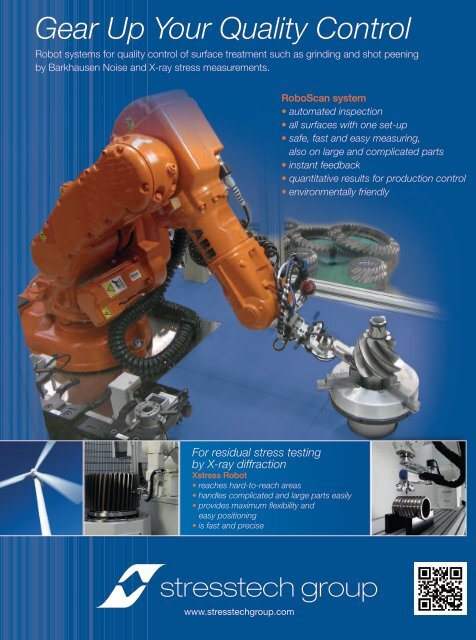
Gear Up Your Quality Control Robot systems for quality control of surface treatment such as grinding and shot peening by Barkhausen Noise and X-ray stress measurements. RoboScan system • automated inspection • all surfaces with one set-up • safe, fast and easy measuring, also on large and complicated parts • instant feedback • quantitative results for production control • environmentally friendly For residual stress testing by X-ray diffraction Xstress Robot • reaches hard-to-reach areas • handles complicated and large parts easily • provides maximum flexibility and easy positioning • is fast and precise www.stresstechgroup.com
- Page 1 and 2: August 2012 ® www.geartechnology.c
- Page 3 and 4: Plan to see us at IMTS! http://info
- Page 5 and 6: Customers Say it Best We are extrem
- Page 7 and 8: Think Big! Grind Big! IMTS CHICAGO
- Page 10 and 11: Our Technologies, Your Tommorow The
- Page 12 and 13: V O I C E S Adapting Lean for High-
- Page 14 and 15: V O I C E S Figure 1—Material Flo
- Page 16 and 17: P R O D U C T N E W S New Technolog
- Page 18 and 19: twiCe as big, just as fast. 2-3 wee
- Page 20 and 21: P R O D U C T Dudley’s Handbook o
- Page 22 and 23: P R O D U C T SKF Stroboscope Facil
- Page 24 and 25: IMTS North America’s Show of Show
- Page 26 and 27: iting companies want stationed on t
- Page 28 and 29: IMTS 2012 Alphabetical Listings COM
- Page 30 and 31: IMTS 2012 Product Preview Star SU B
- Page 32 and 33: MAG H 400: Run small lots or mass p
- Page 34 and 35: Kapp Technologies Booth N-7036 Two
- Page 36 and 37: different grinding wheels in one se
- Page 38 and 39: able for the machining of workpiece
- Page 40 and 41: See Drake’s newest External Threa
- Page 42 and 43: evel breakthrough See the gleason-h
- Page 44 and 45: More Than Machines, • BMS Electro
- Page 46 and 47: BRIGHT IDEAS, BRILLIANT SOLUTIONS A
- Page 50 and 51: A S K T H E E X P E R T profile shi
- Page 52 and 53: A S K T H E E X P E R T external ge
- Page 54 and 55: Powder Metal Magic Design Innovatio
- Page 56 and 57: This helical/spur combination gear
- Page 58 and 59: of tooth geometry control along wit
- Page 60 and 61: Foreground: Medical introducer part
- Page 62 and 63: High-Performance Sintered-Steel Gea
- Page 64 and 65: Figure 3—Rolling contact fatigue
- Page 66 and 67: tance, a surface-densification tech
- Page 68 and 69: Case Study Involving Surface Durabi
- Page 70 and 71: Figure 4—Baseline Gear A, Mesh 1,
- Page 72 and 73: Table 3—Roughness parameters of b
- Page 74 and 75: Figure 17—ISF Gear A, Mesh 1: pos
- Page 76 and 77: Table 9—Design requirements for I
- Page 78 and 79: N E W S In Memoriam James J. Cervin
- Page 80 and 81: N E W S In her new role, Codina is
- Page 82 and 83: N E W S Sunnen Receives Global Pion
- Page 84 and 85: MFN is Official Cooperation Partner
- Page 86 and 87: C A L E N D A R September 10-15—I
- Page 88 and 89: A D V E R T I S E R S i n d e x ADV
- Page 90 and 91: A D D E N D U M Technology Mash-Up
- Page 92: HÖFLER by KLINGELNBERG: Gear Hobbi
<strong>Gear</strong> Up Your Quality Control<br />
Robot systems for quality control of surface treatment such as gr<strong>in</strong>d<strong>in</strong>g and shot peen<strong>in</strong>g<br />
by Barkhausen Noise and X-ray stress measurements.<br />
RoboScan system<br />
• automated <strong>in</strong>spection<br />
• all surfaces with one set-up<br />
• safe, fast and easy measur<strong>in</strong>g,<br />
also on large and complicated parts<br />
• <strong>in</strong>stant feedback<br />
• quantitative results for production control<br />
• environmentally friendly<br />
For residual stress test<strong>in</strong>g<br />
by X-ray diffraction<br />
Xstress Robot<br />
• reaches hard-to-reach areas<br />
• handles complicated and large parts easily<br />
• provides maximum flexibility and<br />
easy position<strong>in</strong>g<br />
• is fast and precise<br />
www.stresstechgroup.com


