Technical Product Information - Breitband-Lambda
Technical Product Information - Breitband-Lambda
Technical Product Information - Breitband-Lambda
You also want an ePaper? Increase the reach of your titles
YUMPU automatically turns print PDFs into web optimized ePapers that Google loves.
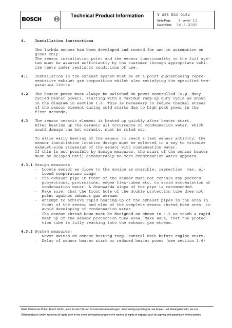
4. Installation instructions<br />
<strong>Technical</strong> <strong>Product</strong> <strong>Information</strong><br />
Y 258 E00 015e<br />
Seite/Page 9 von/of 13<br />
Datum/Date 14.6.2005<br />
The lambda sensor has been developed and tested for use in automotive engines<br />
only.<br />
The sensor installation point and the sensor functionality in the full system<br />
must be assured sufficiently by the customer through appropriate vehicle<br />
tests under realistic conditions of use.<br />
4.1 Installation in the exhaust system must be at a point guaranteeing representative<br />
exhaust gas composition whilst also satisfying the specified temperature<br />
limits.<br />
4.2 The heater power must always be switched on power controlled (e.g. duty<br />
cycled heater power), starting with a maximum ramp-up duty cycle as shown<br />
in the diagram in section 1.6. This is necessary to reduce thermal stress<br />
of the sensor element during cold starts due to high peak power in the<br />
first seconds.<br />
4.3 The sensor ceramic element is heated up quickly after heater start.<br />
After heating up the ceramic all occurrence of condensation water, which<br />
could damage the hot ceramic, must be ruled out.<br />
To allow early heating of the sensor to reach a fast sensor activity, the<br />
sensor installation location design must be selected in a way to minimize<br />
exhaust-side stressing of the sensor with condensation water.<br />
If this is not possible by design measures, the start of the sensor heater<br />
must be delayed until demonstrably no more condensation water appears.<br />
4.3.1 Design measures:<br />
- Locate sensor as close to the engine as possible, respecting max. allowed<br />
temperature range<br />
- The exhaust pipe in front of the sensor must not contain any pockets,<br />
projections, protrusions, edges flex-tubes etc. to avoid accumulation of<br />
condensation water. A downwards slope of the pipe is recommended.<br />
- Make sure, that the front hole of the double protection tube does not<br />
point against exhaust gas stream.<br />
- Attempt to achieve rapid heating-up of the exhaust pipes in the area in<br />
front of the sensor and also of the complete sensor thread boss area, to<br />
avoid developing of condensation water<br />
- The sensor thread boss must be designed as shown in 4.9 to reach a rapid<br />
heat up of the sensor protection tube area. Make sure, that the protection<br />
tube is fully reaching into the exhaust gas stream.<br />
4.3.2 System measures:<br />
- Never switch on sensor heating resp. control unit before engine start.<br />
- Delay of sensor heater start or reduced heater power (see section 1.6)<br />
©Alle Rechte bei Robert Bosch GmbH, auch für den Fall von Schutzrechtsanmeldungen. Jede Verfügungsbefugnis, wie Kopier- und Weitergaberecht, bei uns.<br />
©Robert Bosch GmbH reserves all rights even in the event of industrial property.We reserve all rights of disposal such as copying and passing on to third parties


