Chapter 1 - Pacific Communications
Chapter 1 - Pacific Communications
Chapter 1 - Pacific Communications

You also want an ePaper? Increase the reach of your titles
YUMPU automatically turns print PDFs into web optimized ePapers that Google loves.
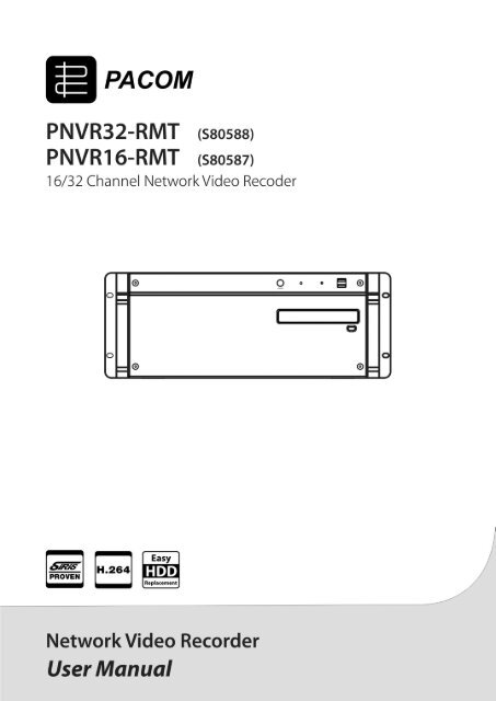
Network Video Recorder<br />
WARNING<br />
RISK OF ELECTRIC SHOCK<br />
DO NOT OPEN<br />
WARNING: TO REDUCE THE RISK OF ELECTRIC SHOCK,<br />
DO NOT REMOVE COVER (OR BACK).<br />
NO USER-SERVICEABLE PARTS INSIDE.<br />
REFER SERVICING TO QUALIFIED<br />
SERVICE PERSONNEL.<br />
The lightning flash with arrowhead symbol, within an equilateral triangle, is intended to alert<br />
the user to the presence of uninsulated "dangerous voltage" within the product's enclosure<br />
that may be of sufficient magnitude to constitute a risk of electric shock.<br />
The exclamation point within an equilateral triangle is intended to alert the user to the<br />
presence of important operating and maintenance (servicing) instructions in the literature<br />
accompanying the appliance.<br />
COMPLIANCE NOTICE OF FCC:<br />
THIS EQUIPMENT HAS BEEN TESTED AND FOUND TO COMPLY WITH THE LIMITS FOR A CLASS A DIGITAL<br />
DEVICE, PURSUANT TO PART 15 OF THE FCC RULES. THESE LIMITS ARE DESIGNED TO PROVIDE<br />
REASONABLE PROTECTION AGAINST HARMFUL INTERFERENCE WHEN THE EQUIPMENT IS OPERATED IN<br />
A COMMERCIAL ENVIRONMENT. THIS EQUIPMENT GENERATES, USES, AND CAN RADIATE RADIO<br />
FREQUENCY ENERGY AND IF NOT INSTALLED AND USED IN ACCORDANCE WITH THE INSTRUCTION<br />
MANUAL, MAY CAUSE HARMFUL INTERFERENCE TO RADIO COMMUNICATIONS. OPERATION OF THIS<br />
EQUIPMENT IN A RESIDENTIAL AREA IS LIKELY TO CAUSE HARMFUL INTERFERENCE, IN WHICH CASE<br />
USERS WILL BE REQUIRED TO CORRECT THE INTERFERENCE AT THEIR OWN EXPENSE.<br />
WARNING: CHANGES OR MODIFICATIONS NOT EXPRESSLY APPROVED BY THE PARTY RESPONSIBLE<br />
FOR COMPLIANCE COULD VOID THE USER’S AUTHORITY TO OPERATE THE EQUIPMENT.<br />
THIS CLASS OF DIGITAL APPARATUS MEETS ALL REQUIREMENTS OF THE CANADIAN INTERFERENCE-<br />
CAUSING EQUIPMENT REGULATIONS.<br />
The information in this manual is believed to be accurate as of the date of publication. We are not responsible for any<br />
problems resulting from the use thereof. The information contained herein is subject to change without notice. Revisions<br />
or new editions to this publication may be issued to incorporate such changes.<br />
The software included in this product contains some Open Sources. You may obtain the complete corresponding<br />
source code from us. See the Open Source Guide on the software CD (OpenSourceGuide\OpenSourceGuide.pdf)<br />
or as a printed document included along with the User's Manual.<br />
i
User’s Manual<br />
Important Safeguards<br />
1. Read Instructions<br />
All the safety and operating instructions should be read before the<br />
appliance is operated.<br />
2. Keep Instructions<br />
The safety and operating instructions should be kept for future<br />
reference.<br />
3. Cleaning<br />
Unplug this equipment from the wall outlet before cleaning it. Do<br />
not use liquid aerosol cleaners. Use a damp soft cloth for cleaning.<br />
4. Attachments<br />
Never add any attachments and/or equipment without the approval<br />
of the manufacturer as such additions may result in the risk of fire,<br />
electric shock or other personal injury.<br />
5. Water and/or Moisture<br />
Do not use this equipment near water or in contact with water.<br />
6. Accessories<br />
Do not place this equipment on an unstable cart, stand or table. The<br />
equipment may fall, causing serious injury to a child or adult, and<br />
serious damage to the equipment. Wall or shelf mounting should<br />
follow the manufacturer's instructions, and should use a mounting<br />
kit approved by the manufacturer.<br />
This equipment and cart combination should be moved with care.<br />
Quick stops, excessive force, and uneven surfaces may cause the<br />
equipment and cart combination to overturn.<br />
7. Ventilation<br />
Slots and openings in the cabinet and the back or bottom are provided<br />
for ventilation, and to ensure reliable operation of the equipment and<br />
to protect it from overheating. These openings must not be blocked<br />
or covered. Do not block these openings or allow them to be blocked<br />
by placing the equipment on a bed, sofa, rug, or bookcase. Ensure that<br />
there is adequate ventilation and that the manufacturer’s instructions<br />
have been adhered to.<br />
8. Power Sources<br />
This equipment should be operated only from the type of power source<br />
indicated on the marking label. If you are not sure of the type of<br />
power, please consult your equipment dealer or local power company.<br />
9. Power Cords<br />
Operator or installer must remove power and other connections before<br />
handling the equipment.<br />
10. Lightning<br />
For added protection for this equipment during a lightning storm,<br />
or when it is left unattended and unused for long periods of time,<br />
unplug it from the wall outlet and disconnect the antenna or cable<br />
system. This will prevent damage to the equipment due to lightning<br />
and power-line surges.<br />
11. Overloading<br />
Do not overload wall outlets and extension cords as this can result<br />
in the risk of fire or electric shock.<br />
12. Objects and Liquids<br />
Never push objects of any kind through openings of this equipment<br />
as they may touch dangerous voltage points or short out parts that<br />
could result in a fire or electric shock. Never spill liquid of any kind<br />
on the equipment.<br />
13. Servicing<br />
Do not attempt to service this equipment yourself. Refer all servicing<br />
to qualified service personnel.<br />
14. Damage requiring Service<br />
Unplug this equipment from the wall outlet and refer servicing to<br />
qualified service personnel under the following conditions:<br />
A. When the power-supply cord or the plug has been damaged.<br />
B. If liquid is spilled, or objects have fallen into the equipment.<br />
C. If the equipment has been exposed to rain or water.<br />
D. If the equipment does not operate normally by following the<br />
operating instructions, adjust only those controls that are covered<br />
by the operating instructions as an improper adjustment of other<br />
controls may result in damage and will often require extensive work<br />
by a qualified technician to restore the equipment to its normal<br />
operation.<br />
E. If the equipment has been dropped, or the cabinet damaged.<br />
F. When the equipment exhibits a distinct change in performance —<br />
this indicates a need for service.<br />
15. Replacement Parts<br />
When replacement parts are required, be sure the service technician<br />
has used replacement parts specified by the manufacturer or that have<br />
the same characteristics as the original part. Unauthorized substitutions<br />
may result in fire, electric shock or other hazards.<br />
16. Safety Check<br />
Upon completion of any service or repairs to this equipment, ask<br />
the service technician to perform safety checks to determine that the<br />
equipment is in proper operating condition.<br />
17. Field Installation<br />
This installation should be made by a qualified service person and<br />
should conform to all local codes.<br />
18. Telnet Communication Cable<br />
Caution: To reduce the risk of fire, use only No. 26 AWG or larger<br />
telecommunication line cord.<br />
19. Danger of explosion if battery is incorrectly replaced. Replace<br />
only with same or equivalent type recommended by manufacturer.<br />
Discard used batteries according to the manufacturer’s instruction.<br />
WEEE (Waste Electrical & Electronic Equipment)<br />
Correct Disposal of This Product<br />
(Applicable in the European Union and other European countries with separate collection systems)<br />
This marking shown on the product or its literature, indicates that it should not be disposed with other household wastes at the<br />
end of its working life. To prevent possible harm to the environment or human health from uncontrolled waste disposal, please<br />
separate this from other types of wastes and recycle it responsibly to promote the sustainable reuse of material resources.<br />
Household users should contact either the retailer where they purchased this product, or their local government office, for<br />
details of where and how they can take this item for environmentally safe recycling.<br />
Business users should contact their supplier and check the terms and conditions of the purchase contract. This product should<br />
not be mixed with other commercial wastes for disposal.<br />
ii
Network Video Recorder<br />
Table of Contents<br />
<strong>Chapter</strong> 1 — Introduction ............................................................................................ 1<br />
1.1 Features ............................................................................................................ 1<br />
1.2 System Diagram ................................................................................................ 2<br />
1.3 Rear Panel ........................................................................................................ 2<br />
1.4 Front Panel ........................................................................................................ 3<br />
1.5 Upgrade ............................................................................................................. 3<br />
Remote Upgrade ............................................................................................... 4<br />
1.6 Tuning On/Off the System ................................................................................. 7<br />
<strong>Chapter</strong> 2 — Getting Started ....................................................................................... 9<br />
2.1 Connecting ........................................................................................................ 9<br />
2.2 System Setting ................................................................................................ 10<br />
2.3 Registering Devices ........................................................................................ 13<br />
2.4 Live Video Monitoring ...................................................................................... 17<br />
2.5 Recording ........................................................................................................ 17<br />
2.6 Playing Recorded Video .................................................................................. 18<br />
<strong>Chapter</strong> 3 — System Overview ................................................................................. 19<br />
3.1 Service Manager ............................................................................................. 19<br />
Menu ............................................................................................................... 19<br />
Status Display ................................................................................................. 20<br />
Service Database Backup/Restore ................................................................. 21<br />
Cascade .......................................................................................................... 22<br />
3.2 Setup ............................................................................................................... 24<br />
Service ............................................................................................................ 24<br />
Device ............................................................................................................. 25<br />
User ................................................................................................................. 27<br />
Recording Schedule ........................................................................................ 27<br />
Event Management ......................................................................................... 28<br />
3.3 Client ............................................................................................................... 29<br />
Menu ............................................................................................................... 31<br />
Site List ........................................................................................................... 32<br />
Panel ............................................................................................................... 33<br />
Menu – Preference Settings ........................................................................... 34<br />
<strong>Chapter</strong> 4 — Live Video Monitoring .......................................................................... 41<br />
4.1 Monitoring Video ............................................................................................. 41<br />
Layout Monitoring ........................................................................................... 43<br />
Layout Sequence Monitoring .......................................................................... 44<br />
Camera Sequence Monitoring ........................................................................ 47<br />
4.2 Map Monitoring ............................................................................................... 48<br />
4.3 Controlling Cameras ....................................................................................... 50<br />
PTZ Control ..................................................................................................... 51<br />
Zoom Control .................................................................................................. 52<br />
Image Effect .................................................................................................... 53<br />
Text-In Viewer ................................................................................................. 53<br />
iii
User’s Manual<br />
4.4 Controlling Maps ............................................................................................. 53<br />
<strong>Chapter</strong> 5 — Recording ............................................................................................. 57<br />
5.1 Setting up Recording Schedule ...................................................................... 57<br />
Setting up Time-Lapse Recording .................................................................. 59<br />
Setting up Event-Based Recording ................................................................. 61<br />
Managing Schedule ........................................................................................ 65<br />
Setting up Instant Recording ........................................................................... 66<br />
<strong>Chapter</strong> 6 — Recorded Video Playback & Exportation ............................................. 69<br />
6.1 Playing back Recorded Video ......................................................................... 69<br />
Snapshot on Motion Event .............................................................................. 73<br />
Object/Motion Search ..................................................................................... 73<br />
Zoom Control .................................................................................................. 74<br />
Image Effect .................................................................................................... 75<br />
6.2 Exporting Recorded Video .............................................................................. 75<br />
Exporting as a Self-Player File ........................................................................ 75<br />
Exporting as an AVI File ................................................................................. 78<br />
<strong>Chapter</strong> 7 — Event Handling ..................................................................................... 81<br />
7.1 Handling a Monitoring Event ........................................................................... 81<br />
Monitoring Video ............................................................................................. 81<br />
Playing Video .................................................................................................. 82<br />
7.2 Handling Event Recorded Video ..................................................................... 83<br />
<strong>Chapter</strong> 8 — Device Status Monitoring ..................................................................... 85<br />
8.1 Health Monitoring ............................................................................................ 85<br />
8.2 Device Check .................................................................................................. 86<br />
8.3 Status Monitoring ............................................................................................ 87<br />
<strong>Chapter</strong> 9 — Log Search ........................................................................................... 89<br />
<strong>Chapter</strong> 10 — Streaming ........................................................................................... 91<br />
<strong>Chapter</strong> 11 — Device Management .......................................................................... 93<br />
11.1 Registering Devices ...................................................................................... 94<br />
11.2 Managing Devices ......................................................................................... 98<br />
Editing Device Information .............................................................................. 99<br />
Changing Device’s Setting Remotely ........................................................... 102<br />
Upgrading Device’s Software ........................................................................ 103<br />
Checking Device Status ................................................................................ 103<br />
Editing Input/Output Device Information ....................................................... 104<br />
11.3 Remote Setup of ONVIF TM Conformance Protocol Devices ....................... 104<br />
<strong>Chapter</strong> 12 — User Management ........................................................................... 111<br />
<strong>Chapter</strong> 13 — Storage Management ...................................................................... 113<br />
<strong>Chapter</strong> 14 — Event Management .......................................................................... 115<br />
iv
Network Video Recorder<br />
14.1 Setting up Event Management Schedule .................................................... 115<br />
Managing Schedule ...................................................................................... 122<br />
14.2 Managing Events ........................................................................................ 123<br />
Live Popup .................................................................................................... 123<br />
Event Acknowledgement .............................................................................. 124<br />
<strong>Chapter</strong> 15 — Map Editor ........................................................................................ 127<br />
15.1 Registering Map .......................................................................................... 127<br />
15.2 Setting up Map ............................................................................................ 128<br />
<strong>Chapter</strong> 16 — Controlling With a Network Keyboard .............................................. 131<br />
16.1 Registering .................................................................................................. 131<br />
16.2 Connecting .................................................................................................. 132<br />
16.3 Operating..................................................................................................... 132<br />
16.4 Network Keyboard Buttons ......................................................................... 134<br />
<strong>Chapter</strong> 17 — Remote Monitoring ........................................................................... 137<br />
17.1 Installation ................................................................................................... 137<br />
17.2 Uninstall ....................................................................................................... 139<br />
Appendix .................................................................................................................. 141<br />
Schedule Setup Examples of Event Recording Mode ........................................ 141<br />
OSD Information.................................................................................................. 143<br />
Network Disconnection Log ................................................................................ 143<br />
Troubleshooting................................................................................................... 144<br />
Specification ............................................................................................................ 147<br />
Index ........................................................................................................................ 149<br />
v
User’s Manual<br />
vi
Network Video Recorder<br />
<strong>Chapter</strong> 1 — Introduction<br />
1.1 Features<br />
This network video recorder (NVR) provides monitoring of video from network video transmitters, network<br />
cameras and DVRs, recording of monitoring video (DVR excluded) and playback of video recorded in the<br />
NVR system or DVR.<br />
• Remote monitoring of live images<br />
• Remote monitoring of live images in multiple Client systems through a streaming service (the number<br />
of channels that can be streamed equals the number of channels that can be recorded)<br />
• Up to 20 simultaneous connections to the NVR system<br />
• Software upgrades and multiple systems setup remotely (supported only for devices which provide the<br />
functions)<br />
• Display of system log information (supported only for devices which use the SiRiS protocol)<br />
• Map monitoring of live images<br />
• Centralized system operation and management and event handling<br />
• Enhanced security using the SSL function<br />
• Two-way audio communication and audio broadcasting<br />
• Enhanced security by setting up different authorities for each user group<br />
• Controlling with a network keyboard<br />
• Text-in and alarm function via TCP networking<br />
• Intuitive GUI<br />
• The following are supported only for network cameras and network video transmitters:<br />
− Recording of video and playback of the recorded video<br />
− Instant Recording of monitored images<br />
− Audio recording<br />
− Stable recording using proprietary video database file system<br />
• The following are supported only for DVRs:<br />
− Playback of video recorded in DVRs<br />
− Remote control of panic recording<br />
• Number of devices that can be registered and channels that can be recorded and streamed:<br />
− Registration: Maximum of 1,024 devices including devices which do not use the SiRiS protocol (The<br />
devices which do not use the SiRiS protocol can be registered up to the maximum number of available<br />
recording channels. For example, if the NVR system is a 16-channel model, up to 16 devices that do<br />
not use the SiRiS protocol can be registered.)<br />
− Recording (not supported for DVRs): Maximum of 16 (16-channel model) /32 (32-channel model) channels<br />
− Streaming (not supported for DVRs): The number of channels that can be streamed equals the number<br />
of channels that can be recorded.<br />
NOTES:<br />
• In this document, the “remote system” refers to a network video transmitter or DVR which cameras are<br />
connected to or a network camera. The “client system” refers to a PC running the Client program to<br />
connect to the NVR system remotely.<br />
• If the device is a four-channel network video transmitter which uses the SiRiS protocol, all four cameras<br />
are counted even if some of the four cameras are disabled, and four channels per network video transmitter<br />
are deducted from the number of channels available for recording and streaming.<br />
• This document covers the 16- and 32-channel network video recorders. For simplicity, the illustrations<br />
and descriptions in this document refer to the 32-channel model. Refer to Appendix (p. 141) for the<br />
system specifications of each model.<br />
1
User’s Manual<br />
NOTES:<br />
• This product includes software developed by the OpenSSL Project for use in the OpenSSL Toolkit<br />
(http://www.openssl.org/).<br />
• The software included in this product contains some Open Sources. You may obtain the complete<br />
corresponding source code from us. See the Open Source Guide on the software CD (OpenSourceGuide\<br />
OpenSourceGuide.pdf) or as a printed document included along with this document.<br />
1.2 System Diagram<br />
1.3 Rear Panel<br />
1 Power In: Connect a power cord.<br />
2 USB Port: Connect USB devices.<br />
3 Network (RJ-45): Connect a Cat5 cable with an RJ-45 jack. Refer to 2.2 System Setting (p. 10) for<br />
details about network setting.<br />
4 Audio In (mic): Connect a microphone. This is for two-way audio communication.<br />
5 Audio Out (Line out): Connect a speaker.<br />
6 Audio In (Line in): Connect a line-in device. This is for two-way audio communication.<br />
2
Network Video Recorder<br />
7 DVI: Connect a PC monitor. Connect a monitor before turning on the system. Video might not be<br />
displayed on the monitor when connecting a monitor after turning on the system. Refer to 3.3 Client,<br />
Menu – Preference Settings, Screen Format (p. 35) for details about the monitor setting.<br />
8 D-Sub: Connect a PC monitor. Connect a monitor before turning on the system. Video might not be<br />
displayed on the monitor when connecting a monitor after turning on the system. Refer to 3.3 Client,<br />
Menu – Preference Settings, Screen Format (p. 35) for details about the monitor setting.<br />
NOTE: The location of DVI and D-Sub connectors is subject to change without notice.<br />
1.4 Front Panel<br />
1 Power Button: Turns on or off the system.<br />
2 Power LED: Is lit when the unit is turned on.<br />
3 HDD LED: Flickers when the unit accesses to the hard disk drive.<br />
4 DVD RW: Used to save the recorded data on the CD-RW or DVD RW media.<br />
5 USB Port: Connects the USB devices.<br />
NOTE: Windows may not operate properly when using the USB connectors on the front panel of the unit,<br />
depending on the model type of the USB device. In this case, connect the USB device after Windows boots<br />
properly or use the USB connectors located on the rear panel.<br />
1.5 Upgrade<br />
You can upgrade the NVR system by using a USB flash drive as follows:<br />
NOTE: Upgrading by using a USB flash drive is supported for the users belonging to the default user group<br />
(Administrators).<br />
1. Connect a USB flash drive containing the upgrade package file to the NVR while the SiRiS Client program<br />
is running.<br />
2. Click SiRiS Update under the System Menu in the NVR system. The following window appears.<br />
3
User’s Manual<br />
Click the button and select a Standard.conf file. The folder path and software version of the selected<br />
file is displayed. → Click the Upgrade button. → The SiRiS Client program closes and the NVR system<br />
enters Windows mode. → The NVR system starts upgrading. When upgrade is complete, the SiRiS<br />
program runs automatically.<br />
Remote Upgrade<br />
You can upgrade the NVR system remotely by using the installation file of the software version to upgrade<br />
if an update service is running.<br />
Update Service Setup<br />
1. Run the Service Manager program in the NVR<br />
system. Refer to 3.1 Service Manager (p. 19)<br />
for details about running the Service Manager<br />
program. Select the Administration Service in<br />
the service list.<br />
2. Click Option menu and select Update Package and then<br />
select Update Service tab. Check the Use box and enter<br />
the IP address and port number of the update server.<br />
Update Service Installation<br />
System Requirements<br />
• Operating System: Microsoft ® Windows ® XP 32-bit/Vista (Home Standard, Business, Ultimate, Enterprise),<br />
Microsoft ® Windows ® 7 (Home Premium, Professional, Ultimate), Microsoft ® Windows ® 8 (Pro, Enterprise),<br />
Microsoft ® Windows ® Server 2003/2008<br />
• CPU: Intel Core II Quad 8200 2.33 GHz/Intel Xeon 3.0 GHz or faster<br />
• RAM: 2GB or more<br />
• VGA: ATI Radeon TM HD 2400 or NVIDIA GeForce FX5500 (ATI recommended) (1024x768, 24bpp<br />
or higher)<br />
• Hard Disk Drive: 5 GB or more free space for each service (for example, 10 GB or more free space when<br />
installing administration and monitoring services)<br />
• LAN: Gigabit Ethernet or faster<br />
4
Network Video Recorder<br />
NOTES:<br />
• The SiRiS program operates under 32 bit operating system. When you install it under 64 bit of Microsoft ®<br />
Windows ® Vista or later operating system, it is installed and operates in 32 bit compatibility mode.<br />
• Disable your PC’s Windows power saving function: Start menu → Power Options → set both Turn off the<br />
display and Put the computer to sleep to Never (Power Options → Power Schemes tab → set both Turn<br />
off monitor and Turn off hard disks to Never when using the Microsoft ® Windows ® XP operating system).<br />
1. Insert the software CD in the update server.<br />
2. Run the PNVRUpdateServiceSetup.exe file in the Setup folder of the software CD.<br />
NOTE: The User Account Control window might appear when using the Microsoft ® Windows ® Vista or later<br />
operating system. Click Allow and install the software following the instructions.<br />
3. Select the language in which to run the program and then click OK.<br />
NOTES:<br />
• To properly display the selected language, your PC’s operating system should be set to support the<br />
selected language.<br />
• To change the SiRiS program’s language after the software has been installed, select Language Selector<br />
in the SiRiS → Utility folder of the Start menu before running the SiRiS Setup program.<br />
4. When the following screen appears, click Next.<br />
5. Designate the folder path to install the service. Clicking the<br />
Disk Cost… button shows the available and required disk<br />
space for each hard disk drive for the installation. Then click<br />
Next.<br />
5
User’s Manual<br />
6. When the following screens appear, click Next.<br />
NOTE: .NET Framework and the Visual C++ Runtime Libraries are installed automatically, and it may take<br />
some time. This installation step will be skipped if the programs are already installed on your computer.<br />
7. When the following screen appears, click the Close button<br />
to complete the installation.<br />
Upgrade<br />
1. Go to the Start Menu in the update server → Click SiRiS → Run the Update Manager program.<br />
6
Network Video Recorder<br />
• Option: Designates the upgrade file or sets up the port number of the update server.<br />
− Update Package: Designates the folder path of the upgrade installation file.<br />
− Port Setup: Sets the port number of the update server.<br />
• Log: Selecting Show Log allows you to check and search the system log.<br />
Setting up the time range of the log and clicking<br />
the Search button displays the log information.<br />
Selecting First displays from the oldest log<br />
entries regardless of date. Selecting Last displays<br />
to the newest log entries regardless of date.<br />
2. Click the Option menu and select Update Package.<br />
Click the button and designate the folder<br />
path of the upgrade installation file. Click the<br />
OK button.<br />
3. Click the Update button at the bottom of the Update Manager screen. For a Client system with no<br />
SiRiS service program installed, clicking the Update button upgrades the Client program. For the NVR<br />
system connects to the update service periodically and automatically upgrades if necessary.<br />
1.6 Tuning On/Off the System<br />
Pressing the power button on the front panel turn on the system and the SiRiS program runs. Clicking<br />
Shutdown under the System menu in the SiRiS Client program or pressing the power button on the front<br />
panel while the system turns on will ask you to confirm turning off the system and the system turns off when<br />
you confirm.<br />
NOTE: Connect a monitor before turning on the system. Video might not be displayed on the monitor when<br />
connecting a monitor after turning on the system.<br />
7
User’s Manual<br />
8
Network Video Recorder<br />
<strong>Chapter</strong> 2 — Getting Started<br />
2.1 Connecting<br />
The SiRiS program runs automatically when the NVR system turns on. You are required to log in to the<br />
NVR system as follows.<br />
Login<br />
Go to the System Menu at the top left corner of the screen and click Login.<br />
• Site Name: Select Local Host to connect to the current NVR system. If you want to connect to another<br />
NVR system, add the NVR system to the list or modify information about the NVR system in the list<br />
by clicking the button at the right.<br />
− Site Name, Service Address, Service Port: Designate the name<br />
of the NVR system and enter the IP address and port number of the<br />
NVR system (default: 11001). If the NVR system uses the DVRNS<br />
function, check Use DVRNS and enter the IP address (domain<br />
name) and port number of the DVRNS server that the NVR system<br />
is registered. It allows you to enter the name instead of the IP address<br />
of the NVR system when entering Service Address. The name you<br />
enter should be the same as the name registered on the DVRNS<br />
server. Refer to 2.2 System Setting, DVRNS (p. 12) for details<br />
about the DVRNS function.<br />
• User ID, Password: Enter your user ID and password. The default user ID is admin and default password<br />
is 12345678. You can change the user ID and password in the User menu. Refer to <strong>Chapter</strong> 12 —<br />
User Management (p. 111) for details.<br />
• Remember my ID on this computer: Check the box if you want to save your ID for logging on.<br />
• Restore last Live sessions: Check the box if you want to restore the previous live monitoring sessions<br />
in the current Live panels of the Client program.<br />
Running SiRiS Program<br />
You can run the SiRiS program as follows. Refer to <strong>Chapter</strong> 3 — System Overview (p. 19) for details<br />
about each program.<br />
• Client Program: It runs automatically when the NVR system turns on.<br />
• Setup Program: Log in to the NVR system and click SiRiS Setup from the System menu at the top left<br />
corner of the screen.<br />
9
User’s Manual<br />
• Service Manager Program: Log in to the NVR system and click SiRiS Service Manager from the System<br />
menu at the top left corner of the screen.<br />
2.2 System Setting<br />
Run the Setup program and set up the NVR system.<br />
Click the<br />
(System Setup) button to display the system setup screen.<br />
10
Network Video Recorder<br />
Date/Time<br />
• Date, Time, Time Zone: Displays the date, time<br />
and time zone of the NVR system.<br />
• NTP Sync<br />
− Automatic Sync: Automatically synchronizes<br />
the time with a time server. Enter the IP address or<br />
the domain name of the time server and set the time<br />
interval for synchronization.<br />
− Run as Server: Check the box to run the NVR<br />
system as a time server.<br />
Network<br />
A list of network cards installed in the NVR system is<br />
displayed. Selecting a network card displays the<br />
network information of the selected network card and<br />
clicking the Setup button allows you to change the<br />
network settings. Ask your network provider for details<br />
about the network connection type and connection<br />
information for the NVR system or the IP address of the<br />
DNS server.<br />
• Type: Select the type of NVR system’s network<br />
configuration.<br />
− Set Manually: Select when the system is using a<br />
static IP address for network connection, and set up<br />
LAN parameters manually.<br />
− DHCP: Select when the system is networked via DHCP (Dynamic Host Configuration Protocol). Click<br />
the Apply button, and network information is automatically assigned to the device. If the NVR system<br />
is configured for a DHCP network, it is best to use the DVRNS function because the NVR system’s<br />
IP address might change frequently. See DVRNS below for details about the DVRNS function.<br />
• DNS Server: Enter the IP address of the DNS server. If you set up the DNS server, the domain name<br />
of the server can be used instead of the IP address during the DVRNS or time server setup. Ask your<br />
Internet service provider for the IP Address of the DNS Server. When the NVR system is networked<br />
via DHCP, selecting From DHCP automatically assigns the IP address of the DNS server. The assigned<br />
IP address is displayed the next time it is connected.<br />
NOTE: If the NVR system uses a NAT (Network Address Translation) device for network connection, it may<br />
be necessary that you set up port forwarding of all service ports on the NAT device. You can check the<br />
service ports in the Service Manager program (Option menu → Service Option).<br />
• Administration service port (default: 11001): You need to do port forwarding for the administration service<br />
port for any of actions behind a NAT device.<br />
• Streaming service port (default: 11003):<br />
− When all devices are registered in the streaming service, you do not need to do port forwarding for the<br />
devices.<br />
− When there are devices that are not registered in the streaming service, you need to do port forwarding<br />
for watch ports of each device.<br />
11
User’s Manual<br />
• Recording service port (default: 11002): You need to do port forwarding for the recording service port to<br />
see recorded data in the NVR system.<br />
• Monitoring service port (default: 11004): You need to do port forwarding for the monitoring service port<br />
to receive event information from DVRs and IP products.<br />
DVRNS<br />
• Server Address, Server Port: Enter the IP address<br />
(domain name) and port number of the DVRNS server<br />
to register the NVR system.<br />
• Use DVRNS: Allows you to enter the name<br />
instead of the IP address of the NVR system by using<br />
the DVRNS function when connecting to the NVR<br />
system.<br />
− Use NAT: Check the box when the NVR system uses a NAT (Network Address Translation) device<br />
for network connection.<br />
− Name: Enter the NVR system name to be registered on the DVRNS server. Check whether or not<br />
the name is available by clicking the Check button.<br />
NOTES:<br />
• The DVRNS (DVR Name Service) function allows the NVR system to use dynamic IP addresses for remote<br />
connection. When using this function, you can access the NVR system remotely by using the NVR system<br />
name instead of its IP address. For the DVRNS function to work properly, the NVR system should be<br />
registered on the DVRNS server.<br />
• When LAN settings are changed, set up the DVRNS settings after saving your LAN changes by clicking<br />
the OK button.<br />
• You will need to get the IP address or domain name of the DVRNS server from your network administrator.<br />
You can use the domain name instead of IP address if you set up the DNS server during the IP Address<br />
setup.<br />
• When using a NAT (Network Address Translation) device, refer to the NAT manufacturer’s instructions<br />
for the proper network settings.<br />
• The NVR system name you entered in the Name field should be checked by clicking the Check button,<br />
otherwise the DVRNS changes will not be saved. When entering no name or a name already registered<br />
on the DVRNS server, an error message displays.<br />
SSL<br />
• Use SSL: Allows you to enhance the security of data<br />
transferred between services of the SiRiS program<br />
by using the SSL (Secure Sockets Layer) protocol.<br />
Using the SSL function might cause congestion in the<br />
NVR system depending on the security level. Log in<br />
the SiRiS program again after you change the setting.<br />
When the setting is changed, all services that are<br />
currently connected to the administration service<br />
reconnect, and the SiRiS Setup and SiRiS Client<br />
programs are logged out.<br />
12
Network Video Recorder<br />
Email<br />
Enter the SMTP server information. The NVR system<br />
can send an email to preset Client users when an event<br />
is detected or to specific recipients when any services<br />
are disconnected from the administration service.<br />
• SMTP Server, Port: Enter the email address and port<br />
number of the SMTP server. Select Use SSL/TLS if<br />
the SMTP server requires SSL (Secure Sockets Layer)<br />
authentication.<br />
• Use Authentication: Select and enter the ID and<br />
password if the SMTP server requires user<br />
authentication.<br />
• Sender: Enter the sender’s email address.<br />
• Email Test: Click the button to test if the SMTP server<br />
information is correct.<br />
• Notification service connection: Sends an email<br />
to the recipients below when any services are<br />
disconnected from the administration service. Clicking<br />
the button at the bottom allows you to enter email<br />
addresses of the recipients.<br />
2.3 Registering Devices<br />
You must register devices on the administration service and add the devices to a device group in order to<br />
perform any operation.<br />
Run the SiRiS Setup program.<br />
1. Select the Device menu.<br />
2. Click All Devices in the Site panel, and then the button at the bottom of the Site List panel. The<br />
Device Scan window appears.<br />
13
User’s Manual<br />
• Protocol: Select the protocol or manufacturer of the device to scan. Event related functions may not<br />
be supported depending on the protocol that the device uses and device model (supported protocols:<br />
SiRiS protocol, some versions of the Axis/Panasonic WV (DG)/ONVIF TM Conformance protocols),<br />
and some other functions may not be supported depending on the settings of the device. Ask your<br />
dealer or distributor for details.<br />
• Scan Mode: Select the scan mode. Clicking the Start Scan button displays the results in the list. If<br />
the IP address range of the device is different from that of the NVR system, the SiRiS program considers<br />
the IP address invalid. In this case, you must change the device’s IP address to register the device.<br />
− Auto Scan (LAN): Lists devices in a LAN environment (supported only for the network video devices).<br />
If the device uses the ONVIF TM Conformance protocol, this function is supported only when you have<br />
checked the Disable WS-Discovery Windows Service (fdPHost, FDResPub) box during the<br />
software installation in Microsoft ® Windows ® Vista or later operating systems. Also, if the device<br />
uses the ONVIF TM Conformance protocol, it is recommended that the device not be networked via<br />
DHCP (Dynamic Host Configuration Protocol). If the device is networked via DHCP, connection<br />
to the device may not be made properly depending on changes in the external network environment.<br />
− IP Address: Allows you to enter the IP address of a device. You can search more than one device<br />
at a time by entering a range of IP addresses. It is recommended that the device not be networked<br />
via DHCP (Dynamic Host Configuration Protocol). If the device is networked via DHCP, connection<br />
to the device may not be made properly depending on changes in the external network environment.<br />
− DVRNS: Allows you to enter the device name registered on a DVRNS server if the device uses the<br />
DVR Name Service (DVRNS) function. Ensure the DVRNS server information on which the device<br />
is registered is correct (Service menu → (System Setup) button). If the DVRNS server information<br />
is not correct, the device will not be found.<br />
− Domain Name: Allows you to enter the device's domain name registered on a DNS server if the<br />
device uses the Domain Name Service.<br />
− Device Information File: Allows you to import an .xml file which has device connection information<br />
and lists the devices. Ask your dealer or distributor for details about the .xml file.<br />
14
Network Video Recorder<br />
• : Select the devices to register by checking the box beside each device name in the list. Selecting<br />
the Select All box selects all devices in the list.<br />
NOTES:<br />
• Camera models that are supported will require the selection of the manufacturer protocol (SiRiS protocol<br />
for EVOnet) or the ONVIF TM Conformance protocol.<br />
• All camera models listed are supported by design and changes to their firmware/protocol/versions are subject<br />
to change without notice and if communication cannot be achieved, please consult the supplier for assistance.<br />
• Please refer to the camera’s manufacturer’s manual to enable ONVIF TM Conformance protocol, as procedures<br />
may differ for each model. Alternatively ask your supplier about supported models.<br />
3. Click the Add Devices button at the bottom.<br />
• Name, Address, Device Type: Displays the name, IP address and type of the selected device. The<br />
name will be updated automatically depending on the settings of the device.<br />
• ID, Password: Enter the user ID and password which you set in the device in order to connect to that<br />
device remotely. The connection to the device is allowed only to the users under the Administrator<br />
group of the device, and recording is allowed only to the admin and pacom users under the<br />
Administrator group of the device.<br />
• Recording Service: Select a recording service (supported only for the network video devices). The<br />
device is registered on the recording service and the recording service performs recording according<br />
to a recording schedule. The channel number of the recording service indicates the maximum number<br />
of cameras that can be registered, and the name indicates the name of a recording service, which was<br />
set during the Service menu setup. When selecting the Do not record option, the SiRiS program treats<br />
the device during the Schedule setup as though it was not registered and does not perform any of the<br />
scheduled activities associated with the device. If you delete the device from the recording service<br />
after some recording has been done, you cannot search or play back the previously recorded video<br />
though you register the device again. You can check the list of devices registered on the recording<br />
service on a Device Setup tab while setting up the recording service in the Service menu. Refer to<br />
<strong>Chapter</strong> 13 — Storage Management (p. 113) for details.<br />
• Streaming Service: Select whether or not to use the streaming service for monitoring video from the<br />
device. If the device uses the streaming service, the SiRiS program transmits video from the device<br />
to the client system through the streaming service, and it allows multiple users to monitor video<br />
simultaneously. When the device uses the streaming service, icon is displayed beside the device<br />
in the Site List of the SiRiS Client program. The number of channels that can be streamed equals<br />
the number of channels that can be recorded. Refer to <strong>Chapter</strong> 10 — Streaming (p. 91) for details.<br />
15
User’s Manual<br />
• Apply to All Devices: Select to apply the same user ID and password to all selected devices if you<br />
selected more than one device and the selected devises have the same user ID and password.<br />
NOTES:<br />
• If the device is a DVR, it might be necessary to enter the DVR port numbers depending on the specifications<br />
and version of the DVR.<br />
• When registering a four-channel network video transmitter which uses the SiRiS protocol, all four<br />
cameras are automatically registered even if some of the four cameras are disabled.<br />
4. Click Device Group in the Site panel, and then the button at the bottom of the Site panel. The Add<br />
Device Group window appears.<br />
• Name: Enter the device group name.<br />
• Location: Select an upper group to which the device group will belong.<br />
• Select Devices Below, Selected Device List: Check the box beside cameras in the left panel, and<br />
the selected cameras are added to the right panel.<br />
Clicking the OK button completes the device group registration.<br />
5. Check that the device was added to the device group correctly. Click Device Group in the Site panel<br />
and then the arrow button ( ) beside Device Group. Clicking the registered group displays the list<br />
of devices added to the device group and connection status in the Site List panel. If the connection was not<br />
made properly, the network disconnection log is displayed (only for devices registered on the recording<br />
service). Refer to Appendix – Network Disconnection Log (p. 143) for details about the network<br />
disconnection log.<br />
16
Network Video Recorder<br />
Selecting the registered device group, and then the button at the bottom of the Site List panel displays<br />
the Edit Device Group window and allows you to edit the selected device group. Refer to <strong>Chapter</strong> 11<br />
— Device Management (p. 93) for details.<br />
2.4 Live Video Monitoring<br />
1. Check that the devices were added to a device group in the<br />
Site list.<br />
2. Click the Live tab on the tab panel → Select a site to connect<br />
to from the Site list, and drag and drop it on the Live screen.<br />
Live video from the selected site is displayed on the screen.<br />
Refer to <strong>Chapter</strong> 4 — Live Video Monitoring (p. 41) for<br />
details.<br />
2.5 Recording<br />
Run the Setup program. Select the Recording Schedule menu and set up the recording schedule following<br />
the procedures below. Refer to 5.1 Setting up Recording Schedule (p. 57) for details.<br />
1. Click the Schedule Setup button at the bottom. The Schedule Setup window appears, and schedule<br />
windows are displayed with the current settings for each Preset.<br />
17
User’s Manual<br />
2. Double click anywhere in the empty space of each schedule window, and the Preset setup window appears.<br />
3. Select a desired Preset from the Preset list, or click the button to add a new Preset. Selecting a Preset<br />
from the list and clicking the or button deletes the selected Preset or allows you to edit the selected<br />
Preset settings. Clicking the OK button applies the settings.<br />
2.6 Playing Recorded Video<br />
1. Check that the devices were added to a device group in the<br />
Site list.<br />
2. Click the Play or DVR Search tab on the tab panel → Select<br />
a site to connect to from the Site list and drag and drop it<br />
on the Play or DVR Search screen. Recorded video from<br />
the selected site is displayed on the screen. Refer to<br />
<strong>Chapter</strong> 6 — Recorded Video Playback & Exportation<br />
(p. 69) for details.<br />
18
Network Video Recorder<br />
<strong>Chapter</strong> 3 — System Overview<br />
The NVR system consists of the following programs:<br />
• SiRiS Service Manager: Controls the operation of services or displays system log. Refer to 3.1 Service<br />
Manager (p. 19) for details.<br />
• SiRiS Setup: Allows you to add service, devices and users, or set up recording schedules, event management<br />
schedules and storage. Refer to 3.2 Setup (p. 24) for details.<br />
• SiRiS Client: Allows you to monitor video from registered cameras, play back recorded video from<br />
storage, export recorded video and check the system log and devices’ status. Refer to 3.3 Client (p. 29)<br />
for details. You can install and run the SiRiS Client program on a PC. Refer to <strong>Chapter</strong> 17 — Remote<br />
Monitoring (p. 137) for details about installing the SiRiS Client program.<br />
3.1 Service Manager<br />
Log in to the NVR system. Refer to 2.1 Connecting, Login (p. 9) for details about the login. Go to the<br />
System Menu → Click SiRiS Service Manager → Run the SiRiS Service Manager program.<br />
1 Menu: Allows you to control the operation of the services or display the system log.<br />
2 Status Display: Displays the status of services.<br />
Menu<br />
• Option<br />
− Server Option: You can change the Watchdog setting.<br />
• Timeout (Min.): Set up the waiting time to restart<br />
services when services fail to operate. The service<br />
checks the system status. When the services fail to<br />
operate during the designated waiting time, the system<br />
restarts services automatically.<br />
• Reboot Condition: Set up the reboot condition when<br />
services fail to operate. Checking the Do Not Reboot<br />
Server option allows the system to restart services<br />
without rebooting.<br />
NOTE: “Watchdog” in the SiRiS program is a function that periodically checks the operation of the current<br />
server and restarts services automatically when services fail to operate during the predefined time.<br />
19
User’s Manual<br />
− Service Option: Selecting a service from the service list and Service Option allows you to set up<br />
the information for connection to the selected service.<br />
• Service Port: Enter the port number for connection to<br />
the selected service.<br />
• Callback Port: Enter the port number to receive a<br />
callback message from the device (supported only for the<br />
monitoring service). The port number you enter should<br />
match the port number set on the device for remote<br />
callback.<br />
• Alarm In Port: Set up the port number to receive text<br />
strings for user alarm in event detection (supported only<br />
for the monitoring service). Refer to <strong>Chapter</strong> 11 —<br />
Device Management, User Alarm In Event Setup<br />
(p. 94) for details about the user alarm in event.<br />
• RTP Incoming Port Range: Enter the port range if a<br />
device which transmits images using the RTP protocol<br />
is registered (supported only for recording or streaming<br />
services). Port range settings must be changed if the<br />
network firewall or local network allows only specific<br />
UDP/RTP port numbers. The port numbers should not<br />
conflict with the RTP port numbers of Client system or<br />
port numbers of other streaming programs. If an RTP<br />
port number conflicts with others, recording and streaming<br />
may not be available.<br />
• Log: Selecting Show Log allows you to check and search the system log.<br />
Setting up the time range of the log and clicking<br />
the Search button displays the log information.<br />
Selecting First displays from the oldest log entries<br />
regardless of date. Selecting Last displays to the<br />
newest log entries regardless of date.<br />
Status Display<br />
• Service: Displays the list of services supported by the NVR system.<br />
− Administration Service: Manages information of services, devices, users and schedules for operating<br />
the SiRiS program. When the administration service is not working, the SiRiS program does not work.<br />
− Recording Service: Records video transmitted from the network video device. When the recording<br />
service is not working, the SiRiS program does work but the system will not record and playback of<br />
previously recorded video will not be available.<br />
− Monitoring Service: Notifies live events and callback events detected at the device registered in the<br />
NVR system to the Client system.<br />
− Streaming Service: Streams images from devices to multiple client systems simultaneously.<br />
• Status: Displays the working status of each service.<br />
− Working: Indicates the service is working properly. You can operate the SiRiS Setup and SiRiS<br />
Client program, and the system performs recording based on the recording schedule.<br />
− Failed: Indicates the service failed to run because of an unknown problem. The system restarts the<br />
services or reboots the system based on the Watchdog settings. Refer to Menu (p. 19) for details about<br />
Watchdog settings.<br />
• CPU Usage: Displays the CPU usage of each service.<br />
20
Network Video Recorder<br />
• Memory Usage: Displays the memory usage of each service.<br />
Service Database Backup/Restore<br />
(Service Database Backup) button allows you to save the setting values related to services as an .iexp<br />
file in the USB storage device. (Service Database Restore) button allows you to apply the saved setting<br />
values to the current NVR system.<br />
Run the SiRiS Setup program.<br />
Service Database Backup<br />
Click the (Service Database Backup) button → Enter the name of the setup file to save the current setting<br />
values → When saving is complete, the list of Services is displayed.<br />
Service Database Restore<br />
Click the<br />
(Service Database Restore) button.<br />
21
User’s Manual<br />
Click the button at the top right corner and select a setup file to apply → Services of the current NVR<br />
system are displayed to the left of the icon. Services that are saved in the setup file are displayed to the<br />
right of the icon. Select the service to apply from the drop-down menu to the right of the icon. If<br />
there is only one service for a service type to the left of the icon or the services in the setup file are the<br />
services that were backed up from the current NVR system, the services in the setup file will be applied<br />
automatically → Click the Import button at the bottom → The SiRiS Setup program restarts after applying<br />
is complete.<br />
NOTE: This is not supported in the following cases:<br />
– When the software version of the services to the right of the icon is later than that of the services to<br />
the left of the icon.<br />
– When the type of the services to the left and right of the icon differs.<br />
Cascade<br />
If you use more than one NVR system, you can run the NVR systems as a master or slave systems. It allows<br />
you to watch video from all devices registered on the master and slave NVR systems and search all video<br />
recorded in the master and slave NVR systems in the master NVR system.<br />
Run the SiRiS Setup program → Click the<br />
(Cascade) button.<br />
22
Network Video Recorder<br />
Master NVR System<br />
• Master, Slave: Select Master. It allows you to watch or search<br />
video of this NVR system and slave NVR systems (maximum<br />
7) registered on this NVR system. The NVR system runs as a<br />
master NVR system by default and this setting will be used when<br />
the NVR system has been run as a slave NVR system and you<br />
want to change it back to a master NVR system.<br />
1. Click the OK button in the bottom.<br />
2. Enter the ID and password of the master NVR system.<br />
3. The recording and streaming services of this NVR system, which<br />
have been registered on the master NVR system, are restored to<br />
this NVR system. When the recording and streaming services<br />
are restored, devices which are not registered on the recording<br />
service are deleted and device related settings such as device<br />
groups and usage of the streaming service for monitoring video<br />
from a device, etc. are all reset and you have to check all the<br />
settings and set up again.<br />
Slave NVR System<br />
NOTE: When you change back the NVR system which has been run as a slave NVR system to a master<br />
NVR system, devices which are not registered on the recording service are deleted and device related settings<br />
such as device groups and usage of the streaming service for monitoring video from a device, etc. are all<br />
reset and you have to check all settings and set up again. If necessary, write down the current device related<br />
settings and save it in a separate place before setting the slave NVR system.<br />
• Master, Slave: Select Slave. This NVR system is registered<br />
on the master NVR system and it allows you to watch or search<br />
video of this NVR system in the master NVR system.<br />
− Master: Enter the IP address and port number of the master<br />
NVR system. If the master NVR system uses the DVRNS<br />
function, selecting Use DVRNS allows you to enter the master<br />
NVR system’s name registered on the DVRNS server instead<br />
of the IP address. You can check the name in the master NVR<br />
system’s DVRNS setting (connect to the master NVR system<br />
→ click the (System Setup) button in the Service menu of<br />
the SiRiS Setup program → click DVRNS).<br />
− Slave: If this NVR system uses the DVRNS function, no settings are required. If this NVR system<br />
does not use the DVRNS function, enter the external IP address of this NVR system. If the external<br />
IP address is not correct, you may not watch or search video. If you want, you can change the DVRNS<br />
settings of this NVR system (click the (System Setup) button in the Service menu → click DVRNS).<br />
1. Click the OK button in the bottom.<br />
2. Enter the ID and password of the master NVR system.<br />
3. The recording and streaming services of this NVR system are registered on the master NVR system.<br />
The devices registered on the recording service are registered together.<br />
4. This NVR system reboots.<br />
23
User’s Manual<br />
3.2 Setup<br />
Log in to the NVR system. Refer to 2.1 Connecting, Login (p. 9) for details about the login. Go to the<br />
System Menu → Click SiRiS Setup → Run the SiRiS Setup program.<br />
• Service: Allows you to register and manage services and storage. Refer to Service (p. 24) for details.<br />
• Device: Allows you to register and manage sites. Refer to Device (p. 25) for details.<br />
• User: Allows you to register and manage users or user groups. Refer to User (p. 27) for details.<br />
• Recording Schedule: Allows you to set up recording schedules. Refer to Recording Schedule (p. 27)<br />
for details.<br />
• Event Management: Allows you to set up event management schedules. Refer to Event Management<br />
(p. 28) for details.<br />
• (System Setup): Sets up the NVR system. Refer to 2.2 System Setting (p. 10) for details.<br />
NOTE: An alert message is displayed at the bottom of the SiRiS Setup screen in the following cases:<br />
– No storage is allocated to a recording service.<br />
– Storage for recording is full.<br />
Service<br />
The Service menu allows you to register and manage services and storage.<br />
24
Network Video Recorder<br />
1 (Service Database Backup), (Service Database Restore): It allows you to save the setting values<br />
related to services as an .iexp file in the USB storage device. It also, allows you to apply the saved setting<br />
values to the current NVR system. Refer to 3.1 Service Manager, Service Database Backup/Restore<br />
(p. 21) for details.<br />
2 (Cascade): If you use more than one NVR system, you can run the NVR systems as a master or slave<br />
systems. It allows you to watch video from all devices registered on the master and slave NVR systems<br />
and search all video recorded in the master and slave NVR systems in the master NVR system. Refer<br />
to 3.1 Service Manager, Cascade (p. 22) for details.<br />
3 Service List: Displays list of services supported in the SiRiS program. Clicking the arrow button ( )<br />
beside each service displays the list and information about services registered in the SiRiS program.<br />
− Address: Displays the IP address and port number.<br />
− Status: Displays the connection status.<br />
4<br />
(Incremental Search): Allows you to search for a service registered in the NVR system.<br />
Entering text that you want to search for causes the search results to be displayed. Search results are<br />
displayed immediately as matching text is found. As you enter more text, the results narrow.<br />
5 (Add), (Remove), (Edit): Allow you to add, remove and edit a service and storage. Refer<br />
to <strong>Chapter</strong> 13 — Storage Management (p. 113) for details about adding storage for a recording.<br />
Device<br />
The Device menu allows you to register and manage sites.<br />
25
User’s Manual<br />
1 (Multiple Firmware Upgrade): Allows you to upgrade software for several devices at the same time.<br />
Refer to 11.2 Managing Devices, Upgrading Device’s Software (p. 103) for details.<br />
2 (Multiple Remote Setup): Allows you to change settings of several devices at the same time using a<br />
setup file. Refer to 11.2 Managing Devices, Changing Device’s Setting Remotely (p. 102) for details.<br />
3 (Network Keyboard Setup): Allows you to add, remove and edit a network keyboard. You can control<br />
the Client program with a network keyboard. Refer to <strong>Chapter</strong> 16 — Controlling With a Network<br />
Keyboard (p. 131) for details.<br />
4 Site Panel: Displays site group lists supported by the SiRiS program.<br />
5 Site List Panel: Displays the list and information about sites registered in each group. If the connection<br />
was not made properly, the network disconnection log is displayed (only for devices registered on the<br />
recording service). Refer to Appendix – Network Disconnection Log (p. 143) for details about the<br />
network disconnection log. Clicking the arrow button ( ) beside each device name displays the status<br />
of video in, alarm in/out and audio in/out supported by the device (Record: During Time-Lapse recording<br />
or Event-Based recording, Panic: During Instant recording, Idle: Ready to record).<br />
6<br />
(Incremental Search): Allows you to search for a device or site registered in each group.<br />
Selecting a group in the Site panel and entering text that you want to search for causes the search results<br />
to be displayed. Search results are displayed immediately as matching text is found within the selected<br />
group. As you enter more text, the results narrow.<br />
7 (Add), (Remove), (Edit): Allow you to add, remove and edit a device or a site. You can also<br />
delete sites from the group or to edit registration information by using the menu that is displayed when<br />
selecting a site and clicking the right mouse button. If you select a device, you can connect to it and<br />
change its settings or upgrade its software remotely. If you delete a device from All Devices and register<br />
the device again, the NVR system considers the device as a new device (network video devices only).<br />
Refer to <strong>Chapter</strong> 11 — Device Management (p. 93) for details about registering a device or device<br />
group, or <strong>Chapter</strong> 4 — Live Video Monitoring (p. 41) for details about registering a layout or sequence.<br />
26
Network Video Recorder<br />
NOTE: In this document, a “site” refers to a device group, layout or sequence registered on the administration<br />
service.<br />
User<br />
The User menu allows you to register and manage users or user groups.<br />
1 Group Panel: Displays a user group list. The Administrators group has authority to perform all functions,<br />
and the authority settings cannot be edited.<br />
2 User List Panel: Displays the list and information about users registered in each group.<br />
3<br />
(Incremental Search): Allows you to search for a user registered in each group. Selecting<br />
a group in the Group Panel and entering text that you want to search for causes the search results to be<br />
displayed. Search results are displayed immediately as matching text is found within the selected group.<br />
As you enter more text, the results narrow.<br />
4 (Add), (Remove), (Edit): Allow you to add, remove and edit a user group or user.<br />
Recording Schedule<br />
The Recording Schedule menu allows you to set up the schedule for recording.<br />
27
User’s Manual<br />
1 Schedule Panel: Displays a registered schedule list. The NVR system performs recording based on<br />
the schedule.<br />
2 Detailed Information Panel: Displays setting values of the selected recording schedule.<br />
3 Schedule Setup: Allows you to register recording schedules for Time-Lapse Recording or Event-Based<br />
Recording or to set up recording settings for Instant Recording. Refer to 5.1 Setting up Recording<br />
Schedule (p. 57) for details.<br />
4 Schedule Table: Displays the current recording schedule by day or week. Clicking the button<br />
displays the today’s recording table. Clicking the button displays a calendar.<br />
5<br />
(Incremental Search): Allows you to search for a registered schedule. Entering text<br />
that you want to search for causes the search results to be displayed. Search results are displayed immediately<br />
as matching text is found within the registered schedule. As you enter more text, the results narrow.<br />
Event Management<br />
The Event Management menu allows you to set up event management schedules.<br />
28
Network Video Recorder<br />
1 Schedule Panel: Displays a registered schedule list. The NVR system manages events based on the<br />
schedule.<br />
2 Detailed Information Panel: Displays setting values of the selected event management schedule.<br />
3 Schedule Setup: Allows you to register event management schedules. Refer to 14.1 Setting up<br />
Event Management Schedule (p. 115) for details.<br />
4 Schedule Table: Displays the current event management schedule by day or week. Clicking the<br />
button displays the today’s event management table. Clicking the button displays a calendar.<br />
5<br />
(Incremental Search): Allows you to search for a registered schedule. Entering text<br />
that you want to search for causes the search results to be displayed. Search results are displayed immediately<br />
as matching text is found within the registered schedule. As you enter more text, the results narrow.<br />
3.3 Client<br />
The SiRiS Client program runs automatically when the system turns on. You can also run the SiRiS Client<br />
program remotely by running the Client program installation file in the enclosed software CD. Refer to<br />
<strong>Chapter</strong> 17 — Remote Monitoring (p. 137) for details about running the SiRiS Client program remotely.<br />
29
User’s Manual<br />
1 Menu: Allows you to control the SiRiS Client program. Refer to Menu (p. 31) for details.<br />
2 Site List: Allows you to connect to the registered site by using the mouse drag and drop. Refer to Site<br />
List (p. 32) for details. When the device uses the streaming service, icon is displayed beside the device.<br />
3 Instant Event List: Displays live and callback events from registered devices. Refer to <strong>Chapter</strong> 7 —<br />
Event Handling (p. 81) for details. Clicking the button displays the Event Manager panel. Refer<br />
to 14.1 Setting up Event Management Schedule (p. 115) for details. Event related functions may<br />
not be supported depending on the protocol that the device uses and device model (supported protocols:<br />
SiRiS protocol, some versions of the Axis/Panasonic WV (DG)/ONVIF TM Conformance protocols). Ask<br />
your dealer or distributor for details.<br />
4 Live Popup List: Displays the list of live popup screens currently displayed on the monitor. Refer<br />
to 14.2 Managing Events, Live Popup (p. 123) for details about the live popup screen.<br />
5 Panel Toolbar/Timetable: Displays the toolbar or timetable depending on the panel. Refer to <strong>Chapter</strong> 4<br />
— Live Video Monitoring (p. 41) or <strong>Chapter</strong> 6 — Recorded Video Playback & Exportation (p. 69)<br />
for details.<br />
6 Panel: Allows you to select which panel to use. Refer to Panel (p. 33) for details.<br />
30
Network Video Recorder<br />
Menu<br />
System<br />
• New Tab: Adds panels. A maximum of 12 panels are supported<br />
for Live, Play, Backup Search, DVR Search and Map panels<br />
altogether (no more than 2 of Map panels and no more than 4<br />
of each for the other panels). One of each is supported for<br />
Event, Event History, Report, Health and Status panels.<br />
• Remove: Removes selected devices or cameras or all cameras<br />
from Live or Play screen.<br />
• Export, Print: Exports or prints images or lists displayed on<br />
the panel on the selected tab (not supported for all panels).<br />
• Preference: Displays the Preference window allowing you to change the basic settings of the SiRiS<br />
Client program. Refer to Menu – Preference Settings (p. 34) for details.<br />
• SiRiS Setup: Runs the SiRiS Setup program.<br />
• SiRiS Service Manager: Runs the SiRiS Service Manager program.<br />
• SiRiS Language Selector: Allows you to change the language in which to run the SiRiS program.<br />
• SiRiS Update: Allows you to upgrade the NVR system. Refer to 1.5 Upgrade (p. 3) for details.<br />
• Login, Logout, Exit: Logs in, logs out or exits the SiRiS Client program.<br />
• Shutdown: Turns off the NVR system.<br />
View<br />
• Save to User Layout: Saves the current screen format.<br />
• Full Screen: Displays the selected Live or Play panel in<br />
full-screen format.<br />
• Full Screen+Toolbar: Displays the selected Live or Play<br />
panel in full-screen format with a panel toolbar.<br />
• Screen Format: Allows you to change the screen format.<br />
• Show Previous Cameras, Show Next Cameras: Moves<br />
to the previous or next camera group.<br />
• Set Hotspot: Sets up a selected camera screen as a hotspot screen. Refer to 4.1 Monitoring Video,<br />
Hotspot Setup (p. 42) for details.<br />
• Set Event Spot: Sets up a selected camera screen as an event spot screen. Refer to 4.1 Monitoring<br />
Video, Event Spot Setup (p. 42) for details.<br />
• Set Map Event Spot: Sets up a selected camera screen as a map event spot screen. Refer to 4.1<br />
Monitoring Video, Map Event Spot Setup (p. 43) for details.<br />
• Layout Sequence: Starts or stops the layout sequence. Refer to 4.1 Monitoring Video, Layout<br />
Sequence Monitoring (p. 44) for details.<br />
• Event Manager Panel: Displays an event manager panel. Refer to <strong>Chapter</strong> 14 — Event Management<br />
(p. 115) for details.<br />
31
User’s Manual<br />
Playback<br />
• Play/Pause: Plays or pauses playback of recorded video.<br />
• Go To: Selects a specific point of video to be played. Refer<br />
to 6.1 Playing back Recorded Video, Panel Toolbar<br />
(p. 70) for details.<br />
• Step Playback: Moves the video forward or backward in the frame or time unit.<br />
• Export Video File: Exports recorded video as a self-player file (.exe) or an AVI file (.avi).<br />
• Snapshot on Motion: Displays snapshot of images recorded during the event-based recording (event<br />
and pre-event) in the Play panel. Refer to 6.1 Playing back Recorded Video, Snapshot on Motion<br />
Event (p. 73) for details.<br />
About<br />
• Check for Updates: Displays available software upgrades.<br />
• SecretKey, ProblemReporter: You will use them following<br />
the directions of your dealer or distributor when your dealer<br />
or distributor requests.<br />
• About: Displays the software version and copyright information.<br />
Site List<br />
Displays the list of registered sites. The device name of the selected camera on<br />
the screen is displayed at the top while monitoring video or playing back recorded<br />
video.<br />
• (Incremental Search): Allows you to search for a registered device or site.<br />
Entering text that you want to search for causes the search results to be displayed.<br />
Search results are displayed immediately as matching text is found. As you<br />
enter more text, the results narrow.<br />
• All Devices: Displays the list of devices registered on the NVR system. Clicking<br />
a device in the list, and dragging and dropping it in the desired location on the<br />
screen allows you to monitor video from the cameras connected to the device or<br />
to play back recorded video from the cameras. This is supported only for the users<br />
in the Administrator group.<br />
• Device Group: Displays the list of registered device groups. Clicking a device in the list, and dragging<br />
and dropping it in the desired location on the screen allows you to monitor video from the cameras<br />
connected to the device or to play back recorded video from the cameras. Refer to 4.1 Monitoring<br />
Video (p. 41) or 6.1 Playing back Recorded Video (p. 69) for details.<br />
• Layout: Displays the list of registered layouts. Clicking a layout in the list, and dragging and dropping it<br />
on the screen starts layout monitoring or playback. Refer to 4.1 Monitoring Video (p. 41) or 6.1<br />
Playing back Recorded Video (p. 69) for details.<br />
• Layout Sequence: Displays the list of registered layout sequences. Clicking a layout sequence in the<br />
list, and dragging and dropping it on the screen starts layout sequence monitoring. Refer to 4.1<br />
Monitoring Video, Layout Sequence Monitoring (p. 44) for details.<br />
• Camera Sequence: Displays the list of registered camera sequences. Clicking a camera sequence in the<br />
list, and dragging and dropping it in the desired location on the screen starts camera sequence monitoring.<br />
Refer to 4.1 Monitoring Video, Camera Sequence Monitoring (p. 47) for details.<br />
32
Network Video Recorder<br />
• Map: Displays the list of registered maps. Clicking a map in the list, and dragging and dropping it in the<br />
desired location on the screen starts map monitoring. Refer to 4.2 Map Monitoring (p. 48) for details.<br />
Panel<br />
• Live: Displays live images. Refer to <strong>Chapter</strong> 4 — Live Video Monitoring (p. 41) for details.<br />
• Play: Allows you to play back the video recorded in the NVR system (supported only for the network<br />
video devices). Refer to <strong>Chapter</strong> 6 — Recorded Video Playback & Exportation (p. 69) for details.<br />
• Backup Search: Allows you to play backed-up video from a backup server. (This is not supported yet.)<br />
• DVR Search: Allows you to play back video recorded in DVRs or SD (SDHC) memory cards inserted<br />
to network cameras using the SiRiS protocol. Refer to <strong>Chapter</strong> 6 — Recorded Video Playback &<br />
Exportation (p. 69) for details.<br />
• Map: Displays maps. Refer to 4.2 Map Monitoring (p. 48) for details.<br />
• Event: Displays the list of events recorded during Event recording. Double clicking an event in the event<br />
list, or selecting an event in the event list and then clicking the right mouse button allows you to play back<br />
event-recorded video and event-associated video in the play screen. Refer to <strong>Chapter</strong> 6 — Recorded<br />
Video Playback & Exportation (p. 69) for details.<br />
• Event History: Displays log entries of events displayed on the Event Manager panel. Refer to <strong>Chapter</strong> 14<br />
— Event Management (p. 115) for details.<br />
• Report: Displays log entries of the SiRiS program. Refer to <strong>Chapter</strong> 9 — Log Search (p. 89) for details.<br />
• Health: Displays the results of self-diagnostics for the devices. Refer to 8.1 Health Monitoring (p. 85)<br />
for details.<br />
• Device Check: Displays the results of self-diagnostics for the devices registered on the administration<br />
service (supported only for devices which use the SiRiS protocol). Refer to 8.2 Device Check (p. 86)<br />
for details.<br />
• Status: Displays the status of a desired device in real-time (supported only for devices which use the<br />
SiRiS protocol). Refer to 8.3 Status Monitoring (p. 87) for details.<br />
NOTE: You can change the panel name by clicking the right mouse button on each panel tab.<br />
Adding/Deleting Panel<br />
Go to the System menu → Click New Tab → Select a panel to add.<br />
Clicking the<br />
button beside each tab deletes the panel.<br />
33
User’s Manual<br />
Floating/Docking Panel<br />
Clicking a panel tab causes it to fly out and dragging it floats the panel on the screen. Clicking the tab of<br />
a floating panel, and dragging and dropping it to its original position docks the panel. You can change the<br />
order of panel tabs by dragging and dropping with the mouse.<br />
• Maximizing a floating panel: Clicking the window maximize/restore button in the upper-right corner<br />
of the floating panel maximizes or restores the window. Only one of each panel type can be maximized.<br />
• Displaying/hiding a site list in the floating panel: Clicking the right mouse button in the camera screen<br />
of the panel and selecting the Remote Site Panel from the screen menu displays or hides a site list in<br />
the floating panel. This is supported for not every panel.<br />
Menu – Preference Settings<br />
You can set the basic settings of the Client program to meet your preferences. Go to the System Menu →<br />
Click Preference, and the Preference window appears.<br />
System<br />
• Date/Time: Displays the current date and time.<br />
• Date Format, Time Format: Set up the system<br />
date/time format.<br />
• Start Week On: Set up the day of the week to<br />
start.<br />
• CPU Usage Popup: An alert message will pop<br />
up when the CPU usage of the Client system<br />
exceeds the assigned percentage.<br />
34
Network Video Recorder<br />
Screen Format<br />
Screen Display<br />
• Side Pane Position, Map Sitemap Position:<br />
Set up the position of side panels and the position<br />
of the root map list in the Map panel.<br />
• Monitor Setup…: Set up the monitor connected<br />
to the NVR system. Do NOT update the device<br />
driver of the display adaptor when setting up the<br />
monitor. The system might not operate properly<br />
when doing it.<br />
• Live Default, Playback Default Map Default:<br />
The default screen formats for the Live, Play and<br />
Map screens are displayed. Clicking the Format<br />
Setup button allows you to change the default<br />
screen format.<br />
• Change the screen format based on the<br />
selected camera: Displays video from a camera<br />
selected from the current screen format in the<br />
first camera screen of the new screen format<br />
when you change screen formats.<br />
• Display OSD: Sets up the OSD display setting<br />
and information to be displayed on a camera<br />
screen. The Opacity slide bar allows you to<br />
adjust the opacity of OSD (On Screen Display),<br />
OSD Magnification changes the OSD size<br />
depending on the screen size. See below about<br />
OSD information.<br />
− Camera Title: Displays the camera name<br />
set in the SiRiS program.<br />
− Title Bar: Separates the title display area<br />
from an image display area at the top.<br />
− Status Icon: Displays status OSD. (<br />
(Red): During Time-Lapse or Event-Based<br />
recording, (Orange): During Instant<br />
recording, (Purple): In the PTZ mode, :<br />
In the camera sequence mode, : In the zoom<br />
mode, : In the two-way audio<br />
communication mode)<br />
− PTZ: Displays direction control buttons which is displayed on the camera screen when controlling<br />
a PTZ camera.<br />
− Date, Time: Displays the date and time of the NVR system.<br />
− Event Alert, Event Alert Dwell Time: Highlights the camera title bar in red when an event occurs in<br />
the device. The alert will release after the event dwell time (sec.) from the time an event is detected or<br />
when you select the camera screen if you set up the Event Alert Dwell Time setting to Manual Off.<br />
− Motion Block: Displays the area where motion is detected with red blocks when a motion detection<br />
event occurs in the device (supported only for network video transmitters which use the SiRiS protocol).<br />
− Site Name: Displays the device name. This will be displayed only when the device name is different<br />
from the camera title.<br />
35
User’s Manual<br />
− Text-In: Displays the text-in information on the screen when a text-in event occurs in the device<br />
(single-screen format only). This feature is supported only for devices which use the SiRiS protocol.<br />
• Position: Allows you to change the position of the OSD.<br />
• Control Toolbar: Adjusts the opacity of the control toolbar on the camera screen.<br />
Camera Title,<br />
Status Icon, Date/Time<br />
Event Alert Motion Block Control Toolbar<br />
Video Enhancement<br />
• Aspect Ratio: Select the proper image aspect<br />
ratio.<br />
− Original Ratio: Fits images within the screen<br />
size while maintaining their original ratio.<br />
− Fit to Screen: Fits images to the screen size<br />
regardless of the aspect ratio.<br />
− Fit to Screen (Aspect Ratio): Fits images to<br />
the screen size keeping the aspect ratio. This<br />
might cause top and bottom or left and right<br />
side of images to be cropped depending on the<br />
screen size. This aspect ratio is not supported<br />
and Original Ratio is applied for camera screens<br />
that the following functions are activated: Image<br />
Zoom, Hotspot, Event Spot, Draw Motion<br />
Block, Draw Video Analytics.<br />
− Actual Size (x1): Displays images in their<br />
original size.<br />
• Color Space: Select the color space standard<br />
to display video on the screen. The color quality<br />
or display performance of video might be<br />
affected depending on the color space standard<br />
selected.<br />
• Deinterlacing: Enhances image display quality of interlaced video on the screen by eliminating<br />
horizontal scan lines or noise in areas with motion. Select the desired deinterlace filter.<br />
• Anti-Aliasing: Enhances image display quality of video on the screen by eliminating stair-stepping<br />
(aliasing) effects in the enlarged image.<br />
• Important Video Performance: Gives priority to display speed over the display quality on the screen<br />
when displaying video.<br />
• Trim The Black (noise) Edges: Trims the black line (noise) displayed at the edge of the image.<br />
• Improve Tearing Artifact: Improves tearing artifact caused when the monitor’s scanning line retracing<br />
speed is slow (1x1 screen format only). This might increase the CPU load.<br />
• Disable Transparent Window: Disables using a transparent window style and opacifies windows<br />
including the control toolbar to correct the problem of transparent areas of the window flickering. The<br />
change will be applied the next time the program is run.<br />
36
Network Video Recorder<br />
• Disable Desktop Window Manager (DWM): Disables Desktop Window Manager (DWM) that runs<br />
Windows Aero. Disabling DWM is recommended if video often freezes when multiple monitors are used.<br />
• Dynamic Multistream Control: Allows you to use a different stream depending on the screen format<br />
(supported only for devices in which more than one stream is used). Selecting Auto allows the SiRiS<br />
program automatically to choose the proper stream based on the screen format.<br />
• Interactive Bandwidth Control: Controls the network bandwidth by automatically adjusting the<br />
resolution and the frame rate of the device depending on a screen format (1x1 screen format: the maximum<br />
resolution and frame rate supported by the device, Multi-screen format: the resolution and frame rate<br />
decreased to an appropriate level for each screen format). This function enhances the network bandwidth<br />
efficiency and decreases a drop in performance of the Client system which might be caused by the network<br />
congestion. For this function to work, the device must be also set up to use the function. This function<br />
works only for monitoring video.<br />
Log List<br />
• Number of results displayed on the list: Set<br />
up the number of log entries to be displayed at<br />
once (in the case of Device Log, maximum<br />
100 logs at once regardless of the setting).<br />
• Update Interval: Set up the status update<br />
interval in the Device Check panel.<br />
Instant Event<br />
• Time Range: Set up the length of time for an<br />
event notification to be displayed in the Instant<br />
Event List after notification of the event detection<br />
(If the event list has 100 or fewer items, the event<br />
list will remain on the Instant Event List even<br />
if the length of time has expired).<br />
• Column: Select the information to be displayed<br />
in Instant Event List.<br />
• Callback Port: Set up the port number to receive<br />
a callback message from the device. This setting<br />
will be used only when the monitoring service<br />
does not run. The NVR system uses the callback<br />
port of the monitoring service, which is set in the<br />
Service Manager program when the monitoring<br />
service runs. The port number you enter should<br />
match the port number set on the device for<br />
remote callback.<br />
• Live Text-In Time Range: Set up the length of time for a text-in data to be displayed when a text-in<br />
event occurs. You can check the text-in data in the text-in viewer window within the time range since<br />
the text-in event occurred. Refer to 4.3 Controlling Cameras, Text-In Viewer (p. 53) for details about<br />
the text-in viewer window.<br />
37
User’s Manual<br />
• Event Sound: Set up to sound by playing back an audio file when an event is detected. Select a desired<br />
event and set up an audio file (.wav) by clicking the button. Clicking the button allows you to test<br />
the sound by playing back the selected audio file.<br />
• Event Spot: Video from the event-detected camera is displayed on the event spot screen when an event<br />
is detected.<br />
− Event monitoring dwell: Set up the duration for video to be displayed on the event spot screen.<br />
− Minimum monitoring dwell: Set up the event monitoring dwell time for the current event when other<br />
events are detected while event-detected video is displayed. Video from other events is displayed after<br />
the preset time expires.<br />
Network<br />
• Use buffering for live Mega-pixel images:<br />
Displays images on the screen more smoothly<br />
by using buffering when monitoring mega-pixel<br />
video images (supported only for devices which<br />
use the SiRiS protocol). Buffering may be<br />
delayed or real-time monitoring may decrease<br />
depending on the network environment. This<br />
function is supported only in a dual-core CPU<br />
or higher systems for up to four cameras in each<br />
Live panel.<br />
• Live image no frames detect interval: Set<br />
up the interval to check video frame transfer<br />
from a device to the NVR system. A message<br />
will be displayed on the camera screen when<br />
no video frame is transferred during the period.<br />
• Disconnection Message: Allows you to<br />
change the text of the screen message which is<br />
displayed when a device is disconnected. Click<br />
the Setup button, check the box beside each<br />
message and change the text.<br />
• RTP Incoming Port Range: Set up the port range if a device which transmits images using the RTP<br />
protocol is registered. Port range settings must be changed if the network firewall or local network allows<br />
only specific UDP/RTP port numbers. The port numbers should not conflict with the RTP port number<br />
of the NVR system or port numbers of other streaming programs. If an RTP port number conflicts with<br />
others, monitoring may not be available.<br />
• Don’t display broken frames: It is possible that frames will be broken or lost when using the RTP protocol<br />
depending on the network environment. Select whether or not to display the broken frames in Live or<br />
Play panels.<br />
• Buffering Frame Count: Set up the number of buffering frames to use for the RTP protocol. The higher<br />
the number is, the less the video stutter. The lower the number is, the higher the real-time monitoring.<br />
• Use Network Keyboard: Allows you to control the Client program by using a network keyboard.<br />
Set up the port number that the Client program will use when it is controlled by a network keyboard.<br />
Selecting Use large mouse cursor enlarges the mouse cursor size.<br />
38
Network Video Recorder<br />
Map<br />
• Activate Auto Focusing: Enlarges the area<br />
where the event-detected device is placed when<br />
an event is detected.<br />
− Focusing Event: Select a desired event for<br />
auto focusing.<br />
− Focusing Duration: Set up the duration for<br />
auto focusing to last.<br />
− Focusing Minimum Dwell: Set up the duration<br />
for auto focus to last for the first detected event<br />
when events are detected in more than one<br />
device consecutively. Auto focusing moves<br />
to the later detected event after the preset time<br />
expires.<br />
• Zoom Finder: Displays or hides the PIP screen.<br />
The rectangle in the PIP screen indicates the<br />
enlarged area. When set to Auto, the PIP screen<br />
is displayed only while a canvas is enlarged.<br />
• Map Event Spot: Video from the event-detected<br />
camera is displayed on the map event spot screen<br />
when an event is detected.<br />
− Event monitoring dwell: Set up the duration for video to be displayed on the map event spot screen.<br />
− Minimum monitoring dwell: Set up the event monitoring dwell time for the current event when other<br />
events are detected while event-detected video is displayed. Video from other events is displayed after<br />
the preset time expires.<br />
• Instant Viewer: Set up the duration for the instant view to be displayed. Instant Viewer is displayed<br />
when clicking a camera on a map.<br />
User<br />
• Auto run SiRiS Client at Windows startup:<br />
The Client program automatically runs when<br />
logging onto Windows. This is supported in the<br />
Client system.<br />
• Auto login at startup: The Client program<br />
automatically logs in with the login information<br />
from the previous connection when it starts.<br />
Checking the Restore last Live sessions at<br />
auto login box restores the previous live<br />
monitoring sessions in the current Live panels.<br />
• Auto: The Client program automatically logs<br />
out or the Client system is locked out depending<br />
on the setting when there are no mouse or<br />
keyboard inputs for the specified time.<br />
39
User’s Manual<br />
40
Network Video Recorder<br />
<strong>Chapter</strong> 4 — Live Video Monitoring<br />
You can monitor live video of each group. The Client system displays video from devices based on the<br />
settings in the device on the Live screen.<br />
First, check the following.<br />
• Devices should be added to a device group. Refer to <strong>Chapter</strong> 11 — Device Management (p. 93) for<br />
details.<br />
4.1 Monitoring Video<br />
Live video monitoring is supported in the Live panel (maximum 4). If the Live tab is not on the tab panel,<br />
go to the System menu, click New Tab, and then Live.<br />
Click the Live tab on the tab panel → Select a camera, device<br />
or device group from the Site list, and drag and drop it on the<br />
Live screen. Live video from each camera is displayed on the<br />
screen. You can move a camera screen to the desired location<br />
on the Live screen without disconnecting the current connection<br />
while monitoring video. Select a camera screen and drag and<br />
drop it on the desired location.<br />
NOTE: The system performance might seriously deteriorate when simultaneously monitoring or playing back<br />
video with 1280x720 or higher resolution on more than one camera screen.<br />
Panel Toolbar<br />
The panel toolbar at the bottom allows you to control the Live panel.<br />
• (Save to User Layout): Saves the current screen format.<br />
• (Screen Format): Changes the screen format. Clicking the button<br />
displays more available screen formats. Clicking the or button moves to the previous or next camera<br />
groups.<br />
41
User’s Manual<br />
• (Layout Sequence): Starts or stops layout sequence. Refer to 4.1 Monitoring Video, Layout<br />
Sequence Monitoring (p. 44) for details.<br />
• (Hotspot): Sets up a selected camera screen as a hotspot screen. Refer to Hotspot Setup (p. 42) for<br />
details.<br />
• (Event Spot): Sets up a selected camera screen as an event spot screen. Refer to Event Spot Setup<br />
(p. 42) for details.<br />
• (Map Event Spot): Sets up a selected camera screen as a map event spot screen. Refer to Map Event<br />
Spot Setup (p. 43) for details.<br />
• (Export/Print Image): Allows you to export or print the images currently displayed on the screen.<br />
• (Audio Broadcast): Broadcasts audio to all devices in the current Live tab. Clicking an arrow button<br />
allows you adjust the audio volume of the NVR system.<br />
Hotspot Setup<br />
NOTE: The “hotspot” in the SiRiS program is a predefined camera screen in which video from any camera<br />
among those currently displayed can be monitored with emphasis. The hotspot screen is surrounded by a<br />
red outline.<br />
1. Select a camera screen to set up as a hotspot screen on the current monitoring screen.<br />
2. Click the (Hotspot) button on the toolbar at the bottom of the Live panel, and the current connection<br />
in the selected camera screen is released. The hotspot screen is surrounded by a red outline.<br />
3. Select any camera on the screen. Video from the selected camera is displayed on the hotspot screen, and<br />
you can control the camera.<br />
Event Spot Setup<br />
NOTE: The “event spot” in the SiRiS program is a predefined camera screen in which video from a camera<br />
which an event is detected among cameras currently displayed can be monitored with emphasis. The event<br />
spot screen is surrounded by a blue outline.<br />
1. Select a camera screen to set up as an event spot screen on the current monitoring screen.<br />
2. Click the (Event Spot) button on the toolbar at the bottom of the Live panel, and the current connection<br />
in the selected camera screen is released. The event spot screen is surrounded by a blue outline.<br />
3. When an event is detected, video from the event-detected is displayed on the event spot screen.<br />
42
Network Video Recorder<br />
CAM3:<br />
An event is detected.<br />
Map Event Spot Setup<br />
NOTE: The “map event spot” in the SiRiS program is a predefined camera screen in which video from a camera<br />
which an event is detected among cameras on a map can be monitored with emphasis. The map event spot<br />
screen is surrounded by a gray outline.<br />
1. Select a camera screen to set up as a map event spot screen on the current monitoring screen.<br />
2. Click the (Map Event Spot) button on the toolbar at the bottom of the Live panel, and the current<br />
connection in the selected camera screen is released. The map event spot screen is surrounded by a gray<br />
outline.<br />
3. When an event is detected, video from the event-detected is displayed on the map event spot screen.<br />
[Map] CAM3:<br />
An event is detected.<br />
Layout Monitoring<br />
You can monitor video from multiple cameras in a predefined layout. A layout should be registered on the<br />
NVR system for layout monitoring. Refer to the following explanation for details about layout registration.<br />
NOTE: A “layout” in this document refers to a screen organization created by arranging specific cameras<br />
in a specific screen format.<br />
Select a desired layout from the Layout list, and drag and drop<br />
it on the Live screen. Video from cameras added to the Layout<br />
is displayed in the predefined screen format on the screen.<br />
Registering Layouts<br />
1. Go to the System menu, and click SiRiS Setup, and select the Device menu.<br />
43
User’s Manual<br />
2. Click Layout in the Site panel, and then the button at the bottom of the Site List panel on the right.<br />
The Add Layout window appears.<br />
• Name: Enter the layout name.<br />
• Site: Displays a list of registered devices, cameras or camera sequences. You can search for a registered<br />
device or camera sequence by entering text beside the icon. Entering text that you want to search<br />
for causes the search results to be displayed. Search results are displayed immediately as matching<br />
text is found. As you enter more text, the results narrow.<br />
• Public/Private: Displays the layout to all users (Public) or to a current user only (Private). The admin<br />
user can see all layouts.<br />
• Owner: Displays the user ID of the person who created the layout.<br />
• Screen Format: Select a screen format for the layout to be registered. Select a device, a camera or<br />
camera sequence to assign to the layout in the Site panel, and drag and drop it in the desired camera<br />
screen of the layout screen.<br />
• (Remove): Selecting a camera screen in the layout screen and clicking this button deletes the camera<br />
assigned to the camera screen from the layout screen.<br />
• (Hotspot): Selecting a camera screen in the layout screen and clicking this button sets up the camera<br />
screen as a hotspot screen.<br />
• (Event Spot): Selecting a camera screen in the layout screen and clicking the button sets up the camera<br />
screen as an event spot screen.<br />
• (Map Event Spot): Selecting a camera screen in the layout screen and clicking the button sets up<br />
the camera screen as a map event spot screen.<br />
• (Camera Sequence): Selecting a camera screen in the layout screen and clicking this button allows<br />
you to create a camera sequence and assigns the created camera sequence to the camera screen.<br />
Clicking the OK button completes registration of the layout.<br />
Layout Sequence Monitoring<br />
You can monitor video from multiple cameras sequentially in more than one predefined layout. A layout<br />
sequence should be registered on the NVR system for layout sequence monitoring. Refer to the following<br />
for details about layout sequence registration.<br />
44
Network Video Recorder<br />
NOTE: A “layout” in this document refers to a screen organization created by arranging specific cameras<br />
in a specific screen format.<br />
1. Select a desired layout sequence from the Layout Sequence<br />
list, and drag and drop it on the Live screen. Video from<br />
cameras added to the layout sequence is displayed in the<br />
screen format for each layout sequentially.<br />
2. Clicking the (Layout Sequence) button of the toolbar at the bottom of the panel stops or starts the<br />
layout sequence.<br />
Example<br />
Layout 1 Layout 2<br />
Registering Layout Sequences<br />
Layout Sequence<br />
1. Go to the System menu, and click SiRiS Setup, and select the Device menu.<br />
2. Click Layout Sequence in the Site panel, and then the button at the bottom of the Site List panel<br />
on the right. The Add Layout Sequence window appears.<br />
3. If no layout to be sequenced is registered, click the Add Layout button. The Add Layout window appears.<br />
Register layouts to sequence referring to Layout Monitoring (p. 43). At least two layouts must be<br />
registered for sequencing.<br />
45
User’s Manual<br />
• Name: Enter the layout sequence name.<br />
• Public/Private: Displays the layout sequence to all users (Public) or to a current user only (Private).<br />
The admin user can see all layout sequences.<br />
• Owner: Displays the user ID of the person who created the layout sequence.<br />
• Layout List: Displays a list of registered layouts. You can search for a registered layout by entering<br />
text beside the icon. Entering text that you want to search for causes the search results to be displayed.<br />
Search results are displayed immediately as matching text is found. As you enter more text, the results<br />
narrow.<br />
• Selected Layout Sequence List: Displays the list of layouts registered for the layout sequence.<br />
Duration (sec) displays the duration for each layout to be displayed on the screen. Clicking the Apply<br />
all button applies the duration setting to all layouts in the list.<br />
Select a layout from Layout List, click the button, and the selected layout is added to Selected Layout<br />
Sequence List. Clicking the OK button completes registration of the layout sequence.<br />
46
Network Video Recorder<br />
Camera Sequence Monitoring<br />
You can monitor video from multiple cameras in the same camera screen sequentially. A camera sequence<br />
should be registered on the NVR system for camera sequence monitoring. Refer to the following for details<br />
about camera sequence registration.<br />
1. Select a desired camera sequence from the Camera<br />
Sequence list, and drag and drop it on the Live screen.<br />
Video from cameras added to the camera sequence is<br />
displayed on the screen sequentially.<br />
2. Clicking the (Camera Sequence) button on the camera screen control toolbar<br />
stops or starts the camera sequence.<br />
Example<br />
Camera 1 Camera 2<br />
Registering Camera Sequences<br />
Camera Sequence<br />
1. Go to the System menu, and click SiRiS Setup, and select the Device menu.<br />
2. Click Camera Sequence in the Site panel, and then the button at the bottom of the Site List panel<br />
on the right. The Add Camera Sequence window appears.<br />
47
User’s Manual<br />
• Name: Enter the camera sequence name.<br />
• Public/Private: Displays the camera sequence to all users (Public) or to a current user only (Private).<br />
The admin user can see all camera sequences.<br />
• Owner: Displays the user ID of the person who created the camera sequence.<br />
• Device List: Displays a list of registered devices. You can search for a registered device by entering<br />
text beside the icon. Entering text that you want to search for causes the search results to be displayed.<br />
Search results are displayed immediately as matching text is found. As you enter more text, the results<br />
narrow.<br />
• Selected Camera Sequence List: Displays the list of cameras registered for the camera sequence.<br />
Duration (sec) displays the duration for video from each camera to be displayed on the screen. Clicking<br />
the Apply all button applies the duration setting to all cameras in the list.<br />
Select a camera from Device List, click the button, and the selected camera is added to Selected<br />
Camera Sequence List. Clicking the OK button completes registration of the camera sequence.<br />
4.2 Map Monitoring<br />
You can monitor video from cameras, event detection and input/output device status on a map for devices<br />
registered on the NVR system. A map should be registered on the administration service for map monitoring.<br />
Refer to <strong>Chapter</strong> 15 — Map Editor (p. 127) for details about map registration.<br />
Map monitoring is supported in the Live panel (maximum 4) and Map panel. If the Live or Map tab is not<br />
on the tab panel, go to the System menu, click New Tab, and then Live or Map.<br />
48
Network Video Recorder<br />
Select a desired map from the Map list, and drag and drop it on<br />
the Live screen. The selected map is displayed on the screen.<br />
You can move a map to the desired location on the Live screen<br />
without disconnecting the current connection while monitoring<br />
video. Selecting an input/output device on the map, and dragging<br />
and dropping it on the Live screen, Play panel or Device Status<br />
panel allows you to monitor or play back video or to monitor<br />
device status.<br />
Hovering the mouse cursor over the input/output device on the map displays the event detection and status<br />
of the input/output device. When the input/output device detects any event or is not working properly, the<br />
following icons appear sequentially to the maximum of 4 at a time (some event icons may not be supported,<br />
depending on the specifications and version of the device):<br />
Unplugged Event-Off Irregular Motion<br />
Video Blind Video Loss Object Detection Trip-Zone<br />
Tampering Audio Detection Alarm-In Alarm-Out<br />
Event detection is displayed according to the event detection settings, and Irregular is based on the system<br />
check settings on the device that the input/output device is connected.<br />
Event detection and status are displayed in unique colors if you have set up status color during the map setup.<br />
When more than one event or status is detected at the same time, the color reflecting each event detection<br />
or status is displayed sequentially.<br />
Path Sequence<br />
You can monitor video from multiple cameras sequentially on a map in the same camera screen during map<br />
monitoring. A path sequence should be set up for path sequence monitoring. Refer to 15.2 Setting up<br />
Map, Path Sequence (p. 130) for details about the path sequence setup.<br />
49
User’s Manual<br />
Select a desired path of the path<br />
sequence from the map, and drag and<br />
drop it on the Live screen. Video from<br />
the cameras associated to the path<br />
sequence is displayed sequentially<br />
during the preset duration period.<br />
4.3 Controlling Cameras<br />
A control toolbar and a screen menu are provided for controlling camera.<br />
Control Toolbar<br />
When selecting a camera screen and hovering the mouse cursor over the camera screen, the control toolbar<br />
is displayed over that camera screen. The control toolbar allows you to control the selected camera. Hovering<br />
the mouse cursor over a button displays a tooltip for the button.<br />
• (PTZ Control): Allows you to control PTZ for a camera that supports PTZ<br />
control. Refer to PTZ Control (p. 51) for details.<br />
• (Color Control): Adjusts the brightness, contrast, saturation and hue of the<br />
current video. Clicking the button cancels the adjustment and reloads the<br />
original image. This change will be applied to both the video of the SiRiS<br />
program and the device.<br />
• (Image Effect): Adjusts the image effect. Refer to Image Effect (p. 53)<br />
for details.<br />
• (Image Zoom): Zooms in on the image. Refer to PTZ Control (p. 51) for details.<br />
• (Camera Sequence): Starts or stops camera sequence. Refer to 4.1 Monitoring Video, Camera<br />
Sequence Monitoring (p. 47) for details.<br />
• / (Listen/Talk): Receives audio from the device or sends audio to the device.<br />
• (Text-In Viewer): Pops up the text-in viewer window (supported only when a text-in event is detected).<br />
The camera title bar is highlighted in blue when a text-in event is detected. Refer to Text-In Viewer (p. 53)<br />
for details.<br />
• (Instant Recording): Starts or stops the Instant recording (supported only for devices registered on one<br />
of recording services). During Instant recording, the Instant Recording OSD is displayed in the upperright<br />
corner of the camera screen and Time-Lapse recording or Event-Based recording stops. Recording<br />
might be delayed depending on system congestion, and the recording OSD might be displayed later or<br />
for longer than the scheduled time. Refer to 5.1 Setting up Recording Schedule, Setting up Instant<br />
Recording (p. 66) for details.<br />
NOTE: The instant recording is a function that allows you to manually record video which is currently being<br />
monitored. You can record desired video with higher performance if the codec, resolution, frame rate and<br />
quality have been set up at higher values for instant recording.<br />
Live Screen Menu<br />
The screen menu is displayed when selecting a camera screen and clicking the right mouse button. The<br />
screen menu allows you to control the selected camera.<br />
50
Network Video Recorder<br />
• PTZ Control, Color Control, Image Zoom, Listen, Talk, Instant Recording:<br />
These function the same as clicking the individual buttons on the control<br />
toolbar. Refer to Control Toolbar (p. 50) for details.<br />
• Image Processing: Adjusts the image effect. Refer to Image Effect (p. 53)<br />
for details.<br />
• Text-In Viewer: Pops up the text-in viewer window (supported only when a<br />
text-in event is detected). The camera title bar is highlighted in blue when a<br />
text-in event is detected. Refer to Text-In Viewer (p. 53) for details.<br />
• Audio Broadcast: Broadcasts audio to all devices in the current Live tab.<br />
• Alarm Out: Activates or deactivates alarm out.<br />
• MultiStream: Allows you to choose the desired stream if the device is in the<br />
multistream mode for live monitoring (supported only for devices which use<br />
the SiRiS protocol).<br />
• Hotspot: Sets up a selected camera screen as a hotspot screen. Refer to<br />
Hotspot Setup (p. 42) for details.<br />
• Event Spot: Sets up a selected camera screen as an event spot screen. Refer<br />
to Event Spot Setup (p. 42) for details.<br />
• Map Event Spot: Sets up a selected camera screen as a map event spot screen. Refer to Map Event<br />
Spot Setup (p. 43) for details.<br />
• Draw Motion Block: Displays the area where motion is detected with red blocks when a motion detection<br />
event occurs for the selected camera (supported only for connection of network video transmitters which<br />
use the SiRiS protocol).<br />
• Draw Video Analysis: This is not supported.<br />
• Aspect Ratio: Select the proper image aspect ratio.<br />
− Fit to Screen: Displays images by fitting them to the screen size regardless of the aspect ratio.<br />
− Fit to Screen (Aspect Ratio): Displays images by fitting them to the screen size keeping the aspect<br />
ratio. This might cause top and bottom or left and right side of images to be cropped depending on the<br />
screen size. This aspect ratio is not supported and Original Ratio is applied for camera screens that<br />
the following functions are activated: Image Zoom, Hotspot, Event Spot, Draw Motion Block.<br />
− Original Ratio: Displays images by fitting them within the screen size while maintaining their original ratio.<br />
− Half Size (x0.5) to Quadruple Size (x4): Selecting the desired image size displays images in the selected<br />
size. Options are enabled if the selected camera screen can display images in that size.<br />
• Save Still Image: Saves the current image on the screen as an image file at its original size.<br />
• Remove: Disconnects the current connection.<br />
PTZ Control<br />
Clicking the (PTZ Control) button on the control toolbar displays the PTZ control toolbar and allows you<br />
to control PTZ. Depending on the PTZ camera specifications, some features may not work.<br />
• (Direction Control): Displays or hides the (Direction Control Panel). You<br />
can control the direction of the PTZ camera by clicking the arrow buttons on<br />
the direction control panel or by clicking and dragging the mouse on the camera<br />
screen.<br />
• (Zoom In/Out): Zooms the camera lens in or out.<br />
• (Focus Far/Near): Focuses on near or far objects.<br />
• (Iris Open/Close): Opens or closes the iris of the camera lens.<br />
• (Set/View Preset): See PTZ Preset Control (p. 52) for an explanation of this function.<br />
51
User’s Manual<br />
• (Auto Focus): Automatically adjusts focus when the image is out of focus after the image is zoomed<br />
in or out (only works for some models of Network Camera connections).<br />
• (Advanced Menu): Displays the Advanced Menu window and allows you to use more features that<br />
the PTZ camera supports. Refer to the PTZ camera manufacturer’s manual for details about additional<br />
features.<br />
• (Close): Exits the PTZ mode and returns to the control toolbar.<br />
PTZ Preset Control<br />
You can save camera directions as a Presets so that you can move the camera directly to a saved direction.<br />
1. Move the PTZ camera to the desired position.<br />
2. Click the (Set Preset) button on the PTZ control toolbar, and the Set Preset<br />
window appears. Enter a name for the Preset and click the OK button. The<br />
current position is saved as the Preset name.<br />
3. Click the (View Preset) button on the PTZ control toolbar, and the View<br />
Preset window appears. Select the desired Preset, and the PTZ camera moves<br />
to the position of the selected Preset.<br />
Zoom Control<br />
Clicking the<br />
(Image Zoom) button on the control toolbar allows you to zoom in on the current video.<br />
NOTE: “PIP” is an abbreviation of Picture in Picture and describes a smaller screen within a screen.<br />
Dragging the mouse on the camera screen moves the zoomed-in area.<br />
• (Slide Bar): Adjusts the enlargement ratio. You can adjust the<br />
enlargement ratio also by using the mouse scroll wheel.<br />
• (Actual Size Zoom): Enters the actual size zoom mode. In the actual size<br />
zoom mode, the image is displayed in its original size regardless of the camera<br />
screen size or image’s aspect ratio.<br />
• (Zoom Finder): Displays or hides the PIP screen. The rectangle in the PIP<br />
screen indicates the zoomed-in area.<br />
52
Network Video Recorder<br />
Image Effect<br />
Clicking the (Image Effect) button on the control toolbar displays the image effect control toolbar and<br />
allows you to control image effect. This change will be applied to only the video of the SiRiS program and<br />
not to the device.<br />
• (Blur): Blurs the image to reduce noise.<br />
• (Sharpen): Sharpens an image.<br />
• (High-Boost): Increases the brightness and contrast of images.<br />
• (Histogram Equalization): Equalizes the image brightness to make it more natural.<br />
• (Edge Detection): Extracts the image edge.<br />
• (Revert): Cancels the adjustment and reloads the original image.<br />
Text-In Viewer<br />
Clicking the (Text-In Viewer) button on the control toolbar displays the text-in viewer window and allows<br />
you to check the text-in data in real-time (supported only when a text-in event is detected). The camera<br />
title bar is highlighted in blue when a text-in event is detected.<br />
Clicking the title bar in the Text-In Viewer window<br />
displays a text-in popup menu.<br />
• All Attach: Docks all text-in viewer windows in one panel.<br />
• Save As: Saves the text-in data as a text file (.txt).<br />
• Time Range: Set up the length of time for text-in data to be displayed when a text-in event occurs. You<br />
can check the text-in data in the text-in viewer window within the established time range for the event.<br />
4.4 Controlling Maps<br />
A control toolbar and a screen menu are provided for controlling a map.<br />
53
User’s Manual<br />
Control Toolbar<br />
When selecting a map and hovering the mouse cursor over the map, the control toolbar is displayed over<br />
that map. The control toolbar allows you to control the selected map. Hovering the mouse cursor over a<br />
button displays a tooltip for the button.<br />
• , (Previous Map, Next Map): Moves to the previous or next connected<br />
map of the maps that have been connected to the current map screen. Maps<br />
can be connected by using map link or by selecting a map from the map list<br />
and dragging and dropping it on the current map screen.<br />
• (Auto Focusing): Enlarges the area where the event-detected device is placed<br />
when any event is detected. When events are detected in more than one device<br />
at the same time, the canvas is enlarged as much as possible while still displaying<br />
all event-detected devices. When events are detected in more than one device<br />
consecutively, the focusing moves to the later detected event after the preset<br />
time expires. Refer to 3.3 Client, Menu – Preference Settings, Map (p. 39)<br />
for details about the auto focusing setting.<br />
• (Focusing Event): Allows you to select a desired event for auto focusing.<br />
• (Actual Size (x1)): Displays a map in its original size regardless of the map screen size or canvas’s<br />
aspect ratio.<br />
• (Zoom Finder): Displays or hides the PIP screen. The rectangle in the PIP screen indicates the enlarged<br />
area. When set to Auto, the PIP screen is displayed only while a canvas is enlarged.<br />
• (Zoom In): Allows you to adjust the enlargement ratio of the canvas.<br />
Example<br />
• When Zoom Finder is set to Off;<br />
Map Monitoring Event Detection Auto Focusing<br />
• When Zoom Finder is set to Auto or On;<br />
Map Monitoring Event Detection Auto Focusing<br />
Map Screen Menu<br />
The screen menu is displayed when selecting a map screen and clicking the right mouse button. The screen<br />
menu allows you to control the selected map.<br />
54
Network Video Recorder<br />
• Previous, Next, Auto Focusing, Actual Size (x1), Zoom Finder, Zoom In:<br />
These function the same as clicking the individual buttons on the control toolbar.<br />
Refer to Control Toolbar (p. 54) for details.<br />
• List: Displays the list of the previous or next connected maps. Selecting a map<br />
from the list moves to the selected map.<br />
• Reload: Reloads the connection of the current map.<br />
• Focusing Event, Focusing Duration: Allows you to set up auto focusing events<br />
and duration. Refer to 3.3 Client, Menu – Preference Settings (p. 34) for<br />
details.<br />
• Remove: Disconnects the current connection.<br />
55
User’s Manual<br />
56
Network Video Recorder<br />
<strong>Chapter</strong> 5 — Recording<br />
You can record video from cameras connected to devices registered in the NVR system and SiRiS program<br />
provides three types of recording: Time-Lapse Recording, Event-Based Recording (Event and Pre-Event)<br />
and Instant Recording. During Time-Lapse recording or Event-Based recording, the system performs<br />
recording based on the settings of schedule Presets during the scheduled time. Instant recording can be<br />
manually started or stopped while monitoring video.<br />
When more than one recording mode is set up for the same period, the SiRiS program records video with<br />
the recording settings of the highest priority recording mode. The priority order of recording modes is as<br />
follows: Pre-Event recording (lowest) → Time-Lapse recording or Event recording → Instant recording<br />
(highest). In the same recording mode or between the Time-Lapse recording and Event recording mode,<br />
the schedule higher up the list in the Schedule Setup window has priority over the other schedules. You<br />
can change a schedule’s priority by changing its position in the schedule list.<br />
First, check the following and run the SiRiS Setup program.<br />
• Devices should be added to a device group. Refer to <strong>Chapter</strong> 11 — Device Management (p. 93) for<br />
details.<br />
NOTE: Recording is not supported for DVRs.<br />
5.1 Setting up Recording Schedule<br />
Run the SiRiS Setup program → Select the Recording Schedule menu, and set up the recording<br />
schedule following the procedures below.<br />
NOTES:<br />
• The recording function is supported only for the device registered as the admin user.<br />
• If the same device is registered on another NVR system or a recording service of SiRiS system, only the<br />
first NVR system or recording server that is connected to the device records video. Once a NVR system<br />
or a recording service connects to the device, other NVR systems or recording servers will not record video<br />
from the device unless the connection of the first NVR system or recording service is released.<br />
• The SiRiS program performs recording with the settings of codec, resolution, frame rage and quality set<br />
in the device if the device uses protocols other than SiRiS or ONVIF TM Conformance.<br />
• If the device uses the ONVIF TM Conformance protocol, the SiRiS program performs recording with the<br />
settings of the profile designated in the SiRiS program among preset profiles. You can designate which<br />
profile to use for recording when editing the device settings. Refer to 11.2 Managing Devices, Editing<br />
Device Information (p. 99) and 11.3 Remote Setup of ONVIF TM Conformance Protocol Devices,<br />
Profiles (p. 108) for details.<br />
• When the recording speed and resolution set in the SiRiS program are higher than the Frame Rate and<br />
Max. Resolution set on the device, the recording service will record video at the Frame Rate and Max.<br />
Resolution set on the device (four-channel network video transmitters only which use the SiRiS protocol).<br />
• If network connection is temporarily lost between the device and the NVR system because of network<br />
problems or NVR system reboot, the device saves video temporarily while the network is down (supported<br />
only for devices which use the SiRiS protocol). When network connection is re-established, the device<br />
transmits the saved video to the NVR system at a time. In this case, video recording during the period<br />
might be made with different settings from those in the recording schedule.<br />
• Recording speed might be decreased depending on the network conditions.<br />
57
User’s Manual<br />
NOTE: Recording might be delayed because of system congestion, and the recording OSD might be displayed<br />
later or for longer than the scheduled time.<br />
Click the Schedule Setup button at the bottom. The Schedule Setup window appears, and schedule<br />
windows are displayed with the current settings for each Preset.<br />
• Time Coverage: Sets up the schedule time. You can set up more than one time range. The higher the<br />
schedule position is in the Schedule Setup window, the higher its priority is.<br />
• Condition: Sets up the recording type. You can set up more than one recording type for the same recording<br />
period. The higher the schedule position is in the Schedule Setup window, the higher its priority is.<br />
Event related recording types may not be supported depending on the protocol that the device uses and<br />
device model (supported protocols: SiRiS protocol, some versions of the Axis/Panasonic WV (DG)/ONVIF TM<br />
Conformance protocols). Ask your dealer or distributor for details.<br />
58
Network Video Recorder<br />
• Action: Sets up the stream to use for recording (network cameras only) or the recording settings (network<br />
video transmitters only). You can set up more than one recording setting for the same recording type.<br />
This function is supported only for devices which use the SiRiS protocol.<br />
• Target: Sets up the cameras to be recorded.<br />
NOTE: In the schedule setup, “Preset” indicates a single setting in which the setting values of Time Coverage,<br />
Condition or Action are saved.<br />
Setting up Time-Lapse Recording<br />
During Time-Lapse recording, the recording service performs recording continuously based on the schedule<br />
settings for the scheduled time (supported only for devices registered on one of recording services).<br />
1. Set up the schedule time by double clicking the Time Coverage schedule window, and then selecting<br />
a desired Preset.<br />
You can add a new Preset or edit a saved Preset by clicking the Add or Modify button. Refer to the<br />
following explanation for setting up a schedule.<br />
• Name: Enter the Preset name.<br />
• Color: Click the button and select a desired color. The<br />
scheduled time section will be highlighted with the<br />
selected color in the schedule table.<br />
• Period: Set up the schedule time. Selecting the Infinite<br />
option causes continuous recording based on the<br />
Condition, Action and Target preset settings without<br />
limiting the period.<br />
• Time: Set up the schedule time.<br />
• Repeat, Repeat Period: Set up the recording interval and interval period. The recording service<br />
will perform recording at the designated interval during the interval period.<br />
2. Set the recording mode to the Time-Lapse Recording mode by double clicking the Condition schedule<br />
window and selecting a desired Preset of time condition.<br />
59
User’s Manual<br />
You can add a new Preset or edit a saved Preset by clicking<br />
the Add or Modify button. Clicking the Add or Modify<br />
button displays the following setup screen.<br />
Enter the Preset name and select Time<br />
Condition from the Condition Type list.<br />
3. Double click the Action schedule window and select the desired Preset (supported only for devices which<br />
use the SiRiS protocol).<br />
A stream to use for recording (network cameras only) or a<br />
codec, resolution, frame rate and quality setting values<br />
(network video transmitters only) are allocated to each<br />
Preset. The stream or setting values allocated to each Preset<br />
is different depending on the device. Refer to 11.2<br />
Managing Devices, Editing Device Information (p. 99)<br />
for details.<br />
• Duration: This is not supported for time-lapse recording.<br />
4. Select the cameras to be recorded after double clicking the Target schedule window.<br />
Select cameras from the device list to record video or select device<br />
groups from the device group list. The Same cameras that<br />
triggered an event option is not supported during Time-Lapse<br />
recording.<br />
60
Network Video Recorder<br />
5. You can check the recording status in the Device menu. Click All Devices in the Site panel and all<br />
registered devices are displayed in the Site List panel. Click the arrow button ( ) beside the device<br />
name, and check the status (Record: During Time-Lapse recording or Event-Based recording, Panic:<br />
During Instant recording, Idle: Ready to record). The Time-Lapse Recording or Event-Based Recording<br />
OSD ( ) is displayed in the upper right corner of the camera screen of the Live screen in the SiRiS Client<br />
program.<br />
Setting up Event-Based Recording<br />
During Event or Pre-Event recording, the recording service records video based on the event detection for<br />
the scheduled time (supported only for devices registered on one of recording services). Event related<br />
functions may not be supported depending on the protocol that the device uses and device model (supported<br />
protocols: SiRiS protocol, some versions of the Axis/Panasonic WV (DG)/ONVIF TM Conformance protocols).<br />
Ask your dealer or distributor for details.<br />
1. Set the schedule time by double clicking the Time Coverage schedule window, and then selecting a<br />
desired Preset. The way to set up the schedule time for Event or Pre-Event recording is identical to the<br />
way to set up for Time-Lapse recording. Refer to Setting up Time-Lapse Recording (p. 59) for details.<br />
2. Set up the recording mode to Event Recording or Pre-Event Recording by double clicking the Condition<br />
schedule window. Then select a desired Preset of event or pre-event condition.<br />
You can add a new Preset or edit a saved Preset by clicking<br />
the Add or Modify button. Clicking the Add or Modify<br />
button displays the following setup screen.<br />
61
User’s Manual<br />
Event Recording Condition<br />
The recording server records video when predefined events are detected. This function may not be<br />
supported depending on the protocol that the device uses and device model (supported protocols: SiRiS<br />
protocol, some versions of the Axis/Panasonic WV (DG)/ONVIF TM Conformance protocols). Ask your<br />
dealer or distributor for details.<br />
• Name: Enter the Preset name.<br />
• Condition Type: Select an event type.<br />
− User Alarm In: Records video of a device when a user alarm in event is detected for the device in<br />
the SiRiS program. Refer to <strong>Chapter</strong> 11 — Device Management, User Alarm In Event Setup<br />
(p. 94) for details about registering the user alarm in event.<br />
• Name: Displays a list of user alarm in<br />
events registered on the administration<br />
service.<br />
• Event String: Displays the event string<br />
that triggers a user alarm in event.<br />
Select a user alarm in event to record.<br />
− Event Condition: Records video when specific events are detected in devices.<br />
62
Network Video Recorder<br />
• Event from any device: Select to record video<br />
when user-defined types of events are detected.<br />
Click Event from any device, and the list of<br />
event types is displayed in Event Types below<br />
→ Select the desired event types, and the selected<br />
event types are added to the list under Event from<br />
any device on the right.<br />
• All Devices: Select to record video when userdefined<br />
types of events are detected from the<br />
selected device or camera.<br />
Click All Devices, and the list of registered<br />
devices and cameras is displayed → Under All<br />
Devices, click a device or camera to trigger<br />
Event recording, and the list of event types<br />
supported by the device or camera is displayed<br />
in Event Types below → Select the desired<br />
event types, and the selected event types are added<br />
along with the selected device or camera to the<br />
list under All Devices on the right.<br />
• Device Group: Select to record video when<br />
the user-defined types of events are detected in<br />
the selected device group.<br />
Click Device Group, and the list of registered<br />
device groups is displayed → Under Device<br />
Group, click a device group to trigger Event<br />
recording, and the list of event types is displayed<br />
in Event Types below → Select the desired<br />
event types, and the selected event types are added<br />
along with the selected device group to the list<br />
under Device Group on the right.<br />
Pre-Event Recording Condition<br />
The recording service records video prior to event detection when predefined events are detected (supported<br />
only for devices which use the SiRiS protocol).<br />
Enter the Preset name and select Pre<br />
Event Condition from the Condition<br />
Type list.<br />
3. Double click the Action schedule window, and then selecting a desired Preset (supported only for devices<br />
which use the SiRiS protocol).<br />
63
User’s Manual<br />
A stream to use for recording (network cameras only) or a<br />
codec, resolution, frame rate and quality setting values<br />
(network video transmitters only) are allocated to each<br />
Preset. The stream or setting values allocated to each Preset<br />
is different depending on the device. Refer to 11.2<br />
Managing Devices, Editing Device Information (p. 99)<br />
for details.<br />
• Duration: Set up the duration (maximum of 60 seconds)<br />
of recording when a predefined event is detected. For<br />
Event recording, the system records video for the duration<br />
from the time an event is detected. For Pre-Event<br />
recording, the system records video for the duration prior<br />
to event detection.<br />
4. Select the cameras to record after double clicking the Target schedule window.<br />
Select cameras from the device list or device groups from the device<br />
group list from which to record video whenever any predefined event<br />
is detected. Selecting the Same cameras that triggered an event<br />
option records video only from the camera where the predefined event<br />
is detected (not supported for alarm-in events and audio detection<br />
events). The Same cameras that triggered an event option is<br />
not supported for Pre-Event recording.<br />
5. You can check the recording status in the Device menu. Click All Devices in the Site panel and all<br />
registered devices are displayed in the Site List panel. Click the arrow button ( ) beside the device<br />
name, and check the status (Record: During Time-Lapse recording or Event-Based recording, Instant<br />
Recording: During Instant recording, Idle: Ready to record, Not Use: Camera disabled, Video Loss:<br />
On video loss). The Time-Lapse Recording or Event-Based Recording OSD ( ) is displayed in the upper<br />
right corner of the camera screen of the Live screen in the Client program.<br />
64
Network Video Recorder<br />
Managing Schedule<br />
Adding a New Schedule<br />
• Adding a new schedule with a different time range: Clicking the button in the upper left corner<br />
of the Time Coverage schedule window allows you to add a new schedule with a different time range.<br />
• Adding a new schedule with the same time range: Clicking the button in the upper left corner<br />
of the Condition schedule window allows you to add a new schedule with the same time range.<br />
• Adding a new schedule with the same time range and target: Clicking the button in the upper<br />
left corner of the Action schedule window allows you to add a new schedule with the same time range<br />
and target.<br />
65
User’s Manual<br />
Deleting a Schedule<br />
Clicking the<br />
button in the upper right corner of any schedule window deletes the schedule.<br />
Changing Schedule Priority<br />
Clicking the or button in the upper left corner of each schedule window changes the priority of the<br />
schedules. The higher the schedule position is in the Schedule Setup window, the higher its priority is.<br />
The Pre-Event Recording has no priority over the Time-Lapse Recording or Event Recording.<br />
Setting up Instant Recording<br />
Instant recording can be manually started or stopped while monitoring video (supported only for devices<br />
registered on one of recording services).<br />
1. Select the Device menu.<br />
2. Click a device group in the Site panel and then click a device in the Site List panel. Clicking the button<br />
at the bottom of the Site List panel, or clicking the right mouse button displays the device menu.<br />
66
Network Video Recorder<br />
OR<br />
3. Select Edit Device from the device menu. Select the Recording Schedule tab.<br />
• Instant Recording: Select a Preset to use for<br />
instant recording. Refer to 11.2 Managing<br />
Devices, Editing Device Information (p. 99)<br />
for details about setting up the Preset.<br />
4. Run the SiRiS Client program. Select a camera screen (on the Live screen) on<br />
which video to record is displayed and click the (Instant Recording) button<br />
on the control toolbar. The Instant Recording OSD ( ) is displayed at the top<br />
right corner of the camera screen, and the system starts recording with the<br />
Preset selected in the Recording Schedule tab above. Clicking the (Instant<br />
Recording) button again stops recording. Recording might be delayed because<br />
of system congestion, and the recording OSD might be displayed later or for<br />
longer than the scheduled time.<br />
67
User’s Manual<br />
68
Network Video Recorder<br />
<strong>Chapter</strong> 6 — Recorded Video Playback & Exportation<br />
You can play back recorded video or export recorded video as a video clip.<br />
First, check the following.<br />
• Devices should be added to a device group. Refer to <strong>Chapter</strong> 11 — Device Management (p. 93) for<br />
details.<br />
• There should be recorded data in the allocated storage. Refer to <strong>Chapter</strong> 13 — Storage Management<br />
(p. 113) for details.<br />
6.1 Playing back Recorded Video<br />
1. Search and playback of video recorded in the NVR system are supported in the Play panel (maximum 4)<br />
and search and playback of video recorded in DVRs or SD (SDHC) memory cards inserted to network<br />
cameras using the SiRiS protocol are in the DVR Search panel (maximum 4). If the Play or DVR Search<br />
tab is not on the tab panel, go to the System menu, click New Tab and then Play or DVR Search.<br />
2. Click the Play or DVR Search tab on the tab panel → Select<br />
a site to connect to from the Site list and drag and drop it<br />
on the Play or DVR Search screen. Recorded video from<br />
the selected site is displayed on the screen. You can move<br />
a camera screen to the desired location on the Play or DVR<br />
Search screen without stopping the current playback while<br />
playing back video. Select a camera screen and drag and<br />
drop it on the desired location.<br />
If a layout is registered on the NVR system, you can play video in the layout format by selecting a<br />
desired layout from the Layout list and dragging and dropping it on the Play or DVR Search screen.<br />
Refer to 4.1 Monitoring Video, Layout Monitoring, Registering Layouts (p. 43) for details about<br />
the registration of a layout.<br />
NOTES:<br />
• The system performance might seriously deteriorate when simultaneously monitoring or playing back video<br />
with 1280x720 or higher resolution on more than one camera screen.<br />
• A “layout” in this document refers to a screen organization created by arranging specific cameras in a<br />
specific screen format.<br />
69
User’s Manual<br />
3. A panel toolbar, a timetable, a control toolbar and a screen menu are provided for playing back recorded<br />
video.<br />
Panel Toolbar<br />
The toolbar at the bottom of the panel allows you to search and play back recorded video.<br />
NOTE: The toolbar may be different and some functions below may not be supported, depending on the<br />
specifications and version of the device.<br />
• / (Event Search/Time-Lapse Search): Switches search mode between event search and time-lapse<br />
search. Refer to Timetable/Event List (p. 71) for details.<br />
• (Search Filter): Sets search conditions for event search. Refer to the device user manual for details<br />
about the search condition.<br />
• (Calendar): Searches video for a specific date. Selecting a date displays the recorded data for that date<br />
in the timetable. The dates containing recorded images are enabled in the calendar.<br />
• (Move to): Searches video for a specific time.<br />
− Go To: Displays a time setup window. Entering a specific time moves to the image for that time.<br />
− Move First: Moves to the first recorded image in the data displayed in the timetable.<br />
− Move Last: Move to the last recorded image in the data displayed in the timetable.<br />
• (Additional Menu): Displays a menu.<br />
− Save Still Image: Saves the current image on the screen as an image file at its original size.<br />
− Export Image File, Print Image: Exports or prints the images currently displayed on the screen.<br />
− Export Panorama Screen: Exports the images currently displayed on the screens.<br />
− Removed Devices: Allows you to search for a removed device and play back video from that device<br />
if video was recorded in the NVR system before the device was removed (supported only for the Play<br />
panel).<br />
− Select Segment: Allows you to select a video segment when the DVR’s time and date have been reset<br />
to a time that is earlier than previously recorded video and there is more than one video segment in the<br />
same time range due to time overlap (supported only for DVRs which provide the hour segments timetable)<br />
− Data Source: Selects the data source to be searched (supported only for the DVR Search panel).<br />
Search on Local: Searches recorded data on primary storage installed in the DVR.<br />
Search on Archive: Searches archived data on backup storage installed in the DVR.<br />
Search on Other: Searches recorded or archived data on Storage used for another DVR then installed<br />
in the DVR. This may not be supported, depending on the specifications and version of the DVR.<br />
• (Export Video File): Exports recorded video as a self-player file (.exe) or an AVI file (.avi). Refer<br />
to 6.2 Exporting Recorded Video (p. 75) for details.<br />
• (Snapshot on Motion Event – Play panel): Displays snapshot of images recorded during the eventbased<br />
recording (event and pre-event) in the Play panel. Refer to Snapshot on Motion Event (p. 73)<br />
for details.<br />
• (Step Playback): Moves the video forward or backward based on the setting displayed between the<br />
and buttons. Clicking the arrow between the and buttons allows you to change the interval the<br />
video moves.<br />
• / (Fast Backward/Fast Forward): Plays back recorded video fast backward or fast forward.<br />
• / (Stop/Play): Stops or plays recorded video on the screen.<br />
70
Network Video Recorder<br />
• (Jog Shuttle – Play panel): You can adjust the playback direction and speed by using the<br />
jog shuttle. The vertical line in the jog shuttle indicates the current playback direction and speed. Video<br />
is played backward when the vertical line is to the left of center and video is played back forward when<br />
the vertical line is to the right of center. The farther the position is from the center, the faster video is<br />
played back. Clicking the vertical line and dragging it to the desired position on the jog shuttle and holding<br />
it plays video at a constant speed. Releasing the mouse button causes the vertical line to return to the<br />
center position. Clicking the (Play) button plays video at normal speed. Clicking the (Shuttle Lock)<br />
button and dragging and dropping the vertical line to a desired position fixes the vertical line in that position.<br />
• (Jog Shuttle – DVR Search panel): You can adjust the playback speed by using the<br />
jog shuttle. The vertical line in the jog shuttle indicates the current playback speed.<br />
• (Save to User Layout): Saves the current screen format.<br />
• (Screen Format): Changes the screen format. Clicking the button<br />
displays additional screen formats. Clicking the or button moves to the previous or next camera groups.<br />
Timetable/Event List<br />
• Time-Lapse Search Mode: When in the time-lapse search mode, the timetable is displayed at the bottom<br />
of the screen and it displays the recording information for each camera. Clicking the button in the top<br />
right corner of the timetable displays the recording information for all cameras. Clicking the button<br />
displays the recording information for the selected camera on the screen.<br />
NOTE: The timetable will differ depending on the model of the device.<br />
1 Current Playback Date/Time: Indicates the video time for the current playback location on the<br />
timetable.<br />
2 Recorded Period: Displays the date and time period of the recorded data. Clicking anywhere in the<br />
empty space and dragging it to the left or right moves to the earlier or later date or time. Scrolling<br />
the mouse wheel while holding the Ctrl key on the keyboard zooms in and out the time section.<br />
3 Camera Title: Displays the camera title.<br />
4 Recorded Data: Displays the recorded data by time in one minute or one hour segments.<br />
• Minute Segments Timetable (all devices except some DVR models)<br />
− Red vertical line: Indicates the current playback location of video on the timetable. Clicking the<br />
mouse on the desired time displays the first image recorded within the time.<br />
− Yellow separation line: Separates segments when time overlap occurs. In this case, the recorded<br />
data in the time range located after the separation line is the latest. Clicking the (Calendar)<br />
button in the Play panel allows you to move to a specific segment directly (Click the (Calendar)<br />
button → Select a date → Select a segment → The first image recorded within the selected segment<br />
is displayed on the screen).<br />
− The color of the bar: Indicates different recording modes (Navy blue for Time-lapse, Pink for Event,<br />
Purple for Pre-event, Sky blue for Instant Recording and Orange for Irregular recording caused<br />
by temporary disconnection from the device).<br />
• Hour Segments Timetable (some DVR models only)<br />
− Yellow color bar: Indicates the current playback location of video on the timetable.<br />
71
User’s Manual<br />
− Pink color bar/Gray color bar: Indicates the segment of video that is currently displayed/not<br />
displayed on the screen when time overlap occurs. Clicking the (Additional Menu) button<br />
in the DVR Search panel allows you to change the segment to be displayed on the screen (Click<br />
the (Additional Menu) button → Select the Select Segment menu → Select a desired segment<br />
→ The first image recorded within the selected segment is displayed on the screen).<br />
NOTE: The NVR system or DVR’s time and date have been reset to a time that is earlier than previously<br />
recorded video, it is possible that there is more than one video segment in the same time range due to time<br />
overlap. In this case, you can individually play video recorded during the overlapping time by selecting a<br />
segment.<br />
For example, when the NVR system or DVR has recorded<br />
video from one to five o’clock and the user changes the time<br />
backward from five to three o’clock and then continues<br />
recording until six o’clock, there will be two segments from<br />
three to five o’clock.<br />
• Event Search Mode: When in the event search mode, the event list is displayed at the bottom of the screen<br />
as follows:<br />
− Play panel: Events only that were recorded during Event recording.<br />
− DVR Search panel: All events when searching for video recorded in a DVR, and events only that occurred<br />
while recording on an SD (SDHC) memory card is enabled when searching for video recorded on an<br />
SD (SDHC) memory card.<br />
Clicking an event from the list displays the event-recorded video on the screen if the events were recorded<br />
during Event recording. Clicking the button in the top right corner of the event list displays next results.<br />
Control Toolbar<br />
The control toolbar is displayed over a selected camera screen when hovering the mouse cursor over the camera<br />
screen. Hovering the mouse cursor over each button displays a tooltip for the button.<br />
• (Object/Motion Search): Allows you to search for changes or motion in<br />
recorded images in the NVR system. Refer to Object/Motion Search (p. 73)<br />
for details.<br />
• (Image Zoom): Zooms in on the image. Refer to Zoom Control (p. 74) for<br />
details.<br />
• (Color Control): Adjusts the brightness, contrast, saturation and hue of the<br />
current video. Clicking the button cancels the adjustment and reloads the<br />
original image. This change will not be applied to the recorded video.<br />
• (Image Effect): Adjusts the image effect. Refer to Image Effect (p. 75) for details.<br />
• (Audio Play): Plays audio when playing back video that has recorded audio (single-screen format only).<br />
Play Screen Menu<br />
The screen menu is displayed when selecting a camera screen and clicking the right mouse button.<br />
72
Network Video Recorder<br />
• Image Zoom: Functions as the same as clicking the button in the control<br />
toolbar. See Control Toolbar (p. 72) for details.<br />
• Object/Motion Search: Allows you to search for changes or motion in<br />
the recorded images in the NVR system. Refer to Object/Motion Search<br />
(p. 73) for details.<br />
• Image Processing: Enhances playback images. Refer to Control Toolbar<br />
(p. 72) for details.<br />
• Aspect Ratio: Select the proper image aspect ratio.<br />
− Fit to Screen: Displays images by fitting them to the screen size regardless of the aspect ratio.<br />
− Fit to Screen (Aspect Ratio): Displays images by fitting them to the screen size keeping the aspect<br />
ratio. This might cause top and bottom or left and right side of images to be cropped depending on the<br />
screen size. This aspect ratio is not supported and Original Ratio is applied for camera screens that<br />
the following function is activated: Image Zoom.<br />
− Original Ratio: Displays images by fitting them within the screen size while maintaining their original<br />
ratio.<br />
− Half Size (x0.5) to Quadruple Size (x4): Selecting the desired image size displays images in the<br />
selected size. Options are enabled when the selected camera screen can display images in that size.<br />
• Save Still Image: Saves the current image on the screen as an image file at its original size.<br />
• Remove: Disconnects the current connection.<br />
Snapshot on Motion Event<br />
Clicking the (Snapshot on Motion Event) button on the panel toolbar displays snapshots of images recorded<br />
during the event-based recording (event and pre-event) in the Play panel.<br />
The timetable displays the recording information of the selected snapshot. Clicking anywhere on the recorded<br />
data in the timetable displays a snapshot of the selected time. Hovering the mouse cursor over each snapshot<br />
displays a popup viewer screen above the snapshot.<br />
• Use Popup Viewer: Enables display of the popup viewer screen.<br />
Object/Motion Search<br />
Clicking the (Object/Motion Search) button on the control toolbar displays the object/motion search panel<br />
at the bottom and allows you to search for changes or motion in recorded images in the NVR system.<br />
73
User’s Manual<br />
• (Draw Search Zone): Allows you to define the area to search for changes<br />
or motion on the camera screen by dragging the mouse. The search zone is<br />
displayed with red blocks.<br />
• (Erase Search Zone): Allows you to erase the search zone set on the camera<br />
screen by dragging the mouse.<br />
• (Set Ref. Image): Sets the image currently displayed on the camera screen<br />
as a reference image for change detection (Object Search only).<br />
• (View Ref. Image): Displays or hides a PIP screen with the reference image<br />
(Object Search only).<br />
• Find Method: Selects a search method.<br />
− Motion Search: Searches for images with changes in the Search Zone between two consecutive images<br />
(for example, when there was movement).<br />
− Object Search: Searches for images with changes which last for the Activation Time in the Search<br />
Zone when compared to the reference image (for example, when an object disappeared).<br />
• Sensitivity: Sets the sensitivity of the change detection. The higher the number is, the more sensitive<br />
it is.<br />
• Num of diff. block: Sets the minimum number of blocks that must be activated to be considered as a<br />
change (Motion Search only).<br />
• Diff. % to ref. image: Sets the minimum proportion (%) of blocks that must be activated to be considered<br />
as a change (Object Search only).<br />
• Activation Time: Sets the duration that the change must last to be considered as a change. If a change<br />
is detected but does not last as long as the Activation Time, the change is not considered as a change.<br />
Zoom Control<br />
Clicking the<br />
(Zoom) button on the control toolbar allows you to zoom on the current video.<br />
NOTE: “PIP” is an abbreviation of Picture in Picture and indicates the smaller screen within a screen.<br />
Dragging the mouse on the camera screen moves the zoomed-in area<br />
• (Slide Bar): Adjusts the enlargement ratio. You can adjust the<br />
enlargement ratio also by using the mouse scroll wheel.<br />
• (Actual Size Zoom): Enters the actual size zoom mode. In the actual size<br />
zoom mode, the image is displayed in its original size regardless of the camera<br />
screen size or image’s aspect ratio.<br />
• (Zoom Finder): Displays or hides the PIP screen. The rectangle in the PIP<br />
screen indicates the zoomed-in area.<br />
74
Network Video Recorder<br />
Image Effect<br />
Clicking the (Image Effect) button on the control toolbar displays the image effect control toolbar and<br />
allows you to control image effect. This change will not be applied to the recorded video.<br />
• (Blur): Blurs the image to reduce noise.<br />
• (Sharpen): Sharpens an image.<br />
• (High-Boost): Increases the brightness and contrast of images.<br />
• (Histogram Equalization): Equalizes the image brightness to make it more natural.<br />
• (Edge Detection): Extracts the image edge.<br />
• (Revert): Cancels the adjustment and reloads the original image.<br />
6.2 Exporting Recorded Video<br />
You can export recorded video to USB devices. Click the<br />
the bottom of the panel, and the export menu is displayed.<br />
(Export Video File) button on the toolbar at<br />
• A-B Export Video File: Sets up the section of video to be exported by using the timetable. Select A-B<br />
Export Video File from the export menu. Click the starting point in the timetable and drag to the ending<br />
point. The Export Video File window appears and allows you to export video of the selected period<br />
as a self-player file (.exe) or an AVI file (.avi). Refer to Exporting as a Self-Player File (p. 75) and<br />
Exporting as an AVI File (p. 78) for details.<br />
• Export Video File: Sets up the section of video to be exported by entering the date and time manually.<br />
Select Export Video File from the export menu. The Export Video File window appears and allows<br />
you to export video for the period as a self-player file (.exe) or an AVI file (.avi). Refer to Exporting<br />
as a Self-Player File (p. 75) and Exporting as an AVI File (p. 78) for details.<br />
Exporting as a Self-Player File<br />
The recorded video is exported as a self-player file (.exe).<br />
75
User’s Manual<br />
• From, To: Enter the date and time of video to export.<br />
Selecting First sets the date and time to the date and<br />
time of the first recorded video. Selecting Last sets<br />
the date and time to the date and time of the last<br />
recorded video. Clicking the 1 Minute, 3<br />
Minute, 10 Minute, 30 Minute or 60 Minute<br />
button increases or decreases the time by the selected<br />
amount from the time selected on the timetable.<br />
• Self-Player, AVI: Select Self-Player.<br />
• Media: Select a storage device.<br />
• Save Password: Set up a password for playing<br />
back the exported video. You will be asked to enter<br />
the password to initiate the Player program.<br />
• Include Text-In Data: Includes text-in data when<br />
saving video if the video was recorded with text-in<br />
data (supported only for the DVR Search panel).<br />
• Exclude Player: Saves the recorded data without including the Self-Player program (supported only<br />
for the DVR Search panel). The file size will be smaller, and it will take less time to save, but you will<br />
need to run the Self-Player program (ClipPlayer.exe) which is provided in the SiRiS Client program<br />
installation folder (\Client\selfplayer) to play the saved file. This may not be supported, depending on<br />
the specifications and version of the device.<br />
Playing Self-Player File<br />
You do not need to install any special software to play video exported as a self-player file because the selfplayer<br />
file contains a player program (Clip Player). Double clicking the target file starts the Player program,<br />
and video is displayed on the screen. Clicking the slide bar at the bottom of the Player program displays<br />
the playback image of the selected time on the screen. Clicking the button exits the Player program.<br />
NOTES:<br />
• It is suggested that the computer used for the Player program has at least an 800MHz Pentium III (Intel<br />
Pentium Dual Core 2.2GHz recommended). If your CPU is slower than this, video clips recorded at maximum<br />
speed with very high image quality will be played back slowly. Also DirectX 9.0 or higher is required to<br />
install, and the VGA card with 16MB or higher video RAM is recommended for proper operation.<br />
• Proper image display depends on the display settings of your PC. If you are experiencing display problems,<br />
click the right mouse button on the background screen and select Properties → Settings then set the Color<br />
quality to “32 bit”. Then select Advanced → Troubleshoot, and then set the Hardware Acceleration to<br />
“Full”. Please make sure that DirectX version 9.0 or higher has been installed if the display problem continues.<br />
To check the version of DirectX, click Start → RUN and type “dxdiag” then hit the enter key which will display<br />
DirectX Diagnostic Tool dialog box. Then move to the Display tab and make sure DirectDraw Acceleration<br />
is set to “Enabled”. Test DirectDraw by selecting the DirectDraw Test button when using the Microsoft ®<br />
Windows ® XP operating system. Please check the driver version of the video card and update it to the<br />
latest version available. If you still have display problems after changing all display settings as described<br />
above, try replacing the video card. Video cards with an ATI chipset are recommended.<br />
• If you selected the Exclude Player option when saving recorded video, you must run the Self-Player<br />
program (ClipPlayer.exe) which is provided in the SiRiS Client program installation folder (\Client\selfplayer)<br />
to play the saved file.<br />
76
Network Video Recorder<br />
• : Goes to the beginning of the video. : Goes to the end of the video.<br />
: Plays the video in fast reverse. : Plays the video in fast forward.<br />
: Goes backward one frame of the video. : Goes forward one frame of the video.<br />
: Plays the video at regular speed.<br />
• : Shows the previous camera group if there is recorded video in the previous camera group based on<br />
the current screen format.<br />
• : Cycles through the screen formats. It cycles through 2x2, 1+7, 3x3, 4x4, 4x5, 5x5 and 1+32.<br />
• : Shows the next camera group if there is recorded video in the next camera group based on the current<br />
screen format.<br />
• : Sets up the properties of the player program.<br />
− Print: Prints the current image.<br />
− Frame Info.: Displays Channel, Title, Time, Type, Size and Resolution information<br />
about the image.<br />
− Image Processing: Controls brightness, blur and sharpness of playback images.<br />
(single-screen format only)<br />
− Play Speed Control: Changes the playback speed (Play) or fast forward/backward<br />
playback speed (FF/RW).<br />
− Drawing Mode: Selects the draw mode level. If you are not sure about the best<br />
draw mode level for your system, try each level until the image displays properly.<br />
− Screen Size: Changes the screen size of the player program.<br />
− Aspect Ratio: Changes the image aspect ratio displayed on each camera screen.<br />
− OSD Setup…: Selects options to be displayed on the screen.<br />
− Enable Audio: Plays audio while playing back recorded video that has recorded audio. (single-screen<br />
format only)<br />
− Anti-Aliasing Screen: Enhances image display quality on the screen by smoothing stair-stepping (aliasing)<br />
effects in the enlarged image. If video plays slow because of your CPU’s slow speed, releasing the<br />
Anti-Aliasing Screen option might improve playback speed.<br />
• : Saves the current images.<br />
77
User’s Manual<br />
− Save as Image: Saves the current image as a bitmap or JPEG file.<br />
− Save as Image (Actual Size): Saves the current image as a bitmap or JPEG<br />
file in its actual size. (single-screen format only)<br />
− Save as Video: Saves video of desired time range as an AVI file.<br />
• : Selects the image size option to enlarge the image or display the image in its actual size (single-screen<br />
format only). You can move the enlarged image by clicking the left mouse button and dragging.<br />
• : Displays the image in the full screen.<br />
• , : Is displayed at the bottom-right corner of the screen. indicates that the clip file has not been<br />
tampered with, and indicates that the system has detected tampering and playback stops.<br />
Exporting as an AVI File<br />
The recorded video is exported as an AVI file (.avi).<br />
• From, To: Enter the date and time of video to export.<br />
Selecting First sets the date and time to the date and<br />
time of the first recorded video. Selecting Last sets<br />
the date and time to the date and time of the last<br />
recorded video. Clicking the 1 Minute, 3<br />
Minute, 10 Minute, 30 Minute or 60 Minute<br />
button increases or decreases the time by the selected<br />
amount from the time selected on the timetable.<br />
• Self-Player, AVI: Select AVI.<br />
• Media: Select a storage device.<br />
• Include Audio Data: Includes audio data when<br />
saving video with recorded audio. This option is not<br />
available when more than one camera is selected.<br />
Audio might not be saved properly when the recording<br />
speed is set to less than 1 ips.<br />
• Codec, Bitrate, Quality: Set up the desired values for<br />
compressing the file.<br />
− Encoding Based on Bitrate: Encodes video based<br />
on the bitrate. Selecting this option enables the<br />
Bitrate setting below.<br />
− Encoding Based on Video Quality: Encodes video<br />
based on the quality. Selecting this option enables<br />
the Quality setting below.<br />
• Size: Set up the file size for compressing the file.<br />
− Original Ratio: Saves images with fitting within the screen size while maintaining their original ratio.<br />
− Fit to Screen: Saves images with fitting to the screen size regardless of the aspect ratio regardless of<br />
the aspect ratio.<br />
− Fit to Screen (Aspect Ratio): Saves images with fitting to the screen size keeping the aspect ratio.<br />
This might cause top and bottom or left and right side of images to be cropped depending on the screen<br />
size. This aspect ratio is not supported and Original Ratio is applied for camera screens that the following<br />
function is activated: Image Zoom.<br />
• Anti-Aliasing: Enhances image display quality for all cameras on the screen by eliminating stair-stepping<br />
(aliasing) effects in the enlarged image.<br />
• Keyframe: Sets up the keyframe for compressing the file.<br />
78
Network Video Recorder<br />
• Max. File Size: Sets up the maximum file size.<br />
• Save Split File: Exports video by creating multiple files of the Max. File Size units set above when<br />
the data file reaches the maximum file size. If this option is not selected, it exports only as much as the<br />
maximum file size.<br />
• View Proceeding Frames: Displays a popup window showing the video currently being exported.<br />
Playing AVI File<br />
Run the video player program and open the exported AVI file. If the codec selected during exporting video<br />
as an AVI file is not installed, you will need to install the codec manually.<br />
79
User’s Manual<br />
80
Network Video Recorder<br />
<strong>Chapter</strong> 7 — Event Handling<br />
You can monitor video from a camera where an event is detected and play back event-recorded video. Event<br />
related functions may not be supported depending on the protocol that the device uses and device model<br />
(supported protocols: SiRiS protocol, some versions of the Axis/Panasonic WV (DG)/ONVIF TM Conformance<br />
protocols). Ask your dealer or distributor for details.<br />
First, check the following.<br />
• Devices should be added to a device group. Refer to <strong>Chapter</strong> 11 — Device Management (p. 93) for<br />
details.<br />
• There should be recorded data in the allocated storage. Refer to <strong>Chapter</strong> 13 — Storage Management<br />
(p. 113) for details.<br />
• The event detection functions of the device should be enabled.<br />
7.1 Handling a Monitoring Event<br />
You can monitor live video from a camera where an event is detected or play back event-recorded video<br />
if video of the selected event has been recorded.<br />
The event list displays live and callback events from the registered devices. The<br />
callback events are listed only when the remote callback function is set up in the<br />
device.<br />
You can change the options of the event list display during Menu – Preference<br />
Settings. Refer to 3.3 Client, Menu – Preference Settings (p. 34) for details.<br />
The description of event icons which are displayed in the event list is as follows<br />
(some event icons may not be supported, depending on the specifications and version<br />
of the device):<br />
Motion Detection Video Blind Video Loss<br />
Object Detection Audio Detection Video Analytics Detection<br />
Trip-Zone Tampering Text-In<br />
/ Alarm-In On/Off / Alarm-In Bad/Good / External Storage In/Out<br />
/ Device Connected/Disconnected System Boot Up<br />
System Alive System Restart System Shut Down<br />
Recorder Bad Disk S.M.A.R.T. Disk Bad<br />
Disk Full Disk Almost Full Disk Config Change<br />
Disk Temperature / Panic Recording On/Off / Fan Error On/Off<br />
Monitoring Video<br />
Monitoring video from a camera where an event is detected is supported in the Live panel (maximum 4).<br />
If a Live tab is not on the tab panel, go to the System menu, click New Tab and Live.<br />
81
User’s Manual<br />
Click the Live tab in the tab panel → Select a desired event from<br />
the event list and drag and drop it on the Live screen. Live video<br />
from the camera where the selected event occurred is displayed<br />
on the screen.<br />
Playing Video<br />
Playing event-recorded video is supported in the Play panel. If the Play tab is not on the tab panel, go to<br />
the System menu, click New Tab and Play.<br />
Click the Play tab on the tab panel → Select a desired event<br />
from the event list and drag and drop it on the Play screen. The<br />
event-recorded video is displayed on the screen.<br />
82
Network Video Recorder<br />
7.2 Handling Event Recorded Video<br />
You can play back video which is recorded during Event recording.<br />
Playback of event-recorded video is supported in the Event panel. If the Event tab is not on the tab panel,<br />
go to the System menu, click New Tab and Event.<br />
1. Click the Event tab on the tab panel → Select a device<br />
or camera to connect to from the Site list, and drag<br />
and drop it on the Event panel. The list of events<br />
recorded during Event recording is displayed in the<br />
Event panel. Clicking the right mouse button on a<br />
column header displays a menu and allows you to<br />
sort data as you want.<br />
2. Double click the desired event in the Event panel. the Play panel is displayed and the event video is<br />
displayed on the Play screen. Clicking the right mouse button allows you to select a desired Play panel.<br />
If other cameras were associated with the Event Recording, recorded video from the associated cameras<br />
is displayed together on the screen.<br />
Event Toolbar<br />
The toolbar at the bottom of the panel allows you to search events recorded during Event recording.<br />
• From, To: Set up the date and time of the event to search. Enter a specific date and time or select First or<br />
Last. Clicking the 1 Hour, 6 Hour, Today, 3 Day or 1 Week button adjusts the time interval between<br />
From and To. Selecting First or Last searches events from the first recorded or to the last recorded.<br />
83
User’s Manual<br />
• (Condition): Selects an event type to search.<br />
• (Search): Starts searching events based on search conditions.<br />
• (Full Screen): Displays the Event panel in full-screen format.<br />
• (Export): Exports the resulting event search list as a text file (.txt) or CSV file (.csv).<br />
• (Print): Prints the resulting event search list.<br />
• More: Displays more results.<br />
84
Network Video Recorder<br />
<strong>Chapter</strong> 8 — Device Status Monitoring<br />
You can simultaneously check the status of registered devices.<br />
First, check the following.<br />
• Devices should be added to a device group. Refer to <strong>Chapter</strong> 11 — Device Management (p. 93) for<br />
details.<br />
8.1 Health Monitoring<br />
System health monitoring is supported in the Health panel (supported only for devices registered on recording<br />
services). If the Health tab is not on the tab panel, go to the System menu, click New Tab and Health.<br />
The Client program automatically displays the health monitoring results when the Health tab is added.<br />
1 Summary List: Displays the health monitoring status of all devices registered on recording services in<br />
summary.<br />
− Total: Displays the number of devices registered on recording services.<br />
− Problem: Displays the number of devices where a problem is detected.<br />
− Unreachable: Displays the number of devices that are not connected.<br />
− Healthy: Displays the number of devices where no problem is detected.<br />
2 Detailed List: Displays the status of each device in detail.<br />
− Status: Displays the status (Healthy: No Problem detected; Problem: Video loss event is detected<br />
or login failed because of the lack of available screens or because the software version is invalid;<br />
Unreachable: The device is not connected).<br />
− Device: Displays the device name.<br />
− Model: Displays the device’s model name.<br />
− Cameras: Displays the number of cameras supported by the device.<br />
− Problem: Displays details regarding the problem.<br />
85
User’s Manual<br />
8.2 Device Check<br />
Device check is supported in the Device Check panel (supported only for devices which use the SiRiS protocol).<br />
If the Device Check tab is not on the tab panel, go to the System menu, click New Tab and Device Check.<br />
The Client program automatically displays the device check results when the Device Check tab is added.<br />
1 Summary List: Displays the device check status of all devices registered on the administration service<br />
in summary.<br />
− Total: Displays the number of devices registered on the administration service.<br />
− Problem: Displays the number of devices where a problem is detected.<br />
− Unreachable: Displays the number of devices that are not connected.<br />
− Healthy: Displays the number of devices where no problem is detected.<br />
2 Detailed List: Displays the status of each device in detail.<br />
− Status: Displays the status (Healthy: No Problem detected; Problem: Video loss event is detected,<br />
alarm in device error or recording error; Unreachable: The device is not connected).<br />
− Problem: Displays details regarding the problem.<br />
− Group: Displays the list of device groups that the device is registered on.<br />
− Site: Displays the device name.<br />
− Address: Displays the IP address of the device.<br />
− Version: Displays the system version information.<br />
− Cameras: Displays the status of cameras that are enabled in the device.<br />
− Alarm In: Displays the status of alarm-in devices that are enabled in the device.<br />
− Recording: Displays the recording status.<br />
− Recording Check: Displays the recording check status.<br />
− Rec. From/To: Displays the recording period.<br />
86
Network Video Recorder<br />
8.3 Status Monitoring<br />
Device status monitoring is supported in the Status panel (supported only for devices which use the SiRiS<br />
protocol). If the Status tab is not on the tab panel, go to the System menu, click New Tab and Status.<br />
Select a device to connect to from the Site list, and drag and drop it on the Status panel. The status of the<br />
selected device is displayed.<br />
1 Status Display Window: Displays the status as icons.<br />
− Camera: Displays the camera numbers.<br />
− Version: Displays the system version information.<br />
− Event: Displays the status of event detection. When an event is detected, the icon is displayed in<br />
corresponding color. Hovering the mouse cursor over an icon displays the event type in a tooltip.<br />
− Alarm Out: Displays status of the alarm-out signals.<br />
− System Check: Displays the function status of the device and recording.<br />
2 Function Buttons<br />
− (Disconnect): Disconnects the current connection on the Status panel.<br />
− (Panic Recording): Starts or stops panic recording remotely (supported only for DVRs with the panic<br />
recording function).<br />
− Rec. From/To: Displays the recording period.<br />
− Status: Displays the status of recording, playback, archiving, exporting of recorded video.<br />
− (Full Screen): Displays the Status panel in full-screen format.<br />
87
User’s Manual<br />
88
Network Video Recorder<br />
<strong>Chapter</strong> 9 — Log Search<br />
You can search log entries for the SiRiS program and the devices.<br />
First, check the following.<br />
• Devices should be added to a device group. Refer to <strong>Chapter</strong> 11 — Device Management (p. 93) for<br />
details.<br />
Log search is supported in the Report panel. If the Report tab is not on the tab panel, go to the System menu,<br />
click New Tab and Report.<br />
The various types of log entries are displayed. Clicking the right mouse button on a column header displays<br />
a menu and allows you to sort data as you want.<br />
Select a log type to search from the drop-down list.<br />
• User Log: Displays log entries from the SiRiS Client program.<br />
• Health Log: Displays log entries of the system health monitoring for the registered devices.<br />
• Admin Service Log: Displays log entries from the administration service.<br />
• Recording Service Log: Displays log entries for each recording service for all registered recording<br />
services.<br />
• Streaming Service Log: Displays log entries for each streaming service for all registered streaming<br />
services.<br />
• Monitoring Service Log: Displays log entries for monitoring service.<br />
• Device System Log: Displays system log entries from the devices.<br />
• Device Event Log: Displays event log entries from the devices. If the device is a network camera or<br />
network video transmitter, not all event logs are displayed but only the events that occurred while recording<br />
on an SD (SDHC) memory card is enabled.<br />
89
User’s Manual<br />
If the connection was not made properly, the network disconnection log is displayed (only for devices<br />
registered on the recording service). Refer to Appendix – Network Disconnection Log (p. 143) for details.<br />
Report Toolbar<br />
The toolbar at the bottom of the panel allows you to search for the desired log entries.<br />
• From, To: Set up the date and time of the log entry to search. Enter a specific date and time or select<br />
First or Last. Clicking the 1 Hour, 6 Hour, Today, 3 Day or 1 Week button adjusts the time interval<br />
between From and To. Selecting First or Last searches log entries from the first or to the last.<br />
• (Condition): Selects a log type to search.<br />
• (Search): Starts searching log entries based on search conditions.<br />
• (Full Screen): Displays the Report panel in full-screen format.<br />
• (Export): Exports the searched log entries as a text file (.txt) or a CSV file (.csv). System and service<br />
log entries can also be exported as an encrypted HTML file (.html) which will ask you to enter a password<br />
to view the file.<br />
• (Print): Prints the searched log entries.<br />
• More: Displays more results.<br />
90
Network Video Recorder<br />
<strong>Chapter</strong> 10 — Streaming<br />
Multiple users can monitor video from devices through the streaming service. When the streaming service<br />
is not running, monitoring is still available, but it is restricted to fewer users based on the maximum number<br />
of simultaneous connections supported by the device.<br />
NOTE: Streaming is not supported for DVRs.<br />
There is no difference in the way to monitor video whether or not the streaming service is running. Refer<br />
to <strong>Chapter</strong> 4 — Live Video Monitoring (p. 41) for details about monitoring.<br />
Select the Service menu.<br />
1. Select a streaming service and click the button at the bottom. The Setup – Streaming Service window<br />
appears. Select the Information tab.<br />
91
User’s Manual<br />
2. Enter the streaming service’s name and select the Setup tab.<br />
The list of cameras registered on the<br />
current streaming service is displayed.<br />
Clicking the Device Setup button at the<br />
bottom allows you to register additional<br />
cameras on the current streaming service<br />
or removes a camera from the current<br />
streaming service.<br />
3. Video from the registered cameras on the current streaming service is streamed to the Client system.<br />
92
Network Video Recorder<br />
<strong>Chapter</strong> 11 — Device Management<br />
You can edit or delete the device from a list. You can also connect to a device to change its settings or<br />
upgrade its software remotely. Run the SiRiS Setup program → Select the Device menu.<br />
• All Devices: Displays devices registered in the NVR system. If you delete a device from All Devices, it<br />
will not be available to search and play back previously recorded data even if the device is registered again<br />
(network video devices only). Refer to 11.1 Registering Devices (p. 94) for details about registering<br />
devices.<br />
• Device Group: Displays registered device groups. You can monitor or play back recorded video from<br />
the cameras in device groups. You must register devices in the NVR system and add the devices to a<br />
device group to perform any operation. Refer to 11.1 Registering Devices (p. 94) for details about<br />
registering device groups.<br />
• Layout: Displays the registered layouts. You can monitor video from multiple cameras in a predefined<br />
layout. Refer to 4.1 Monitoring Video, Layout Monitoring (p. 43) for details.<br />
• Layout Sequence: Displays the registered layout sequences. You can monitor video from multiple<br />
cameras sequentially in more than one predefined layout. Refer to 4.1 Monitoring Video, Layout<br />
Sequence Monitoring (p. 44) for details.<br />
• Camera Sequence: Displays the registered camera sequences. You can monitor video from multiple<br />
cameras sequentially in the same camera screen. Refer to 4.1 Monitoring Video, Camera Sequence<br />
Monitoring (p. 47) for details.<br />
• User Alarm In: Displays the registered user alarm in event settings. You can be notified of user alarm<br />
in events or record video when user-defined text strings are received from a device connected to the NVR<br />
system via TCP networking. Refer to 5.1 Setting up Recording Schedule, Setting up Event-Based<br />
Recording (p. 61) for details.<br />
• Map: Displays the registered maps. You can monitor video from cameras, event detection and input/output<br />
device’s status on a map. Refer to 4.2 Map Monitoring (p. 48) for details.<br />
93
User’s Manual<br />
User Alarm In Event Setup<br />
1. Set up the alarm in port number to receive text strings: Run the Service Manager program → Click the<br />
monitoring service → Click the Option menu → Click Service Option.<br />
2. Click User Alarm In in the Site panel, and then the button at the bottom of the Site panel. The Add<br />
User Alarm In window appears.<br />
• Name: Enter the user alarm in event name.<br />
• Event String: Enter a text string to trigger a user alarm in event. Clicking the Add button adds the<br />
text string.<br />
buttons can be used to create the text string; e.g., Door AND Open<br />
to be notified a user alarm in event when a text string includes both Door and Open.<br />
• Name, Address: Check the box beside devices in the left panel, and the selected devices are added<br />
to the right panel.<br />
Clicking the OK button completes the user alarm in event setting registration.<br />
11.1 Registering Devices<br />
1. Click All Devices in the Site panel, and then the button at the bottom of the Site List panel. The Device<br />
Scan window appears.<br />
94
Network Video Recorder<br />
• Protocol: Select the protocol or manufacturer of the device to scan. Event related functions may not<br />
be supported depending on the protocol that the device uses and device model (supported protocols:<br />
SiRiS protocol, some versions of the Axis/Panasonic WV (DG)/ONVIF TM Conformance protocols),<br />
and some other functions may not be supported depending on the settings of the device. Ask your<br />
dealer or distributor for details.<br />
• Scan Mode: Select the scan mode. Clicking the Start Scan button displays the results in the list. If the<br />
IP address range of the device is different from that of the NVR system, the SiRiS program considers<br />
the IP address invalid. In this case, you must change the device’s IP address to register the device.<br />
− Auto Scan (LAN): Lists devices in a LAN environment (supported only for the network video devices).<br />
If the device uses the ONVIF TM Conformance protocol, this function is supported only when you have<br />
checked the Disable WS-Discovery Windows Service (fdPHost, FDResPub) box during the<br />
software installation in Microsoft ® Windows ® Vista or later operating systems. Also, if the device<br />
uses the ONVIF TM Conformance protocol, it is recommended that the device not be networked via<br />
DHCP (Dynamic Host Configuration Protocol). If the device is networked via DHCP, connection<br />
to the device may not be made properly depending on changes in the external network environment.<br />
− IP Address: Allows you to enter the IP address of a device. You can search more than one device<br />
at a time by entering a range of IP addresses. It is recommended that the device not be networked<br />
via DHCP (Dynamic Host Configuration Protocol). If the device is networked via DHCP, connection<br />
to the device may not be made properly depending on changes in the external network environment.<br />
− DVRNS: Allows you to enter the device name registered on a DVRNS server if the device uses the<br />
DVR Name Service (DVRNS) function. Ensure the DVRNS server information on which the device<br />
is registered is correct (Service menu → (System Setup) button). If the DVRNS server information<br />
is not correct, the device will not be found.<br />
− Domain Name: Allows you to enter the device's domain name registered on a DNS server if the<br />
device uses the domain name service.<br />
95
User’s Manual<br />
− Device Information File: Allows you to import an .xml file which has device connection information<br />
and lists the devices. Ask your dealer or distributor for details about the .xml file.<br />
• : Select the devices to register by checking the box beside each device name in the list. Selecting<br />
the Select All box selects all devices in the list.<br />
NOTES:<br />
• Camera models that are supported will require the selection of the manufacturer protocol (SiRiS protocol<br />
for EVOnet) or the ONVIF TM Conformance protocol.<br />
• All camera models listed are supported by design and changes to their firmware/protocol/versions are subject<br />
to change without notice and if communication cannot be achieved, please consult the supplier for assistance.<br />
• Please refer to the camera’s manufacturer’s manual to enable ONVIF TM Conformance protocol, as procedures<br />
may differ for each model. Alternatively ask your supplier about supported models.<br />
2. Click the Add Devices button at the bottom.<br />
• Name, Address, Device Type: Displays the name, IP address and type of the selected device. The<br />
name will be updated automatically depending on the settings of the device.<br />
• ID, Password: Enter the user ID and password which you set in the device in order to connect to that<br />
device remotely. The connection to the device is allowed only to the users under the Administrator<br />
group of the device, and recording is allowed only to the admin and pacom users under the<br />
Administrator group of the device.<br />
• Recording Service: Select a recording service (supported only for the network video devices). The<br />
device is registered on the recording service and the recording service performs recording according<br />
to a recording schedule. The channel number of the recording service indicates the maximum number<br />
of cameras that can be registered, and the name indicates the name of a recording service, which was<br />
set during the Service menu setup. When selecting the Do not record option, the SiRiS program treats<br />
the device during the Schedule setup as though it was not registered and does not perform any of the<br />
scheduled activities associated with the device. If you delete the device from the recording service<br />
after some recording has been done, you cannot search or play back the previously recorded video<br />
though you register the device again. You can check the list of devices registered on the recording<br />
service on a Device Setup tab while setting up the recording service in the Service menu. Refer<br />
to <strong>Chapter</strong> 13 — Storage Management (p. 113) for details.<br />
• Streaming Service: Select whether or not to use the streaming service for monitoring video from the<br />
device. If the device uses the streaming service, the SiRiS program transmits video from the device<br />
to the client system through the streaming service, and it allows multiple users to monitor video<br />
simultaneously. When the device uses the streaming service, icon is displayed beside the device in<br />
the Site List of the SiRiS Client program. The number of channels that can be streamed equals the<br />
number of channels that can be recorded. Refer to <strong>Chapter</strong> 10 — Streaming (p. 91) for details.<br />
96
Network Video Recorder<br />
• Apply to All Devices: Select to apply the same user ID and password to all selected devices if you<br />
selected more than one device and the selected devises have the same user ID and password.<br />
NOTES:<br />
• If the device is a DVR, it might be necessary to enter the DVR port numbers depending on the specifications<br />
and version of the DVR.<br />
• When registering a four-channel network video transmitter which uses the SiRiS protocol, all four<br />
cameras are automatically registered even if some of the four cameras are disabled.<br />
3. Click Device Group in the Site panel, and then the button at the bottom of the Site panel. The Add<br />
Device Group window appears.<br />
• Name: Enter the device group name.<br />
• Location: Select an upper group to which the device group will belong.<br />
• Select Devices Below, Selected Device List: Check the box beside cameras in the left panel, and<br />
the selected cameras are added to the right panel.<br />
Clicking the OK button completes the device group registration.<br />
4. Check that the device was added to the device group correctly. Click Device Group in the Site panel<br />
and then the arrow button ( ) beside Device Group. Clicking the registered group displays the list of<br />
devices added to the device group and connection status in the Site List panel. If the connection was not<br />
made properly, the network disconnection log is displayed (only for devices registered on the recording<br />
service). Refer to Appendix – Network Disconnection Log (p. 143) for details about the network<br />
disconnection log.<br />
97
User’s Manual<br />
Selecting the registered device group, and then the button at the bottom of the Site panel displays the<br />
Edit Device Group window and allows you to edit the selected device group.<br />
11.2 Managing Devices<br />
Click a device group in the Site panel and then click a device in the Site List panel. Clicking the<br />
at the bottom of the Site List panel, or clicking the right mouse button displays the device menu.<br />
button<br />
OR<br />
• Edit Device: Allows you to change information for connection to the device and each Preset of Recording<br />
Schedule – Action. Refer to Editing Device Information (p. 99) for details.<br />
• Remote Setup Device: Allows you to change the device’s settings remotely. Refer to Changing<br />
Device’s Setting Remotely (p. 102) for details.<br />
• Firmware Upgrade: Allows you to upgrade the device’s software remotely (supported only for devices<br />
which use the SiRiS protocol). Refer to Upgrading Device’s Software (p. 103) for details.<br />
• Remote Desktop: Allows you to connect to the device using the VNC (Virtual Network Computing)<br />
function. For this feature to work, the VNC function must be enabled in the device and a port number<br />
and password for the VNC remote connection must be registered during the device registration at SiRiS<br />
program. Refer to Editing Device Information, Remote Desktop (p. 100) for details about registering<br />
the port number and password for the VNC remote connection at SiRiS program. This function may<br />
not be supported, depending on the specifications and version of the device.<br />
• Multiple Recording Setup: Allows you to set up each Preset of Recording Schedule – Action with the<br />
same values for more than one device. This is supported only for the same type of devices (network<br />
cameras/network video transmitters).<br />
• Update Device Information: Allows you to update the registered device’s information. If the input/<br />
output devices connected to the registered device are not displayed in the list, it is recommended that<br />
you update the registered device’s information. Also, if the Event tab is not displayed during the Edit<br />
Device setting, it is recommended that you update the registered device’s information (only for devices<br />
which do not use the SiRiS protocol and for which event related functions are supported).<br />
• Preview Video: Allows you to preview the device’s video.<br />
• Remove Device: Deletes the device from the administration service.<br />
98
Network Video Recorder<br />
Editing Device Information<br />
Select Edit Device from the device menu.<br />
Information<br />
It allows you to change information for connection to<br />
the device.<br />
• Name: Edit the device name. You can use the same<br />
name for more than one device. By selecting the<br />
Disable Device option, the SiRiS program no<br />
longer considers the device registered in the<br />
administration service. Selecting Device Name<br />
Sync automatically updates the name based on the<br />
settings in the device (supported only for devices<br />
which use the SiRiS protocol).<br />
• Address Type: Select device’s address type.<br />
− Auto Scan (LAN): Allows you to enter the device’s<br />
mDNS number when you edit the device’s address.<br />
− IP Address: Allows you to enter the device’s IP<br />
address when you edit the device’s address.<br />
− DVRNS: If the device uses the DVRNS (DVR Name Service) function, this allows you to enter the<br />
device name which is registered on the DVRNS server when you edit the device’s address. The name<br />
should match the one set during the DVRNS setup in the device.<br />
− Domain Name: If the device uses the domain name service, this allows you to enter the device’s domain<br />
name registered on a DNS server when you edit the device’s address.<br />
• Address: Edit the device’s address based on the selected address type above.<br />
• Port: Edit the port numbers. The port numbers you enter should match the port numbers set in the device<br />
for remote connection (Admin), remote monitoring (Watch), recording (Record) and two-way audio<br />
communication (Audio).<br />
• ID, Password: Edit the user ID and password for connection to the device.<br />
• Connection Test: Click the button to test the connection to the device with the information entered above.<br />
• Live Protocol, Record Protocols: Select the protocol for monitoring or recording (supported only for<br />
devices which use the ONVIF TM Conformance protocol).<br />
• Live Profiles, Recording Profiles: Select a preset monitoring or recording profile (supported only for<br />
devices which use the ONVIF TM Conformance protocol). Refer to 11.3 Remote Setup of ONVIF TM<br />
Conformance Protocol Devices, Profiles (p. 108) for details.<br />
99
User’s Manual<br />
Remote Desktop<br />
It allows you to register a port number and password<br />
for the VNC (Virtual Network Computing) remote<br />
connection.<br />
• Port, Password: Enter a port number and password<br />
set in the device for VNC remote connection.<br />
• Scale to window size: Scales the VNC Viewer<br />
screen to fit window size.<br />
• Auto Reconnect: Reconnects automatically<br />
when the VNC remote connection is released.<br />
Detailed Information<br />
It displays the device’s registration information.<br />
• Group, Service: Displays the list of device groups<br />
and services that the device is registered on.<br />
• Device Type: Displays the device type.<br />
Record Preset<br />
It is supported only for network video transmitters.<br />
• Codec, Resolution, Frame Rate, Quality: Select<br />
the compression codec, resolution, frame rate and<br />
quality for recording. The frame rate cannot exceed<br />
15 ips when video is recorded with the H.264 codec<br />
and 4CIF resolution.<br />
100
Network Video Recorder<br />
Recording Schedule<br />
It allows you to change each Preset of Recording Schedule – Action (supported only for devices which<br />
use the SiRiS protocol).<br />
Network Camera<br />
Network Video Transmitter<br />
• Network Camera: Allocates a stream to use for recording to each Preset.<br />
• Network Video Transmitter: Allocates values for recording to each Preset.<br />
• Instant Recording: Select a Preset to use for instant recording.<br />
Text-In Setup<br />
It supports the text-in function for the device by connecting a text-in product to the NVR system via TCP<br />
networking (not supported for devices which support text-in function and for DVRs). Selecting a camera<br />
from the list and clicking the button allows you to enable the text-in function for the camera. When the<br />
text-in function is enabled, the NVR system considers text input as a text-in event according to the settings<br />
listed below.<br />
• Enable Enables the text-in function.<br />
• Device Name: Enter the text-in device name.<br />
• Text-In Product: Select the text-in product from the list.<br />
• Port: Enter the port number of the text-in product.<br />
101
User’s Manual<br />
• Transaction Start: Enter the transaction start text string. The NVR system considers that a transaction<br />
starts when the start text string is entered. If Any Character is enabled, you will not be able to enter a<br />
text string, and the NVR system considers that a transaction starts when any text string is entered.<br />
• Transaction End: Enter the transaction end text string. The NVR system considers that a transaction<br />
ends when the end text string is entered. Select the number of additional text lines to be displayed after<br />
the end of the transaction from the drop-down list.<br />
• Line Delimiter: Enter the character(s) that the text-in product uses to indicate the end of a line. Special<br />
characters can be created using ^ and a capital letter;e.g., ^J for NL (New Line), ^M for CR (Carriage<br />
Return). Refer to the text-in product manufacturer’s user manual for Line Delimiter character(s).<br />
• Ignore String: Enter any text strings to be ignored. Refer to the text-in product manufacturer’s user<br />
manual for text strings that the text-in product sends during normal transactions so that those text strings<br />
will not be considered as text-in.<br />
• Case Sensitive: Check the box if text strings are case sensitive. Refer to the text-in product<br />
manufacturer’s user manual to determine if the text strings are case sensitive. If the text-in product<br />
distinguishes between upper and lower case letters, make certain this is enabled.<br />
• Timeout: Set the length of time to wait for a new text string. The NVR system will consider a transaction<br />
complete if no new text is entered during the time-out period after the last text input even though the<br />
transaction end text string is not entered.<br />
NOTE: The required settings may differ depending on the text-in product. Refer to the text-in product<br />
manufacturer’s user manual for details about settings.<br />
Event<br />
It is supported only for devices which do not use the<br />
SiRiS protocol and for which event related functions<br />
are supported.<br />
• Dwell Time (Seconds): The NVR system considers<br />
the event detection complete if the established dwell<br />
time has expired since the event detection is notified<br />
from the device.<br />
Changing Device’s Setting Remotely<br />
Selecting Remote Setup Device from the device menu allows you to change the device’s settings remotely.<br />
Changing the device’s settings remotely might not be available for some settings. If the device supports<br />
more than one protocol, the settings for remote setup in the SiRiS program might be different depending<br />
on the protocol in use. Refer to the device user manual for details about the settings. Refer to 11.3<br />
Remote Setup of ONVIF TM Conformance Protocol Devices (p. 104) in this document for details about<br />
remote setup of a device which uses the ONVIF TM Conformance protocol.<br />
102
Network Video Recorder<br />
You can change settings of several devices at the same time using a setup file. Clicking the<br />
Remote Setup) button above the Site panel displays the following screen.<br />
(Multiple<br />
Click the button at the top right corner and select<br />
a setup file. The list of available devices is displayed.<br />
This function might not be supported depending on<br />
the device model, and the devices that this function<br />
is not supported for will not be displayed in the list<br />
even if the setup file is available for the devices.<br />
Select devices and click the Apply button at the<br />
bottom to apply the change.<br />
Upgrading Device’s Software<br />
If you have an upgrade file, selecting Firmware Upgrade from the device menu allows you to upgrade<br />
the device’s software remotely (supported only for devices which use the SiRiS protocol).<br />
You can upgrade software of several devices at the same time. Clicking the (Multiple Firmware Upgrade)<br />
button above the Site panel displays the following screen (supported only for devices which use the SiRiS<br />
protocol).<br />
Click the button at the top right corner and select<br />
an upgrade file. If the device is a PC-based DVR,<br />
check the PC Based DVR box and click the<br />
button. The list of available devices is displayed.<br />
Selecting Show all devices displays all registered<br />
devices. Select devices and click the Upgrade<br />
button at the bottom to start upgrading.<br />
Checking Device Status<br />
Click All Devices in the Site panel and then a device in the Site List panel. The device status is displayed in<br />
the Recording Status field (Connected: Recording is available, Disconnected: Recording is not available).<br />
Clicking the arrow button ( ) beside each device name displays the list of inputs and outputs supported<br />
by the device. You can check the input and output device’s status (Record: During Time-Lapse Recording<br />
or Event-Based Recording, Panic: During Instant Recording, Idle: Ready to record).<br />
103
User’s Manual<br />
Editing Input/Output Device Information<br />
Click All Devices in the Site panel and then the arrow button ( ) beside each device name in the Site<br />
List panel. Click the input/output device in the list of video in, alarm in/out and audio in/out supported by<br />
the device. Clicking the button at the bottom of the Site List panel, or clicking the right mouse button<br />
and selecting Edit Device from the menu displays the Edit Device window.<br />
OR<br />
• Device Name: Edit the name of the input/output device.<br />
You can use the same name for more than one input/output<br />
device. The name will be updated automatically when the<br />
name of the device to which the input/output device is<br />
connected is updated.<br />
• Associated Audio Channel: Select the audio channel to<br />
associate with the camera for audio recording (supported<br />
only for a camera). The selected audio channel will be<br />
recorded when video from the camera is recorded.<br />
• Associated Device: Select a camera channel to associate<br />
with the alarm-in or audio-in device for display on the event<br />
spot screen (supported only for an alarm in or audio-in<br />
device). Video from the selected camera channel will be<br />
displayed on the event spot screen when an alarm-in or<br />
audio-in event is detected.<br />
11.3 Remote Setup of ONVIF TM Conformance Protocol Devices<br />
If the device uses the ONVIF TM Conformance protocol, the SiRiS program displays live video or records<br />
video with the settings set during the device remote setup in the SiRiS program. Click a device group in<br />
the Site panel and then click a device in the Site List panel. Clicking the button at the bottom of the<br />
Site List panel, or clicking the right mouse button displays the device menu. Selecting Remote Setup<br />
Device displays the following setup screen and allows you to change the device’s settings. The setup menu<br />
and options may be different depending on the model of the device.<br />
104
Network Video Recorder<br />
Clicking the Apply button after changing the settings applies the changes.<br />
Information<br />
Displays the device information.<br />
Maintenance<br />
• Restart: Clicking the button restarts the system.<br />
The SiRiS remote setup is closed when the<br />
system restarts.<br />
• Reset: Returns all the settings of the system<br />
to the original factory settings<br />
− Except Network Information: Returns all the<br />
settings except network settings to the original<br />
factory settings.<br />
− Include Network Information: Returns all<br />
the settings including network settings to the<br />
original factory settings. The SiRiS remote<br />
setup is closed when the network settings are<br />
included.<br />
105
User’s Manual<br />
TCP/IP<br />
• IP Address Configuration: Sets up the device’s<br />
IP address. Select the type of device’s network<br />
configuration.<br />
− Set Manually: Select when the device is using<br />
a static IP address for network connection,<br />
and set up LAN parameters manually.<br />
− DHCP: Select when the device is networked<br />
via DHCP (Dynamic Host Configuration<br />
Protocol). Click the Apply button, and<br />
network information is automatically assigned<br />
to the device.<br />
• DNS Configuration – Type: Sets up the DNS server’s network information.<br />
− Set Manually: Allows you to set up manually.<br />
− DHCP: Assigns the information automatically. Clicking the Apply button applies the change, and the<br />
changed information is displayed the next time it is connected. This may not be supported when the<br />
device’s IP address is set to Set Manually.<br />
DDNS<br />
Zero Configuration<br />
• Update Type: Updates the device’s IP address<br />
information in the NVR system automatically<br />
when the device’s IP address is changed.<br />
− No Update: Does not update the device’s IP<br />
address information automatically.<br />
− Device Update, DHCP Server Update:<br />
Updates the IP address of the device or that<br />
is registered on the DHCP server.<br />
• Name: Sets up the DNS name.<br />
• TTL (Time to Live): Sets up the interval that<br />
the DHCP is to be updated.<br />
• Enable Zero Configuration: Allocates an<br />
appropriate IP address proper for the current<br />
network condition automatically (supported<br />
only for devices that provide the function).<br />
106
Network Video Recorder<br />
Network Protocols<br />
WS-Discovery<br />
• Network Protocols: Changes the port numbers<br />
of the network protocols that are used in the<br />
device (supported only for the protocols that<br />
are used in the device).<br />
NOTE: When the HTTP server’s port number is<br />
changed, the setup screen closes, and you should<br />
change the HTTP port number in the SiRiS Setup<br />
program too. Refer to 11.2 Managing Devices,<br />
Editing Device Information (p. 99) for details.<br />
• Scope Parameters: Click the button and<br />
add the scope parameters of WS-Discovery<br />
(Web Services Discovery) protocol if necessary.<br />
• Discovery Mode: Sets whether or not to permit<br />
discovery of the device. When Non-<br />
Discoverable is selected, the Auto Scan<br />
function is not supported for the devices which<br />
use the ONVIF TM Conformance protocol during<br />
the device registration.<br />
User<br />
You can add or delete a user. Clicking<br />
allows you to add a user.<br />
button<br />
107
User’s Manual<br />
Profiles<br />
108<br />
Set up the profiles using the following procedures.<br />
Select a profile from the profile list. Clicking<br />
button allows you to add a new profile. → Set up<br />
media. See the explanation below for details about<br />
setting media. → Click the Apply button at the<br />
bottom. → The settings are applied, and the NVR<br />
system displays live video or records video based<br />
on the settings of the selected profile.<br />
• Video Source: Select the desired video source<br />
from the list of video sources supported in the<br />
device.<br />
• Video Encoder: Select a video encoder<br />
configuration. Clicking the See More button<br />
allows you to check the details of the selected<br />
video encoder configuration. Refer to Video<br />
(p. 108) for details about the video encoder<br />
configuration.<br />
• Audio Source: Select a desired audio source from the list of audio sources supported in the device. When<br />
None is selected, audio monitoring and recording for the device will not be supported.<br />
• Audio Encoder: Select an audio encoder configuration. Clicking the See More button allows you to<br />
check the details of the selected audio encoder configuration. Refer to Audio (p. 109) for details about<br />
the audio encoder configuration.<br />
• PTZ: Select a PTZ setting. When None is selected, PTZ control of the device will not be supported.<br />
Video<br />
• Source Configuration: Displays the source<br />
configuration information (Configuration: video<br />
source, Name: source name, Use Count: the<br />
number of profiles that use the source, Source<br />
Token: the number of tokens).<br />
• Encoder Configuration: Set up an encoder.<br />
− Video Encoder Configuration: Select a video<br />
encoder from the list of video encoders<br />
supported in the device.<br />
− Name: Assign a name to the selected video<br />
encoder.<br />
− Use Count: Displays the number of profiles<br />
that use the selected video encoder.<br />
− Encoding, Resolution, Quality: Select a video<br />
compression codec, video resolution and video<br />
quality. There might be restrictions on the<br />
frame rate depending on the device model when<br />
video is recorded with the H.264 codec and<br />
4CIF resolution if the device is a network video<br />
transmitter.<br />
− Frame Rate Limit: Select a maximum frame rate.<br />
− Encoding Interval: Select an encoding interval. The higher the value, the higher the bit rate and the<br />
worse the video quality.
Network Video Recorder<br />
− Bit Rate Limit: Enter the maximum bit rate. You can control the network bandwidth by limiting the<br />
bit rate depending on the network traffic.<br />
Audio<br />
• Source Configuration: Displays the source<br />
configuration information (Configuration: audio<br />
source, Name: source name, Use Count: the<br />
number of profiles that use the source, Source<br />
Token: the number of tokens).<br />
• Encoder Configuration: Set up an encoder.<br />
− Audio Encoder Configuration: Select an<br />
audio encoder from the list of the audio<br />
encoders supported in the device.<br />
− Name: Assign a name to the selected audio<br />
encoder.<br />
− Use Count: Displays the number of profiles<br />
that use the selected audio encoder.<br />
− Encoding: Select an audio compression codec.<br />
− Bit Rate: Select a bit rate.<br />
− Sample Rate: Select the sampling rate. The<br />
higher the value is, the better the sound quality<br />
and the larger the data size.<br />
I/O<br />
• Mode: Set the relay mode for the input and<br />
output devices.<br />
− Monostable: After setting the idle state, the<br />
relay returns to its idle state once the delay<br />
time expires.<br />
− Bistable: After setting the idle state, the relay<br />
remains in this state.<br />
• Delay Time: Set the delay time until the relay returns to its idle state in the Monostable mode.<br />
• Idle State: Set the physical idle state of a relay output.<br />
− Open: Indicates that the relay is open when the relay state is set to Inactive and closed when the state<br />
is set to Active.<br />
− Closed: Indicates that the relay is closed when the relay state is set to Inactive and is open when the state<br />
is set to Active.<br />
• Action: Controls the relay state.<br />
− Active: Clicking the button sets the relay state to Active.<br />
− InActive: Clicking the button sets the relay state to InActive.<br />
109
User’s Manual<br />
PTZ<br />
• PTZ Node: Displays the node information<br />
(Node: PTZ node, Name: source name,<br />
Maximum Preset: the maximum number of<br />
presets, Home Supported: availability of the<br />
home function).<br />
• PTZ Configuration: Set up the PTZ.<br />
− PTZ Configuration: Select a PTZ from the<br />
list of the PTZs supported in the device.<br />
− Name: Assign a name to the selected PTZ.<br />
− Use Count: Displays the number of profiles<br />
that use the selected PTZ.<br />
− Node: Select a PTZ node. A PTZ node<br />
indicates mechanical PTZ drivers, uploaded<br />
PTZ driver or digital PTZ drivers.<br />
− Absolute Pan/Tilt Position: Select the<br />
movement setting to move to a certain position.<br />
If the position cannot be reached, the operation<br />
fails.<br />
− Absolute Zoom Position: Select the zoom<br />
setting to zoom in a certain position. If the<br />
position cannot be zoomed, the operation fails.<br />
− Relative Pan/Tilt Translation: Select the movement setting to move in a certain direction based on<br />
the current position.<br />
− Relative Zoom Translation: Select the zoom setting to zoom in in a certain direction based on the<br />
current position.<br />
− Continuous Pan/Tilt Velocity: Select the movement setting to move continuously in a certain direction<br />
based on the current position with a defined speed.<br />
− Continuous Zoom Velocity: Select the zoom setting to zoom in continuously in a certain direction<br />
based on the current position with a defined speed.<br />
− Pan/Tile Speed: Select the speed setting to move to a certain position or in a certain direction.<br />
− Zoom Speed: Select the speed setting to zoom in a certain position or in a certain direction.<br />
− PTZ Timeout: Set the duration of the PTZ operation. The operation will automatically stop after the<br />
timeout period.<br />
110
Network Video Recorder<br />
<strong>Chapter</strong> 12 — User Management<br />
You can assign every user different authority levels for each function of the SiRiS program. The Administrators<br />
group has authority for all functions, and the authority settings are not editable. Run the SiRiS Setup<br />
program → Select the User menu.<br />
1. Click the button at the bottom of the user group list. The Add User Group window appears.<br />
• Information tab: Enter the user group name.<br />
• Device Access Authority tab: Grant or limit authority for the access to each device.<br />
• Authority tab: Grant or limit authority for each function.<br />
111
User’s Manual<br />
• IP Access Control tab: Grants or limits access from users using the IP addresses within a certain range.<br />
Clicking the OK button completes registration of the user group.<br />
2. Click the added user group in the Group list, and then the button at the bottom of the user list. The<br />
Add User window appears.<br />
• Name: Enter the user name.<br />
• ID, Password, Confirm: Enter a unique user ID and password (8 to 16 characters without spaces)<br />
for access to the SiRiS program.<br />
• No Password: Allows you to log in without a password when running the SiRiS program.<br />
• Password Expiration Setup: Set the password expiration period. If the password has not been<br />
changed during the password expiration period, you will be informed of it when you log on.<br />
• Monitoring Group: Displays the user who will be forwarded notification of events when events occur.<br />
Clicking the Modify button allows you to edit the users. Refer to 14.2 Managing Events, Event<br />
Acknowledgement (p. 124) for details about the event forwarding.<br />
• E-Mail: Enter the email address of the user if you want to notify event detection to the user via E-mail.<br />
An email address must include the “@” character to be a valid address. Refer to <strong>Chapter</strong> 14 — Event<br />
Management (p. 115) for details about notifying event detection via E-mail.<br />
• Phone, Description: Enter the telephone number and description of the user if you want. Only numbers<br />
and “–” are allowed when entering a telephone number.<br />
Click the OK button at the bottom.<br />
3. Clicking the registered user group or a user in the list, and then the button at the bottom allows you<br />
to edit the information.<br />
112
Network Video Recorder<br />
<strong>Chapter</strong> 13 — Storage Management<br />
You can mange storage for recording. Run the SiRiS Setup program → Select the Service menu.<br />
NOTES:<br />
• USB hard disks, network hard disks and hard disks set to Dynamic cannot be used as storage.<br />
• When removing a hard disk drive that contains recorded video from the current NVR system and installing<br />
it in another NVR system or a recording server of SiRiS system, you cannot search or play back the video<br />
recorded on the original NVR system or recording server.<br />
• The total amount of storage for one NVR system cannot exceed 50,000 GB (max. 2TB per partition).<br />
• The C:\ drive is not used as storage.<br />
• The NVR system automatically allocates storage for recording to all hard disk drives except the C:\ drive<br />
when system boots.<br />
1. Select a recording service and click the button at the bottom. The Setup – Recording Service window<br />
appears. Select the Device Setup tab.<br />
The list of cameras registered on the<br />
current recording service is displayed.<br />
Clicking the Add button at the bottom<br />
allows you to register other cameras on<br />
the current recording service. Selecting<br />
a device and clicking the Remove button<br />
deletes the device from the current<br />
recording service.<br />
113
User’s Manual<br />
NOTES:<br />
• If you remove a device for which some recording has been done and register the device again, the NVR<br />
system considers the device as a new device. In this case, you can search or play back video recorded<br />
before the device was removed as follows: go to the Play or DVR Search panel → click the (Additional<br />
Menu) button → select Removed Devices.<br />
• Recording is not supported for DVRs.<br />
2. Select the Storage Setup tab and click the Setup button.<br />
• Clear All Recorded Data: Deletes all recorded data on all hard disk drives used in the NVR system.<br />
• Delete Recorded Data Partially: Allows you to delete recorded data for a specific period for each device.<br />
Recording will stop while data is being deleted.<br />
• Delete Recorded Data Automatically: Allows the NVR system to automatically delete data recorded<br />
earlier than the user-defined period. Click the Auto Deletion box and check the Use box to set up the<br />
period. For example, you can set the period to 30 days, and the NVR system will automatically delete<br />
data older than 30 days from the current day on a daily basis.<br />
• Reconstruct Abnormal Recorded Timetable: When the network connection between the NVR system<br />
and the devices is too slow or a hard disk drive in the NVR system is damaged, the recorded data and<br />
the timetable information of the recorded data might not match and the timetable in the Client program<br />
might display incorrect information. In this situation, clicking the button reconstructs the timetable to<br />
display recorded data correctly on the timetable in the SiRiS Client program.<br />
• Overwrite recorded data when the disk is full: Checking the box records over the oldest video data<br />
once all available storage space has been used.<br />
CAUTION: The deleted data cannot be restored.<br />
114
Network Video Recorder<br />
<strong>Chapter</strong> 14 — Event Management<br />
You can manage event detection notification to the Client system based on a preset event management<br />
schedule and monitor or play back the event-detected video on the Client system. Event related functions<br />
may not be supported depending on the protocol that the device uses and device model (supported protocols:<br />
SiRiS protocol, some versions of the Axis/Panasonic WV (DG)/ONVIF TM Conformance protocols). Ask<br />
your dealer or distributor for details.<br />
14.1 Setting up Event Management Schedule<br />
First, check the following.<br />
• Devices should be added to a device group. Refer to <strong>Chapter</strong> 11 — Device Management (p. 93) for<br />
details.<br />
Run the SiRiS Setup program → Select the Event Management menu, and set up the event management<br />
schedule following the procedures below.<br />
Click the Schedule Setup button at the bottom. The Schedule Setup window appears, and schedule<br />
windows are displayed with the current settings for each Preset.<br />
115
User’s Manual<br />
• Time Coverage: Sets up the schedule time. You can set up more than one time range.<br />
• Condition: Sets up the event condition. You can set up more than one event condition for the same<br />
schedule time.<br />
• Action: Sets up the event action. You can set up more than one event action for the same event condition.<br />
• Target: Sets up the users to manage the events.<br />
NOTE: In the schedule setup, “Preset” indicates a single setting in which the setting values of Time Coverage,<br />
Condition or Action are saved.<br />
1. Set up the schedule time by double clicking the Time Coverage schedule window, and then selecting a<br />
desired Preset.<br />
You can add a new Preset or edit a saved Preset by clicking the Add or Modify button. Refer to the<br />
following explanation for setting up a schedule.<br />
116
Network Video Recorder<br />
• Name: Enter the Preset name.<br />
• Color: Click the button and select a desired color. The<br />
scheduled time section will be highlighted with the<br />
selected color in the schedule table.<br />
• Period: Set up the period for the schedule time.<br />
Selecting the Infinite option causes continuous<br />
notification based on the Condition, Action and Target<br />
preset settings without limiting the period.<br />
• Time: Set up the time for schedule time.<br />
• Repeat, Repeat Period: Set up the interval and interval period. Events will be notified to the preset<br />
users at the designated interval during the interval period.<br />
2. Set the event condition by double clicking the Condition schedule window and selecting a desired Preset<br />
of event condition.<br />
You can add a new Preset or edit a saved Preset by clicking<br />
the Add or Modify button. Clicking the Add or Modify<br />
button displays the following setup screen.<br />
• Name: Enter the Preset name.<br />
• Condition Type: Select an event condition type.<br />
− User Alarm In: Allows you to be notified of user alarm in events detected in the SiRiS program.<br />
Refer to <strong>Chapter</strong> 11 — Device Management, User Alarm In Event Setup (p. 94) for details<br />
about registering the user alarm in event.<br />
117
User’s Manual<br />
• Name: Displays a list of user alarm in<br />
events registered on the administration<br />
service.<br />
• Event String: Displays the event string<br />
that triggers a user alarm in event.<br />
Select a user alarm in event to be notified<br />
of.<br />
− Event Condition: Allows you to be notified of specific events detected in devices.<br />
• Event from any device: Select to notify events<br />
when user-defined types of events are detected.<br />
Click Event from any device, and the list of<br />
event types is displayed in Event Types below<br />
→ Select the desired event types, and the selected<br />
event types are added to the list under Event<br />
from any device on the right.<br />
• All Devices: Select to notify events when userdefined<br />
types of events are detected from the<br />
selected device or camera.<br />
Click All Devices, and the list of registered<br />
devices and cameras is displayed → Under All<br />
Devices, click a device or camera to trigger<br />
event notification, and the list of event types<br />
supported by the device or camera is displayed<br />
in Event Types below → Select the desired<br />
event types, and the selected event types are added<br />
along with the selected device or camera to the<br />
list under All Devices on the right.<br />
118
Network Video Recorder<br />
• Device Group: Select to notify events when the<br />
user-defined types of events are detected in the<br />
selected device group.<br />
Click Device Group, and the list of registered<br />
device groups is displayed → Under Device<br />
Group, click a device group to trigger event<br />
notification, and the list of event types is<br />
displayed in Event Types below → Select the<br />
desired event types, and the selected event types<br />
are added along with the selected device group<br />
to the list under Device Group on the right.<br />
3. Set up the event action by double clicking the Action schedule window and selecting a desired action type.<br />
• Email Notification: Select to send an email to Client users when an event is detected based on the<br />
event condition setting.<br />
− Email Subject: Enter the email subject.<br />
− Email Content: Enter the contents of the email. Clicking the<br />
Insert Macro button displays a list of available macros.<br />
Selecting a macro from the list applies the macro when sending<br />
an email.<br />
For this to work properly, you should enter the SMTP server<br />
information for sending email (SiRiS Setup program → Service<br />
menu → (System Setup) button) and enter the email address<br />
of the Client user to be notified. Refer to <strong>Chapter</strong> 12 — User<br />
Management (p. 111) for details about entering the email<br />
address of the Client user to be notified.<br />
Click the (System Setup) button in the Service menu to enter<br />
the SMTP server information.<br />
− SMTP Server, Port: Enter the email address and port<br />
number of the SMTP server. Select Use SSL/TLS if the<br />
SMTP server requires SSL (Secure Sockets Layer)<br />
authentication.<br />
− Use Authentication: Select and enter the ID and password<br />
if the SMTP server requires user authentication.<br />
− Sender: Enter the sender’s email address.<br />
− Email Test: Click the button to test if the SMTP server<br />
information is correct.<br />
− Notification service connection: Sends an email to the<br />
recipients listed below when any services are disconnected<br />
from the administration service. Clicking the button at<br />
the bottom allows you to enter email addresses for recipients.<br />
• Live Popup: Select to pop up a live video (maximum 36) from the event-detected camera in the Client<br />
system when an event is detected based on the event condition setting. Refer to 14.2 Managing<br />
Events, Live Popup (p. 123).<br />
119
User’s Manual<br />
− Duration: Enter the duration for the display of<br />
popup video to last.<br />
− Select popup Cameras: Select the cameras<br />
(maximum 4) from which video will pop up.<br />
Selecting the Same cameras that triggered an<br />
event option pops up video only from the camera<br />
where an event is detected (not supported for<br />
alarm-in events and audio detection events).<br />
• Event Acknowledge: Select to display an event log in the SiRiS Client program when an event is<br />
detected based on the event condition setting. Refer to 14.2 Managing Events, Event<br />
Acknowledgement (p. 124).<br />
− Message: Enter the message to be displayed in the SiRiS<br />
Client program.<br />
− Priority: Select the priority of the event. The priority will be<br />
displayed in the event log.<br />
• Move PTZ: Select to move the PTZ camera to a Preset position when an event is detected based on<br />
the event condition setting (supported only for devices which use the SiRiS, Axis, Panasonic WV (DG)<br />
or ONVIF TM Conformance protocol and which supports the PTZ Preset function).<br />
− Select PTZ Camera: Select cameras to<br />
move. This is supported for PTZ cameras<br />
only.<br />
− Selected PTZ Camera: Displays the<br />
selected cameras and allows you to select a<br />
Preset position for the camera to move. Refer<br />
to 4.3 Controlling Cameras, PTZ Control,<br />
PTZ Preset Control (p. 52) about setting<br />
up Preset positions.<br />
• Alarm Out: Select to activate alarm out when an event is detected based on the event condition setting<br />
(supported only for devices which use the SiRiS protocol).<br />
120
Network Video Recorder<br />
− Duration: Enter the duration for the alarm out to<br />
last.<br />
− Select Alarm Out Devices: Select alarm out<br />
devices to activate.<br />
• User Alarm Out: Select to send text strings to a device connected to the NVR system via TCP networking<br />
when an event is detected based on the event condition setting.<br />
− Message: Enter the text string to be sent.<br />
− Target Address: Click the button at the bottom<br />
and enter the IP address and port number of the<br />
device to receive the text string.<br />
NOTE: If you want to associate User Alarm Out with<br />
a user alarm in event, enter the IP address of the<br />
NVR system to trigger a user alarm in event and the<br />
alarm in port number of the monitoring service of the<br />
NVR system to trigger a user alarm in event.<br />
4. Select the users to be notified the events after double clicking the Target schedule window.<br />
121
User’s Manual<br />
Managing Schedule<br />
Adding a New Schedule<br />
• Adding a new schedule with a different time range: Clicking the button in the upper left corner<br />
of the Time Coverage schedule window allows you to add a new schedule with a different time coverage.<br />
• Adding a new schedule with the same time range: Clicking the button in the upper left corner<br />
of the Condition schedule window allows you to add a new schedule with the same time coverage.<br />
• Adding a new schedule with the same time range and target: Clicking the button in the upper left<br />
corner of the Action schedule window allows you to add a new schedule with the same time range and target.<br />
Deleting a Schedule<br />
Clicking the<br />
button in the upper right corner of any schedule window deletes the schedule.<br />
Changing Schedule Position<br />
Clicking the or button in the upper left corner of each schedule window changes the position of the<br />
schedules. There is no priority between schedules and all schedules will be performed.<br />
122
Network Video Recorder<br />
14.2 Managing Events<br />
You can monitor or play back video of notified events based on the event management schedule.<br />
First, check the following.<br />
• Devices should be added to a device group. Refer to <strong>Chapter</strong> 11 — Device Management (p. 93) for<br />
details.<br />
• Event management schedules should be set up. Refer to 14.1 Setting up Event Management Schedule<br />
(p. 115) for details.<br />
Live Popup<br />
You can monitor live video from a camera with a detected event. Popup screens appear based on the event<br />
management schedule which is set on the Action schedule window – Live Popup action when events are<br />
detected. The Live Popup list displays the list of live popup screens currently displayed on the monitor.<br />
Popup Screen<br />
Live Popup List<br />
When selecting a popup screen and hovering the mouse cursor<br />
over the popup screen, the control toolbar is displayed over that<br />
popup screen. The control toolbar allows you to control the<br />
camera. Hovering the mouse cursor over a button displays a<br />
tooltip for the button. Refer to 4.3 Controlling Cameras,<br />
Control Toolbar (p. 50) for details about the toolbar buttons.<br />
When clicking the right mouse button on the popup screen, a<br />
popup screen menu is displayed. The screen menu allows you<br />
to change the popup screen settings or to control the camera.<br />
Items related to controlling a camera in the menu function the<br />
same way as those in the live screen menu. Refer to 4.3<br />
Controlling Cameras, Live Screen Menu (p. 50) for details.<br />
Clicking the arrow button in the upper right corner<br />
displays a live popup menu. The live popup menu allows<br />
you to change the popup screen settings.<br />
• Layout: Select the display format of popup screens.<br />
• Monitor: Select the monitor on which popup screens are displayed if you use dual monitors.<br />
• Ignore Live Popup: Select a time span to disable the live popup function regardless of the event<br />
management schedule settings which is set on the Action schedule window – Live Popup action).<br />
• Disable Time Out: Click if you want to close the popup screen manually regardless of the preset duration<br />
for the popup screen to be displayed.<br />
• Remove All: Deletes the list.<br />
123
User’s Manual<br />
Event Acknowledgement<br />
You can monitor live video from the event-detected camera when an event is detected or play back eventdetected<br />
video if the selected event has been recorded. The Event Manager panel appears automatically<br />
when events are detected based on the event management schedule which is set on the Action schedule<br />
window – Event Acknowledge action), or you can display the Event Manager panel manually as follows:<br />
Go to the View menu, click Event Manager Panel. Or, click the<br />
button in the Instant Event List.<br />
OR<br />
The Event Manager panel is displayed.<br />
The list of events is displayed that notified to the Client system based on the preset event management schedule.<br />
• Auto Popup : Pops up the Event Manager panel automatically when the Client system is notified of<br />
an event.<br />
• New Events: Displays events that the Client system is notified of but not yet acknowledged.<br />
− (Acknowledge Event): Acknowledges the selected event in the list, and the selected event is moved<br />
to the Acknowledged Events list.<br />
− (Event Forwarding): Forwards the event to all users or the users defined in the Monitoring Group<br />
setting during the User setup. Only users currently connected to the Client system will be notified.<br />
Refer to <strong>Chapter</strong> 12 — User Management (p. 111) for details about the Monitoring Group setting.<br />
− (Playback): Plays the event-detected video if the selected event has been recorded.<br />
• Acknowledged Events: Displays events acknowledged by the client system.<br />
Log Search<br />
You can search log entries of events displayed in the Event Manager panel. Log search is supported in the<br />
Event History panel. If the Event History tab is not on the tab panel, go to the System menu, click New<br />
Tab and Event History.<br />
124
Network Video Recorder<br />
The log entries are displayed. Clicking the right mouse button on a column header displays a menu and<br />
allows you to sort data as you want.<br />
Event History Toolbar<br />
The toolbar at the bottom of the panel allows you to search for the desired log entries.<br />
• From, To: Set up the date and time of the log entry to search. Enter the specific date and time or select<br />
First or Last. Clicking the 1 Hour, 6 Hour, Today, 3 Day or 1 Week button adjusts the time interval<br />
between From and To. Selecting First or Last searches log entries from the first one or to the last one.<br />
• (Condition): Selects a log type to search.<br />
• (Search): Starts searching log entries based on the search conditions.<br />
• (Full Screen): Displays the Event History panel in full-screen format.<br />
• (Load Preset): Applies the column sorting saved in the current system.<br />
• (Save Preset): Saves the current column sorting in the current system.<br />
• (Export): Exports the searched log entries as a text file (.txt) or a CSV file (.csv).<br />
• (Print): Prints the searched log entries.<br />
• More: Displays more results.<br />
125
User’s Manual<br />
126
Network Video Recorder<br />
<strong>Chapter</strong> 15 — Map Editor<br />
You can register a map to monitor video from cameras, event detection and input/output device’s status of<br />
devices registered on the administration service on a map on the Client system.<br />
NOTE: This function may not be supported depending on the protocol that the device uses and device model<br />
(supported protocols: SiRiS protocol, some versions of the Axis/Panasonic WV (DG)/ONVIF TM Conformance<br />
protocols). Ask your dealer or distributor for details.<br />
15.1 Registering Map<br />
1. Run the SiRiS Setup program → Select the Device menu.<br />
2. Click Map in the Site panel, and then the button at the bottom of the Site List panel on the right. The<br />
Map Editor window appears.<br />
3. Select an input/output device connected to a device or a sub-map in the Site panel and drag and drop it<br />
on the canvas.<br />
4. Set up the map. Refer to 15.2 Setting up Map (p. 128) for details.<br />
5. Entering a map name and clicking the OK button completes registration of the map.<br />
127
User’s Manual<br />
15.2 Setting up Map<br />
1 Site: Displays a list of registered devices and map. You can search for a registered device and map by<br />
entering text beside the icon. Entering text that you want to search for causes the search results to<br />
be displayed. Search results are displayed immediately as matching text is found. As you enter more<br />
text, the results narrow.<br />
2 Canvas: Allows you to create a map by inserting a background image and placing input/output device<br />
icons or map links from the Site list.<br />
3 Setup Buttons: Sets up the map.<br />
− Align: Aligns the input/output device icons or map links on the canvas.<br />
− (Text Box): Inserts a box which allows you to enter text.<br />
− (Path Sequence): Sets up a path sequence. Refer to Path Sequence (p. 130) for details.<br />
− (Synchronize Map Objects Name): Synchronizes the input/output device’s name based on the settings<br />
in the device.<br />
− (Background Image): Inserts a background image on a canvas.<br />
− (Status Color): Sets up a unique color for each event detection or status of input/output devices.<br />
− (Delete): Selecting an input/output device icon or a map link on the canvas and clicking this button<br />
deletes the icon or link from the canvas.<br />
4 Property: Sets up the property of the map, canvas, input/output device icons or map links.<br />
5 Event Action: Sets up the event action of the input/output device icons. When you monitor video on<br />
the map and events are detected, notification on the map is made based on the event action settings.<br />
Icon Alignment<br />
You can adjust the alignment on the canvas and size of one or more input/output device icons or map links<br />
at a time by selecting the icons or links and clicking the icon alignment button.<br />
• / (Position): Aligns one or more icons to the center vertically or horizontally on the background image.<br />
128
Network Video Recorder<br />
• / , / , / (Position): Aligns two or more icons to the top or bottom, to the vertical or horizontal<br />
center, or to the left or right based on the last selected icon.<br />
• / (Distance): Equalizes the distance between each icon of three or more icons.<br />
• / / (Size): Equalizes the width, height, or size of two or more icons (supported only for icons<br />
that are of the same type but of a different width-height ratio).<br />
Property<br />
You can set up properties of the canvas, or input/output device icons or map links on the canvas. Select<br />
the canvas, icons or map links, and then each field of the property. You can enter or select a value from<br />
the drop-down list.<br />
• Map Attributes: Sets the properties of the map.<br />
− Root Map: Displays a list of devices registered on the map at the right of the Map panel during the map<br />
monitoring (supported only for the Map panel).<br />
• Canvas: Sets the properties of the canvas and background image inserted on the canvas.<br />
− Width, Height, Color: Sets the width, height and color of the canvas.<br />
− Image Position: Sets the position of the background image.<br />
− Information: Displays the width and height of the background image.<br />
• Input/Output Device: Sets the properties of the input/output device icon.<br />
− Name: Sets the name of the device icon.<br />
− Icon, Ratio: Sets the image and ratio of the device icon.<br />
− X Coordinate/Y Coordinate, Width/Height: Sets the position and size of the device icon. You can<br />
also sets the position and size by using the mouse drag and drop on the canvas.<br />
− Associated Camera: Associates the device with a camera (supported only for an alarm in or audio-in<br />
device). You can monitor video from the associated camera when an event is detected.<br />
− Halo Effect: Sets the color of the background of the icon. It allows you to more easily find the device<br />
icon on the map.<br />
− Information: Displays the information about the device.<br />
• Map Link: Sets the properties of the map link.<br />
− Name: Sets the name of the map link. The name will be displayed on the map link.<br />
− X Coordinate/Y Coordinate, Width/Height: Sets the position and size of the map link. You can also<br />
sets the position and size by using the mouse drag and drop on the canvas.<br />
− Text Color, Background Color: Sets the text color and background color of the map link.<br />
− Opacity: Sets the opacity of the background color of the map link.<br />
− Align Text: Aligns the name text of the map link.<br />
− Information: Displays the map name.<br />
• Text Box: Sets the properties of the text box.<br />
− Text: Sets the text. The text will be displayed on the map.<br />
129
User’s Manual<br />
− Font, Font Size: Sets the font and font size.<br />
− Text Color, Background Color: Sets the text color and background color of the text box.<br />
− Align Text: Aligns the text.<br />
− Bold, Italic, Underline, Strikethrough: Makes the text bold, italicizes the text, underlines the text,<br />
draws a line through the text.<br />
− X Coordinate/Y Coordinate, Width/Height: Sets the position and size of the text box. You can also<br />
sets the position and size by using the mouse drag and drop on the canvas.<br />
Path Sequence<br />
It allows you to set up a path sequence and monitor video from multiple cameras sequentially in the same<br />
camera screen during map monitoring. A path sequence should be set up for each camera on the canvas<br />
for path sequence monitoring (Click the (Path Sequence) button → Click each camera icon on the canvas<br />
in order of monitoring → Click the right mouse button to finish the setting).<br />
Event Action<br />
• Name: Sets the name of the path sequence.<br />
• Color/Opacity/Width: Sets the color/opacity/width of the path displayed<br />
on the map.<br />
• Shape: Sets the shape of the alert icon to distinguish a camera when<br />
displaying video from a camera set for the path sequence during map<br />
monitoring.<br />
• Background Color/Opacity/Margin: Sets the color/opacity/margin of the<br />
alert icon when displaying video from a camera set for the path sequence<br />
during map monitoring.<br />
• Reverse: Reverses the direction of the path sequence.<br />
• Associated Device: Displays the list of cameras set for the path sequence.<br />
Video from cameras in the list is displayed on the screen sequentially for<br />
the Duration period. Clicking a camera in the list and the Disconnect<br />
button deletes the camera from the path sequence.<br />
You can set up event actions to be taken when events are detected by the input/output devices. Select the<br />
icon, and then each field of the property. You can enter or select a value from the drop-down list.<br />
• Click: Sets the Instant Viewer window to be displayed when clicking the<br />
input/output device icon on the map. When clicking an alarm-in icon,<br />
clicking activates or deactivates alarm out.<br />
• Motion Detection, Object Detection, Video Loss, Video Blind, Alarm<br />
In, etc.: Enables or disables event actions to be taken when each event is<br />
detected. The event actions will be disabled regardless of the settings<br />
below if you disabled the event actions of the input/output devices during<br />
the map monitoring (Disabling event actions: Place the mouse cursor<br />
over the input/output device on the map → Click the right mouse button<br />
→ Select Ignore Event Action).<br />
− Live Popup: Pops up video from a camera (associated camera if the device<br />
is not a camera).<br />
− Event Spot: Displays video from a camera (associated camera if the<br />
device is not a camera) on the event spot screen.<br />
− Event Sound: Sounds by playing back a selected audio file (.wav).<br />
130
Network Video Recorder<br />
<strong>Chapter</strong> 16 — Controlling With a Network Keyboard<br />
You can control the Client program by using a network keyboard.<br />
NOTE: This function is supported only for a specific model of a network keyboard.<br />
16.1 Registering<br />
1. Register the network keyboard on the administration service: Go to the Start Menu → Click SiRiS →<br />
Run the SiRiS Setup program and enter login information → Select the Device menu→ Click<br />
(Network Keyboard Setup) button, and the Network Keyboard Scan window appears. The way to<br />
register a network keyboard is identical to the way to register a device. Refer to 11.1 Registering<br />
Devices (p. 94) about registering a device.<br />
2. Register the Client system on the network keyboard. Refer to the network keyboard user manual for<br />
details.<br />
• ID (Client system ID): The network keyboard assigns<br />
the ID automatically when the Client system is registered,<br />
and you can change the ID. The ID is used to distinguish<br />
the Client system from other Client systems when<br />
controlling it with a network keyboard, so each must have<br />
a unique ID.<br />
• Name: Set up a Client system name for your reference.<br />
• IP Address: Enter the Client system’s IP address. Do<br />
not check Use DVRNS.<br />
• Control Port: Enter the Control port number set in the<br />
Client System (Check the Control port number in the<br />
System menu → Preference → Network → Network<br />
Keyboard setting).<br />
131
User’s Manual<br />
• User ID, Password: Enter the user ID and password for the connection to the Client system.<br />
3. Enable a network keyboard in the Client system by checking the Use Network Keyboard option.<br />
16.2 Connecting<br />
Network Keyboard LCD Display<br />
1. Press the Client system ID on the network keyboard.<br />
2. Press the DEV button. The network keyboard connects to the Client system.<br />
When the connection is succeeded, a unique ID is displayed on each camera<br />
screen and panel tab as follows.<br />
3. Pressing the SHIFT and DEV button at the same time releases the connection.<br />
16.3 Operating<br />
Monitoring Video<br />
1. Press the Live tab ID on the network keyboard.<br />
2. Press the DEV button.<br />
132
Network Video Recorder<br />
3. Press the camera screen ID.<br />
4. Press the PANE button.<br />
5. Select a site to connect to from the Site list, and drag and<br />
drop it on the Live screen by using the mouse connected<br />
to the network keyboard. Live video from the selected site<br />
is displayed on the screen.<br />
6. Press the (Menu) button. The live screen menu is displayed.<br />
7. Moving to the desired item by using arrow buttons and pressing the enter<br />
button ( ) selects the item in the menu or releases the selection. If you want<br />
to exit the current item setting, press the (Menu) button and releases the<br />
selection.<br />
8. Refer to 16.4 Network Keyboard Buttons, Buttons for Client System Control (p. 135) for the<br />
explanations about other functions.<br />
Playing Back Recorded Video<br />
1. Press the Play or DVR Search tab ID on the network keyboard.<br />
2. Press the DEV button.<br />
133
User’s Manual<br />
3. Press the camera screen ID.<br />
4. Press the PANE button.<br />
5. Select a site to connect to from the Site list, and then drag<br />
and drop it on the Play or DVR Search screen by using the<br />
mouse connected to the network keyboard. Recorded video<br />
from the selected site is displayed on the screen.<br />
6. Press the (Menu) button. The play screen menu is displayed.<br />
7. Moving to the desired item by using arrow buttons and pressing the enter<br />
button ( ) selects the item in the menu or releases the selection. If you<br />
want to exit the current item setting, press the (Menu) button and<br />
releases the selection.<br />
8. Refer to 16.4 Network Keyboard Buttons, Buttons for Client System Control (p. 135) for the<br />
explanations about other functions.<br />
16.4 Network Keyboard Buttons<br />
The following is an explanation of the network keyboard buttons used to control the Client system. Refer<br />
to the network keyboard user manual regarding buttons for PTZ control.<br />
Buttons for Operation Commands<br />
Button Designation Operation<br />
Number (1 to 9)<br />
• ID → MON, PANE, DEV: Selects a monitor, camera screen, panel<br />
tab or Client system to control.<br />
Number (0)<br />
Shift<br />
ESC<br />
Connection<br />
Disconnection<br />
Panel Tab<br />
• Does not function as a command button.<br />
• SHIFT → Button : Performs the secondary function for buttons<br />
that support two functions.<br />
• ESC : Cancels a command during its operation.<br />
• Client system ID → DEV : Connects to the Client system.<br />
• SHIFT & DEV : Releases the connection to the Client system.<br />
• Tab ID → DEV : Selects the panel tab.<br />
134
Network Video Recorder<br />
Camera Screen<br />
Monitor<br />
–<br />
Function (1 to 8)<br />
• Camera Screen ID → PANE : Selects the camera screen.<br />
• Monitor ID → MON : Selects the monitor.<br />
• : Releases the connection of the currently selected camera screen<br />
or device.<br />
• F1: Displays monitor ID when using more than one monitor.<br />
• F7 (SHIFT & F3) : Displays or hides the Preference setup screen<br />
of the Client program (System menu → Preference).<br />
• F8 (SHIFT & F4) : Displays or hides the Client program’s software<br />
version.<br />
Buttons for Client System Control<br />
NOTE: Some functions may not be supported, depending on the connected device.<br />
Button Designation Operation<br />
Instant • Camera Screen ID → : Starts instant recording for the selected<br />
Recording On camera screen.<br />
Instant • Camera Screen ID → SHIFT & : Stops instant recording for<br />
Recording Off the selected camera screen.<br />
Alarm Out On<br />
Alarm Out Off<br />
Display<br />
• Camera Screen ID → : Activates the alarm out 1 of the device<br />
connected to the selected camera screen.<br />
• ‘Alarm-out device No.’ → : Activates the selected alarm out.<br />
• Camera Screen ID → SHIFT & : Deactivates alarm out 1 of<br />
the device connected to the selected camera screen.<br />
• ‘Alarm-out device No.’ → SHIFT & : Deactivates the selected<br />
alarm out.<br />
• : Allows you to change a screen format. Select a screen format<br />
by using arrow buttons and enter button ( ).<br />
• SHIFT & : Changes to the 1x1 screen format. Pressing the<br />
button again returns to the previous screen format.<br />
Group • : Moves to the next camera group.<br />
Freeze • : Freezes the current live images on the screen.<br />
Zoom<br />
• SHIFT & : Zooms in the current live images on the screen. You<br />
can move the zoomed-in area by using arrow buttons and enter<br />
button ( ).<br />
Full Screen • ‘Panel tab ID’ → : Displays the panel tab in full-screen format.<br />
Search/Live<br />
• : Displays the Play or DVR Search panel and allows you to<br />
search and play back recorded video of the device connected to the<br />
selected camera screen in the Live panel is connected.<br />
• SHIFT & : Returns to the previous Live panel.<br />
135
User’s Manual<br />
Fast Backward<br />
Play<br />
Backward Step<br />
Play, Pause<br />
Fast Forward<br />
Play<br />
Forward Step<br />
Menu<br />
Enter Button<br />
( )<br />
Arrow Buttons<br />
Jog Dial<br />
Shuttle Ring<br />
• : Plays video backward at high speed in the playback mode.<br />
• SHIFT &<br />
mode.<br />
: Plays video backward image-by-image in the playback<br />
• : Plays back video. Pressing the button while playing back<br />
video pauses the video.<br />
• : Plays video forward at high speed in the playback mode.<br />
• SHIFT &<br />
mode.<br />
: Plays video forward image-by-image in the playback<br />
• Displays the screen menu of the selected camera screen.<br />
• Selects an item in the screen menu of the selected camera.<br />
• Toggles the zoom size when in the zoom mode.<br />
• Navigates through items in the screen menu of the selected camera<br />
screen.<br />
• Moves the zoomed-in area when in the zoom mode.<br />
• Functions only when in the playback mode.<br />
• Plays video forward or backward image-by-image by turning the<br />
jog dial clockwise or counterclockwise when playback video has<br />
been paused.<br />
• Functions only when in the playback mode.<br />
• Plays video when in the playback mode. The shuttle ring is spring<br />
loaded and returns to the center position when released. Turning<br />
the ring clockwise or counterclockwise plays video forward or<br />
backward. The playback speed varies with the amount the ring is<br />
turned: fast forward and rewind.<br />
• Controls the playback speed in the DVR Search panel.<br />
136
Network Video Recorder<br />
<strong>Chapter</strong> 17 — Remote Monitoring<br />
You can monitor video from devices registered on the NVR system or play back video recorded in the NVR<br />
system remotely by installing the SiRiS Client program on a PC. Operating the SiRiS Client program on<br />
a PC is identical to on the NVR system. Refer to 3.3 Client (p. 29) for details.<br />
Client System Requirements<br />
Recommended Requirements<br />
• Operating System: Microsoft ® Windows ® 7 64-bit (Home Premium, Professional, Ultimate)<br />
(Microsoft ® Windows ® 8 (Pro, Enterprise) compatible)<br />
• CPU: Intel Core II Quad 8200 2.33 GHz or faster<br />
• RAM: 2GB or more<br />
• VGA: ATI RadeonTM HD 3650 or NVIDIA GeForce 8400GS (ATI recommended) (1024x768, 24bpp<br />
or higher)<br />
• Hard Disk Drive: 350 MB or more free space<br />
• LAN: Gigabit Ethernet or faster<br />
Minimum Requirements<br />
• Operating System: Microsoft ® Windows ® XP Home SP 3<br />
• CPU: Intel Pentium IV 3.0 GHz or faster<br />
• RAM: 1.5 GB or more<br />
• VGA: ATI RadeonTM HD 2400 or NVIDIA GeForce FX5500 (ATI recommended) (1024x768, 24bpp<br />
or higher)<br />
• Hard Disk Drive: 350 MB or more free space<br />
• LAN: 10/100 Mbps Ethernet or faster<br />
NOTE: The SiRiS program operates under 32-bit operating system. When you install it under 64-bit of<br />
Microsoft ® Windows ® Vista or later operating system, it is installed and operates in 32-bit compatibility mode.<br />
17.1 Installation<br />
CAUTION: If an older version of SiRiS software is installed on your computer, a screen<br />
appears asking you to upgrade the software. In this case, you are required to upgrade the<br />
software according to the instructions in the screen.<br />
1. Insert the software CD in the Client PC.<br />
2. Run the PNVRClientSetup.exe file in the Setup folder of the software CD.<br />
NOTE: The User Account Control window might appear when using the Microsoft ® Windows ® Vista or later<br />
operating system. Click Allow and install the software following the instructions.<br />
3. Select the language in which to run the program and then click OK.<br />
137
User’s Manual<br />
NOTES:<br />
• To properly display the selected language, your PC’s operating system should be set to support the<br />
selected language.<br />
• To change the SiRiS program’s language after the software has been installed, select Language Selector<br />
in the SiRiS → Utility folder of the Start menu before running the SiRiS program.<br />
4. When the following screen appears, click Next.<br />
5. Designate the folder path to install the Client program.<br />
Clicking the Disk Cost… button shows the available and<br />
required disk space for each hard disk drive for the installation.<br />
Then click Next.<br />
6. When the following screens appear, click Next.<br />
138
Network Video Recorder<br />
NOTE: The following screen appears when using the Microsoft ®<br />
Windows ® Vista or later operating system. It is recommended<br />
that you check the Disable WS-Discovery Windows Service<br />
(fdPHost, FDResPub) box. If you do not check the box, the SiRiS<br />
program cannot auto-scan the devices that use the ONVIF TM<br />
Conformance protocol when scanning the devices for device<br />
registration.<br />
NOTE: .NET Framework and the Visual C++ Runtime Libraries are installed automatically, and it may take<br />
some time. This installation step will be skipped if the programs are already installed on your computer.<br />
7. When the following screen appears, click the Close button<br />
to complete the installation.<br />
NOTE: The following Utility programs are provided (Go to the Start Menu → Click SiRiS and then Utility).<br />
– ProblemReport: You will use it following the directions of your dealer or distributor when your dealer or<br />
distributor request.<br />
– LanguageSelector: Use it to change the SiRiS program’s language.<br />
17.2 Uninstall<br />
1. Stop running the SiRiS program first.<br />
NOTE: The SiRiS software might not uninstall correctly if you uninstall it while the program is running.<br />
CAUTION: The SiRiS software should be uninstalled following the procedures below. If you<br />
delete the installation folder manually, the SiRiS software cannot be uninstalled or reinstalled.<br />
2. Go to the Start Menu and click SiRiS. Click Uninstall SiRiS.<br />
139
User’s Manual<br />
NOTE: You can uninstall the software by using the software CD.<br />
Insert the software CD in the PC and run the<br />
PNVRClientSetup.exe file. Select Remove and click Next.<br />
3. Click Yes when the following screen appears.<br />
4. Click the Remove All or Do not remove button when the following screen appears. Clicking the Remove<br />
All button deletes all saved data including recorded video and previous settings in the system. Clicking<br />
the Do not remove button uninstalls the software without deleting any saved data in the system and<br />
keeps all saved data in the system.<br />
NOTE: The deleted data cannot be restored once the data is deleted.<br />
5. Click the OK button to complete the uninstall process.<br />
140
Network Video Recorder<br />
Appendix<br />
Schedule Setup Examples of Event Recording Mode<br />
NOTE: Event recording is supported only for network video devices which use the SiRiS protocol.<br />
Example I<br />
If motion detection events are detected at camera 1 on the Inside 1 device, and you want to record video<br />
from that camera, set up as follows:<br />
141
User’s Manual<br />
• Time Coverage preset: Select the Always preset.<br />
• Condition preset<br />
− Condition Type: Select Event Condition.<br />
− Select Target to produce event and event type: Select All Devices, Inside 1, and CAM1 in order.<br />
− Event Types: Select Motion Detection.<br />
• Action preset: Select a desired Preset.<br />
• Target preset: Select the Same cameras that triggered an event option.<br />
Example II<br />
If motion detection events are detected at camera 1 on the Inside 1 device, and you want to record video<br />
from that camera and camera 1 of the Inside 2 device, set up as follows:<br />
142
Network Video Recorder<br />
• Time Coverage preset: Select the Always preset.<br />
• Condition preset<br />
− Condition Type: Select Event Condition.<br />
− Select Target to produce event and event type: Select All Devices, Inside 1, and CAM1 in order.<br />
− Event Types: Select Motion Detection.<br />
• Action preset: Select a desired Preset.<br />
• Target preset: Release the Same cameras that triggered an event option → Select CAM1 of the<br />
Inside 1 device and CAM1 of the Inside 2 device from the All Devices list.<br />
OSD Information<br />
The OSD (On Screen Display) is displayed in each camera screen in the Live screen of the SiRiS Client<br />
program.<br />
• Camera Title: Indicates the camera name set in the SiRiS program (upper left<br />
corner of the screen).<br />
• (Listen or Talk): Indicates the Client system can receive audio from or sends<br />
audio to the device (upper right corner of the screen).<br />
• (PTZ): Indicates PTZ control is enabled (upper right corner of the screen).<br />
• (Camera Sequence): Indicates the cameras are being sequenced (upper right<br />
corner of the screen).<br />
• (Red: Is displayed during Time-Lapse Recording or Event-Based Recording), (Orange: Is displayed<br />
during Instant Recording): Indicates video is being recorded in the NVR system (upper right corner of<br />
the screen).<br />
• (Zoom In): Indicates video is zoomed in (upper right corner of the screen).<br />
• Date, Time: Indicates the date or time of the NVR system (bottom of the screen).<br />
• Event Alert: Indicates an event detected (highlights the camera title bar in red).<br />
• Motion Block: Indicates a motion event detected in the boxed area (on image) (supported only for network<br />
video transmitters which use the SiRiS protocol).<br />
Network Disconnection Log<br />
ID Explanation ID Explanation<br />
0 Unknown error. 15 Cannot reach the recording service.<br />
1 Logout. 16 No route is found to the device.<br />
2 All channels of the device are being used. 20 Connection cancelled.<br />
3 Invalid product version. 26 The RTP port is already in use.<br />
4 Invalid user ID or password. 27 SSL connection failed.<br />
10 No device is running. 28 Network connection timeout.<br />
11 Network is down. 29 Host connection timeout.<br />
12 Cannot reach the device’s network. 30 The device does not support RTP over TCP.<br />
13 Connection timeout.<br />
143
User’s Manual<br />
Troubleshooting<br />
Problem<br />
Login fails indicating no<br />
server running.<br />
Monitoring is not available.<br />
The connection was released<br />
during monitoring and the<br />
Client system repeats<br />
reconnecting.<br />
No live video.<br />
Two-way audio<br />
communication is not<br />
available.<br />
Recording is not available.<br />
Recording OSD is not<br />
displayed.<br />
Cannot operate the SiRiS<br />
program because of wrong<br />
ID and password.<br />
Cannot operate the SiRiS<br />
program because of wrong<br />
port number.<br />
I want to access Windows.<br />
Possible Solution<br />
• Click the button in the login screen and check that information about<br />
the NVR system is set up correctly.<br />
• Check that devices have been added to a device group.<br />
• Check that you have authority for monitoring.<br />
• Check the device status and the network connections for the device and<br />
NVR system.<br />
• Check that the streaming service is running. When the streaming service<br />
is not running, monitoring is still available but it is restricted to fewer<br />
users based on the maximum number of simultaneous connections<br />
supported by the device.<br />
• Check the camera connections in the device.<br />
• Video display might lag because of system or network congestion.<br />
• Check the speaker and microphone connections in the device and the<br />
NVR system.<br />
• Check the audio input and output settings of the device.<br />
• Two-way audio communication is one-to-one communication. If the<br />
device is already in audio communication with another system, try again<br />
when the other audio communication is disconnected.<br />
• Check that hard disk drives have enough space and a recording schedule<br />
is set up.<br />
• Check the device registration information. The recording function is<br />
supported only for a device registered as admin user.<br />
• Check the recording status of the device. If the same device is registered<br />
on another NVR system or a recording service of SiRiS system, only<br />
the first NVR system or recording server that is connected to the device<br />
records video. Once a NVR system or a recording service connects to<br />
the device, other NVR systems or recording servers will not record video<br />
from the device unless connection of the first NVR system or recording<br />
service is released. To record video in the current NVR system, delete<br />
the device registration or disable the device in the other NVR system<br />
or SiRiS system by editing the device information.<br />
• The recording OSD might be displayed later or for longer than the<br />
scheduled time because of the recording delays caused by system<br />
congestion.<br />
• Run the SecretKey program (Go to the About Menu → Click SecretKey).<br />
When you provide the result to your dealer or distributor, you will receive<br />
a new user ID and password.<br />
• Check that the current port number is used in other programs or filtered<br />
or blocked for security purposes and change the port number during the<br />
Service Manager program setup. The default port number of administration<br />
service is 11001, recording service is 11002, monitoring service is 11004<br />
and streaming service is 11003.<br />
• To protect unnecessary system crashes, Windows is blocked. Ask your<br />
dealer or distributor about accessing Windows.<br />
144
Network Video Recorder<br />
Problem<br />
A logo appears and then<br />
freezes, or sometimes the<br />
screen is black.<br />
Possible Solution<br />
• There is a problem with the Main Board. Reboot the NVR system. If<br />
it happens often, ask your dealer or distributor.<br />
145
User’s Manual<br />
146
Network Video Recorder<br />
Specification<br />
Video Input<br />
Monitor Outputs<br />
Supported Resolution<br />
Video Codec<br />
Display Speed<br />
(images per second)<br />
Record Speed<br />
(images per second)<br />
Audio Input<br />
Audio Output<br />
Monitor Output<br />
Audio In<br />
Audio Out<br />
Ethernet Port i<br />
USB Port<br />
VIDEO<br />
Network video transmitter, network camera<br />
D-Sub: One<br />
DVI: One<br />
352x240, 704x240, 704x480, 1280x720, 1920x1080<br />
H.264, MPEG-4, M-JPEG<br />
max. 480ips @ 704x480 or 64ips @ 1920x1080<br />
16-ch Model: max. 480ips @ 1920x1080<br />
32-ch Model: max. 960ips @ 1920x1080<br />
INPUTS/OUTPUTS<br />
One<br />
One<br />
CONNECTORS<br />
D-Sub: 1 VGA<br />
DVI: One<br />
Line in, microphone, 1 Vp-p<br />
Line out<br />
RJ-45<br />
USB 2.0 connector: 8<br />
USB 3.0 connector: 2<br />
STORAGE<br />
Primary Storage SATA hard disk drive (Expandable up to 5)<br />
Exporting Storage<br />
Internal DVD RW, USB storage device<br />
GENERAL<br />
Dimensions (W x H x D) 17.3" x 7.0" x 18.2" (440mm x 177mm x 462mm)<br />
Unit Weight<br />
33.7 lbs. (15.3kg)<br />
Shipping Weight<br />
44.1 lbs. (20.0kg)<br />
Shipping Dimensions<br />
(W x H x D)<br />
23.2" x 13.7" x 27.6" (590mm x 350mm x 700mm)<br />
Operating Temperature 41°F to 104°F (5°C to 40°C)<br />
Operating Humidity 0% to 90%<br />
Power<br />
AC 100-240V~, 50/60 Hz, 3.0-1.5A<br />
Approvals<br />
FCC, CE, CB, UL ii<br />
i<br />
The network connector is not designed to be connected directly with cable or wire intended for outdoor use.<br />
ii CAUTION: Risk of Explosion if Battery is replaced by an Incorrect Type. Dispose of Used Batteries According to the Instructions.<br />
This equipment is indoor use and all the communication wiring are limited to inside of the building.<br />
Specifications are subject to change without notice.<br />
147
User’s Manual<br />
148
Network Video Recorder<br />
Index<br />
A<br />
Administration Service ..................................20<br />
Alarm In Port .................................................20<br />
C<br />
Camera Control Toolbar .......................... 50, 72<br />
Cascade ..........................................................22<br />
Client System ................................................... 1<br />
Clip Player ......................................................76<br />
E<br />
Event History Toolbar ..................................125<br />
Event List ............................................... 30, 124<br />
Event Spot .....................................................42<br />
Event Toolbar ................................................83<br />
H<br />
Hotspot ..........................................................42<br />
I<br />
Instant Recording ...........................................50<br />
L<br />
Layout ................................................ 43, 45, 69<br />
Live Popup List ....................................... 30, 123<br />
Live Screen Menu ..........................................50<br />
M<br />
Map Control Toolbar .....................................54<br />
Map Event Spot ..............................................43<br />
Map Screen Menu .........................................54<br />
Menu .............................................................30<br />
Monitoring Service ........................................20<br />
P<br />
Panel ..............................................................30<br />
Panel Toolbar .......................................... 41, 70<br />
Path Sequence .............................................. 49<br />
PIP ........................................................... 52, 74<br />
Play Screen Menu ......................................... 72<br />
Popup Screen .............................................. 123<br />
Preference .................................................... 31<br />
Preset .............................................. 52, 59, 116<br />
R<br />
Recording Service ......................................... 20<br />
Remote System ............................................... 1<br />
Report Toolbar .............................................. 90<br />
S<br />
SiRiS Client .................................................... 19<br />
SiRiS Service Manager ................................... 19<br />
SiRiS Setup ..................................................... 19<br />
Site ................................................................ 27<br />
Site List .......................................................... 30<br />
Site List Panel ................................................ 26<br />
Site Panel ...................................................... 26<br />
Snapshot on Motion Event ........................... 73<br />
Streaming Service ......................................... 20<br />
T<br />
Time Overlap ................................................ 72<br />
Timetable/Event List ..................................... 71<br />
U<br />
Update Manager ............................................. 6<br />
User Group Panel ........................................... 27<br />
User Panel ..................................................... 27<br />
W<br />
Watchdog ...................................................... 19<br />
V1.9 149
WARRANTYINFORMATION<br />
Pleasekeepthisdocumentinasafeplace.DONOTreturnthisdocumentto<strong>Pacific</strong><strong>Communications</strong>.<br />
EQUIPMENTDETAILS<br />
MODEL SERIALNUMBER DATEOFPURCHASE<br />
IMPORTANTINFORMATION<br />
PLEASERETAINALLMANUALSSUPPLIEDWITHTHEEQUIPMENTANDPROOFOFPURCHASE.<br />
PROOFOFPURCHASEWILLBEREQUIREDIFYOUNEEDTOMAKEAWARRANTYCLAIM.<br />
PleaseensurethatthefollowinginstructionsarefollowedwhenoperatingtheEquipment.<br />
<br />
<br />
<br />
<br />
<br />
<br />
Thisisacommercialgradeproductandshouldonlybeinstalledorservicedbyaqualified<br />
technician.<br />
PleasereadtheOwner’sManualbeforeinstallingthedevice.<br />
NeverplacetheEquipmentinaconfinedspace(egbookcase,builtincabinet)unless<br />
properventilationisavailable.Itisadvisedtoleavea10cmspacearoundtheunit.<br />
Topreventfireorshockhazard,donotexposetheEquipmenttowater.Ensurethat<br />
objectsfilledwithliquid(egvases)arenotplacedonorneartheEquipment.<br />
AvoidkeepingorusingtheEquipmentinadusty,wetorelectromagneticenvironment.<br />
Beforemakingawarrantyclaim,ensurethatyouhavereadthe“Troubleshooting”section<br />
oftheOwner’sManual.<br />
PACIFICCOMMUNICATIONS<br />
AdivisionofHillsHoldingsLimitedACN007573417<br />
Unit10,331InglesStreet<br />
CityLinkEstate,<br />
PORTMELBOURNEVIC3207,AUSTRALIA<br />
www.pacom.com.au
WARRANTYTERMS<br />
1. <strong>Pacific</strong><strong>Communications</strong>providesconsumerswiththefollowingwarrantyinrelationtothisEquipment,inadditiontocomplyingwiththe<br />
requirementsofanyrelevantlegislation,includingtheCompetitionandConsumerAct2010(Cth)inAustraliaandtheConsumerGuaranteesAct<br />
1993inNewZealand(theActs),exceptwhereaNewZealandconsumeracquirestherelevantProductforthepurposesofabusiness.<br />
2. Inthiswarranty,wehaveusedthefollowingdefinitions:<br />
(a)<br />
(b)<br />
(c)<br />
(d)<br />
(e)<br />
<strong>Pacific</strong><strong>Communications</strong>,ourorwemeans<strong>Pacific</strong><strong>Communications</strong>,adivisionofHillsHoldingsLimitedABN35007573417of159Port<br />
RoadHindmarshSouthAustralia5007.<br />
Equipmentmeansthegoodsdescribedinthetableheaded“EquipmentDetails”overleaf.<br />
Materialmeansamaterialorcomponentusedby<strong>Pacific</strong><strong>Communications</strong>inthemanufactureoftheEquipment.<br />
WarrantyPeriodmeans24monthsfromthedateofpurchaseoftheEquipment.IftheEquipmentorpart(asthecasemaybe)is<br />
repairedorreplaced,therewillbenoextensiontotheoriginalwarrantyperiod.(Note:HDD’sinstalledinequipmenthavea12month<br />
warrantyperiod)<br />
Workmanshipmeansthehandling,assemblyandmanufacturingprocessesperformedbyoronbehalfof<strong>Pacific</strong><strong>Communications</strong>in<br />
ordertomanufacturetheEquipment.<br />
3. <strong>Pacific</strong><strong>Communications</strong>warrantsthatforthedurationoftheWarrantyPeriod,theEquipmentwillbefreeoffaultsarisingfromdefectsin<br />
WorkmanshiporMaterials,onthetermsandconditionssetoutinthiswarranty.<br />
4. <strong>Pacific</strong><strong>Communications</strong>undertakesthatifduringtheWarrantyPeriod,theEquipment,oranypartoftheEquipment,hasfailedtooperate<br />
correctlyduetofaultyWorkmanshipordefectiveMaterial,itwillrepairorreplacetheEquipmentorpart(asthecasemaybe)freeofcharge<br />
onthefollowingterms:<br />
(a)<br />
(b)<br />
(c)<br />
(d)<br />
(e)<br />
(f)<br />
TheconsumermustretainproofofpurchaseoftheEquipment.<strong>Pacific</strong><strong>Communications</strong>mayrejectawarrantyclaimonEquipment<br />
wheretheconsumerisunabletosubstantiateproofofpurchasetothereasonablesatisfactionof<strong>Pacific</strong><strong>Communications</strong>.<br />
Theconsumermustcontacttheserviceprovider(installer)whoinstalledtheEquipmentatfirstinstance,uponbecomingawareofa<br />
defecttoanyEquipment.Alternatively,theconsumermaycontact<strong>Pacific</strong><strong>Communications</strong>on(03)96760222.<br />
Followingconsultationbetweentheserviceproviderand<strong>Pacific</strong><strong>Communications</strong>,<strong>Pacific</strong><strong>Communications</strong>willdeterminewhetherthere<br />
isadefect,andifso<strong>Pacific</strong><strong>Communications</strong>agrees(at<strong>Pacific</strong><strong>Communications</strong>’option)torepair,replaceorsupplyequivalentgoods,or<br />
paythecostofanyofthoseremediestotheconsumer.<br />
Ifrequestedby<strong>Pacific</strong><strong>Communications</strong>,theconsumermustreturntheEquipmentto<strong>Pacific</strong><strong>Communications</strong>.Theconsumerwillbe<br />
responsibleforthecollectionandfreightcostsofreturningtheEquipmentto<strong>Pacific</strong><strong>Communications</strong>ortoanydesignated<strong>Pacific</strong><br />
<strong>Communications</strong>AuthorisedServiceCentreforrepairorreplacement.Theconsumerwillalsoberesponsibleforthefreightcoststo<br />
deliveranyneworrepairedEquipmenttotheconsumer.<br />
Thiswarrantydoesnotinclude,and<strong>Pacific</strong><strong>Communications</strong>willnotberesponsiblefor,anycostsassociatedwiththeinspectionor<br />
evaluationoftheEquipment,northeremovalorreinstallationoftheEquipment.<br />
Pleasenotethataservicechargewillapplyifnofaultisidentifiedorifanyfaultdoesnotfallwithintheconditionsofthiswarranty.For<br />
detailsoftheapplicableservicecharge,pleasediscussthiswithyourserviceproviderpriortomakingaclaimunderthiswarranty.<br />
5. Theconsumer’srighttothiswarrantywillceasetoapplywhere:<br />
(a)<br />
(b)<br />
(c)<br />
(d)<br />
Securitylabels,identificationnumbersorserialnumbersaretamperedwithorremoved;<br />
TheEquipmenthasnotbeenusedinaccordancewiththeinstructionsprovidedintheOwner’sManualsuppliedwiththeEquipment,or<br />
inaccordancewithusualuseforthattypeofequipment;<br />
Alterations,modificationsorrepairshavebeencarriedoutontheEquipment(unlessauthorisedby<strong>Pacific</strong><strong>Communications</strong>);<br />
Upgrades(includingsoftwareupgrades)arenotauthorisedandregisteredby<strong>Pacific</strong><strong>Communications</strong>.<br />
6. ThiswarrantyisinadditiontoanynonexcludablelegalrightsorremediesconferredontheconsumerunderanyapplicableActandanysimilar<br />
laws.Totheextentpermittedbylaw,<strong>Pacific</strong><strong>Communications</strong>’liabilityforanynonexcludableconditionorwarrantyislimitedtorectifyingany<br />
defectatitsoption,assetoutinparagraph4(c).<br />
7. SubjecttotherequirementsofanyapplicableActorlegislationandtotheextentpermittedbylaw,noliability(whetherexpressedorimplied)of<br />
anynaturewhatsoever,isacceptedby<strong>Pacific</strong><strong>Communications</strong>foranyconsequentialloss,damageorinjuryarisingasaresultofanyfaultinthe<br />
Equipment.<br />
8. ThiswarrantydoesnotextendtodamagetoEquipmentwhichoccursduringtransitortransportation,orwhichiscausedbyanyabuse,accident<br />
orimproperinstallation,connection,use,adjustmentorrepairofgoodsotherwisethaninaccordancewithinstructionsissuedby<strong>Pacific</strong><br />
<strong>Communications</strong>.<br />
9. ThefollowingappliestoconsumerswhopurchasedarelevantProductinAustralia:<br />
OurgoodscomewithguaranteesthatcannotbeexcludedundertheAustralianConsumerLaw.Youareentitledtoareplacementorrefundfora<br />
majorfailureandcompensationforanyotherreasonablyforeseeablelossordamage.Youarealsoentitledtohavethegoodsrepairedor<br />
replacedifthegoodsfailtobeofacceptablequalityandthefailuredoesnotamounttoamajorfailure.