Service Manual - Super TV Servis M+S
Service Manual - Super TV Servis M+S
Service Manual - Super TV Servis M+S

Create successful ePaper yourself
Turn your PDF publications into a flip-book with our unique Google optimized e-Paper software.
CONTENTS<br />
SAFETY PRECAUTIONS ......................................................................................................................................................... 2<br />
SERVICE HINTS ...................................................................................................................................................................... 3<br />
VOLTAGE CHECK AND OPTION BYTES................................................................................................................................... 4<br />
WAVEFORM PATTERN TABLE............................................................................................................................................... 5<br />
ALIGNMENT SETTINGS .......................................................................................................................................................... 6<br />
BLOCK DIAGRAMS.................................................................................................................................................................. 7<br />
PARTS LOCATION................................................................................................................................................................... 9<br />
REPLACEMENT PARTS LIST................................................................................................................................................ 10<br />
SCHEMATIC DIAGRAMS....................................................................................................................................................... 15<br />
CONDUCTOR VIEWS ............................................................................................................................................................ 17<br />
SAFETY PRECAUTION<br />
GENERAL GUIDE LINES<br />
1. It is advisable to insert an isolation transformer in the<br />
a.c. supply before servicing a hot chassis.<br />
2. When servicing, observe the original lead dress in the<br />
high voltage circuits. If a short circuit is found, replace<br />
all parts that have been overheated or damaged by<br />
the short circuit.<br />
3. After servicing, see that all the protective devices<br />
such as insulation barriers, insulation papers, shields<br />
and isolation R-C combinations are correctly<br />
installed.<br />
4. When the receiver is not being used for a long period<br />
of time, unplug the power cord from the a.c. outlet.<br />
5. Potentials as high as 29,5kV are present when this<br />
receiver is in operation. Operation of the receiver<br />
without the rear cover involves the danger of a shock<br />
hazard from the receiver power supply. Servicing<br />
should not be attempted by anyone who is not<br />
familiar with the precautions necessary when working<br />
on high voltage equipment. Always discharge the<br />
anode of the tube.<br />
6. After servicing make the following leakage current<br />
checks to prevent the customer from being exposed<br />
to shock hazard.<br />
LEAKAGE CURRENT COLD CHECK<br />
1. Unplug the a.c. cord and connect a jumper between<br />
the two prongs of the plug.<br />
2. Turn on the receiver’s power switch.<br />
3. Measure the resistance value with an ohmmeter,<br />
between the jumpered a.c. plug and each exposed<br />
metallic cabinet part on the receiver, such as screw<br />
heads, aerials, connectors, control shafts etc. When<br />
the exposed metallic part has a return path to the<br />
chassis, the reading should be between 4M ohm and<br />
20M ohm. When the exposed metal does not have a<br />
return path to the chassis, the reading must be<br />
infinite.<br />
LEAKAGE CURRENT HOT CHECK<br />
1. Plug the a.c. cord directly into the a.c. outlet. Do not<br />
use an isolation transformer for this check.<br />
2. Connect a 2k 10W resistor in series with an<br />
exposed metallic part on the receiver and an earth,<br />
such as a water pipe.<br />
3. Use an a.c. voltmeter with high impedance to<br />
measure the potential across the resistor.<br />
4. Check each exposed metallic part and check the<br />
voltage at each point.<br />
5. Reverse the a.c. plug at the outlet and repeat each of<br />
the previous measurements.<br />
6. The potential at any point should not exceed<br />
1,4 Vrms. In case a measurement is outside the limits<br />
specified, there is a possibility of a shock hazard, and<br />
the receiver should be repaired and rechecked before<br />
it is returned to the customer.<br />
HOT CHECK CIRCUIT<br />
a.c. VOLTMETER<br />
2k<br />
10 Watts<br />
TO INSTRUMENT'S EXPOSED<br />
METALLIC PARTS<br />
Fig. 1.<br />
WATER PIPE<br />
(EARTH)<br />
X-RADIATION WARNING<br />
1. The potential sources of X-Radiation in <strong>TV</strong> sets are<br />
the high voltage section and the picture tube.<br />
2. When using a picture tube test jig for service, ensure<br />
that the jig is capable of handling 29,5kV without<br />
causing X-Radiation.<br />
NOTE: It is important to use an accurate periodically<br />
calibrated high voltage meter.<br />
1. Set the brightness to minimum.<br />
2. Measure the high voltage. The meter should indicate:<br />
28,5kV ± 1kV.<br />
If the meter indication is out of tolerance, immediate<br />
service and correction is required to prevent the<br />
possibility of premature component failure.<br />
3. To prevent any X-Radiation possibility, it is essential<br />
to use the specified tube.<br />
2
VOLTAGE CHECK<br />
SMT<br />
2094.0108*<br />
MAIN B+ Voltage [V] 131,3 <br />
12V [V] 11,95 <br />
STAND BY [V] 12,1 <br />
SOUND B+ [V] 12,4 *Volume Min.<br />
11,9 *Volume Max.<br />
test conditions ;<br />
Input voltage : 230VAC<br />
<strong>TV</strong> set on ON mode (if nothing specified)<br />
Picture : colour bar - Dynamic<br />
Sound : 1Khz - (mode : Music)<br />
FBT<br />
High Voltage [kV]<br />
1302.2001*<br />
27,9 load Max.<br />
29,5 load Min.<br />
Retrace time 10,92 <br />
Vcp [V] 1190 <br />
Video Voltage [V] 192 <br />
13.5V line [V] 12,9 <br />
45V line [V] 38 <br />
Heater Voltage [Vrms] 6,2 <br />
test conditions ;<br />
Input voltage : 230VAC<br />
Ct = 6200pF + 7500pF<br />
Cs = 0,36uF<br />
L linearity : TRL-400D<br />
CRT : A68EPD10X22<br />
G2 SCREEN / CUTOFF<br />
1. Receive a Colour bar pattern<br />
2. Set the <strong>TV</strong> into <strong>Service</strong> mode.<br />
3. Select G2 SCREEN item.<br />
Adjust the screen VR till OSD is just change<br />
to GREEN square.<br />
OPTION BYTES<br />
<br />
<br />
<br />
<br />
<br />
<br />
<br />
<br />
<br />
<br />
<br />
<br />
<br />
<br />
<br />
4
WAVEFORM PATTERN TABLE<br />
CONDITIONS: Contrast: MAX, Brightness: MID, Colour: MID, Sharpness: MID<br />
5
ALIGNMENT SETTINGS<br />
(The figures below are nominal and used for representative purposes only.)<br />
To access <strong>Service</strong> Mode select program position 99 and set sharpness to minimum.<br />
Press “MUTE” button on remote control and at the same time press the "V" button on the customer controls at the front of<br />
the <strong>TV</strong>, this will place the <strong>TV</strong> set into <strong>Service</strong> Mode.<br />
Press /Vbuttons to step up / down through the functions.<br />
Press +/- buttons to alter the function values.<br />
To exit <strong>Service</strong> Mode press "MENU" button.<br />
Setting in indication<br />
Note: All settings are approximate<br />
Settings / Special features<br />
1. HOR CEN 37<br />
2. SHIPPING 20 67<br />
3. VERT SIZE 38<br />
4. VERT CENT 51<br />
5. S CORRECT 30<br />
6. EW TRAPEZ 22<br />
7. V SLOPE 27<br />
8. V LINEAR 42<br />
9. HOR PARAL 35<br />
10. CORNER B 47<br />
11. CORNER T 45<br />
12. HOR WIDTH 50<br />
13. PARABOLA 23<br />
14. AVL 00<br />
15. OPTION2 01001111 4F<br />
16. OPTION1 10111100 BC<br />
17. G2 SCREEN<br />
18. AGC LEVEL 21<br />
19. GRN BIAS 32<br />
20. RED BIAS 32<br />
21. BLUE GAIN 32<br />
22. GRN GAIN 32<br />
23. RED GAIN 32<br />
6
8
12<br />
7<br />
10<br />
16<br />
2<br />
9<br />
6<br />
8<br />
13<br />
14<br />
1<br />
11<br />
5<br />
3<br />
15<br />
4
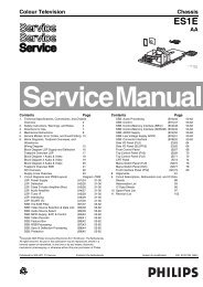
REPLACEMENT PARTS LIST<br />
Important Safety Notice<br />
Components Identified by mark have special characteristics important for safety.<br />
* When replacing any of these components, use only manufacturers specified parts.<br />
In case of ordering these spare parts, please always add the complete Model-Type<br />
number to your order.<br />
Cct Ref Parts Number Description<br />
Cct Ref Parts Number Description<br />
COMMON PARTS<br />
EXPLODED VIEW<br />
1 4852089314 MASK FRONT<br />
2 4852170214 COVER BACK<br />
3 4852825211 DOOR<br />
4 4854868711 BUTTON POWER<br />
5 4855624800 MARK BRAND<br />
6 4856017354 SCREW CRT FIX<br />
7 4859724930 TUNER VARACTOR<br />
8 4859810593 PCB MAIN<br />
9 4859810593-C PCB CRT<br />
10 4859906210 POWER CORD<br />
11 48A8309000 SPEAKER SYSTEM<br />
12 50H0000277 FBT<br />
13 58G0000149 COIL DEGAUSSING<br />
14 A68EPD10X22 CRT<br />
15 EUR7628030 REMOTE CONTROL<br />
MISCELLANEOUS COMPONENTS<br />
M481A 4856716000 POWER BUTTON SPRING<br />
M501 4855061600 DECO CTRL<br />
M551 4855553500 DECO SENSOR<br />
M791 LA701<br />
DOOR LOCK<br />
I.C.s<br />
I301 TDA8358J IC VERTICAL<br />
I602 TDA8946J IC AUDIO<br />
I703 TSOP1238WI1 PREAMP<br />
I801 STR-W6754 IC POWER<br />
I804 KP1010C PHOTO COUPLER<br />
I806 DP130<br />
IC ERROR AMP<br />
I820 L7805CV<br />
IC REGULATOR<br />
I822 KIA78R08API IC REGULATOR<br />
I823 LD1117V33 IC REGULATOR<br />
I824 L7805CV<br />
IC REGULATOR<br />
I901 TDA6107AJ IC VIDEO<br />
FUSES<br />
F801 5FSCB4022R FUSE 4A250V<br />
DIODES<br />
D101 DBAT85<br />
DIODE<br />
D102 BA282<br />
DIODE<br />
D313 1N4937G DIODE<br />
D403 DBY228<br />
DIODE<br />
D404 DBYW76<br />
DIODE<br />
D405 1N4937G DIODE<br />
D407 RGP15J<br />
DIODE<br />
D408 RGP15J<br />
DIODE<br />
D410 1N4004S<br />
DIODE<br />
D411 1N4004S<br />
DIODE<br />
D414 1N4004S<br />
DIODE<br />
D450 1N4937G DIODE<br />
D501 DBAT85<br />
DIODE<br />
D503 DTZX3V9B DIODE<br />
D504 DTZX5V6B DIODE<br />
D520 1N4148<br />
DIODE<br />
D521 1N4148<br />
DIODE<br />
D522 DTZX3V9B DIODE<br />
D523 DTZX3V9B DIODE<br />
D601 1N4148<br />
DIODE<br />
D602 1N4148<br />
DIODE<br />
D710 DTZX5V6B DIODE<br />
D801 LT2A05G DIODE<br />
D802 LT2A05G DIODE<br />
D803 LT2A05G DIODE<br />
D804 LT2A05G DIODE<br />
D805 1N4937G DIODE<br />
D806 1N4937G DIODE<br />
D807 1N4937G DIODE<br />
D808 DUZ6R8BM DIODE ZENER<br />
D811 DTZX5V1B DIODE<br />
D820 DBYW76<br />
DIODE<br />
D824 DTZX5V1B DIODE<br />
D825 1N4148<br />
DIODE<br />
D830 1N4937G DIODE<br />
D831 1N4937G DIODE<br />
D860 RGP30J<br />
DIODE<br />
D904 DBAV21<br />
DIODE<br />
D905 DBAV21<br />
DIODE<br />
D906 DBAV21<br />
DIODE<br />
D997 LT2A05G DIODE<br />
DA01 1N4148<br />
DIODE<br />
DA02 DTZX5V6B DIODE<br />
DA03 1N4148<br />
DIODE<br />
DA04 DTZX5V6B DIODE<br />
DA06 DTZX5V6B DIODE<br />
DA08 DTZX5V6B DIODE<br />
DA09 DTZX5V6B DIODE<br />
DA10 DTZX5V6B DIODE<br />
DA11 DTZX5V6B DIODE<br />
DA13 DTZX5V6B DIODE<br />
DA14 DTZX5V6B DIODE<br />
DA15 DTZX5V6B DIODE<br />
DA20 DTZX5V6B DIODE<br />
DA21 DTZX5V6B DIODE<br />
DA22 DTZX5V6B DIODE<br />
I805 DTZX33B DIODE ZENER<br />
10
Cct Ref Parts Number Description<br />
Cct Ref Parts Number Description<br />
TRANSISTORS<br />
Q120 2SC5343Y<br />
Q401 2SD2578<br />
Q402 2SD1207<br />
Q501 2SC5343Y<br />
Q502 2SA1980Y<br />
Q503 2SC5343Y<br />
Q504 2SA1980Y<br />
Q506 2SC5343Y<br />
Q508 2SC5343Y<br />
Q513 2SA1980Y<br />
Q515 H2N7000<br />
Q601 2SC5343Y<br />
Q602 2SA1980Y<br />
Q807 KSA1013Y<br />
Q809 2SC5343Y<br />
Q810 2SC5343Y<br />
Q812 KTC3203-Y<br />
Q813 2SA1980Y<br />
Q814 2SC5343Y<br />
Q815 2SA1980Y<br />
Q816 2SC5343Y<br />
TRANSFORMERS<br />
T401 TD-19A1<br />
T801 50M4242C7-<br />
COILS<br />
L101 5CPZ100K02<br />
L350 5CPZ109K04<br />
L351 5CPZ109K04<br />
L401 58H0000041<br />
L402 58C7070085<br />
L505 PZ479K02<br />
L506 PZ479K02<br />
L507 PZ479K02<br />
L508 PZ479K02<br />
L509 PZ479K02<br />
L510 PZ479K02<br />
L512 PZ479K02<br />
L513 PZ479K02<br />
L514 5CPZ100K04<br />
L515 5CPZ100K02<br />
L516 PZ479K02<br />
L517 5CPZ479K04<br />
L518 5CPZ479K04<br />
L519 5CPZ479K04<br />
L523 PZ479K02<br />
L650 5MC0000100<br />
L801 5MC0000100<br />
L802 58CX430599<br />
L803 5MC0000100<br />
R713 5CPZ560K02<br />
FILTERS<br />
LF801 5PLF24A3<br />
Z101 K3953M<br />
Z102 5PK9650M--<br />
Z601 5PEFST471Y<br />
Z602 5PEFST471Y<br />
Z603 5PEFST471Y<br />
Z604 5PEFST471Y<br />
Z605 5PEFST471Y<br />
Z606 5PEFST471Y<br />
Z607 5PEFST471Y<br />
Z608 5PEFST471Y<br />
Z609 5PEFST471Y<br />
Z610 5PEFST471Y<br />
TRANSISTOR<br />
TRANSISTOR<br />
TRANSISTOR<br />
TRANSISTOR<br />
TRANSISTOR<br />
TRANSISTOR<br />
TRANSISTOR<br />
TRANSISTOR<br />
TRANSISTOR<br />
TRANSISTOR<br />
TRANSISTOR<br />
TRANSISTOR<br />
TRANSISTOR<br />
TRANSISTOR<br />
TRANSISTOR<br />
TRANSISTOR<br />
TRANSISTOR<br />
TRANSISTOR<br />
TRANSISTOR<br />
TRANSISTOR<br />
TRANSISTOR<br />
TRANSFORMER DRIVE<br />
TRANSFORMER SMPS<br />
PEAKING COIL<br />
COIL PEAKING<br />
COIL PEAKING<br />
COIL H-LINEARITY<br />
COIL CHOKE<br />
PEAKING COIL<br />
PEAKING COIL<br />
PEAKING COIL<br />
PEAKING COIL<br />
PEAKING COIL<br />
PEAKING COIL<br />
PEAKING COIL<br />
PEAKING COIL<br />
PEAKING COIL<br />
PEAKING COIL<br />
PEAKING COIL<br />
COIL PEAKING<br />
COIL PEAKING<br />
COIL PEAKING<br />
PEAKING COIL<br />
COIL BEAD<br />
COIL BEAD<br />
COIL CHOKE<br />
COIL BEAD<br />
PEAKING COIL<br />
FILTER LINE<br />
FILTER SAW<br />
FILTER SAW<br />
FILTER EMI<br />
FILTER EMI<br />
FILTER EMI<br />
FILTER EMI<br />
FILTER EMI<br />
FILTER EMI<br />
FILTER EMI<br />
FILTER EMI<br />
FILTER EMI<br />
FILTER EMI<br />
Z611<br />
Z612<br />
CRYSTALS<br />
X501<br />
RESISTORS<br />
5PEFST471Y<br />
5PEFST471Y<br />
5XJ24R576E<br />
FILTER EMI<br />
FILTER EMI<br />
CRYSTAL QUARTZ<br />
J7 ERD25TJ101 CARBON 0.25W 5% 100 Ω<br />
J25 ERD25TJ101 CARBON 0.25W 5% 100 Ω<br />
J26 ERD25TJ101 CARBON 0.25W 5% 100 Ω<br />
J50 ERD25TJ101 CARBON 0.25W 5% 100 Ω<br />
J76 ERD25TJ202 CARBON 0.25W 5% 2K Ω<br />
J83 ERD25TJ101 CARBON 0.25W 5% 100 Ω<br />
J84 ERD25TJ101 CARBON 0.25W 5% 100 Ω<br />
R103 ERD25TJ393 CARBON 0.25W 5% 39K Ω<br />
R104 ERD25TJ683 CARBON 0.25W 5% 68K Ω<br />
R105 ERD25TJ103 CARBON 0.25W 5% 10K Ω<br />
R106 ERD25TJ101 CARBON 0.25W 5% 100 Ω<br />
R107 ERD25TJ101 CARBON 0.25W 5% 100 Ω<br />
R114 ERD25TJ473 CARBON 0.25W 5% 47K Ω<br />
R115 ERD25TJ101 CARBON 0.25W 5% 100 Ω<br />
R120 ERD25TJ101 CARBON 0.25W 5% 100 Ω<br />
R131 ERD25TJ472 CARBON 0.25W 5% 4K7 Ω<br />
R310 ERD25TJ471 CARBON 0.25W 5% 470 Ω<br />
R311 ERD25TJ471 CARBON 0.25W 5% 470 Ω<br />
R331 ERDS1TJ201 CARBON 0.5W 5% 200 Ω<br />
R340 ERD25TJ473 CARBON 0.25W 5% 47K Ω<br />
R350 RN-AZ2201F METAL 0.17W - 2K2 Ω<br />
R351 RN-AZ2201F METAL 0.17W - 2K2 Ω<br />
R370 ERD25TJ159 CARBON 0.25W 5% 1.5 Ω<br />
R394 ERD25TJ272 CARBON 0.25W 5% 2K7 Ω<br />
R395 ERD25TJ394 CARBON 0.25W 5% 390K Ω<br />
R396 ERD25TJ103 CARBON 0.25W 5% 10K Ω<br />
R397 ERD25TJ823 CARBON 0.25W 5% 82K Ω<br />
R398 RS02Y129JS METAL 2W - 1R2 Ω<br />
R399 RS02Y120JS METAL 2W - 12 Ω<br />
R401 ERD25TJ272 CARBON 0.25W 5% 2K7 Ω<br />
R402 ERD25TJ220 CARBON 0.25W 5% 22 Ω<br />
R403 ERD25TJ102 CARBON 0.25W 5% 1K Ω<br />
R404 ERD25TJ109 CARBON 0.25W 5% 1 Ω<br />
R405 ERD25TJ102 CARBON 0.25W 5% 1K Ω<br />
R406 RS02Y471JS METAL 2W - 470 Ω<br />
R407 ERD25TJ182 CARBON 0.25W 5% 1K8 Ω<br />
R415 RN02B112JS METAL 2W - 1K1 Ω<br />
R420 ERDS1TJ103 CARBON 0.5W 5% 10K Ω<br />
R422 ERD25TJ102 CARBON 0.25W 5% 1K Ω<br />
R423 ERD25TJ392 CARBON 0.25W 5% 3K9 Ω<br />
R444 RS02Y478JS METAL 2W - R47 Ω<br />
R450 ERG2FJ473 METAL 2W 5% 47K Ω<br />
R451 ERG2FJ473 METAL 2W 5% 47K Ω<br />
R500 ERD25TJ101 CARBON 0.25W 5% 100 Ω<br />
R501 ERD25TJ332 CARBON 0.25W 5% 3K3 Ω<br />
R502 ERD25TJ332 CARBON 0.25W 5% 3K3 Ω<br />
R503 ERD25TJ102 CARBON 0.25W 5% 1K Ω<br />
R504 ERD25TJ152 CARBON 0.25W 5% 1K5 Ω<br />
R505 ERD25TJ101 CARBON 0.25W 5% 100 Ω<br />
R506 ERD25TJ103 CARBON 0.25W 5% 10K Ω<br />
R507 ERD25TJ332 CARBON 0.25W 5% 3K3 Ω<br />
R508 ERD25TJ332 CARBON 0.25W 5% 3K3 Ω<br />
R510 ERD25TJ103 CARBON 0.25W 5% 10K Ω<br />
R511 ERD25TJ103 CARBON 0.25W 5% 10K Ω<br />
R512 ERD25TJ101 CARBON 0.25W 5% 100 Ω<br />
R513 ERD25TJ101 CARBON 0.25W 5% 100 Ω<br />
R514 ERD25TJ101 CARBON 0.25W 5% 100 Ω<br />
R515 ERD25TJ101 CARBON 0.25W 5% 100 Ω<br />
R516 ERD25TJ153 CARBON 0.25W 5% 15K Ω<br />
R517 ERD25TJ101 CARBON 0.25W 5% 100 Ω<br />
R518 ERD25TJ101 CARBON 0.25W 5% 100 Ω<br />
11
Cct Ref Parts Number Description<br />
Cct Ref Parts Number Description<br />
R519 ERD25TJ102 CARBON 0.25W 5% 1K Ω<br />
R527 ERD25TJ101 CARBON 0.25W 5% 100 Ω<br />
R528 ERD25TJ101 CARBON 0.25W 5% 100 Ω<br />
R529 ERD25TJ101 CARBON 0.25W 5% 100 Ω<br />
R530 ERD25TJ221 CARBON 0.25W 5% 220 Ω<br />
R532 ERD25TJ102 CARBON 0.25W 5% 1K Ω<br />
R534 ERD25TJ472 CARBON 0.25W 5% 4K7 Ω<br />
R537 ERD25TJ123 CARBON 0.25W 5% 12K Ω<br />
R538 ERD25TJ101 CARBON 0.25W 5% 100 Ω<br />
R539 ERD25TJ471 CARBON 0.25W 5% 470 Ω<br />
R540 ERD25TJ471 CARBON 0.25W 5% 470 Ω<br />
R541 RN-AZ3902F METAL 0.17W - 39K Ω<br />
R542 ERD25TJ682 CARBON 0.25W 5% 6K8 Ω<br />
R543 ERD25TJ222 CARBON 0.25W 5% 2K2 Ω<br />
R544 ERD25TJ222 CARBON 0.25W 5% 2K2 Ω<br />
R545 ERD25TJ473 CARBON 0.25W 5% 47K Ω<br />
R546 ERD25TJ681 CARBON 0.25W 5% 680 Ω<br />
R547 ERD25TJ563 CARBON 0.25W 5% 56K Ω<br />
R551 ERD25TJ823 CARBON 0.25W 5% 82K Ω<br />
R552 ERD25TJ103 CARBON 0.25W 5% 10K Ω<br />
R553 ERD25TJ103 CARBON 0.25W 5% 10K Ω<br />
R554 ERD25TJ103 CARBON 0.25W 5% 10K Ω<br />
R555 ERD25TJ103 CARBON 0.25W 5% 10K Ω<br />
R556 ERD25TJ101 CARBON 0.25W 5% 100 Ω<br />
R557 ERD25TJ101 CARBON 0.25W 5% 100 Ω<br />
R558 ERD25TJ391 CARBON 0.25W 5% 390 Ω<br />
R559 ERD25TJ222 CARBON 0.25W 5% 2K2 Ω<br />
R560 ERD25TJ222 CARBON 0.25W 5% 2K2 Ω<br />
R561 ERD25TJ101 CARBON 0.25W 5% 100 Ω<br />
R562 ERD25TJ101 CARBON 0.25W 5% 100 Ω<br />
R563 ERD25TJ101 CARBON 0.25W 5% 100 Ω<br />
R564 ERD25TJ101 CARBON 0.25W 5% 100 Ω<br />
R565 ERD25TJ154 CARBON 0.25W 5% 150K Ω<br />
R566 ERD25TJ103 CARBON 0.25W 5% 10K Ω<br />
R567 ERD25TJ103 CARBON 0.25W 5% 10K Ω<br />
R568 ERD25TJ103 CARBON 0.25W 5% 10K Ω<br />
R569 ERD25TJ103 CARBON 0.25W 5% 10K Ω<br />
R571 ERD25TJ102 CARBON 0.25W 5% 1K Ω<br />
R572 ERD25TJ103 CARBON 0.25W 5% 10K Ω<br />
R573 ERD25TJ103 CARBON 0.25W 5% 10K Ω<br />
R574 ERD25TJ103 CARBON 0.25W 5% 10K Ω<br />
R575 ERD25TJ103 CARBON 0.25W 5% 10K Ω<br />
R576 ERD25TJ102 CARBON 0.25W 5% 1K Ω<br />
R577 ERD25TJ102 CARBON 0.25W 5% 1K Ω<br />
R578 ERD25TJ102 CARBON 0.25W 5% 1K Ω<br />
R579 ERD25TJ101 CARBON 0.25W 5% 100 Ω<br />
R580 ERD25TJ183 CARBON 0.25W 5% 18K Ω<br />
R581 ERD25TJ101 CARBON 0.25W 5% 100 Ω<br />
R582 ERD25TJ101 CARBON 0.25W 5% 100 Ω<br />
R583 ERD25TJ101 CARBON 0.25W 5% 100 Ω<br />
R584 ERD25TJ101 CARBON 0.25W 5% 100 Ω<br />
R585 ERD25TJ101 CARBON 0.25W 5% 100 Ω<br />
R586 ERD25TJ101 CARBON 0.25W 5% 100 Ω<br />
R587 ERD25TJ101 CARBON 0.25W 5% 100 Ω<br />
R588 ERD25TJ102 CARBON 0.25W 5% 1K Ω<br />
R589 ERD25TJ102 CARBON 0.25W 5% 1K Ω<br />
R590 ERD25TJ334 CARBON 0.25W 5% 330K Ω<br />
R598 ERD25TJ182 CARBON 0.25W 5% 1K8 Ω<br />
R599 ERD25TJ224 CARBON 0.25W 5% 220K Ω<br />
R601 ERD25TJ152 CARBON 0.25W 5% 1K5 Ω<br />
R602 ERD25TJ104 CARBON 0.25W 5% 100K Ω<br />
R608 ERDS1TJ151 CARBON 0.5W 5% 150 Ω<br />
R609 ERDS1TJ151 CARBON 0.5W 5% 150 Ω<br />
R610 ERD25TJ103 CARBON 0.25W 5% 10K Ω<br />
R611 ERD25TJ563 CARBON 0.25W 5% 56K Ω<br />
R612 ERD25TJ563 CARBON 0.25W 5% 56K Ω<br />
R650 ERD25TJ473 CARBON 0.25W 5% 47K Ω<br />
R660 ERD25TJ473 CARBON 0.25W 5% 47K Ω<br />
R661 RN-AZ1202F METAL 0.17W 1% 12K Ω<br />
R662 RN-AZ1202F METAL 0.17W 1% 12K Ω<br />
R700 ERDS1TJ332 CARBON 0.5W 5% 3K3 Ω<br />
R720 ERD25TJ122 CARBON 0.25W 5% 1K2 Ω<br />
R721 ERD25TJ181J CARBON 0.25W 5% 180 Ω<br />
R722 ERD25TJ221 CARBON 0.25W 5% 220 Ω<br />
R723 ERD25TJ331 CARBON 0.25W 5% 330 Ω<br />
R724 ERD25TJ471 CARBON 0.25W 5% 470 Ω<br />
R801 DDB7R0M290 POSISTOR - - - Ω<br />
R803 RW02Y508FS WOUND 2W - R5 Ω<br />
R804 ERD25TJ220 CARBON 0.25W 5% 22 Ω<br />
R805 ERDS1TJ104 CARBON 0.5W 5% 100K Ω<br />
R806 RS02Y278JS METAL 2W - R27 Ω<br />
R807 ERD25TJ221 CARBON 0.25W 5% 220 Ω<br />
R808 ERD25TJ182 CARBON 0.25W 5% 1K8 Ω<br />
R809 ERD25TJ102 CARBON 0.25W 5% 1K Ω<br />
R810 ERD25TJ220 CARBON 0.25W 5% 22 Ω<br />
R811 ERDS1TJ825 CARBON 0.5W 5% 8M2 Ω<br />
R812 ERD25TJ473 CARBON 0.25W 5% 47K Ω<br />
R813 ERD25TJ473 CARBON 0.25W 5% 47K Ω<br />
R814 ERD25TJ472 CARBON 0.25W 5% 4K7 Ω<br />
R815 ERD25TJ472 CARBON 0.25W 5% 4K7 Ω<br />
R817 ERD25TJ473 CARBON 0.25W 5% 47K Ω<br />
R818 ERD25TJ683 CARBON 0.25W 5% 68K Ω<br />
R819 RX07C339JF SOLID 7W - 3R3 Ω<br />
R820 ERD25TJ363 CARBON 0.25W 5% 36K Ω<br />
R821 ERD25TJ563 CARBON 0.25W 5% 56K Ω<br />
R822 RN02B510JS METAL 2W - 51 Ω<br />
R823 ERD25TJ102 CARBON 0.25W 5% 1K Ω<br />
R824 RN02B510JS METAL 2W - 51 Ω<br />
R827 ERD25TJ103 CARBON 0.25W 5% 10K Ω<br />
R828 ERDS2TJ752 CARBON 0.25W 5% 7K5 Ω<br />
R829 ERD25TJ103 CARBON 0.25W 5% 10K Ω<br />
R830 ERD25TJ101 CARBON 0.25W 5% 100 Ω<br />
R831 ERD25TJ472 CARBON 0.25W 5% 4K7 Ω<br />
R832 ERD25TJ473 CARBON 0.25W 5% 47K Ω<br />
R833 ERDS1TJ105 CARBON 0.5W 5% 1M Ω<br />
R834 ERD25TJ470 CARBON 0.25W 5% 47 Ω<br />
R840 ERD25TJ472 CARBON 0.25W 5% 4K7 Ω<br />
R841 RS02Y479JS METAL 2W - 4R7 Ω<br />
R842 RS02Y240JS METAL 2W - 24 Ω<br />
R850 RS02Y479JS METAL 2W - 4R7 Ω<br />
R870 ERD25TJ102 CARBON 0.25W 5% 1K Ω<br />
R901 ERD25TJ561 CARBON 0.25W 5% 560 Ω<br />
R910 ERD25TJ101 CARBON 0.25W 5% 100 Ω<br />
R911 ERD25TJ101 CARBON 0.25W 5% 100 Ω<br />
R912 ERD25TJ101 CARBON 0.25W 5% 100 Ω<br />
R913 ERDS1TJ102 CARBON 0.5W 5% 1K Ω<br />
R914 ERDS1TJ102 CARBON 0.5W 5% 1K Ω<br />
R915 ERDS1TJ102 CARBON 0.5W 5% 1K Ω<br />
R920 RS01Y229J FILM<br />
1W 5% 2R2 Ω<br />
R921 ERD25TJ221 CARBON 0.25W 5% 220 Ω<br />
R922 ERD25TJ221 CARBON 0.25W 5% 220 Ω<br />
R923 ERD25TJ221 CARBON 0.25W 5% 220 Ω<br />
R996 ERDS1TJ105 CARBON 0.5W 5% 1M Ω<br />
R997 ERDS1TJ102 CARBON 0.5W 5% 1K Ω<br />
RA02 ERD25TJ101 CARBON 0.25W 5% 100 Ω<br />
RA03 ERD25TJ101 CARBON 0.25W 5% 100 Ω<br />
RA04 ERD25TJ101 CARBON 0.25W 5% 100 Ω<br />
RA05 ERD25TJ103 CARBON 0.25W 5% 10K Ω<br />
RA06 ERD25TJ750 CARBON 0.25W 5% 75 Ω<br />
RA07 ERD25TJ332 CARBON 0.25W 5% 3K3 Ω<br />
RA08 ERD25TJ750 CARBON 0.25W 5% 75 Ω<br />
RA09 ERD25TJ750 CARBON 0.25W 5% 75 Ω<br />
12
Cct Ref Parts Number Description<br />
Cct Ref Parts Number Description<br />
RA10 ERD25TJ680 CARBON 0.25W 5% 68 Ω<br />
RA11 ERD25TJ750 CARBON 0.25W 5% 75 Ω<br />
RA12 ERD25TJ102 CARBON 0.25W 5% 1K Ω<br />
RA13 ERD25TJ222 CARBON 0.25W 5% 2K2 Ω<br />
RA14 ERD25TJ220 CARBON 0.25W 5% 22 Ω<br />
RA15 ERD25TJ750 CARBON 0.25W 5% 75 Ω<br />
RA16 ERD25TJ750 CARBON 0.25W 5% 75 Ω<br />
RA17 ERD25TJ103 CARBON 0.25W 5% 10K Ω<br />
RA18 ERD25TJ332 CARBON 0.25W 5% 3K3 Ω<br />
RA19 ERD25TJ750 CARBON 0.25W 5% 75 Ω<br />
RA23 ERD25TJ220 CARBON 0.25W 5% 22 Ω<br />
RA24 ERD25TJ222 CARBON 0.25W 5% 2K2 Ω<br />
RA25 ERD25TJ102 CARBON 0.25W 5% 1K Ω<br />
RA29 ERD25TJ101 CARBON 0.25W 5% 100 Ω<br />
RA32 ERD25TJ680 CARBON 0.25W 5% 68 Ω<br />
RA35 ERD25TJ750 CARBON 0.25W 5% 75 Ω<br />
CAPACITORS<br />
C102 ECEA1ES470 ELECT 25V 47µF<br />
C103 ECCR1H102J CERAMIC 50V 1nF<br />
C104 ECCR1H102J CERAMIC 50V 1nF<br />
C106 ECEA1H220 ELECT 50V 22µF<br />
C107 ECKR1H470 CERAMIC 50V 47pF<br />
C108 ECKR1H470 CERAMIC 50V 47pF<br />
C120 ECCR1H102J CERAMIC 50V 1nF<br />
C121 ECEA1H100 ELECT 50V 10µF<br />
C122 ECEA1H100 ELECT 50V 10µF<br />
C123 ECKC1H103J CERAMIC 50V 10nF<br />
C305 ECEA1ES221 ELECT 25V 220µF<br />
C313 CMXM2A104J MYLAR 100V 100nF<br />
C315 ECA2AHG470 ELECT 100V 47µF<br />
C320 CBXF1H104Z CERAMIC 50V 0.1µF<br />
C350 CMXM2A683J FILM 100V 68nF<br />
C351 CMXM2A473J MYLAR 100V 47nF<br />
C370 ECCR1H473J CERAMIC 50V 47nF<br />
C401 ECEA1H101 ELECT 50V 100µF<br />
C402 CMYH3C752J FILM 1.6kV 7.5nF<br />
C404 CMYH3C622J MYLAR 1K6V 6200pF<br />
C408 ECWF2364JBB FILM 250V 360nF<br />
C412 ECEA2CS339 ELECT 160V 3.3µF<br />
C414 CMXM2A104J MYLAR 100V 100nF<br />
C415 ECA2EM4R7B ELECT 250V 4.7µF<br />
C418 ECCR1H102J CERAMIC 50V 1nF<br />
C420 ECCR2H222J CERAMIC 500V 2.2nF<br />
C421 ECCR1H473J CERAMIC 50V 47nF<br />
C430 CCYR3D681K CERAMIC 2kV 680pF<br />
C431 CMXB2G472J FILM 400V 4.7nF<br />
C440 ECQM4223JZB FILM 400V 22nF<br />
C499 CEYD1H689W ELECT 50V 6.8µF<br />
C501 ECEA1CS470 ELECT 16V 47µF<br />
C502 ECEA1CS470 ELECT 16V 47µF<br />
C503 ECCR1H102J CERAMIC 50V 1nF<br />
C504 ECCR1H102J CERAMIC 50V 1nF<br />
C505 CMXL1J224J FILM<br />
63V 0.22µF<br />
C507 CMXL1J224J FILM<br />
63V 0.22µF<br />
C508 ECEA1CS470 ELECT 16V 47µF<br />
C509 CMXL1J224J FILM<br />
63V 0.22µF<br />
C510 ECEA1ES101 ELECT 25V 100µF<br />
C511 ECCR1H102J CERAMIC 50V 1nF<br />
C512 CBZF1H104Z CERAMIC 50V 100nF<br />
C513 CMXL1J224J FILM<br />
63V 0.22µF<br />
C514 ECCR1H102J CERAMIC 50V 1nF<br />
C515 CMXL1J224J FILM<br />
63V 0.22µF<br />
C516 CMXL1J224J FILM<br />
63V 0.22µF<br />
C517 ECEA1CS101 ELECT 16V 100µF<br />
C518 CBXF1H104Z CERAMIC 50V 0.1µF<br />
C519 CMXL1J224J FILM<br />
63V 0.22µF<br />
C520 ECEA1H100 ELECT 50V 10µF<br />
C521 ECCR1H222J CERAMIC 50V 2.2nF<br />
C522 CBXF1H104Z CERAMIC 50V 0.1µF<br />
C523 ECCR1H102J CERAMIC 50V 1nF<br />
C524 ECQB1682JFB FILM 100V 6.8nF<br />
C525 ECEA1H479 ELECT 50V 4.7µF<br />
C526 CMXL1J224J FILM<br />
63V 0.22µF<br />
C527 ECEA1H100 ELECT 50V 10µF<br />
C528 ECCR1H223J CERAMIC 50V 22nF<br />
C529 ECQV1J154JM3 FILM<br />
63V 150nF<br />
C530 ECKC1H101J CERAMIC 50V 100pF<br />
C531 ECKC1H103J CERAMIC 50V 10nF<br />
C532 ECCR1H102J CERAMIC 50V 1nF<br />
C533 ECCR1H102J CERAMIC 50V 1nF<br />
C534 ECEA1H229 ELECT 50V 2.2µF<br />
C535 ECQV1J474JMW FILM<br />
63V 470nF<br />
C536 ECQV1J474JMW FILM<br />
63V 470nF<br />
C537 ECEA1H229 ELECT 50V 2.2µF<br />
C538 ECEA1H229 ELECT 50V 2.2µF<br />
C539 CMXM2A332J FILM 100V 3.3nF<br />
C540 CMXL1J104J MYLAR 63V 100nF<br />
C541 CBZF1H104Z CERAMIC 50V 100nF<br />
C542 ECEA1H100 ELECT 50V 10µF<br />
C543 ECEA1H229 ELECT 50V 2.2µF<br />
C544 CBZF1H104Z CERAMIC 50V 100nF<br />
C545 ECEA1H229 ELECT 50V 2.2µF<br />
C546 CBZF1H104Z CERAMIC 50V 100nF<br />
C547 ECEA1H100 ELECT 50V 10µF<br />
C548 ECEA1H100 ELECT 50V 10µF<br />
C549 ECQV1J474JMW FILM<br />
63V 470nF<br />
C550 ECKC1H103J CERAMIC 50V 10nF<br />
C551 CBZF1H104Z CERAMIC 50V 100nF<br />
C552 ECQV1J474JMW FILM<br />
63V 470nF<br />
C553 ECQV1J474JMW FILM<br />
63V 470nF<br />
C554 ECQV1J474JMW FILM<br />
63V 470nF<br />
C555 ECCR1H102J CERAMIC 50V 1nF<br />
C556 ECCR1H102J CERAMIC 50V 1nF<br />
C557 CBZF1H104Z CERAMIC 50V 100nF<br />
C558 CBXF1H104Z CERAMIC 50V 0.1µF<br />
C560 ECEA1H229 ELECT 50V 2.2µF<br />
C561 ECEA1H229 ELECT 50V 2.2µF<br />
C563 ECEA1H100 ELECT 50V 10µF<br />
C564 CBZF1H104Z CERAMIC 50V 100nF<br />
C565 CBZF1H104Z CERAMIC 50V 100nF<br />
C566 CBZF1H104Z CERAMIC 50V 100nF<br />
C567 ECEA1H100 ELECT 50V 10µF<br />
C568 CBXF1H104Z CERAMIC 50V 0.1µF<br />
C569 ECEA1ES470 ELECT 25V 47µF<br />
C574 CMXL1J224J FILM<br />
63V 0.22µF<br />
C575 ECCR1H102J CERAMIC 50V 1nF<br />
C576 CMXL1J224J FILM<br />
63V 0.22µF<br />
C577 ECEA1CS101 ELECT 16V 100µF<br />
C578 CBZF1H104Z CERAMIC 50V 100nF<br />
C579 ECCR1H102J CERAMIC 50V 1nF<br />
C581 CMXL1J224J FILM<br />
63V 0.22µF<br />
C582 ECEA1CS101 ELECT 16V 100µF<br />
C587 ECCR1H102J CERAMIC 50V 1nF<br />
C589 ECKC1H472J CERAMIC 50V 4.7nF<br />
C590 CBZF1H104Z CERAMIC 50V 100nF<br />
C591 CMXL1J224J FILM<br />
63V 0.22µF<br />
C592 ECKC1H103J CERAMIC 50V 10nF<br />
C602 ECEA1ES470 ELECT 25V 47µF<br />
C603 ECEA1H228 ELECT 50V 0.22µF<br />
C604 ECEA1ES102 ELECT 25V 1000µF<br />
C608 ECCR1H222J CERAMIC 50V 2.2nF<br />
C609 ECCR1H222J CERAMIC 50V 2.2nF<br />
13
Cct Ref Parts Number Description<br />
Cct Ref Parts Number Description<br />
C625 ECEA1H479 ELECT 50V 4.7µF<br />
C660 ECEA1H100 ELECT 50V 10µF<br />
C661 CMXM2A224J FILM 100V 0.22µF<br />
C662 CMXM2A224J FILM 100V 0.22µF<br />
C665 ECCR1H472J CERAMIC 50V 4.7nF<br />
C666 CBXF1H104Z CERAMIC 50V 0.1µF<br />
C667 ECCR1H472J CERAMIC 50V 4.7nF<br />
C668 CMXM2A224J FILM 100V 0.22µF<br />
C669 CMXM2A224J FILM 100V 0.22µF<br />
C690 ECEA1H479 ELECT 50V 4.7µF<br />
C691 ECEA1H479 ELECT 50V 4.7µF<br />
C770 ECEA1CS101 ELECT 16V 100µF<br />
C801 CL1UC3474M CERAMIC 250V 470nF<br />
C803 ECCR3A472J CERAMIC 1kV 4.7nF<br />
C804 ECCR3A472J CERAMIC 1kV 4.7nF<br />
C805 ECA2GM181B ELECT 400V 180µF<br />
C806 CCXR3A102K CERAMIC 1kV 1nF<br />
C807 ECEA1H109 ELECT 50V 1µF<br />
C809 ECKC1H101J CERAMIC 50V 100pF<br />
C810 ECEA1H220 ELECT 50V 22µF<br />
C811 CMXM2A473J MYLAR 100V 47nF<br />
C812 CH1BFE472M CERAMIC 400V 4.7nF<br />
C813 CEYF2E470V ELECT 250V 47µF<br />
C814 ECA2EM101 ELECT 250V 100µF<br />
C820 CCYR3D221K CERAMIC 2kV 220pF<br />
C823 ECEA1ES471 ELECT 25V 470µF<br />
C830 ECEA1H479 ELECT 50V 4.7µF<br />
C831 ECEA1H330 ELECT 50V 33µF<br />
C833 CCXB1H821K CERAMIC 50V 820pF<br />
C834 ECCR1H103J CERAMIC 50V 10nF<br />
C835 ECEA1ES470 ELECT 25V 47µF<br />
C840 ECEA1CS332 ELECT 16V 3300µF<br />
C844 ECEA1ES101 ELECT 25V 100µF<br />
C861 ECEA1ES102 ELECT 25V 1000µF<br />
C862 ECEA1ES101 ELECT 25V 100µF<br />
C863 ECEA1CS101 ELECT 16V 100µF<br />
C866 ECKC3A471J CERAMIC 1KV 470pF<br />
C901 ECCR1H221J CERAMIC 50V 220pF<br />
C905 ECA2EM4R7B ELECT 250V 4.7µF<br />
C965 ECKC3D102J CERAMIC 2KV 1nF<br />
C968 CMXL2E104K MYLAR 250V 100nF<br />
C997 ECA2EM100B ELECT 250V 10µF<br />
CA01 ECKC1H101J CERAMIC 50V 100pF<br />
CA02 ECKC1H101J CERAMIC 50V 100pF<br />
CA03 ECKC1H101J CERAMIC 50V 100pF<br />
CA04 ECKC1H101J CERAMIC 50V 100pF<br />
CA05 ECKC1H101J CERAMIC 50V 100pF<br />
CA06 ECKC1H101J CERAMIC 50V 100pF<br />
CA10 ECCR1H102J CERAMIC 50V 1nF<br />
CA28 ECCR1H102J CERAMIC 50V 1nF<br />
TERMINALS AND LINKS<br />
JP01 4859102130<br />
JPA1 4859200401<br />
JPA2 4859200401<br />
JPA3 4859108450<br />
SCT1 4859303530<br />
SWITCHES<br />
HEADPHONE SOCKET<br />
AV TERMINAL<br />
AV TERMINAL<br />
JACK PIN BOARD<br />
SOCKET CRT<br />
DIFFERENCES FOR MODEL TX--29PM1D<br />
EXPLODED VIEW<br />
16 DMP4502500 S/PLATE<br />
INSTRUCTION BOOKS<br />
. TQB0E0051A1M GERMAN<br />
. TQB0E0051C1M ITALIAN<br />
. TQB0E0051D1M FRENCH<br />
I.C.s<br />
I501 TDA21HD01-W IC MICOM FLASH<br />
I502 X24C29PM1D IC MEMORY<br />
DIFFERENCES FOR MODEL TX--29PM1F<br />
EXPLODED VIEW<br />
16 DMP4502600 S/PLATE<br />
INSTRUCTION BOOKS<br />
. TQB0E0052A1M GERMAN<br />
. TQB0E0052B1M DUTCH<br />
. TQB0E0052D1M FRENCH<br />
. TQB0E0052E1M SPANISH<br />
. TQB0E0052F1M SWEDISH<br />
. TQB0E0052G1M NORWEGIAN<br />
. TQB0E0052H1M FINNISH<br />
. TQB0E0052J1M PORTUGUESE<br />
. TQB0E0052K1M DANISH<br />
I.C.s<br />
I501 TDA21HD01-W IC MICOM FLASH<br />
I502 X24C29PM1F IC MEMORY<br />
DIFFERENCES FOR MODEL TX--29PM1P<br />
EXPLODED VIEW<br />
16 DMP4502700 S/PLATE<br />
INSTRUCTION BOOKS<br />
. TQB0E0053M1M BULGARIAN<br />
. TQB0E0053N1M ROMANIAN<br />
. TQB0E0053P1M POLISH<br />
. TQB0E0053Q1M HUNGARIAN<br />
. TQB0E0053R1M CZECH<br />
. TQB0E0053U1M ENGLISH<br />
. TQB0E0053W1M SLOVAKIAN<br />
I.C.s<br />
I501 TDA21HD01-E IC MICOM FLASH<br />
I502 X24C29PM1P IC MEMORY<br />
SW700<br />
SW701<br />
SW702<br />
SW703<br />
SW704<br />
SW801<br />
RELAYS<br />
Y801<br />
5S50101Z90<br />
5S50101Z90<br />
5S50101Z90<br />
5S50101Z90<br />
5S50101Z90<br />
5S40101143<br />
5SC0101003<br />
SWITCH<br />
SWITCH<br />
SWITCH<br />
SWITCH<br />
SWITCH<br />
SWITCH<br />
RELAY<br />
14
SCHEMATIC DIAGRAMS FOR MODELS<br />
TX-29PM1D, TX-29PM1F, TX-29PM1P<br />
(CP-521F CHASSIS)<br />
IMPORTANT SAFETY NOTICE<br />
Components identified by mark have special characteristics<br />
important for safety. When replacing any of these components, use<br />
only manufacturers' specified parts.<br />
NOTE<br />
1. RESISTOR<br />
All resistors are carbon ¼W resistor, unless marked otherwise.<br />
Unit of resistance is OHM ( ) (k=1,000, M=1,000,000)<br />
2. CAPACITORS<br />
All capacitors are ceramic 50V unless marked otherwise.<br />
Unit of capacitance is F unless otherwise stated.<br />
3. COIL<br />
Unit of inductance is H, unless otherwise stated.<br />
4. EARTH SYMBOL<br />
Chassis Earth (Cold)<br />
Line Earth (Hot)<br />
5. VOLTAGE MEASUREMENT<br />
Voltage is measured by a d.c. voltmeter.<br />
Measurement conditions are as follows:<br />
Power source a.c. 220V-240V, 50Hz<br />
Receiving Signal Colour Bar signal (RF)<br />
All customer controls Maximum position<br />
These schematic diagrams are the latest at time of printing and are subject to change without notice.<br />
REMARKS<br />
a. Do not touch the hot part, or the hot and cold parts at the same time, as you are liable to a shock hazard.<br />
b. Do not short circuit the hot and cold circuits as electrical components may be damaged.<br />
c. Do not connect an instrument, such as an oscilloscope, to the hot and cold circuits simultaneously as this may cause<br />
fuse failure. Connect the earth of the instruments to the earth connection of the circuit being measured.<br />
d. Make sure to disconnect the power plug before removing the chassis.<br />
NOTE<br />
1. The Power Supply Circuit contains a circuit area, which uses a separate power supply to isolate the earth connection.<br />
The circuit is defined by HOT and COLD indications in the schematic diagram. All circuits, except the Power Circuit, are<br />
COLD.<br />
15
CONDUCTOR VIEWS FOR MODELS<br />
TX-29PM1D, TX-29PM1F, TX-29PM1P<br />
MAIN-BOARD PTMPMSS29Y6FM<br />
TRAN'S D410 C4 D906 E2<br />
Q120 A1 D411 C4 D997 E1<br />
Q401 B5 D414 A5 DA01 B3<br />
Q402 B4 D450 B4 DA02 A2<br />
Q501 A1 D501 C1 DA03 A3<br />
Q502 A1 D503 D2 DA04 A2<br />
Q503 A3 D504 D2 DA06 A2<br />
Q504 A4 D520 C3 DA08 A2<br />
Q506 E4 D521 B3 DA09 A2<br />
Q508 B2 D522 D2 DA10 A2<br />
Q513 B3 D523 C2 DA11 A2<br />
Q514 D1 D601 D3 DA13 A3<br />
Q515 D1 D602 D3 DA14 A3<br />
Q601 D3 D707 E5 DA15 A3<br />
Q602 C3 D710 E4 DA20 E3<br />
Q807 C5 D801 D5 DA21 E3<br />
Q809 D4 D802 D5 DA22 E3<br />
Q810 E4 D803 D5<br />
Q812 C6 D804 D5 IC'S<br />
Q813 D2 D805 E4 I301 B4<br />
Q814 D3 D806 D4 I501 C2<br />
Q815 D1 D807 D5 I502 D1<br />
Q816 D1 D808 D4 I602 D3<br />
D811 E4 I703 E5<br />
DIODES D820 C5 I801 E5<br />
D101 A1 D824 C4 I804 D4<br />
D102 B2 D825 C6 I805 B3<br />
D313 A4 D826 C3 I806 D4<br />
D403 B5 D830 C4 I820 C3<br />
D404 B5 D831 C4 I822 C4<br />
D405 A5 D860 C4 I823 C4<br />
D407 A5 D904 E2 I824 D4<br />
D408 A5 D905 E2 I901 E2<br />
20 17