Create successful ePaper yourself
Turn your PDF publications into a flip-book with our unique Google optimized e-Paper software.
Mechanical Instructions <strong>LC7.1E</strong> PA 4. EN 9<br />
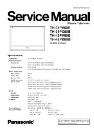
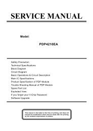
4.3.3 Keyboard Control Panel [E]<br />
1. Refer to next fig. “Keyboard control panel“.<br />
2. Remove the T10 Parker screws [1] from the shielding.<br />
3. Remove the shielding.<br />
4. Remove the T10 Parker screws [2] from the bracket.<br />
5. Remove the unit.<br />
6. Unplug connector(s).<br />
When defective, replace the whole unit.<br />
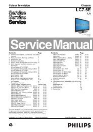
4.3.4 Side I/O Panel [D]<br />
1. Remove the bottom “speaker cover”, as described earlier.<br />
2. Refer to next fig. “Side I/O and IR/LED panel“.<br />
3. Remove T10 Parker screws [1] and take out the panel.<br />
When defective, replace the whole unit.<br />
1<br />
2<br />
Figure 4-6 Keyboard control panel [1/2]<br />
H_17000_010.eps<br />
260207<br />
Figure 4-8 Side I/O and IR/LED panel<br />
1<br />
H_17000_014.eps<br />
280207<br />
4.3.5 IR/LED Panel [J]<br />
1. Remove the bottom “speaker cover”, as described earlier.<br />
2. Refer to earlier fig. “Side I/O and IR/LED panel“.<br />
3. Release clip [2] and remove the board.<br />
4. Unplug connector(s).<br />
When defective, replace the whole unit.<br />
2<br />
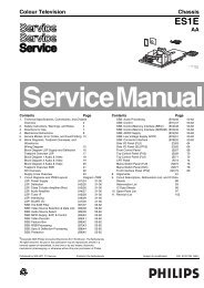
4.3.6 Speakers<br />
1. Remove the bottom “speaker cover”, as described earlier.<br />
2. Refer to fig. “Speakers“ below.<br />
3. Unplug connectors.<br />
4. Remove T10 Parker screws [1] and [2].<br />
5. Take out the speaker(s).<br />
H_17000_011.eps<br />
260207<br />
Figure 4-7 Keyboard control panel [2/2]<br />
1 2<br />
H_17000_013.eps<br />
260207<br />
Figure 4-9 Speakers