You also want an ePaper? Increase the reach of your titles
YUMPU automatically turns print PDFs into web optimized ePapers that Google loves.
EN 8<br />
4.<br />
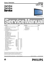
<strong>LC7.1E</strong> PA<br />
Mechanical Instructions<br />
4.2 Service Positions<br />
For easy servicing of this set, there are a few possibilities<br />
created:<br />
• The buffers from the packaging.<br />
• Foam bars (created for Service).<br />
• Aluminium service stands (created for Service).<br />
4.2.1 Foam Bars<br />
1<br />
4.3 Assy/Panel Removal<br />
4.3.1 Rear Cover<br />
Warning: Disconnect the mains power cord before you remove<br />
the rear cover.<br />
1. Place the <strong>TV</strong> set upside down on a table top, using the<br />
foam bars (see part “Service Positions”).<br />
2. Remove the stand (if present).<br />
3. Remove T10 Parker screws [1].<br />
4. Remove T10 Tapping screws [2].<br />
5. Remove “mushrooms” [3] and lift the rear cover.<br />
1<br />
1 1 1 1 1 1 1<br />
1<br />
Required for sets<br />
42”<br />
1<br />
3 3<br />
1<br />
1<br />
1<br />
1<br />
1<br />
1 1<br />
2<br />
1<br />
E_06532_018.eps<br />
171106<br />
H_16960_005.eps<br />
030407<br />
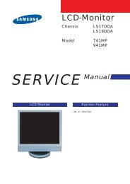
Figure 4-2 Foam bars<br />
The foam bars (order code 3122 785 90580 for two pieces) can<br />
be used for all types and sizes of Flat <strong>TV</strong>s. See figure “Foam<br />
bars” for details. Sets with a display of 42” and larger, require<br />
four foam bars [1]. Ensure that the foam bars are always<br />
supporting the cabinet and never only the display.<br />
Caution: Failure to follow these guidelines can seriously<br />
damage the display!<br />
By laying the <strong>TV</strong> face down on the (ESD protective) foam bars,<br />
a stable situation is created to perform measurements and<br />
alignments. By placing a mirror under the <strong>TV</strong>, you can monitor<br />
the screen.<br />
4.3.2 Speaker Cover<br />
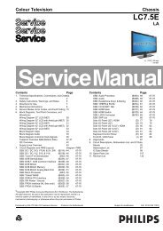
Figure 4-4 Rear cover removal<br />
1. Remove T10 Parker screws [1].<br />
2. Twist [2] and lift the speaker cover as shown.<br />
3. Now you have access to the speakers, Side I/O panel, IR/<br />
LED panel.<br />
4.2.2 Aluminium Stands<br />
1<br />
1<br />
1 1<br />
1<br />
2<br />
1 1 1<br />
1<br />
2<br />
1<br />
1<br />
H_16960_009.eps<br />
030407<br />
E_06532_019.eps<br />
170504<br />
Figure 4-5 Speaker cover removal<br />
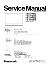
Figure 4-3 Aluminium stands (drawing of MkI)<br />
The new MkII aluminium stands (not on drawing) with order<br />
code 3122 785 90690, can also be used to do measurements,<br />
alignments, and duration tests. The stands can be<br />
(dis)mounted quick and easy by means of sliding them in/out<br />
the "mushrooms" (not valid for all models!). The new stands are<br />
backwards compatible with the earlier models.<br />
Important: For (older) F<strong>TV</strong> sets without these "mushrooms", it<br />
is obligatory to use the provided screws, otherwise it is possible<br />
to damage the monitor inside!