Create successful ePaper yourself
Turn your PDF publications into a flip-book with our unique Google optimized e-Paper software.
Circuit Descriptions, Abbreviation List, and IC Data Sheets <strong>LC7.1E</strong> PA 9. EN 73<br />
9.7 Audio Processing<br />
Principle<br />
The audio decoding is done entirely via the Multistandard<br />
Sound Processor (MSP) 4450P (item 7411).<br />
This processor covers the processing of both analogue and<br />
(NICAM) digital input signals by processing the (analogue) IF<br />
signal-in to processed (analogue) AF-out (baseband audio). An<br />
internal 40 ms (stereo) audio delay line (LIP SYNC) is foreseen<br />
and therefore no external delay line is necessary.<br />
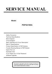
+V<br />
All internal clock signals are derived from an external<br />
18.432 MHz oscillator, which, in NICAM or I 2 S-mode, on its<br />
turn is locked to the corresponding source.<br />
-V<br />
G_16860_080.eps<br />
020207<br />
The following functionality is included:<br />
• Automatic Standard Detection (ASD) automatically detects<br />
the actual broadcasted <strong>TV</strong> standard<br />
• Automatic Sound Select (ASS) automatically switches<br />
(without any I 2 C-bus action) between mono/stereo/<br />
bilingual mode when the broadcast mode changes.<br />
9.7.1 Audio Application<br />
ANALOGUE<br />
FRONT END<br />
DVB / MOJO<br />
(if present)<br />
SCART 1 IN<br />
SCART 2 IN<br />
COMP IN<br />
SIDE IN<br />
HDMI IN<br />
HDMI<br />
IC<br />
2nd SIF<br />
I 2 S1<br />
AUDIO<br />
DAC<br />
SC1-IN<br />
SC2-IN<br />
SC3-IN<br />
SC4-IN<br />
SC5-IN<br />
MSP 4450P<br />
ANA_IN1+<br />
I 2 S_DA_IN1<br />
I2 S_WS<br />
I 2 S_CL<br />
DACM<br />
DACA<br />
CLASS D<br />
AMPLIFIER<br />
HP AMPLIFIER<br />
LOUDSPEAKER<br />
SC1-OUT<br />
SCART 1 OUT<br />
SC2-OUT SCART 2 OUT<br />
G_16860_055.eps<br />
090307<br />
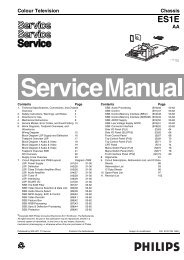
Figure 9-8 Block diagram audio processing - EU application<br />
In EU applications, the MSP features:<br />
• Sound IF input for signals coming from the analogue frontend<br />
• Three I 2 S-inputs for signals (“DATA”, “CLK” and “WS”)<br />
coming from the MOJO in case of digital reception<br />
• Five analogue inputs: for EXT1 to EXT4 and HDMI<br />
• Loudspeaker output path<br />
• Headphone output path<br />
• SCART-1 output path (RF)<br />
• SCART-2 output path (WYSIWYG = monitor).<br />
Digital audio signals coming from HDMI sources are fed to a<br />
digital-to-analogue converter and then fed to the MSP.<br />
In case of reception of digital <strong>TV</strong> signals, digital audio signals<br />
coming from the MOJO are directly fed to the MSP via the<br />
I2S_DA_IN1, I2S_WS1 and I2S_CL1 lines. This ensures a<br />
“true digital path”.<br />
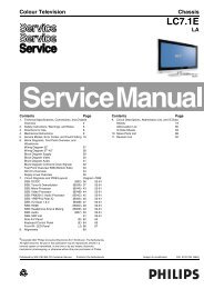
Figure 9-9 Principle Class-D Amplifier<br />
The Class D amplifier works by varying the duty cycle of a<br />
Pulse Width Modulated (PWM) signal.<br />
By comparing the input voltage to a triangle wave, the amplifier<br />
increases duty cycle to increase output voltage, and decreases<br />
duty cycle to decrease output voltage.<br />
The output transistors of a Class D amplifier switch from 'full off'<br />
to 'full on' (saturated) and then back again, spending very little<br />
time in the linear region in between. Therefore, very little power<br />
is lost to heat. If the transistors have a low 'on' resistance<br />
(RDS(ON)), little voltage is dropped across them, further<br />
reducing losses.<br />
A Low Pass Filter at the output passes only the average of the<br />
output wave, which is an amplified version of the input signal.<br />
In order to keep the distortion low, negative feedback is<br />
applied.<br />
The advantage of Class D is increased efficiency (= less heat<br />
dissipation). Class D amplifiers can drive the same output<br />
power as a Class AB amplifier using less supply current.<br />
The disadvantage is the large output filter. The main reason<br />
for this filter is that the switching waveform results in maximum<br />
current flow. This causes more loss in the load, which causes<br />
lower efficiency. An LC filter with a cut-off frequency less than<br />
the Class D switching frequency, allows the switching current<br />
to flow through the filter instead of the load, thus reducing the<br />
overall loss and increasing the efficiency.<br />
DC-protection<br />
A DC-detection circuit is foreseen to protect the speakers. It is<br />
built around three transistors (items 7A05 to 7A07) and<br />
generates a protection signal (DC_PROT) to the<br />
microprocessor in case of a DC failure in the Class D<br />
amplifiers.<br />
The microprocessor (item 7311) controls the audio part with the<br />
following control lines:<br />
• MUTEn: used to mute the Class D amplifiers<br />
• ANTI_PLOP: used to detect any DC failure in the Class D<br />
amplifiers<br />
• DC_PROT: used to detect any DC failure in the Class D<br />
amplifiers.<br />
9.7.2 Audio Amplifier<br />
The audio amplifier is an integrated class-D amplifier<br />
(TDA8932T, item 7A01). It combines a good performance with<br />
a high efficiency, resulting in a big reduction in heat generation.