
You also want an ePaper? Increase the reach of your titles
YUMPU automatically turns print PDFs into web optimized ePapers that Google loves.
ANUAL<br />
New Version<br />
850 V<br />
User Manual for<br />
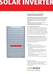
<strong>Sunways</strong> Solar Inverters NT 6000, NT 5000,<br />
NT 4000 and NT 2600<br />
200
OLAR<br />
NVERTERS<br />
User Manual for <strong>Sunways</strong><br />
Solar Inverters NT 6000, NT 5000, NT 4000<br />
and NT 2600
List of Contents<br />
1.0 General information<br />
1.1 Safety information<br />
93<br />
94<br />
General safety information<br />
Opening the unit<br />
1.2 <strong>Sunways</strong> Solar Inverters NT<br />
6000, NT 5000, NT 4000 and<br />
NT 2600<br />
95<br />
96<br />
97<br />
98<br />
Scope of supply<br />
Inspecting the delivery<br />
Integration into the PV system<br />
Design of the PV generator<br />
Standard components of a PV system<br />
Protection concept<br />
EN<br />
2.0 Information on installation<br />
2.1 Safety information<br />
2.2 Basic configuration<br />
2.3 Installation<br />
100<br />
101<br />
102<br />
103<br />
105<br />
106<br />
107<br />
Electrical safety<br />
Mechanical safety<br />
Information on cleaning<br />
Fixed voltage setting<br />
Country selection<br />
Requirements on the place of installation<br />
Electrical connection and cable entry<br />
Grid connection<br />
89
109<br />
111<br />
112<br />
114<br />
116<br />
PV generator connection<br />
Important Information<br />
Communication connections<br />
Connection of the alarm relay<br />
Connecting the sensors<br />
2.4 Commissioning<br />
118<br />
120<br />
Switching the <strong>solar</strong> inverter on and off<br />
Configurations<br />
3.0 Information on operation<br />
3.1 Monitoring and diagnosis<br />
125<br />
126<br />
Display<br />
Data memory<br />
3.2 <strong>Sunways</strong> NT Monitor software<br />
127<br />
128<br />
129<br />
134<br />
136<br />
137<br />
General information<br />
Initialising the remote modem<br />
Connection and circuitry options<br />
Configuring the interface cables<br />
Data acquisition<br />
Operation<br />
3.3 Fault indications<br />
139<br />
Fault indications<br />
3.4 Fault diagnosis<br />
143<br />
Fault display, causes and remedies<br />
90
3.5 Warranty terms and conditions<br />
150<br />
Warranty terms and conditions<br />
4.0 Appendix<br />
4.1 Subject and abbreviation index<br />
153<br />
Designation and description<br />
4.2 Function and information index<br />
155<br />
158<br />
160<br />
164<br />
166<br />
170<br />
Functional principle and explanations<br />
Block diagram of the Solar Inverter in<br />
the PV system<br />
Technical data<br />
Tyco Solarlok connectors<br />
Conformity and safety declarations<br />
General exclusion of liability<br />
Rights<br />
Registered trademarks<br />
EN<br />
91
1.0 General information<br />
92
1.1 Safety information<br />
General safety information<br />
The User Manual contains safety hints.<br />
These are identified by a triangle with an<br />
exclamation mark.<br />
!<br />
All safety hints contained in this section<br />
and throughout the User Manual must<br />
be complied with at all times to guarantee<br />
the user's safety. The described product<br />
must not be operated if any mechanical<br />
or electrical components are defective.<br />
Before commissioning the system, we<br />
strongly advise you to carefully read and<br />
heed the instructions! Non-compliance<br />
can have serious consequences, for example<br />
damage to the unit or other property<br />
or physical injuries with possible loss of<br />
life.<br />
EN<br />
The <strong>solar</strong> inverter must be installed by a<br />
trained, qualified electrician. The electrician<br />
must be approved by the competent<br />
electricity board (EB). The relevant tasks<br />
to be carried out are identified by an additional<br />
adjacent symbol in the respective<br />
chapter headings.<br />
93
!<br />
Opening the unit<br />
Before opening the cabinet, the unit must<br />
always be disconnected from the grid and<br />
from the PV generator.<br />
The unit continues to conduct a hazardous<br />
voltage internally and at the connection<br />
sockets for ca. five minutes after disconnecting<br />
from the PV generator. The energy<br />
storage capacitors are only fully discharged<br />
after this period.<br />
After disconnecting the unit from the grid<br />
and from the PV generator, you must wait<br />
at least five minutes before opening the<br />
unit.<br />
94
1.2 <strong>Sunways</strong> Solar Inverters NT 6000,<br />
NT 5000, NT 4000 and NT 2600<br />
Scope of supply<br />
· <strong>Sunways</strong> Solar Inverter in the NT series<br />
· Installation frame<br />
· Manual, setup, warranty card, CD-Rom<br />
with software<br />
· 2 pairs of Tyco Solarlok connectors<br />
Inspecting the delivery<br />
The condition of our products is checked<br />
prior to delivery. Although our products<br />
are carefully packed in recyclable packing,<br />
transportation damages can still occur.<br />
These are generally the transport company's<br />
responsibility.<br />
Please inspect the delivered <strong>solar</strong> inverter<br />
thoroughly!<br />
EN<br />
If you discover any damage to the packing<br />
or the <strong>solar</strong> inverter, please inform the<br />
transport company immediately. Your<br />
specialist dealer will be glad to assist you<br />
if required. Any damages must always be<br />
reported to the transport company in writing<br />
seven days after receipt of the goods<br />
at the latest.<br />
95
Integration of the <strong>solar</strong> inverter into the<br />
PV system<br />
Design of the PV generator<br />
The technical data of the selected PV<br />
generator must be within the specification<br />
of the <strong>solar</strong> inverter (see Technical Data).<br />
Incorrect dimensioning can cause losses in<br />
yield and destruction of the unit. The<br />
<strong>Sunways</strong> NT Sundim design program for<br />
the PV generator may be helpful. <strong>Sunways</strong><br />
NT Sundim is available on the enclosed<br />
CD or from our website, www.sunways.de.<br />
· Check your PV generator for soiling ca.<br />
every three years. This occurs particularly<br />
at the lower edge of the modules and<br />
forms a film, which even heavy rain cannot<br />
wash away. Decreases in yield can be<br />
prevented by cleaning with a wet cloth<br />
or a brush.<br />
· Avoid shading of individual modules or<br />
<strong>solar</strong> cells in your system. This can result<br />
in heavy losses in yield.<br />
Please take account of the following points<br />
before planning your system:<br />
· Pay attention to the skyward alignment<br />
of the modules. You will obtain maximum<br />
yield in Central Europe with a<br />
module inclination of 30° to the horizontal<br />
and a direct southerly alignment<br />
of the generator field.<br />
· The output of the cells decreases as the<br />
module temperature increases. Install<br />
your PV generator with adequate rear<br />
ventilation.<br />
96
Standard components of a PV system<br />
Depending on the recommendations<br />
of your electrician, your PV system will<br />
consist of the following components:<br />
Standard components of the PV system<br />
PV<br />
PV (1)<br />
INVERTER<br />
(3)<br />
(4)<br />
(1) PV generator switch<br />
(2) Irradiation sensor with<br />
integrated temperature<br />
sensor<br />
(3) Mains fuse<br />
(4) Energy meter<br />
(2)<br />
PC<br />
GRID<br />
PV generator switch:<br />
Designed as DC load break cut-out to cut<br />
off the PV generator from the <strong>solar</strong> inverter.<br />
Dimensioning: min. 900 V, ≥ 16 A<br />
Grid connection:<br />
3-phase (Feed-in: 1-phase; grid monitoring:<br />
3-phase)<br />
97
Protection concept<br />
The following parameters are monitored<br />
continuously and in parallel by the microcontroller<br />
and displayed on the screen:<br />
· DC overvoltage (Fault 3)<br />
· Frequency error (Fault 4)<br />
· Overheating (Fault 5)<br />
· Grid undervoltage, 1-phase (Fault 6)<br />
· Grid overvoltage, 1-phase (Fault 7)<br />
· Grid undervoltage, 3-phase (Fault 8)<br />
· AFI error (Fault 9)<br />
· Insulation error (Fault 10)<br />
· DC feed (Fault 11)<br />
· Isolated operation (Fault 12)<br />
· Grid overvoltage, 3-phase (Fault 13)<br />
· Surge error (Fault 14)<br />
· Grid voltage 10-minute average value<br />
> 10 % U NOM (Fault 15)<br />
In the event of a fault, the conversion is<br />
blocked immediately and the grid relay is<br />
isolated. An alarm relay with floating<br />
output is activated (not for Fault 6).<br />
In addition, the following protective<br />
devices are provided on both grid and<br />
PV generator side:<br />
· Grid-side varistors<br />
Protect the power semiconductors from<br />
high-energy, time-limited voltage spikes<br />
on the grid and provide for a reduction<br />
of energy in the throttle in the event of<br />
grid disconnection.<br />
· Generator-side varistors<br />
Thermally monitored varistors provide<br />
protection against atmospheric overvoltages<br />
(e.g. due to remote strikes during<br />
storms).<br />
98
2.0 Information on installation<br />
99<br />
200
2.1 Safety information<br />
!<br />
<br />
Electrical safety<br />
Before opening the cabinet, the <strong>solar</strong><br />
inverter must be disconnected from the<br />
grid and from the PV generator.<br />
The <strong>solar</strong> inverter conducts a hazardous<br />
voltage internally and at the connectors of<br />
the PV generator for approx. five minutes<br />
after isolation from the PV generator and<br />
the grid. The energy storage capacitors are<br />
only fully discharged after this period.<br />
After disconnecting the <strong>solar</strong> inverter from<br />
the grid and PV generator, you must wait<br />
at least five minutes before opening the<br />
<strong>solar</strong> inverter.<br />
Mechanical safety<br />
During installation, make sure that the<br />
cables or connection lines fitted to the<br />
<strong>solar</strong> inverter are securely laid and that<br />
suitable mechanical cable supports<br />
(cable ducts etc.) are used.<br />
100
!<br />
Information on cleaning<br />
Before cleaning, disconnect the system<br />
from the power grid by opening the grid<br />
breaker (main fuse) and open the DC<br />
switch on the PV generator, in order to<br />
exclude the danger of electric shocks.<br />
Use a soft, dry cloth to clean the system.<br />
Never use corrosive, solvent-containing<br />
or abrasive cleaners or polishes.<br />
EN<br />
101
2.2 Basic configuration<br />
Fixed voltage setting<br />
Your <strong>Sunways</strong> <strong>solar</strong> inverter has a precise<br />
MPP control. The control operates in fixed<br />
voltage mode beneath a feed-in capacity<br />
of 200 watts. This prevents unnecessary<br />
MPP search behaviour. In order to minimise<br />
the adaptive losses in fixed voltage<br />
mode, the <strong>solar</strong> inverter has the facility to<br />
set the fixed voltage level. The optimal<br />
fixed voltage level is dependent on your<br />
PV generator model.<br />
Switch position<br />
«410 V»<br />
Switch position<br />
«530 V»<br />
Fixed voltage level<br />
depending on noload<br />
voltage<br />
No-load voltage PV<br />
generator at 25°C<br />
(Fig.) Sliding switch to set the fixed<br />
voltage level<br />
410 V<br />
530 V<br />
≤ 630 V<br />
> 630 V<br />
The fixed voltage can be set with the S100<br />
slide switch on the control board. At the<br />
factory, the switch is set on the right in<br />
status «410 V». In order to set a fixed voltage<br />
of 530 V, slide the switch to the left<br />
into the «530 V» position.<br />
102
Country selection<br />
Please note that a different device configuration<br />
is required to operate <strong>Sunways</strong><br />
Solar Inverters in different countries. You<br />
can make the relevant setting with DIP<br />
switch S300 beneath the display panel.<br />
(Fig.) DIP switch S300 for country selection<br />
EN<br />
Country<br />
switch position<br />
modification<br />
Germany<br />
Spain<br />
· Disconnect interval after power failure<br />
3 minutes<br />
· 1-phase grid monitoring<br />
103
2.3 Installation<br />
The <strong>solar</strong> inverter must be installed by a trained, qualified electrician. A special tool is<br />
necessary for installation. Please read this chapter very carefully.<br />
(Fig.) Minimum<br />
distances that<br />
must be kept clear<br />
around the <strong>solar</strong><br />
inverter<br />
Warm<br />
air<br />
150 mm<br />
Cool air<br />
➟<br />
➟<br />
300 mm 300 mm<br />
➟<br />
➟<br />
150 mm<br />
104
Requirements on the place of installation<br />
· Mechanical bearing capacity<br />
During installation please bear in mind<br />
that the <strong>solar</strong> inverter weighs 26 kg. The<br />
installation base must be firm and capable<br />
of continuously bearing the weight.<br />
· Thermal interaction<br />
The installation base must consist of<br />
flame-retardant material (e.g. no wood or<br />
plastic in the base; concrete and brickwork<br />
are suitable), as the heat sink emits temperatures<br />
up to max. 85°C.<br />
A minimum distance of 300 mm must be<br />
maintained above and below the cabinet,<br />
and 150 mm on right and left from other<br />
units, cabinets, ceilings, cable ducts etc..<br />
The <strong>solar</strong> inverter must be installed vertically,<br />
so as not to hinder adequate free<br />
convection.<br />
If installing the <strong>solar</strong> inverter in a switch<br />
box, ensure adequate heat dissipation.<br />
The ambient temperature must not fall<br />
below or exceed –25°C or +40°C.<br />
The <strong>solar</strong> inverter should not be exposed to<br />
direct <strong>solar</strong> irradiation, so as to protect it<br />
from unnecessary external heating.<br />
· Protection from damp and foreign bodies<br />
The IP54 high protection class permits installation<br />
both inside and in roofed outdoor<br />
areas, but the <strong>solar</strong> inverter must not be<br />
exposed to direct rain.<br />
Make sure that the <strong>solar</strong> inverter cannot be<br />
exposed to foreign bodies (deposits of dust<br />
and dirt). In order to avoid losses in yield,<br />
the unit should be regularly freed from dust<br />
deposits.<br />
EN<br />
Several <strong>solar</strong> <strong>inverters</strong> must not be installed<br />
on top of each other, so as to prevent<br />
reciprocal heating.<br />
105
Electrical connection and cable entry<br />
!<br />
For installation, please observe the<br />
instructions in the «Setup» leaflet!<br />
If the <strong>solar</strong> inverter is fixed to the installation<br />
frame, the electrical connection can<br />
be led through. The unit may only be opened<br />
by a qualified electrician. The cabinet<br />
cover must first be released and removed.<br />
The SUB-D connector for the RS 232 connection<br />
is located on the bottom, as well<br />
as inlets for cables:<br />
Irradiation sensor with<br />
DC– DC–<br />
DC+ DC+<br />
integrated temperature<br />
sensor cable<br />
Alarm relay<br />
RS 485 RS 232<br />
AC wiring loom<br />
L1, N, L2, L3, PE<br />
(Fig.) Inlets on the unit underside<br />
106
Grid connection<br />
!<br />
The grid connection of the <strong>solar</strong> inverter<br />
must have 5 wires (L1, N, L2, L3, PE). Cable<br />
cross-sections of 5 x 4 mm 2 are recommended.<br />
The <strong>solar</strong> inverter is connected to the supply<br />
grid via the circuit board terminals inside<br />
the unit.<br />
We recommend a 3 x 25 A safety cutout<br />
for devices NT 6000, NT 5000 and NT 4000<br />
and a 3 x 16 A safety cutout for device<br />
NT 2600 as grid protection element in the<br />
grid feed-in direction. No consumption<br />
units must be connected to the feed line<br />
from the <strong>solar</strong> inverter to the automatic<br />
cut-out. The <strong>solar</strong> inverter only feeds in<br />
via terminal L1. Please always observe the<br />
connection configuration. Incorrect configuration<br />
can result in destruction of the<br />
unit.<br />
EN<br />
Three-phase grid connection distributed over three units<br />
L1 N L2 L3 PE L1 N L2 L3 PE L1 N L2 L3 PE<br />
L1<br />
L2<br />
L3<br />
N<br />
PE<br />
107
If several <strong>solar</strong> <strong>inverters</strong> are operated in<br />
parallel, the feed-in phase L1 of the unit<br />
must be evenly distributed over grid phases<br />
L1, L2 and L3 (see Fig. page 107).<br />
You must use adequately dimensioned<br />
cable cross-sections in order to avoid a<br />
considerable increase in the grid impedance<br />
between the domestic distribution<br />
and the <strong>solar</strong> inverter. The terminal range<br />
of the AC terminals is 0.5 to 6 mm2 for<br />
rigid cables and 0.5 to 10 mm2 for flexible<br />
cables. With a high grid impedance,<br />
i.e. with a long line or too small a crosssection,<br />
the voltage increases at the grid<br />
terminal during feed-in.<br />
· Check that there is no voltage before<br />
introducing the supply main into the<br />
unit.<br />
· Lead the 5-core AC cable (outer diameter<br />
9 – 17 mm) through the M32<br />
threaded cable gland.<br />
· Connect cables L1, N, L2, L3 and PE to<br />
the relevant circuit board terminal with<br />
the help of a slot-head screwdriver<br />
If the terminal voltage exceeds the permissible<br />
value, the <strong>solar</strong> inverter is discon-nected<br />
from the grid. In the case of<br />
poorly designed electric grids and high<br />
PV output, this can also result in repeated<br />
switching off and on of individual <strong>solar</strong><br />
<strong>inverters</strong>.<br />
Carefully perform the following steps:<br />
(Fig.) Circuit board terminal for fixing<br />
the grid cable<br />
· Tighten the M32 screw connection, so<br />
that the cable cannot exert any mechanical<br />
force on the circuit board terminal.<br />
108
PV generator connection<br />
!<br />
· Preparation<br />
Execute the DC cabling according to your<br />
electrician's system dimensioning. Check<br />
each PV string for correct functioning<br />
by performing a no-load voltage current<br />
and short-circuit current measurement.<br />
Check the rating plate on the <strong>solar</strong> inverter<br />
to ensure that the inverter is approved<br />
for the maximum PV generator voltage.<br />
EN<br />
To achieve the necessary protection<br />
against hazardous contact voltage during<br />
the installation of PV systems, the positive<br />
and negative conductors must be kept<br />
separate from the ground potential (PE).<br />
Contactable, conductive parts of the PV<br />
generator (e.g. metal frame, supporting<br />
structure etc.) must be earthed (connected<br />
to PE).<br />
Check that the generator is free from<br />
ground faults.<br />
Make the electrical connection to the<br />
<strong>solar</strong> inverter.<br />
109
· Connection<br />
The PV generator is connected via the<br />
externally accessible, shock-proof Tyco<br />
Solarlok connectors, which are enclosed<br />
with the delivery. The Tyco Solarlok connectors<br />
are designed for a cable crosssection<br />
of 4 mm 2 and must be crimped<br />
(see chapter 4.2 «Tyco Solarlok connection»).<br />
Connect the two right DC female connectors<br />
with «+», the two left DC female<br />
connectors with «–» of the PV generator.<br />
Always ensure the correct polarity!<br />
(Fig.) PV generator connection via Tyco<br />
Solarlok connector<br />
110
Important information<br />
!<br />
· The direct PV generator voltage is available<br />
internally after connecting the PV<br />
generator to the <strong>solar</strong> inverter via the<br />
DC connectors and switching on the PV<br />
generator switch!<br />
· Please note that the input capacitors are<br />
still charged even after switching off the<br />
PV generator switch or removing the PV<br />
generator plug connection!<br />
· After disconnecting the AC and DC side,<br />
the <strong>solar</strong> inverter still conducts voltage<br />
for up to ca. five minutes!<br />
· Therefore, wait for at least five minutes<br />
until the internal voltage has dissipated.<br />
Then you can work on the terminals!<br />
Note chapter 2.1 «Safety information»!<br />
· The DC voltage can be up to 850 V. The<br />
unit may only be opened by a qualified<br />
electrician!<br />
· Always disconnect the PV generator side<br />
first by opening the PV generator switch,<br />
and then the grid connection by isolating<br />
the relevant mains fuse!<br />
· If you do not have a PV generator switch<br />
in your PV system, you must disconnect<br />
the grid connection first of all by isolating<br />
the relevant mains fuse. However,<br />
an error will be entered in the error<br />
memory of the <strong>solar</strong> inverter!<br />
· Disconnection of the PV generator by<br />
removing the Tyco Solarlok DC connectors<br />
must never be performed under<br />
load. In the event of non-compliance,<br />
the connectors could be damaged by a<br />
strong electric arc. In this case, the rele<br />
vant connectors must be replaced!<br />
EN<br />
111
Communication connections<br />
!<br />
Via the communication connections (interfaces),<br />
operating data can be retrieved<br />
from the data memory with an external<br />
computer and specific operating settings<br />
made. Several communication interfaces<br />
are available: RS 232 and RS 485.<br />
The standard communication interface is<br />
the RS 232 interface, which is installed in<br />
all current PCs and notebooks. This interface<br />
allows you to establish contact with<br />
your PC immediately, using a connecting<br />
cable. The use of more than one <strong>solar</strong><br />
inverter or cable lengths of more than<br />
25 m requires the use of the RS 485<br />
interface.<br />
(Fig.) SUB-D connector for RS 232 connection<br />
Attention: RS 485+ and RS 485- are duplicated.<br />
This means that the cable entry and<br />
exit are additionally clamped.<br />
The RS 232 interface is connected directly<br />
to the outside of the housing via a SUB-D<br />
connector. The RS 485 interface is connected<br />
via the circuit board terminals and the<br />
corresponding M12 threaded cable glands<br />
in the housing.<br />
(Fig.) Connection block for RS 485<br />
112
· Connection RS 485<br />
Remove the cover of the <strong>solar</strong> inverter<br />
before connecting an interface cable.<br />
Note chapter 2.1 «Safety information»!<br />
The necessary cable terminal block (X400)<br />
with the RS 485+, RS 485+, RS 485- and RS<br />
485- connections is located in the lower<br />
section of the board (see fig. page 112).<br />
Note the following terminal configuration:<br />
Seal the unrequired cable glands by placing<br />
a spare piece of cable in the gland<br />
hole and tightening with the screw clamp.<br />
Please note chapter 3.2 «<strong>Sunways</strong> NT<br />
Monitor software».<br />
· RS 232 connection<br />
The RS 232 interface is externally accessible<br />
via the SUB-D connector.<br />
EN<br />
RS 485: RS 485+, RS 485+, RS 485-, RS 485-<br />
Use a small screwdriver. Press the orange<br />
terminal. The terminal will open.<br />
Please note chapter 3.2 «<strong>Sunways</strong> NT<br />
Monitor software».<br />
Insert the cable stripped to a minimum of<br />
11 mm into the respective terminal hole.<br />
Release the screwdriver. The cable is fixed<br />
in the connection.<br />
Once again, check that the cable connection<br />
is firmly located.<br />
113
Connection of the alarm relay<br />
!<br />
<strong>Sunways</strong> Solar Inverters are equipped as<br />
standard with an alarm relay with floating<br />
output. The relay is designed as a make<br />
contact and is activated in the case of all<br />
faults reported by the unit (not for Fault 6).<br />
This guarantees quick and reliable indication<br />
of possible faults in the PV system.<br />
In the case of PV systems with several<br />
<strong>solar</strong> <strong>inverters</strong>,the individual relays can<br />
be parallel-connected and connected via<br />
a joint signal light.<br />
· Connection<br />
Remove the housing of the <strong>solar</strong> inverter<br />
before connecting the status signal relay.<br />
Note chapter 2.1 «Safety information»!<br />
The necessary terminal block with the connections<br />
«S-» and «S+» is located on the<br />
board at the bottom right (X402). Note the<br />
following terminal configuration:<br />
Parallel connection of the alarm relays of<br />
several <strong>solar</strong> <strong>inverters</strong><br />
Terminal configuration for the alarm relay<br />
INVERTER<br />
(1)<br />
INVERTER<br />
(2)<br />
INVERTER<br />
(n)<br />
S– S – S+ S +<br />
SIGNAL LIGHT<br />
L1 N
(Fig.) Connection of the alarm relay<br />
Important information: The alarm relay is<br />
designed for 230 V / 2 A. Higher outputs /<br />
voltages can result in destruction of the<br />
relay. The connected signal input must<br />
have separate fuse protection!<br />
!<br />
The terminals are designed for a cable<br />
cross-section of 0.2 mm 2 to 1.5 mm 2 .<br />
Please also take account of the power<br />
consumption of the connected signal<br />
input when dimensioning the cross-section!<br />
EN<br />
Using a small screwdriver, press the orange<br />
terminal. The terminal will open. Insert the<br />
minimum 11 mm stripped cable into the<br />
respective terminal hole. Loosen the screwdriver.<br />
The cable is fixed in the connection.<br />
Once again, check that the cable connection<br />
is firmly located.<br />
115
Connecting the sensors<br />
!<br />
· Optional irradiation sensor<br />
The optional addition of an irradiation<br />
sensor (type Si-01TC-T from Ing.-Büro<br />
Mencke & Tegtmeyer ) with integrated<br />
PT-100 temperature sensor for temperature<br />
measurement enables recording of<br />
the irradiation data and the corresponding<br />
module temperature in the cycle<br />
of the internal data memory.<br />
Before you connect an irradiation sensor,<br />
you must remove the cover of the <strong>solar</strong><br />
inverter. Please note that the inputs and<br />
outputs are not short-circuit resistant.<br />
Note chapter 2.1 «Safety information»!<br />
The optional irradiation sensor with temperature<br />
probe is connected to cable<br />
terminal block X401 in the lower section<br />
of the board.<br />
This additional measuring unit helps with<br />
analysis of the system. On the basis of the<br />
values, possible errors in the PV generator,<br />
such as e.g. shading or failure of <strong>solar</strong> cells,<br />
can be detected.<br />
For demonstration purposes, the irradiation<br />
sensor and the corresponding data<br />
can be used to show how a PV system<br />
functions. In conjunction with the<br />
<strong>Sunways</strong> NT Monitor visualisation software,<br />
the stored data can be displayed.<br />
(Fig.) Connection block for the irradiation<br />
sensor<br />
116
Configuration of the cable terminal block:<br />
Temperature sensor<br />
measuring signal: Temp<br />
Solar radiation<br />
measuring signal: Solar<br />
Positive supply, 5V: V+<br />
Supply, GND: V –<br />
Using a small screwdriver, press the orange<br />
terminal. The terminal will open.<br />
EN<br />
Insert the cable stripped to a minimum of<br />
11 mm into the respective terminal hole.<br />
Loosen the screwdriver. The cable is fixed<br />
in the connection.<br />
Once again, check that the cable connection<br />
is firmly located.<br />
117
2.4 Commissioning<br />
Switching the <strong>solar</strong> inverter on and off<br />
Connect the <strong>solar</strong> inverter internally via<br />
the ground cable (yellow-green) to the<br />
cabinet cover. See also Setup, step 7.<br />
Put the cabinet cover on.<br />
· Switching on<br />
When the <strong>solar</strong> inverter is mechanically<br />
installed and connected to the electrical<br />
cables, the unit can be commissioned as<br />
follows:<br />
Screw it down tightly with the four<br />
screws on the front.<br />
Switch the grid connection on through<br />
the external safety cutouts.<br />
Do not place any objects (e.g. this manual)<br />
on the cabinet of the <strong>solar</strong>inverter.<br />
Free ventilation behind the <strong>solar</strong> inverter<br />
must be able to take place unimpeded.<br />
If the unit is mounted outdoors, please<br />
ensure proper sealing of the threaded<br />
cable glands and precise positioning of<br />
the housing cover as well as the protective<br />
cover of the SUB-D connector, if this<br />
connection is not configured.<br />
Switch the PV generator voltage on by<br />
closing the PV generator switch. The <strong>solar</strong><br />
inverter will start up with adequate<br />
PV power. If the PV input voltage is high<br />
enough, the <strong>solar</strong> inverter will begin operation<br />
and feed the <strong>solar</strong> energy into the<br />
electrical grid. You can see the operation<br />
on the display. The current feed-in power<br />
is shown here.<br />
The <strong>solar</strong> inverter is supplied by the grid.<br />
With adequate PV output, the <strong>solar</strong> inverter<br />
switches on automatically. Appropriate<br />
switch-on and switch-off thresholds are<br />
fixed for this purpose.<br />
118
· Switching off<br />
Disconnect the PV generator side first by<br />
opening the PV generator switch, and<br />
then the grid connection by isolating the<br />
relevant mains fuse.<br />
If your PV system does not have a PV<br />
generator switch, you must disconnect<br />
the grid connection first of all by isolating<br />
the relevant mains fuse. When you do<br />
this, an error will be entered in the error<br />
memory of the <strong>solar</strong> inverter.<br />
If the <strong>solar</strong> inverter is to be completely<br />
disconnected (e.g. removal) from the PV<br />
system, reconfigured or extended, the<br />
cabinet cover must be removed. Note<br />
chapter 2.1 «Safety information»!<br />
!<br />
Open the main switch for the PV DC<br />
voltage and the mains fuse as described<br />
above. After a waiting period of at least<br />
five minutes, the <strong>solar</strong> inverter will be<br />
voltage-free.<br />
Disconnection of the PV generator by<br />
removing the Tyco Solarlok connectors<br />
must never be performed under load.<br />
In the event of non-compliance, the connectors<br />
could be damaged by a strong<br />
electric arc. In this case, the relevant connectors<br />
must be replaced!<br />
Remove the cabinet cover.<br />
EN<br />
Check that the grid connection terminals<br />
are voltage-free.<br />
119
Configurations<br />
The <strong>solar</strong> inverter is basically configured<br />
with the <strong>Sunways</strong> NT Monitor program,<br />
using a laptop or PC (see enclosed CD).<br />
Please read the chapter 3.1 «System<br />
Monitoring and Diagnosis» and 3.2<br />
«<strong>Sunways</strong> NT Monitor».<br />
However, language setting, LCD contrast<br />
and total energy offset (only to be used<br />
in the event of replacement) must be<br />
configured directly on the unit. If you wish<br />
to configure the <strong>solar</strong> inverter without<br />
an external laptop or PC, or to change the<br />
language setting, please follow the<br />
instructions below:<br />
! <br />
Direct configuration of the <strong>solar</strong> inverter<br />
occurs in operation!<br />
Please note that the unit is under DC<br />
voltage for configurations via the keys.<br />
Danger to life!<br />
Please observe all essential regulations for<br />
«Working under voltage»!<br />
120
This is the only exception for which work<br />
may be performed on the open unit under<br />
voltage!<br />
Remove the cabinet cover to carry out the<br />
configuration.<br />
The following settings can be performed<br />
using the illustrated keys:<br />
· Address of the <strong>solar</strong> inverter: address<br />
«1» is stored in the memory at the<br />
factory. In the case of several <strong>solar</strong> <strong>inverters</strong>,<br />
consecutive numbering must be set.<br />
For three <strong>solar</strong> <strong>inverters</strong> e.g. the addresses<br />
«1», «2» and «3».<br />
· Date<br />
· Time<br />
· Language (German, English, French,<br />
Spanish, Italian)<br />
EN<br />
A<br />
B<br />
C<br />
D<br />
(Fig.) The setting keys are located beneath the display<br />
121
Use insulating material to press the keys<br />
(e.g. a plastic rod). Avoid direct contact<br />
with the printed circuit board, so that the<br />
electronics cannot be damaged by electrostatic<br />
charging. Starting from the current<br />
display on the screen, you can reach the<br />
next menu level with the D-key. The illustrated<br />
structure facilitates settings on the<br />
menu levels. Then save your settings by<br />
pressing the C-key.<br />
Structure and menu levels for configuration<br />
PERFORMANCE<br />
AND<br />
OPERATING DATA<br />
START<br />
▲<br />
D<br />
C<br />
SOLAR INVERTER<br />
ADRESS<br />
A/B DATE A/B TIME A/B<br />
D D D D D D<br />
A ADRESS B A DAY<br />
1 ... 99<br />
B<br />
A<br />
HOURS<br />
B<br />
C<br />
C<br />
C<br />
A<br />
MONTH<br />
B<br />
A<br />
MINUTES<br />
B<br />
C<br />
C<br />
C<br />
A<br />
YEAR<br />
B<br />
A<br />
SECONDS<br />
B<br />
C<br />
SAVE<br />
122
LANGU<strong>AG</strong>E<br />
SOFTWARE<br />
A/B LCD CONTRAST A/B A/B<br />
VERSION<br />
TOTAL POWER<br />
OFFSET<br />
D D D D D D<br />
A<br />
ENGLISH/GERMAN/<br />
ITALIAN/FRENCH/<br />
SPANISH<br />
B<br />
A<br />
CONTRAST<br />
B<br />
A<br />
kWh<br />
C<br />
INCREMENT<br />
(100 OR 1)<br />
B<br />
123
3.0 Information on operation<br />
124
3.1 Monitoring and diagnosis<br />
Display<br />
The dot matrix LCD display is integrated<br />
into the cabinet of the <strong>solar</strong> inverter so<br />
that it is easily visible. The display consists<br />
of 16 characters and 2 lines. The top line 1<br />
shows the current feed-in power of the<br />
<strong>solar</strong> inverter. The bottom line 2 outputs<br />
operating data. The data can be displayed<br />
in the German, English, French, Spanish or<br />
Italian language.<br />
EN<br />
Line 1 Current fed-in power Power kW<br />
Line 2 AC voltage U-AC V<br />
DC voltage U-DC V<br />
Daily yield W-DAY Wh<br />
Total yield W-TOT kWh<br />
Irradiation * SOLAR W/m 2<br />
PV generator temperature * TEMP-PAN °C<br />
Time<br />
TIME<br />
* if the optional irradiation sensor with<br />
integrated temperature sensor is connected<br />
125
Data memory<br />
Your <strong>solar</strong> inverter is equipped with an<br />
internal data memory as standard. This<br />
data memory provides you with a detailed<br />
view of the mode of functioning and the<br />
relevant values of your <strong>solar</strong> power supply<br />
at all times. You can access these data<br />
with the help of the NT Monitor software<br />
described below. The following measured<br />
values can be determined:<br />
· DC voltage<br />
· AC voltage and AC current (power calculation)<br />
· Irradiation and module temperature<br />
(if a sensor is connected)<br />
· Time and date<br />
· Storage of accumulated daily work in<br />
Wh and of 40 daily values in the recirculating<br />
storage and successive overwriting<br />
of values<br />
· Storage of accumulated monthly work in<br />
kWh and of 13 monthly values in the<br />
recirculating storage, then overwriting<br />
of values<br />
· Storage of faults with max. ten values,<br />
then successive overwriting of values<br />
Please note that all displayed data are<br />
displayed with a nominal measuring accuracy<br />
of maximum 5 per cent. The energy<br />
counter of your EVU should be used as<br />
absolute reference for the fed-in energy.<br />
The following values are accumulated,<br />
stored and continuously overwritten:<br />
· 15 minute values for AC current, DC and<br />
AC voltages, irradiation and temperature<br />
· 500 times storage of 15-minute average<br />
values in the recirculating storage; storage<br />
depth: ten days on average, then<br />
overwriting of values<br />
126
3.2 <strong>Sunways</strong> NT Monitor software<br />
General information<br />
The <strong>Sunways</strong> NT Monitor visualisation software<br />
was developed for PV system monitoring<br />
and configuration of the <strong>solar</strong> inverter<br />
using PC. It is contained on the enclosed CD<br />
and can also be downloaded free of charge<br />
on the Internet from www.sunways.de.<br />
System prerequisites are:<br />
· Intel Pentium from 100 MHz or higher<br />
· Microsoft Windows 95/98/2000/NT<br />
· At least 6 MB free hard disk storage space<br />
· At least 16 MB main memory<br />
· VGA monitor with at least 800 x 600<br />
(120 dpi) resolution<br />
All measured values can be transferred<br />
to a PC and visualised with the <strong>Sunways</strong> NT<br />
Monitor software. Online, fault, minute,<br />
daily and monthly values are available.<br />
For connecting to your PC, <strong>Sunways</strong> <strong>solar</strong><br />
<strong>inverters</strong> in the NT series are equipped with<br />
the RS 232 and RS 485 interfaces as standard.<br />
In the case of larger distances between<br />
PV system and PC, the data can also<br />
be transferred via a modem. We recommend<br />
using two external analogue<br />
modems made by ACER. If other modems<br />
are used, the functional reliability cannot<br />
always be guaranteed.<br />
The modem (remote modem) installed<br />
in the <strong>solar</strong> inverter must be initialised<br />
prior to installation with the help of the<br />
<strong>Sunways</strong> NT Monitor software. Note the<br />
"Help" function in the program in this<br />
regard.<br />
The second modem (local modem) is<br />
connected to the RS 232 interface of your<br />
PC. This modem must not be initialised.<br />
Different interface cables are required,<br />
depending on the type of connection.<br />
These are included in the accessories.<br />
Up to 99 <strong>solar</strong> <strong>inverters</strong> can be monitored<br />
and read out by means of a connection<br />
via the RS 485 interface.<br />
If the data are read out via the RS 485<br />
interface and converted to RS 232 with<br />
an interface converter, we recommend<br />
the converter type «I-7520 Converter»<br />
127<br />
EN
from ICP-Deutschland, (available from your<br />
specialist dealer), which will guarantee<br />
reliable data transfer.<br />
· Attention! Do not initialise the local<br />
modem which is intended for use on<br />
the PC!<br />
The addresses of the <strong>solar</strong> inverter must<br />
be input with the <strong>Sunways</strong> NT Monitor<br />
software. Alternatively, see chapter 2.4<br />
«Commissioning, configurations».<br />
· The remote modem is now initialised<br />
so that it automatically accepts a connection<br />
after two rings and connects at<br />
9600 Baud.<br />
Initialising the remote modem<br />
If a remote modem is installed in the <strong>solar</strong><br />
inverter, it must be initialised using a PC<br />
and the <strong>Sunways</strong> NT Monitor software.<br />
· Connect the powered remote modem to<br />
the PC via the COM port. Use the interface<br />
cable provided with the modem for<br />
this purpose. Start the <strong>Sunways</strong> NT<br />
Monitor and set «Acer Modem» under<br />
the «Settings/Remote Modem» menu.<br />
· Click «Perform initialisation» and wait<br />
until the scroll bar has come to an end.<br />
The modem can now be switched off<br />
and connected to the <strong>solar</strong> inverter via<br />
the RS 232 interface.<br />
128
Connection and circuitry options<br />
(1) Individual PV system with maximum distance of 25 m between <strong>solar</strong> inverter an PC<br />
PV<br />
INVERTER<br />
(1)<br />
RS 232<br />
PC<br />
Connection to the PC via RS 232<br />
SUB-D connector<br />
An individual <strong>solar</strong> inverter can be connected<br />
directly to the PC via the external RS 232<br />
interface on the bottom of the device.<br />
Jumper JP400: open<br />
(1) An individual <strong>solar</strong> inverter can be<br />
read out using this connection, unless the<br />
distance from the PC exceeds a distance<br />
of 25 m. For this purpose, cable type 1 is<br />
connected with the <strong>solar</strong> inverter via the<br />
SUB-D connector and connected to a PC.<br />
Jumper JP400 must be in open position.<br />
129
(2) Individual PV system with modem for remote inquiry<br />
PV<br />
INVERTER<br />
(1)<br />
RS 232 MODEM MODEM<br />
RS 232<br />
PC<br />
Connection to modem via RS 232<br />
SUB-D connector<br />
When connecting an individual <strong>solar</strong> inverter,<br />
the remote modem is connected directly to an<br />
external interface converter (IC) RS 232 at the<br />
bottom of the <strong>solar</strong> inverter.<br />
Jumper JP400: open<br />
(2) For installation of the remote inquiry<br />
of an individual <strong>solar</strong> inverter, the RS 232<br />
signal can be conducted directly from the<br />
<strong>solar</strong> inverter to the remote modem via<br />
the SUB-D connector. Cable type 2 is used<br />
for this purpose. A cable length of 25 m<br />
should not be exceeded for the RS 232<br />
connection between <strong>solar</strong> inverter and<br />
modem. Jumper JP400 must be in open<br />
position.<br />
130
(3) PV system for 2 to 99 <strong>solar</strong> <strong>inverters</strong> with interface converter (IC) RS 485 / RS 232<br />
PV<br />
INVERTER<br />
(1)<br />
PV<br />
INVERTER<br />
(2 bis 99)<br />
RS 485<br />
SSW<br />
RS 232<br />
PC<br />
Connection to PC via RS 485 / RS 232<br />
RS 485+<br />
RS 485+<br />
RS 485–<br />
RS 485–<br />
RS 485+<br />
RS 485+<br />
RS 485–<br />
RS 485–<br />
In order to connect several <strong>solar</strong> <strong>inverters</strong> to a<br />
PC, the RS 485 signal is looped through from<br />
inverter to inverter, until it is led into the interface<br />
converter. From here, the RS 232 signal is<br />
conducted to the PC. Jumper JP400 is connected<br />
to the <strong>solar</strong> inverter that is furthest away from<br />
the interface converter. It must be open for all<br />
other <strong>solar</strong> <strong>inverters</strong>.<br />
Stripped length: 11 mm<br />
Jumper JP400: see above<br />
(3) Up to 99 <strong>solar</strong> <strong>inverters</strong> can be connected<br />
together and read out using this connection.<br />
In this case, there is a maximum<br />
cable length of 500 m between<br />
the interface converter and the furthest<br />
<strong>solar</strong> inverter. The individual <strong>solar</strong> <strong>inverters</strong><br />
are connected together via the RS 485<br />
interface.<br />
131
The signal is looped through all units. Two<br />
«RS 485+» terminals and two «RS 485-»<br />
terminals are located on each terminal<br />
block. This means that the signal can be led<br />
into the <strong>solar</strong> inverter at one terminal and<br />
out of the <strong>solar</strong> inverter at the other terminal.<br />
The RS 485 signal is led out of the last<br />
<strong>solar</strong> inverter in the series into the interface<br />
converter using the following configuration:<br />
«RS 485+» to «DATA+» and «RS 485-» to<br />
«DATA-».<br />
The interface converter generates an<br />
RS 232 signal. It is connected to the PC with<br />
the standard modem cable type D. Jumper<br />
JP400 must be closed at the <strong>solar</strong> inverter<br />
that is furthest away from the interface<br />
converter. For all other <strong>solar</strong> <strong>inverters</strong> it<br />
must be open. An address must be allocated,<br />
to enable identification of the individual<br />
<strong>solar</strong> <strong>inverters</strong>. Note chapter 2.4<br />
«Commissioning, configurations».<br />
(4) PV system for 2 to 99 <strong>solar</strong> <strong>inverters</strong> with interface converter (IC) and modem for<br />
remote inquiry<br />
PV<br />
INVERTER<br />
(1)<br />
INVERTER<br />
(2 bis 99)<br />
RS 485 RS 232<br />
PV<br />
RS 232<br />
SSW<br />
MODEM MODEM<br />
PC<br />
132
Connection to modem via RS 485 / RS 232<br />
RS 485+<br />
RS 485+<br />
RS 485–<br />
RS 485–<br />
RS 485+<br />
RS 485+<br />
RS 485–<br />
RS 485–<br />
In order to connect several <strong>solar</strong> <strong>inverters</strong> to the<br />
remote monitoring, the interface converter is<br />
connected directly to a modem via RS 232.<br />
Jumper JP400 is connected to the <strong>solar</strong> inverter<br />
that is furthest away from the interface converter.<br />
It must be open for all other <strong>solar</strong> <strong>inverters</strong>.<br />
Stripped length: 11 mm<br />
Jumper JP400: see above<br />
(4) If several <strong>solar</strong> <strong>inverters</strong> are to be connected<br />
to the remote inquiry, then the<br />
individual <strong>inverters</strong> are connected together<br />
by means of the RS 485 signal, as when<br />
reading out several units locally. This signal<br />
is converted by the interface converter<br />
into the RS 232 signal, from where it is led<br />
to the modem using cable type 3. Jumper<br />
JP400 must be closed at the <strong>solar</strong> inverter<br />
that is furthest away from the interface<br />
converter. For all other <strong>solar</strong> <strong>inverters</strong> it<br />
must be open. An address must be allocated,<br />
to enable identification of the individual<br />
<strong>solar</strong> <strong>inverters</strong>. Note chapter 2.4<br />
«Commissioning, configurations».<br />
133
Configuring the interface cables<br />
Cable type 1<br />
Female<br />
connector to<br />
PC, 9-pole 1<br />
6<br />
7<br />
8<br />
9<br />
2<br />
3<br />
4<br />
5<br />
5<br />
4<br />
3<br />
2<br />
1<br />
9<br />
8<br />
7<br />
6<br />
9-pole female<br />
connector to<br />
<strong>solar</strong> inverter<br />
Cable type 2 (Provided in the scope of supply of the «Acer» modem)<br />
Connector<br />
to modem,<br />
9-pole 1<br />
6<br />
7<br />
8<br />
9<br />
2<br />
3<br />
4<br />
5<br />
5<br />
4<br />
3<br />
2<br />
1<br />
9<br />
8<br />
7<br />
6<br />
9-pole female<br />
connector to<br />
<strong>solar</strong> inverter<br />
134
Cable type 3<br />
Connector<br />
to modem,<br />
9-pole<br />
6<br />
7<br />
8<br />
9<br />
1<br />
2<br />
3<br />
4<br />
5<br />
5<br />
4<br />
3<br />
2<br />
1<br />
9<br />
8<br />
7<br />
6<br />
Connector to<br />
interface converter<br />
Jumper JP400 in the <strong>Sunways</strong> Solar<br />
Inverter<br />
Please check the correct position of jumper<br />
JP400, depending on your selected<br />
communication circuit. This jumper is<br />
located above the RS 485 communication<br />
connection in the lower section of the<br />
board.<br />
(Fig.) Position of jumper JP400<br />
135
Data acquisition<br />
· Online values<br />
DC voltage (U_DC), AC voltage (U_AC),<br />
AC current (I_AC), date, time, AC power,<br />
module temperature, module irradiation,<br />
«fed-in today», «fed-in since commissioning»,<br />
error.<br />
· Monthly values<br />
Date in the <strong>solar</strong> inverter, fed-in since<br />
commissioning and monthly energy.<br />
Representation as graphic or print; Option<br />
of saving as bitmap; Zoom-in of graphics<br />
possible. Individual <strong>solar</strong> <strong>inverters</strong> can be<br />
called up with the scroll menu.<br />
· 15 minute values<br />
DC voltage (U_DC), AC voltage (U_AC),<br />
AC current (I_AC), date, time, temperature,<br />
irradiation, «fed-in in 15 minutes», accumulated<br />
daily total of all 15 minute average<br />
values.<br />
· Fault data<br />
Date, time and type of fault (for the<br />
last ten faults)<br />
· Calendar<br />
Date and time in the <strong>solar</strong> inverter<br />
Representation as graphic or print; Option<br />
of saving as bitmap; Fade-in of graphics<br />
possible. Individual <strong>solar</strong> <strong>inverters</strong> can be<br />
called up with the scroll menu.<br />
· Daily values<br />
Date and daily energy in the <strong>solar</strong> inverter.<br />
Representation as graphic or print; Option<br />
of saving as bitmap; Zoom-in of graphics<br />
possible. Individual <strong>solar</strong> <strong>inverters</strong> can be<br />
called up with the scroll menu.<br />
· Modem<br />
Selection of the modem type and input<br />
of the address signal<br />
If required, detailed information on<br />
<strong>Sunways</strong> NT Monitor can be found under<br />
the «Help» menu item in the program<br />
software.<br />
136
Operation<br />
After installing the <strong>Sunways</strong> NT Monitor<br />
software on your PC, you can start the<br />
program. The word «<strong>Sunways</strong>» will now<br />
appear on your screen.<br />
<strong>solar</strong> inverter in the top section of the<br />
right window half and the new number<br />
beneath it. The numbering is changed<br />
by clicking on the «Make change» key.<br />
Exit the window with the «Close» key.<br />
On the menu bar at the top, you will see<br />
the four menu areas «Program», «Data»,<br />
«Settings» and «Help».<br />
· Setting menu<br />
To configure your <strong>solar</strong> inverter, open the<br />
«Settings» menu by clicking on it with<br />
the mouse, and click on the «Inverter» key.<br />
Enter the address number that you have<br />
defined for your <strong>solar</strong> inverter next to<br />
«Inverter». For example, the number «1»<br />
for one <strong>solar</strong> inverter. In the case of<br />
several units, select «all».<br />
Then enter the desired date and time. The<br />
settings are transferred to the <strong>solar</strong> inverter<br />
by clicking on the «Make change» key.<br />
If you are using several <strong>solar</strong> <strong>inverters</strong> and<br />
wish to make a change to the numbering,<br />
you can enter the old number of the<br />
You can set the interface configuration<br />
with your PC by clicking on the «Connection»<br />
key.<br />
By clicking on the «Remote modem»<br />
key, you can configure an optional modem<br />
(e. g. if you wish to retrieve data by<br />
remote inquiry).<br />
· Data menu<br />
In the «Data» menu, you can call up<br />
the current accumulated performance and<br />
energy of the <strong>solar</strong> inverter by clicking<br />
on the «Online» key.<br />
You can display the data measured at<br />
15 minute intervals by clicking on the<br />
«Minute values» key. The data and values<br />
are graphically visualised by clicking on<br />
the «Graphic representation» key.<br />
137<br />
EN
You can call up «Daily values» and<br />
«Monthly values» in the same way, by<br />
clicking on the respective keys.<br />
Exit the window with the «Close» key.<br />
You will return to the «Settings» menu.<br />
· Help menu<br />
You will find further helpful information<br />
on operating the <strong>Sunways</strong> NT Monitor<br />
software in the "Help" menu.<br />
138
3.3 Fault indications<br />
Fault 5<br />
Your <strong>solar</strong> inverter operates fully automatically<br />
and maintenance-free. However,<br />
should malfunctions occur due to external<br />
or internal causes, these will be indicated<br />
in the first line of the display. The available<br />
measured values will be provided in the<br />
second line.<br />
Fault 3<br />
· DC overvoltage<br />
A maximum no-load voltage of 750 V is<br />
permitted for the PV generator. All components<br />
of the DC input are adequately<br />
dimensioned with a safety factor. If the<br />
threshold is exceeded, the <strong>solar</strong> inverter<br />
stops the feed-in and a «DC overvoltage<br />
error» is displayed.<br />
Fault 4<br />
· Frequency error<br />
The <strong>solar</strong> inverter constantly monitors the<br />
grid frequency. If this is outside the range<br />
permitted by DIN V VDE V 0126-1-1,<br />
the <strong>solar</strong> inverter will stop the feed and<br />
«Fault 4» will be indicated.<br />
· Overheating<br />
Your <strong>solar</strong> inverter is designed for an<br />
ambient temperature of up to +40°C.<br />
When the maximum upper temperature<br />
threshold is reached, the feed-in is stopped.<br />
When the heat sink temperature has<br />
decreased, the <strong>solar</strong> inverter starts up<br />
again automatically.<br />
Fault 6<br />
· Grid undervoltage, 1-phase<br />
Your <strong>solar</strong> inverter constantly monitors the<br />
voltage level of the feed-in phase. If the<br />
level falls below the minimum permissible<br />
limit value, the <strong>solar</strong> inverter stops the<br />
feed and only restarts when the voltage<br />
value rises above the minimum permissible<br />
limit value. If the voltage at L1 falls below<br />
160 V, the <strong>solar</strong> inverter can no longer be<br />
supplied.<br />
139<br />
EN
Fault 7<br />
· Grid overvoltage, 1-phase<br />
Your <strong>solar</strong> inverter constantly monitors the<br />
voltage level of the feed-in phase. If the<br />
level exceeds the maximum permissible<br />
limit value, the <strong>solar</strong> inverter stops the<br />
feed and only restarts it when the voltage<br />
value falls below the maximum permissible<br />
limit value.<br />
Fault 8<br />
· Grid undervoltage, 3-phase<br />
Your <strong>solar</strong> inverter is equipped with intrinsically<br />
safe 3-phase grid monitoring according<br />
to DIN V VDE V 0126-1-1. The voltage<br />
level of phases L2 and L3 is constantly<br />
monitored. If the level falls below the<br />
minimum permissible limit value, the <strong>solar</strong><br />
inverter stops the feed and only restarts it<br />
when the voltage value rises above the<br />
minimum permissible limit value.<br />
Fault 9<br />
· AFI residual current<br />
The «AFI error current» fault occurs when<br />
an error current has occurred in the PV<br />
system and the <strong>solar</strong> inverter has subsequently<br />
disconnected from the grid. The AFI<br />
residual current (insulation error, ground<br />
fault) is displayed if a residual current has<br />
occurred in the PV system and the <strong>solar</strong><br />
inverter has subsequently disconnected<br />
from the grid. Ground faults are monitored<br />
on both the AC and DC side (universal current-sensitive<br />
FI). If this error message is<br />
displayed, the entire PV system must be<br />
checked for insulation errors. The mode of<br />
functioning complies with DIN V VDE V<br />
0126-1-1.<br />
Fault 10<br />
· Insulation error<br />
Before every activation, your <strong>solar</strong> inverter<br />
checks the PV system for possible ground<br />
faults or insulation errors. If such an error is<br />
detected, no feed occurs. The mode of functioning<br />
complies with DIN V VDE V 0126-1-1.<br />
Fault 11<br />
· DC feed<br />
Your <strong>solar</strong> inverter constantly monitors the<br />
quality of the fed-in current. The <strong>solar</strong><br />
inverter stops the feed as soon as an<br />
140
increased DC component is detected in the<br />
fed-in current. The <strong>solar</strong> inverter only<br />
attempts to feed again after a reset (the<br />
next day).<br />
Fault 12<br />
· Isolated operation<br />
Your <strong>solar</strong> inverter is equipped with high<br />
quality redundant grid monitoring according<br />
to DIN V VDE V 0126-1-1 and constantly<br />
monitors the grid. If one of the monitored<br />
phases drops out, or if the phase position<br />
between the individual conductors changes,<br />
the <strong>solar</strong> inverter stops the feed and only<br />
restarts when the error has been eliminated.<br />
Fault 13<br />
· Grid overvoltage, 3-phase<br />
Your <strong>solar</strong> inverter is equipped with intrinsically<br />
safe 3-phase grid monitoring according<br />
to DIN V VDE V 0126-1-1. The voltage<br />
level of phases L2 and L3 is constantly<br />
monitored. If the level exceeds the maximum<br />
permissible limit value, the <strong>solar</strong><br />
inverter stops the feed and only restarts it<br />
when the voltage value falls below the<br />
maximum permissible limit value.<br />
Fault 14<br />
· Surge error<br />
Your <strong>solar</strong> inverter constantly monitors the<br />
quality of the AC grid. In the event of high<br />
voltage peaks in the grid, the <strong>solar</strong> inverter<br />
stops the feed and attempts to restart.<br />
Fault 15<br />
· Grid overvoltage > 10 %<br />
If the voltage of the fed-in phase exceeded<br />
253 V for a period of ten minutes, the<br />
<strong>solar</strong> inverter stops the feed and attempts<br />
to switch on again when the grid voltage<br />
is in the permitted range. The mode of<br />
functioning complies with DIN V VDE V<br />
0126-1-1.<br />
Fault 16<br />
· Control error<br />
Your <strong>solar</strong> inverter is equipped with a<br />
self-monitored microcontroller. If an error<br />
occurs in the control cycle, the <strong>solar</strong> inverter<br />
stops the feed and only switches on<br />
again when the error is eliminated.<br />
141<br />
EN
Two LEDs, D302 and D304, are located on<br />
the control board in the <strong>solar</strong> inverter.<br />
These describe the current status of the<br />
<strong>solar</strong> inverter:<br />
LED green<br />
LED red<br />
illuminated<br />
off<br />
Solar inverter operating in normal mode<br />
LED green<br />
LED red<br />
flashing<br />
flashing<br />
Solar inverter has detected an error<br />
LED green<br />
LED red<br />
off<br />
illuminated<br />
internal error in the control<br />
(Fig.) LED for functional check<br />
142
3.4 Fault diagnosis<br />
Fault display<br />
Causes<br />
Remedies<br />
Fault 3<br />
DC overvoltage<br />
The maximum DC voltage<br />
has been exceeded.<br />
Check the dimensioning of your<br />
PV generator.<br />
Too many modules are<br />
connected in series.<br />
Reduce the number of modules and<br />
re-commission the system.<br />
Fault 4<br />
Frequency error<br />
The grid frequency is outside<br />
the permissible range.<br />
Ask your electricity board about grid<br />
stability and design.<br />
Fault 5<br />
Overheating<br />
The maximum permissible<br />
ambient temperature of<br />
40°C has been exceeded.<br />
The installation location is not suitable.<br />
Please find another installation location.<br />
The necessary air circulation<br />
was not taken into account<br />
during installation.<br />
Clean the <strong>solar</strong> inverter if dirt is impeding<br />
the cooling unit.<br />
Objects have been stored<br />
on the heat sink, impeding<br />
free convection.<br />
Remove the objects.<br />
143<br />
200
Fault display<br />
Causes<br />
Remedies<br />
Fault 6<br />
Grid undervoltage,<br />
1-phase<br />
The grid voltage of the fedin<br />
phase is too low.<br />
The <strong>solar</strong> inverter monitors the limits of<br />
the minimum and maximum permissible<br />
3-phase grid voltage. If the values fall<br />
below these limits (U min = 184 V), the<br />
<strong>solar</strong> inverter switches off and only<br />
restarts automatically when the voltage<br />
value has returned within the limits.<br />
The fault cut-out can be triggered even<br />
if the values only exceed or fall below<br />
the limits very briefly.<br />
Ask your electricity board about grid<br />
stability and design.<br />
Check the format of your grid connection<br />
(energy counter) and the grid feed-in<br />
point to your electricity board.<br />
Fault 7<br />
Grid overvoltage,<br />
1-phase<br />
The grid voltage of the fedin<br />
phase is too high.<br />
The <strong>solar</strong> inverter monitors the limits of<br />
the minimum and maximum permissible<br />
3-phase grid voltage. If the values exceed<br />
below these limits (U max = 264 V), the<br />
<strong>solar</strong> inverter switches off and only<br />
restarts automatically when the voltage<br />
value has returned within the limits.<br />
The fault cut-out can be triggered even<br />
if the values only exceed or fall below<br />
144
Fault display<br />
Causes<br />
Remedies<br />
the limits very briefly.<br />
The cable cross-section in<br />
the AC feed line to the <strong>solar</strong><br />
inverter is too small.<br />
Ask your electricity board about grid<br />
stability and design.<br />
Your <strong>solar</strong> system feeds into<br />
a spur line, which is inadequately<br />
dimensioned.<br />
Check the format of your grid connection<br />
(energy counter) and the grid feed-in<br />
point to your electricity board.<br />
Fault 8<br />
Grid under<br />
voltage,<br />
3-phase<br />
The grid voltage is<br />
too low.<br />
The <strong>solar</strong> inverter monitors the limits of<br />
the minimum and maximum permissible<br />
3-phase grid voltage. If the values fall<br />
below these limits (U min = 184 V), the<br />
<strong>solar</strong> inverter switches off and only<br />
restarts automatically when the voltage<br />
value has returned within the limits.<br />
The fault cut-out can be triggered even<br />
if the values only exceed or fall below<br />
the limits very briefly.<br />
Ask your electricity board about grid<br />
stability and design.<br />
145
Fault display<br />
Causes<br />
Remedies<br />
Fault 9<br />
AFI residual current<br />
The AFI error is displayed if<br />
a residual current has occurred<br />
in the PV system and<br />
the <strong>solar</strong> inverter has subsequently<br />
disconnected from<br />
the grid.<br />
Check the format of your grid connection<br />
(energy counter) and the grid feed-in<br />
point to your electricity board.<br />
Fault 10<br />
Insulation error<br />
The <strong>solar</strong> inverter has detected<br />
an insulation error<br />
in the PV system during<br />
startup.<br />
Check your PV system for possible<br />
insulation errors.<br />
Fault 11<br />
DC feed<br />
The <strong>solar</strong> inverter has<br />
detected a DC component<br />
> 1 A in the grid current.<br />
Restart the <strong>solar</strong> inverter. If the error<br />
still occurs, please contact the technical<br />
hotline. You will find the telephone<br />
number on the back of the manual.<br />
Fault 12<br />
Isolated operation<br />
Dropout of monitored<br />
phase L2 or L3.<br />
Phase difference between<br />
individual grid conductors<br />
outside the permitted limit<br />
values.<br />
Check phases L2 and L3.<br />
Ask your electricity board about grid<br />
stability and design.<br />
146
Fault display<br />
Causes<br />
Remedies<br />
Fault 13<br />
Grid overvoltage,<br />
3-phase<br />
The grid voltage is too high.<br />
The <strong>solar</strong> inverter monitors the limits of<br />
the minimum and maximum permissible<br />
3-phase grid voltage. If the values exceed<br />
below these limits (U max = 264 V), the<br />
<strong>solar</strong> inverter switches off and only<br />
restarts automatically when the voltage<br />
value has returned within the limits.<br />
The fault cut-out can be triggered even<br />
if the values only exceed or fall below<br />
the limits very briefly.<br />
Ask your electricity board about grid<br />
stability and design.<br />
Fault 14<br />
Surge error<br />
The <strong>solar</strong> inverter has detected<br />
a high voltage peak<br />
in fed-in phases.<br />
The <strong>solar</strong> inverter starts automatically<br />
after fault elimination. If the error occurs<br />
more frequently, please contact your<br />
energy supply company.<br />
Fault 15<br />
Grid overvoltage<br />
> 10 %<br />
The grid voltage of the fedin<br />
phase is too high.<br />
The <strong>solar</strong> inverter monitors the limits of<br />
the minimum and maximum permissible<br />
grid voltage.If the limit is exceeded by<br />
10 % (U max = 253 V), the <strong>solar</strong> inverter<br />
disconnects from the grid after 10 minutes<br />
(in accordance with DIN V VDE V<br />
0126-1-1).<br />
147
Fault display<br />
Causes<br />
Remedies<br />
The cable cross-section in<br />
the AC feed line to the <strong>solar</strong><br />
inverter is too small.<br />
Ask your electricity board about grid<br />
stability and design.<br />
Your PV system feeds<br />
into a stub line which is too<br />
weakly dimensioned.<br />
Check the format of your grid connection<br />
(energy counter) and the grid feed-in<br />
point to your electricity board.<br />
Fault 16<br />
Control error<br />
The intrinsic monitoring<br />
of the <strong>solar</strong> inverter has<br />
detected an error in the<br />
control.<br />
Please contact the technical hotline.<br />
You will find the telephone number<br />
on the back of the manual.<br />
148
Fault display<br />
Causes<br />
Remedies<br />
Incorrect time,<br />
date are stored<br />
in <strong>Sunways</strong> NT<br />
Monitor with<br />
incorrect time<br />
data<br />
The battery is empty.<br />
Have the battery (button cell) replaced<br />
by an expert. The battery is located on<br />
the LCD display board.<br />
No data<br />
displayed, sufficient<br />
irradiation<br />
The display contrast is poor<br />
on account of high temperature.<br />
This can occur with high ambient temperatures.<br />
The display will operate normally<br />
again when the temperature decreases.<br />
The current feed is not affected by this.<br />
The display board is not<br />
receiving any voltage<br />
supply.<br />
Check that the flat cable between display<br />
and control board is firmly located.<br />
To do this, switch off the <strong>solar</strong> inverter<br />
and isolate on the DC and AC sides.<br />
The PV generator is<br />
(partially) covered with<br />
snow.<br />
Clear the snow from the PV generator<br />
or wait until the snow has thawed.<br />
149
3.5 Warranty terms and conditions<br />
· Warranty period<br />
The warranty period is five years from<br />
purchase of the <strong>solar</strong> inverter by the end<br />
user. Please complete the enclosed warranty<br />
card and return it to <strong>Sunways</strong> <strong>AG</strong>.<br />
Please keep the original invoice with the<br />
date of purchase in a safe place. This will<br />
be required as proof, in addition to the<br />
warranty card, in the event of a claim.<br />
· Conditions<br />
During the warranty period, the <strong>solar</strong><br />
inverter will be repaired free of labour<br />
and material costs in Constance. Installation<br />
costs are borne by the customer,<br />
unless agreed otherwise. The completed<br />
warranty card must be sent to <strong>Sunways</strong><br />
<strong>AG</strong>, Constance within seven days of<br />
purchase.<br />
<strong>Sunways</strong> <strong>AG</strong> must be allowed the necessary<br />
time to eliminate the defect. <strong>Sunways</strong> <strong>AG</strong><br />
will endeavour to eliminate the defect<br />
within 14 days of receipt of the unit. If this<br />
is not possible, the customer will be informed<br />
of the reason and the time when the<br />
defect will be eliminated will be specified.<br />
Please preserve the original packing,<br />
even after expiry of the warranty period.<br />
Carriers may only accept <strong>solar</strong> <strong>inverters</strong> in<br />
transport-safe original packing. Therefore,<br />
please inform us before collection if you<br />
have lost the original packing. We will<br />
gladly provide you with new packing for<br />
a charge.<br />
Please notify us of any warranty claims<br />
by telephone stating your name,<br />
address, telephone and serial number,<br />
and your email address if applicable.<br />
You will find the telephone number on<br />
the back of the manual.<br />
150
· Exclusion of liability<br />
Warranty claims and liability are excluded<br />
for direct or indirect damages due to:<br />
· Interventions, modifications or attempted<br />
repairs<br />
· Inadequate ventilation<br />
· Force majeure (e.g. lightning strike, water<br />
damage, vandalism, fire, overvoltage,<br />
thunderstorms etc.)<br />
· Inappropriate transport<br />
· Non-observance of pertinent regulations<br />
or incorrect installation or commissioning<br />
· Leakage of overvoltages from the varistors<br />
on the DC side on the PV generator<br />
EN<br />
More extensive or other claims for direct<br />
or indirect damages, particularly claims<br />
for damages, including those arising from<br />
positive contract violation, are excluded,<br />
unless legally prescribed.<br />
151
4.0 Appendix<br />
152
4.1 Subject and abbreviation index<br />
Designation<br />
Description<br />
AC<br />
Alternating Current: grid current<br />
AFI, RCD<br />
DC<br />
Operator protection in the event of residual currents<br />
AFI: Universal Sensitive Residual Current<br />
RCD: Residual Current Device<br />
Direct Current<br />
PV generator side of the <strong>solar</strong> inverter<br />
EN<br />
EMC<br />
Electromagnetic Compatibility<br />
EB<br />
Electricity Board<br />
I NDC<br />
Current used to operate the <strong>solar</strong> inverter<br />
IP<br />
Identification of class of protection against external<br />
environ-mental influences (penetration of water and<br />
mechanical foreign bodies)<br />
kW<br />
Kilowatt<br />
LCD<br />
Liquid Crystal Display<br />
MPP<br />
Maximum Power Point<br />
153
Designation<br />
Description<br />
Grid impedance<br />
AC resistance of grid, impedance<br />
P NDC<br />
P NAC<br />
DC and AC rated power:<br />
Power which the <strong>inverters</strong> can permanently consume<br />
(DC) or emit (AC).<br />
PT<br />
Temperature sensor<br />
PV<br />
Photovoltaic<br />
PV generator switch<br />
DC load break switch to cut off the PV generator from<br />
the <strong>solar</strong> inverter<br />
U NDC<br />
Voltage: specifies the normal operating voltage at which<br />
the <strong>solar</strong> inverter is operated<br />
154
4.2 Function and information index<br />
Functional principle and explanations<br />
The electrical energy of the PV generator<br />
is buffered by a capacitive storage, from<br />
where it is fed into the public grid via a<br />
<strong>solar</strong> inverter synchronised with the grid,<br />
with an ideal phase angle of [cos phi = 1].<br />
A sinusoidal current with a very low harmonic<br />
distortion is injected into the public<br />
grid by the current injection inductor. This<br />
improves the grid quality.<br />
Thanks to the HERIC ® technology (patent<br />
applied for) in the self-commutated<br />
<strong>Sunways</strong> Solar Inverter, the hysteresis losses<br />
in the current injection inductors that<br />
occur in conventional <strong>solar</strong> <strong>inverters</strong> and<br />
the switching losses in the semiconductors<br />
are considerably reduced. Consequently,<br />
<strong>Sunways</strong> Solar Inverters achieve a peak<br />
efficiency during conversion. The concept<br />
of the <strong>Sunways</strong> Solar Inverter is completed<br />
by a rapid MPP control, which maintains<br />
the MPP point with a very high adaptation<br />
efficiency.<br />
· DC and AC filters<br />
The DC and AC filters are specially designed<br />
EMC filters, which are integrated as direct<br />
components on the board. They guarantee<br />
compliance with the EMC limit values on<br />
the AC side and on the PV generator side.<br />
High-frequency emissions are avoided by<br />
the filters on the PV generator side.<br />
· Differential measurement<br />
The generator current and the voltage are<br />
recorded via a current transformer and a<br />
differential measurement. The values are<br />
important input values for the regulation<br />
and setting of the correct working point.<br />
· Solar inverter with HERIC ® technology<br />
The heart of the <strong>solar</strong> inverter with the<br />
power semiconductors serves for conversion<br />
of the current from direct into<br />
alternating current. Peak efficiencies are<br />
achieved, thanks to the HERIC ® technology.<br />
The switching frequency (PWM) is<br />
16 kHz.<br />
EN<br />
155
· Grid protection<br />
The grid protection is a powerful relay<br />
which ensures reliable grid disconnection<br />
in the case of error and for night switchoff.<br />
This relay fulfils the requirement for<br />
trouble-free grid disconnection.<br />
· Microcontroller<br />
As well as system management, the<br />
efficient microcontroller undertakes<br />
additional tasks, such as saving data<br />
and communication.<br />
· LCD display<br />
Important information for the operator<br />
about the system operation and status is<br />
displayed on an LCD display of 2 x 16<br />
characters.<br />
· RS 485 and RS 232 interfaces<br />
The two RS 485 and RS 232 interfaces<br />
installed as standard serve for communication<br />
with the <strong>solar</strong> inverter and the PV<br />
system. The system can be visualised via<br />
the <strong>Sunways</strong> NT Monitor software.<br />
· Sensor interface<br />
An irradiation sensor with integrated<br />
temperature sensor can be optionally connected<br />
to the relevant interface. This<br />
allows first time users to quickly grasp the<br />
mode of functioning of their PV system,<br />
and facilitates monitoring of the PV<br />
system for professionals.<br />
· AFI universal sensitive residual current<br />
device<br />
The universal (DC and AC) sensitive residual<br />
current device (AFI) monitors the <strong>solar</strong><br />
system for residual currents. To do this,<br />
it disconnects the <strong>solar</strong> inverter from the<br />
grid by means of a relay as soon as a residual<br />
current occurs on the PV generator<br />
side or on the AC side in the <strong>solar</strong> inverter.<br />
After cutoff by the relay and as soon as<br />
the residual current has stopped, the AFI<br />
automatically attempts to reconnect the<br />
<strong>solar</strong> inverter to the grid. The AFI of the<br />
<strong>Sunways</strong> <strong>solar</strong> inverter complies with<br />
standard DIN V VDE V 0126-1-1.<br />
In addition, the AFI of Solar Inverters<br />
NT 6000, NT 5000, NT 4000 and NT 2600<br />
has an absolutely time-independent<br />
156
effective value cutoff threshold. The <strong>solar</strong><br />
inverter is switched off and isolated from<br />
the grid in the case of an error current of<br />
≥ 300 mA.<br />
· MPP control<br />
The <strong>solar</strong> inverter has a rapid MPP control,<br />
which maintains the MPP point with a very<br />
high adaptation efficiency. If surplus power<br />
is provided by the PV generator, the <strong>solar</strong><br />
inverter limits this by shifting the working<br />
point of the characteristic curve of the PV<br />
generator, so as not to exceed the maximum<br />
permissible AC feed-in power in<br />
accordance with VDEW.<br />
EN<br />
157
Block diagram of the <strong>solar</strong> inverter in the PV system<br />
PV GENERATOR<br />
DC FILTER<br />
CAPACITIVE STOR<strong>AG</strong>E<br />
=<br />
HERIC ®<br />
≈<br />
I DC<br />
TEMP CONTROLLER<br />
DIFFERER. MEASUREMENT<br />
U DC<br />
RADIATION<br />
AND<br />
TEMPERATURE<br />
CONTROL<br />
DATAPRO<br />
R T<br />
DATA<br />
IRRADIATION SENSOR AND<br />
TEMPERATURE SENSOR<br />
(OPT.)<br />
RS 232<br />
RS 485<br />
MICRO-<br />
CONTROLLER<br />
158
AFI<br />
CURRENT IMPRESSION<br />
INDUCTOR AC FILTER GRID PROTECTION RESIDUAL CURRENT<br />
AFI<br />
AND<br />
CESSING<br />
I AC<br />
U AC<br />
DIFFERER. MEASUREMENT<br />
LCD-DISPLAY<br />
(2 LINES)<br />
KEYBOARD<br />
GRID<br />
L1, N, L2, L3,<br />
PE<br />
159
Technical data<br />
DC<br />
AC<br />
Model<br />
Recommended <strong>solar</strong> generator power<br />
Rated input power<br />
Stand-by consumption<br />
Night-time consumption<br />
AC energy generated from<br />
Nominal voltage<br />
U MPP voltage range<br />
Open-circuit voltage<br />
Switch-on voltage<br />
Switch-off voltage<br />
Maximum current<br />
Nominal current<br />
Number of inputs<br />
Maximum efficiency<br />
European efficiency (weighted)<br />
HERIC ® topology<br />
Rated continuous output power Pn<br />
Maximum power Pp<br />
Nominal frequency<br />
Grid voltage<br />
Nominal current<br />
Maximum current<br />
Distortion factor at Pn<br />
Reactive power factor (cos phi)<br />
Output current<br />
Solar Inverter NT 2600<br />
1500 to 2750 W<br />
2300 W<br />
9 W<br />
< 0,15 W<br />
15 W<br />
400 V<br />
350 ≤ U MPP ≤ 750 V<br />
850 V<br />
410 V<br />
340 V<br />
7 A<br />
5,75 A<br />
2 (with adapter: 4)<br />
97 per cent<br />
96,5 per cent<br />
yes<br />
2200 W<br />
2200 W<br />
50 Hz<br />
230 V<br />
9,6 A<br />
9,6 A<br />
< 3 per cent<br />
~1<br />
sinusoidal<br />
160
Solar Inverter NT 4000 Solar Inverter NT 5000<br />
Solar Inverter NT 6000<br />
2000 to 4125 W<br />
3400 W<br />
9 W<br />
< 0,15 W<br />
15 W<br />
400 V<br />
350 ≤ U MPP ≤ 750 V<br />
850 V<br />
410 V<br />
340 V<br />
10 A<br />
8,5 A<br />
2 (with adapter: 4)<br />
97 per cent<br />
96,4 per cent<br />
yes<br />
3300 W<br />
3300 W<br />
50 Hz<br />
230 V<br />
14,3 A<br />
14,3 A<br />
< 3 per cent<br />
~1<br />
sinusoidal<br />
3000 to 4800 W<br />
4300 W<br />
9 W<br />
< 0,15 W<br />
15 W<br />
400 V<br />
350 ≤ U MPP ≤ 750 V<br />
850 V<br />
410 V<br />
340 V<br />
13 A<br />
10,8 A<br />
2 (with adapter: 4)<br />
97 per cent<br />
96,4 per cent<br />
yes<br />
4000 W<br />
4200 W<br />
50 Hz<br />
230 V<br />
17,4 A<br />
18,3 A<br />
< 3 per cent<br />
~1<br />
sinusoidal<br />
4000 to 6250 W<br />
5200 W<br />
9 W<br />
< 0,15 W<br />
15 W<br />
400 V<br />
350 ≤ U MPP ≤ 750 V<br />
850 V<br />
410 V<br />
340 V<br />
18 A<br />
13 A<br />
2 (with adapter: 4)<br />
97 per cent<br />
96,3 per cent<br />
yes<br />
4600 W<br />
5000 W<br />
50 Hz<br />
230 V<br />
20 A<br />
21,7 A<br />
< 3 per cent<br />
~1<br />
sinusoidal<br />
161
Grid voltage monitoring<br />
Earth fault protection<br />
Isolation, Frequency and DC-Current Monitoring<br />
Output characteristic<br />
Grid connection fuse layout<br />
Required number of grid connection phases<br />
Number of feed-in phases (230 V single-phase)<br />
Data interfaces<br />
Sensor interfaces<br />
Display<br />
System of protection against envir. influences<br />
Relative air humidity, max.<br />
Cooling<br />
Ambient temperature (Celsius)<br />
Dimensions (height x width x depth)<br />
Weight<br />
Noise development<br />
Standard warranty period (option)<br />
threephase<br />
RCD (universally sensitive)<br />
integrated<br />
current source<br />
16 A<br />
3<br />
1<br />
external RS 232, RS 485,<br />
status signal relay<br />
irradiation, temperature<br />
LCD, 2 x 16 characters<br />
IP 54<br />
95 per cent<br />
free convection<br />
-25°C to 40°C<br />
515 x 300 x 190 mm<br />
26 kg<br />
silent (< 35 dB (A))<br />
5 years (10 years)<br />
162
threephase<br />
RCD (universally sensitive)<br />
integrated<br />
current source<br />
25 A<br />
3<br />
1<br />
external RS 232, RS 485,<br />
status signal relay<br />
irradiation, temperature<br />
LCD, 2 x 16 characters<br />
IP 54<br />
95 per cent<br />
free convection<br />
-25°C to 40°C<br />
515 x 300 x 190 mm<br />
26 kg<br />
silent (< 35 dB (A))<br />
5 years (10 years)<br />
163
Tyco Solarlok connector<br />
!<br />
The Tyco Solarlok connectors are only<br />
approved for connection to permanently<br />
laid cables!<br />
They must not be disconnected under<br />
load!<br />
(Fig.) Manual crimping tool for assembly of<br />
Tyco Solarlok connectors<br />
The circuit must be interrupted at a suitable<br />
point! The cables must be provided<br />
with a suitable adhesive label close to<br />
the Tyco Solarlok connector!<br />
The Tyco Solarlok connectors must<br />
always be disconnected from other voltage<br />
sources on all sides during assembly,<br />
in order to protect against electric<br />
shock.<br />
(Fig.) Tyco Solarlok connectors<br />
164
Any type of soiling (dust, humidity etc.)<br />
will negatively affect the operation of the<br />
system over the desired period of use. This<br />
applies particularly for the usability of the<br />
seals and crimping of the contacts. The<br />
utmost care must therefore be taken to<br />
work cleanly during installation.<br />
Different circular contacts are used for different<br />
conductor cross-sections for the Tyco<br />
Solarlok connectors. The correct tool insert<br />
must be used, depending on this cross-section.<br />
The enclosed Tyco Solarlok connectors<br />
are equipped with circular contacts for a<br />
cable cross-section of 4 mm. The enclosed<br />
seals have internal dimensions of 6 (for<br />
cables of 5.3 to 6.2 mm sheath diameter)<br />
and 8 mm (for cables of 7.2 to 8.0 mm sheath<br />
diameter). The seal must be matched<br />
to the sheath diameter of the cables used.<br />
The following sequence must be observed<br />
for assembly of Tyco Solarlok connectors:<br />
1. Strip the voltage-free cable by 8 mm.<br />
2. Crimp on the circular contact.<br />
3. Push the cable gland, clamping piece<br />
and seal onto the cable.<br />
4. Engage the contact in the connector<br />
housing.<br />
5. Screw on the clamping nut.<br />
6. Tightening torque of the threaded<br />
cable gland is 1.5 Nm.<br />
EN<br />
165
Declaration of Conformity as per EG Low Voltage Guidelines 73/23/EWG,<br />
attachment III B<br />
We herewith declare that the following product including the required accessories has<br />
been manufactured according to the EG guidelines 73/23/EWG and 93/68/EWG:<br />
Product<br />
Manufacture<br />
Type<br />
From date of manufacture<br />
Applied standards<br />
Standard<br />
Title<br />
Edition<br />
Solar Inverter<br />
<strong>Sunways</strong> <strong>AG</strong>, Photovoltaic Technology<br />
Macairestr. 3-5, D - 78467 Konstanz<br />
<strong>Sunways</strong> NT 6000, NT 5000, NT 4000, NT 2600<br />
2005-05-02<br />
EN 50178<br />
Electronic equipment for use in power installations<br />
1998<br />
Explanation<br />
This product is a component intended for further assembly. Due to the features resulting therefrom, the product cannot initially<br />
meet requirements made of finished products, machines or plants. It must thus be used for mounting / assembly only.<br />
An evaluation of electrical and mechanical safety and of environmental conditions (e.g. extrinsic objects and / or humidity) must<br />
be performed after mounting / assembly in the finished plant.<br />
The EMC characteristics of this product can change in a mounted / assembled state. An EMC check must thus be made for the<br />
PV-System by the manufacturer of the PV-System.<br />
Konstanz, 2005-03-05<br />
City, Date<br />
Roland Burkhardt,CEO<br />
166
Declaration of Conformity as defined by the EMC guideline 89/336/EWG with<br />
revisions 91/263/EWG and 93/68/EWG.<br />
We herewith declare that the following product has been manufactured according to<br />
the requirements outlined in the EG requirements on 89/336/EWG (EMC guideline with<br />
revisions 91/263/EWG)<br />
Product<br />
Manufacturer<br />
Type<br />
from date of manufacture<br />
applied standards<br />
Standard<br />
Solar Inverter<br />
<strong>Sunways</strong> <strong>AG</strong>, Photovoltaic Technology<br />
Macairestr. 3-5, D - 78467 Konstanz<br />
<strong>Sunways</strong> NT 6000, NT 5000, NT 4000, NT 2600<br />
2005-05-02<br />
EN 50082-2 (EN 61000-4-2, -4-3, -4-4,-4-6,-4-8)<br />
EN 55014-1; EN 55011; EN 61000-3-2;<br />
EN 61000-3-3; E DIN VDE 0126-1-1<br />
EN<br />
Explanation<br />
Maintaining the EMC guideline assumes an EMC adapted installation of the component within the plant or the machine.<br />
Please pay attention to the installation notes of the technical specifications. Tests were carried out using a typical construction in<br />
a test assembly that conforms with the stands. The legal requirements with regard to resistance to interference and to emission<br />
of interference, limit values and standards are outlined in the above mentioned documentation.<br />
These <strong>Sunways</strong> products are intended for installation into a PV-System. The test results are not applicable to every installed state<br />
in every PV-System. This declaration therefore does not guarantee the EMC characteristics of the end product.<br />
Konstanz, 2005-03-05<br />
City, Date<br />
Roland Burkhardt,CEO<br />
167
Declaration of Conformity of nominal power and maximum output<br />
power of <strong>solar</strong> <strong>inverters</strong>.<br />
Product<br />
Manufacturer<br />
Type <strong>Sunways</strong><br />
Nominal power S N<br />
Maximum output power S max10Min<br />
S max10Min /S N<br />
Solar Inverter<br />
<strong>Sunways</strong> <strong>AG</strong>, Photovoltaic Technology<br />
Macairestr. 3-5, D - 78467 Konstanz<br />
NT 6000<br />
4,6 kVA<br />
5 kVA<br />
1,08<br />
NT 5000<br />
4,0 kVA<br />
4,2 kVA<br />
1,05<br />
NT 4000<br />
3,3 kVA<br />
3,3 kVA<br />
1<br />
NT 2600<br />
2,2 kVA<br />
2,2 kVA<br />
1<br />
Explanation<br />
The maximum output power of the <strong>solar</strong> inverter has to be declarated as a max. 10 minute average.<br />
Konstanz, 2005-22-03<br />
City, Date<br />
Roland Burkhardt,CEO<br />
168
Declaration of Conformity as defined by the guidelines for connection<br />
and grid feeding in parallel of in-plant generation on low-voltage-guidelines<br />
(VDEW 4. Edition 2001).<br />
We herewith declare that the following product has been manufactured according to<br />
the requirements outlined in the guidelines for connection and grid feeding in parallel<br />
of in-plant generation on low-voltage-guidelines:<br />
Product<br />
Manufacturer<br />
Type<br />
From date of manufacture<br />
Applied standard<br />
Standard<br />
Title<br />
Edition<br />
Solar Inverter<br />
<strong>Sunways</strong> <strong>AG</strong>, Photovoltaic Technology<br />
Macairestr. 3-5, D - 78467 Konstanz<br />
<strong>Sunways</strong> NT 6000, NT 5000, NT 4000, NT 2600<br />
2005-05-02<br />
In-plant generation on low-voltageguidelines<br />
4. Edition 2001<br />
EN<br />
Explanation<br />
The NT series of <strong>solar</strong> <strong>inverters</strong> from <strong>Sunways</strong> are monophase <strong>inverters</strong> that are not capable of isolated operation. They are<br />
equipped with a voltage monitor and three phase monitoring of the line voltage for undervoltage in accordance with section<br />
2.4.2 of the VDEW Guideline (4th edition 2001). A constantly accessible isolation point is therefore not required (see section<br />
2.1.2 Switching point with isolating function). Observation of the cut-off values of the threephase undervoltage protection<br />
is undertaken by means of a routine check test on each device<br />
Konstanz, 2005-22-03<br />
City, Date<br />
Roland Burkhardt,CEO<br />
169
General exclusion of liability<br />
All rights reserved. © <strong>Sunways</strong> <strong>AG</strong><br />
Although the accuracy and completeness<br />
of the information contained in these<br />
instructions have been checked with the<br />
utmost care, no liability can be accepted<br />
for errors or omissions.<br />
· <strong>Sunways</strong> <strong>AG</strong> reserves the right to modify<br />
the hardware and software features<br />
described here at any time, without<br />
prior notice.<br />
· These instructions may not be duplicated,<br />
passed on, copied or translated in<br />
to other languages, either in whole or<br />
in part, in any form or by any means,<br />
without prior written permission of<br />
<strong>Sunways</strong> <strong>AG</strong>.<br />
· <strong>Sunways</strong> <strong>AG</strong> does not provide any warranty<br />
for damages due to defective or<br />
lost data, incorrect operation or malfunctioning<br />
of the <strong>solar</strong> inverter, the<br />
software, additional equipment or PCs.<br />
The products specified in the title are<br />
copyright-protected and are sold with<br />
licences. No part of this document may<br />
be reproduced in any form, without prior<br />
written permission of <strong>Sunways</strong> <strong>AG</strong> and<br />
the <strong>Sunways</strong> licensors.<br />
Registered trademarks<br />
<strong>Sunways</strong> <strong>Sunways</strong> NT 6000, NT 5000, NT<br />
4000 and NT 2600 and the <strong>Sunways</strong> logo<br />
are registered trademarks of <strong>Sunways</strong> <strong>AG</strong>,<br />
Constance.<br />
HERIC ® is a registered trademark of<br />
Fraunhofer, Munich.<br />
170
200
<strong>Sunways</strong> <strong>AG</strong><br />
Photovoltaic Technology<br />
Macairestraße 3 - 5<br />
D-78467 Konstanz<br />
Telefon +49 7531 996770<br />
Fax +49 7531 99677444<br />
E-Mail info@sunways.de<br />
www.sunways.de<br />
9-1-27-0-0 Version 05/05<br />
Technische Hotline +49 7531 99677577