Technology brochure (pdf - 1.2 MB) - Sumitomo (SHI)
Technology brochure (pdf - 1.2 MB) - Sumitomo (SHI)
Technology brochure (pdf - 1.2 MB) - Sumitomo (SHI)

You also want an ePaper? Increase the reach of your titles
YUMPU automatically turns print PDFs into web optimized ePapers that Google loves.
Injection Compression Moulding<br />
Processes – Machine <strong>Technology</strong><br />
Process Control – Applications
ICM<br />
Applications for injection<br />
compression moulding<br />
• IMD parts<br />
• Foamed parts<br />
• Thin-walled packaging<br />
• Optical parts<br />
• Decorated back-injected parts<br />
• Finely textured surfaces<br />
• Mechanically loaded LFT part<br />
OPTICS<br />
TELECOMMUNICATIONS<br />
AUTOMOBILE<br />
Advantages and applications<br />
Injection compression moulding (ICM) aside<br />
from reduced material shear and less orientation,<br />
offers numerous qualitative advantages for<br />
injection-moulding parts. ICM also permits a<br />
re duction in injection pressure, clamping force,<br />
and cycle time. Added to this is often an improved<br />
hold pressure effect, which minimises sink<br />
marks and warpage.<br />
Advantages of injection compression<br />
moulding for the process<br />
• Compensates shrinkage by compressing the<br />
melt through the clamping movement<br />
• Distributed, uniformly acting holding pressure<br />
• Reduces holding pressure time, shortens cycle<br />
times<br />
• Permits overpacking of cavity<br />
• Reduces clamping force requirements<br />
2<br />
• Less orientation and molecule alignment<br />
during injection<br />
• Easier and faster mould filling through<br />
improved venting<br />
• Less material shear<br />
Advantages of injection compression<br />
moulding for moulded part properties<br />
• Eliminates sink marks with thicker wall<br />
sections and at the end of the flow path<br />
• Reduces to warpage susceptibility improves<br />
long-time dimensional stability<br />
• Reduces stresses in mats or films in direct<br />
back injection for decorative parts<br />
• Reduces fibre degradation in parts made of<br />
long-fibre-reinforced thermoplastics (LFTs)<br />
and, consequently, improved mechanical part<br />
properties<br />
• Improves optical properties in the case of<br />
transparent parts<br />
There is a trade-off between the numerous advantages<br />
and the extra expense for the machine<br />
and mould as well as restrictions in terms of<br />
part geometry:<br />
• In addiction the IM machine requires an injection<br />
compression control system whose extra<br />
price, however, is frequently exaggerated<br />
• The physical design of the mould must be<br />
adapted to injection compression moulding<br />
in order to prevent the melt from penetrating<br />
into the parting line. There are a number of<br />
technical solutions to overcome this problem<br />
• Undercuts or penetrations across the compression<br />
direction are problematic<br />
• Only components that are of very great depth<br />
in the injection direction are very difficult to<br />
produce by injection compression moulding
PROCESS<br />
Compression gap<br />
Vertical flash face<br />
(0.2 mm tolerance)<br />
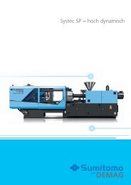
1. Mould being moved to compression gap 2. Melt being injected into a pre-enlarged cavity<br />
3. Melt being compressed by clamping movement of machine 4. Cooling, opening and ejection<br />
ICM moulds require special physical design<br />
F S<br />
F S<br />
F core<br />
F S<br />
: clamping force<br />
F core<br />
: stamping force<br />
Vertical flash face Stamping frame Stamping plug<br />
Principle and variants<br />
Basically, the sequences of the ICM process<br />
variants are similar and easy to understand<br />
because all the process involves is an additional<br />
stroke of the clamping unit:<br />
1. Close mould to compression gap.<br />
2. Inject and fill cavity 80 – 95 % (equivalent to<br />
100 % or more of the final volume)<br />
3. Sequential or simultaneous compression by<br />
the closing movement of the mould.<br />
4. Post-compression (if required), cooling,<br />
opening, and ejection<br />
Compression is effected either by the closing<br />
movement of the mould only or by the movement<br />
of an individual mould element activated<br />
by a hydraulic core pull function – called core<br />
stamping.<br />
New mould concepts<br />
Mould designs have recently been distinctly<br />
improved. The classic vertical flash face is increasingly<br />
being replaced by stamping-frame<br />
concepts or by designs of guided intermediate<br />
plates. In some cases, coining and stamping<br />
variants of ICM have established themselves.<br />
Compression and intermediate opening<br />
Aside from the basic functions, it is possible to<br />
use some additional options in injection compression<br />
moulding, for instance, pre-compression<br />
and intermediate opening. Pre-compression<br />
serves to form the decorating materials. Intermediate<br />
opening may be necessary where the<br />
mould is initially closed somewhat more than<br />
necessary for ICM in order to prevent jetting<br />
and ensure laminar flow during injection. Intermediate<br />
opening may also be helpful in foaming<br />
in order to permit expansion of the melt.<br />
3
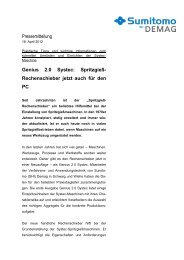
ICM CONTROL<br />
1 2<br />
3<br />
Variety and transparency<br />
Demag Plastics Group’s ICM control system is<br />
a selectable feature permitting a machine with<br />
ICM control to be used as a standard injection<br />
moulding machine. ICM control is available at<br />
two levels of sophistication:<br />
• As sequential ICM control with injection and<br />
compression taking place in sequence.<br />
• As simultaneous ICM control with compression<br />
taking place in parallel with injection<br />
and with pre-compression and intermediate<br />
opening functions.<br />
Sequential ICM control is essentially an extension<br />
of the NC4 or NC5 controller. As such it<br />
is available for all Demag machines of the Concept,<br />
System, Systec, IntElect, and Titan series.<br />
The extended ICM control, which imposes<br />
additional requirements on drive technology,<br />
can be integrated into the all-electric IntElect<br />
with out any problem. In the case of the hydraulic<br />
machines, it would be necessary to look into<br />
the cost of configuring the hydraulics in each<br />
specific case.<br />
Integration into the NC4 controller<br />
There are three screen pages in the NC4 control<br />
system of the Demag machines to manipulate<br />
injection compression moulding. The options<br />
summarised on the screen pages 9 (“ICM control”)<br />
and 8 (“Pre-compression/intermediate<br />
4<br />
opening”) are easy to understand. The ICM<br />
control is, of course, fully integrated in the<br />
screen page 18 (“Flexible machine sequence”).<br />
1 Screen page 9: ICM control<br />
The many options for modes, starting events,<br />
etc, are selected by means of drop-down<br />
menus. These provide the operator with a host<br />
of process variants through the use of different<br />
combinations. All important parameters, such<br />
as mould protection, compression speed, travel<br />
points, and many other functions are visible at<br />
a glance. As a protective function for the ICM<br />
process, ICM control provides monitoring time<br />
settings as well as delay time settings to 1/100<br />
second accuracy.<br />
2 Screen page 8:<br />
Pre-compression/intermediate opening<br />
Programming switches with monitoring and<br />
delay time settings are provided for precompression<br />
and intermediate opening as are<br />
various options for their starting events.<br />
3 Screen page 18:<br />
Flexible machine sequence<br />
All ICM functions, namely, compression, precompression<br />
and/or intermediate opening, and<br />
all associated movements are fully tied into the<br />
familiar presentation of machine sequences.<br />
Thus, the operator has the complete process<br />
sequences displayed on one page.
MACHINE TECHNOLOGY<br />
Stamping frame control via spring pre-stressing or core pull control<br />
Carriage fixing via locking circuit<br />
Spring pre-stressing<br />
+ Simple and low-cost system<br />
+ Small mould height<br />
– Pre-stressing force variable only<br />
by changing springs<br />
– Force line is non-linear<br />
Core pull control<br />
+ Linear force distribution<br />
+ Pre-stressing force variable<br />
+ Constant force distribution<br />
– Higher costs<br />
+ Hydromechanical locking of<br />
compression gap<br />
+ Stepped clamping force possible<br />
+ Carriage fi xing also with injection<br />
pressure increasing<br />
– Only possible on toggle machines<br />
– Additional hydraulic power pack<br />
required<br />
Merits and demerits of clamping principles in injection compression moulding have to be taken into account in selecting an injection moulding machine<br />
Full hydraulic injection moulding machine<br />
Toggle injection moulding machine<br />
+/0 Two/three-platen confi guration Design Three-platen confi guration 0<br />
+/0 Small/medium Space requirements Medium 0<br />
+ Hydraulic Clamping principle Hydromechanical ++<br />
++ 100 % of clamping force Compression force Abt. 50 % of clamping force –<br />
+ Exact, but no mechanical advantage Compression gap positioning Extremely accurate due to mechanical advantage of toggle ++<br />
0 Difficult, mainly when operating with small compression gaps Control of ICM stroke Good control also for small compression gaps ++<br />
+ Hydromechanical Force transmission Mechanical ++<br />
0 Hydraulic Carriage locking Hydromechanical +<br />
– None Clamping force reserve 10 – 15 % ++<br />
++ most advantageous + advantageous 0 indifferent – disadvantageous<br />
Full hydraulic and toggle<br />
By relying on the clamping unit of injection<br />
moulding machines ICM offers the advantage<br />
of a substantially higher force reserve compared<br />
to stamping plugs in the mould. In contrast<br />
to hydraulic two-platen machines, toggle clamp<br />
units transmit the force uniformly and centrally<br />
into the mould with – in contrast to widely held<br />
prejudices – a clearly sufficient compression<br />
force. The toggle has proved advantageous<br />
especially in filling asymmetrically arranged cavities<br />
or cavities with long-flow paths. The special<br />
kinematics of the toggle provide extremely<br />
accurate mould movements near the locking<br />
range and, consequently, permit highly accurate<br />
positioning for small compression gaps and<br />
efficient management of the ICM processes.<br />
The simultaneous variant of ICM control on<br />
Demag machines incorporates two interesting<br />
special functions: carriage fixing via locking<br />
circuit enables the crosshead of the toggle to<br />
be arrested, and the stamping frame acting<br />
via the core pull control can be operated by<br />
means of a hydraulic cylinder in order to obtain<br />
variable settings of a defined back pressure.<br />
ICM control retrofits<br />
ICM control is not limited to new machines.<br />
All existing Demag machines with an NC4 controller<br />
(DIAS or C-DIAS-CPU) can be retrofitted<br />
with the sequential ICM control. Retrofitting<br />
the extended ICM control on hydraulic machines<br />
mostly also calls for a hydraulic system<br />
retrofit.<br />
5
APPLICATIONS<br />
IMD parts<br />
Mechanically loaded LFT parts<br />
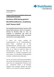
Clamp force reduction when moulding PP by ICM process<br />
IMD parts<br />
Thin-walled packaging articles<br />
Clamp force (kN)<br />
10000<br />
9000<br />
8000<br />
7000<br />
6000<br />
5000<br />
4000<br />
3000<br />
2000<br />
1000<br />
0<br />
Injection moulding ICM<br />
Flow behaviour easy poor easy poor<br />
Type of process<br />
Injection moulding ICM<br />
Compression rate (%) - - 99 99<br />
Clamp force (kN) 8,500 9,500 5,000 6,000<br />
ICM in practice<br />
The number of ICM applications is increa sing –<br />
for IMD-decorated parts, for mechanically<br />
loaded plastic elements in automobile building,<br />
for very thin-walled packaging articles, for<br />
optical and foamed parts as well as for moulded<br />
parts with a finely textured surface or<br />
for direct back injection for textiles, etc, for<br />
decorative components. In the case of many<br />
important applications, injection compression<br />
moulding provides positive technical or<br />
economical benefits.<br />
IMD parts: In the case of in-mould decoration<br />
(IMD), ICM reduces film stresses during<br />
filling and creasing in the border areas of the<br />
moulded part because it permits the film to<br />
smooth out at critical points. ICM also improves<br />
surface appearance.<br />
6<br />
Mechanically loaded LFT parts: ICM reduces<br />
fibre degradation during injection and reduces<br />
the susceptibility of the moulded part to warping.<br />
In addition it improves mechanical properties,<br />
reduces mould wear, and generally shortens<br />
cycle time.<br />
Thin-walled packaging products: ICM, when<br />
applied to thin-walled packaging products tends<br />
to further reduce the necessary injection pressure<br />
and minimal wall thicknesses and, con sequently,<br />
to further increase the possible flow-distance/<br />
wall-thickness ratios. ICM im proves venting of<br />
the mould and, in the case of inmould labelling<br />
(IML), reduces the stressing of labels and inserts.<br />
Overlapping of clamping and injection movements<br />
is apt to further reduce cycle time in the<br />
case of fast-cycling injection moulding.<br />
Optical moulded parts: Faster injection<br />
into the open mould, the possibility of overpacking<br />
– in order to control shrinkage right<br />
from the start – as well as the very uniform and<br />
long-action holding pressure in injection compression<br />
moulding combine to reduce internal<br />
stresses in the moulded part, and improve its<br />
optical properties and light defraction.<br />
Direct back-injected parts: The reduction in<br />
injection pressure reduces stresses in films or<br />
mats in direct backing injection and reduces<br />
the problem of creasing. Due to the lower<br />
clam ping force required, it is possible to mould<br />
larger components on a wide-platen machine.<br />
Generally, ICM offers greater freedom to the<br />
designer when applied to backing injection<br />
decoration. ICM control permits preforming of
Advantage of process through overpacking<br />
Injection moulding<br />
ICM<br />
Cavity filling<br />
95 – 98 % cavity volume<br />
100 % fi nal volume<br />
holding pressure<br />
Change-over point<br />
Possible filling volume<br />
Compensating shrinkage<br />
80 – 90 % cavity volume<br />
>100 % final volume<br />
Compression +<br />
holding pressure<br />
Optical moulded parts<br />
Injection pressure reduction through ICM applied to direct backing injection<br />
Maximum injection pressure (bar)<br />
900<br />
800<br />
700<br />
600<br />
500<br />
400<br />
300<br />
200<br />
100<br />
0<br />
Decorative backing-injected parts<br />
Foamed moulded parts<br />
Standard injection moulding with hold pressure (2s/400 bar)<br />
ICM start injection<br />
ICM start hold pressure (V=1 %)<br />
ICM start hold pressure (V=99 %) easy fl ow<br />
ICM start hold pressure (V=99 %) poor fl ow<br />
the decorative materials by means of a preceding<br />
compression stroke.<br />
Finely textured surfaces: ICM moulding<br />
en sures exact and uniform duplication of microtextures<br />
on the moulded part surface – especially<br />
at the end of the flow path. It facilitates<br />
combining different textures and improves the<br />
degree of reproduction.<br />
Foamed parts: Intermediate opening prevents<br />
premature foaming of the melt, where chemical<br />
blowing agents have been added or mechanical<br />
blowing has been applied. The more homogenous<br />
pressure conditions in the mould and the<br />
more uniform holding pressure have an influence<br />
on the cell structure and improve venting<br />
as well as surface quality.<br />
Finely textured surfaces<br />
7
Asia<br />
Demag (Malaysia) Sdn Bhd<br />
15-E, 5th Floor, Block 1<br />
Worldwide Business Park<br />
Jalan 13/50, Section 13<br />
40000 Shah Alam<br />
Selangor Darul Ehsan, Malaysia<br />
Tel.: +60-3-55 12 97 40<br />
Fax: +60-3-55 12 97 60<br />
E-Mail: dpa@demag.com.my<br />
Brazil<br />
Demag Ergotech Brasil Ltda.<br />
Av. Ceci, 608 – Galpao B11<br />
Tamboré<br />
06460-120 Barueri (SP)<br />
Tel.: +55-11-41 95-41 12<br />
Fax: +55-11-41 95-41 13<br />
E-Mail: brasil@demag-ergotech.com.br<br />
China<br />
Demag Plastics Machinery (Ningbo) Co., Ltd.<br />
No.669, Kunlunshan Road, Beilun District,<br />
Ningbo, 315800, Zhejiang Province, P.R.China<br />
Tel.: +86-5 74-86 18 15 00<br />
Fax: +86-5 74-86 18 15 18<br />
E-Mail: sales.cn@dpg.com<br />
China<br />
Demag Ergotech GmbH<br />
Shanghai Rep. Offi ce<br />
6F, No. 1221, Hami Road,<br />
Shanghai 200335, China<br />
Tel.: +86-21-52 19 50 00<br />
Fax: +86-21-52 19 62 50<br />
E-Mail: shanghai@demag-ergotech.com.cn<br />
CIS<br />
Mannesmann Demag Plastservice<br />
Prombaza OAO „Stroitransgaz“<br />
d.Ascherino<br />
Leninskiy raion<br />
142717 Moscow region<br />
Tel.: +74-95-9 37 97 64<br />
Fax: +74-95-9 33 00 78<br />
E-Mail: info.plastservice@dpg.com<br />
France<br />
Demag Ergotech France sas<br />
Zac du Mandinet<br />
9, rue des Campanules<br />
77185 Lognes<br />
Tel.: +33-1-60 33 20 10<br />
Fax: +33-1-60 06 28 89<br />
E-Mail: detf@dpg.com<br />
Germany<br />
Demag Ergotech GmbH<br />
Werk Schwaig<br />
Altdorfer Str. 15<br />
90571 Schwaig<br />
Tel.: +49-9 11-50 61-0<br />
Fax: +49-9 11-50 61-2 65<br />
E-Mail: info-dpde@dpg.com<br />
Germany<br />
Demag Ergotech GmbH<br />
Werk Wiehe<br />
Donndorfer Str. 3<br />
06571 Wiehe<br />
Tel.: +49-3 46 72-97-0<br />
Fax: +49-3 46 72-97-333<br />
E-Mail: info-dpde@dpg.com<br />
India<br />
L&T-Demag Plastics Machinery Limited<br />
Mount-Poonamallee Road<br />
Manapakkam/Chennai 600 089<br />
Tel.: +91-44-22 49-04 32<br />
Fax: +91-44-22 49-49 52<br />
E-Mail: nss@Itdemag.com<br />
Italy<br />
Demag Plastics Group Italia s.r.l.<br />
Via Bassano 3<br />
03012 Anagni (FR)<br />
Tel.: +39-07 75-77 20 04<br />
Fax: +39-07 75-77 20 04<br />
E-Mail: lido.ghirlandini@dpg.com<br />
Poland<br />
Demag Plastics Group Sp. z o.o.<br />
ul. Jagiellońska 81-83<br />
42-200 Częstochowa<br />
Tel.: +48-34-3 70 95 40<br />
Fax: +48-34-3 70 94 86<br />
E-Mail: info@demag.pl<br />
Spain<br />
Demag Ergotech España, S.L.<br />
Pol. Ind. Can Calderón<br />
Avd. Riera de Fonollar<br />
Esquina C/Murcia, n°37-A, Nave F<br />
08830 – Sant Boi de Llobregat (Barcelona)<br />
Tel.: +34-93-6 52 95 30<br />
Fax: +34-93-6 54 78 10<br />
E-Mail: angel.lozano@dpg.com<br />
United Kingdom<br />
Demag Hamilton Ltd.<br />
Hamilton House, Broadfi elds<br />
Bicester Road, Aylesbury<br />
Bucks, HP19 8AY<br />
Tel.: +44-12 96-31 82 00<br />
Fax: +44-12 96-42 62 22<br />
E-Mail: salesUK@dpg.com<br />
USA<br />
Demag Plastics Group Corp.<br />
11792 Alameda Drive<br />
Strongsville, Ohio 44149-3011<br />
Tel.: +1-4 40-8 76-89 48<br />
Fax: +1-4 40-8 76-64 39<br />
E-Mail: info-dc@dpg.com<br />
The responsibility to ensure that everything<br />
runs smoothly<br />
Many moulders today operate three shifts, some on 365 days of the<br />
year – this calls for a maximum of availability of the machines, spare<br />
parts, and service support.<br />
Backed by highly skilled service teams, advanced spare parts logistics, and<br />
multiple service levels to address a customer’s specific needs, we provide<br />
total support world-wide: from straightforward inspections through comprehensive<br />
maintenance, and extended warranties for high capacity<br />
utilisation levels to emergency hotline support, and training of your<br />
personnel.<br />
Full documentation and a digital catalogue ensure that spare parts are<br />
delivered to you in a minimum of time, usually within a few hours. Users<br />
of older machines can have them upgraded by our retrofit service at fair<br />
prices, for instance, by state-of-the-art control software or for specialised<br />
injection-moulding processes. In short, the Demag Service provides you<br />
with whatever support you need to complete your jobs efficiently and<br />
to schedule.<br />
3091 Spritzprägen-GB 1007 he www.da-kapo.de<br />
www.dpg.com