- Page 2 and 3:
ISPSoft User Manual Preface ISPSoft
- Page 4 and 5:
Chapter 1 Introduction of the Softw
- Page 6 and 7:
Chapter 1 Introduction of the Softw
- Page 8 and 9:
Chapter 1 Introduction of the Softw
- Page 10 and 11:
Chapter 1 Introduction of the Softw
- Page 12 and 13:
Chapter 1 Introduction of the Softw
- Page 14 and 15:
Chapter 2 Starting and Setting Tabl
- Page 16 and 17:
Chapter 2 Starting and Setting Afte
- Page 18 and 19:
Chapter 2 Starting and Setting Win
- Page 20 and 21:
Chapter 2 Starting and Setting •
- Page 22 and 23:
Chapter 2 Starting and Setting •
- Page 24 and 25:
Chapter 2 Starting and Setting they
- Page 26 and 27:
Chapter 2 Starting and Setting •
- Page 28 and 29:
Chapter 2 Starting and Setting *1.
- Page 30 and 31:
Chapter 2 Starting and Setting User
- Page 32 and 33:
Chapter 2 Starting and Setting File
- Page 34 and 35:
Chapter 2 Starting and Setting Afte
- Page 36 and 37:
Chapter 2 Starting and Setting •
- Page 38 and 39:
Chapter 2 Starting and Setting Afte
- Page 40 and 41:
Chapter 2 Starting and Setting In t
- Page 42 and 43:
Chapter 2 Starting and Setting Afte
- Page 44 and 45:
Chapter 2 Starting and Setting •
- Page 46 and 47:
Chapter 2 Starting and Setting •
- Page 48 and 49:
Chapter 2 Starting and Setting *. I
- Page 50 and 51:
Chapter 2 Starting and Setting Afte
- Page 52 and 53:
Chapter 2 Starting and Setting ‣
- Page 54 and 55:
Chapter 2 Starting and Setting 2.4.
- Page 56 and 57:
Chapter 2 Starting and Setting Numb
- Page 58 and 59:
Chapter 2 Starting and Setting they
- Page 60 and 61:
Chapter 2 Starting and Setting (5)
- Page 62 and 63:
Chapter 2 Starting and Setting Addi
- Page 64 and 65:
Chapter 3 Configuring and Setting a
- Page 66 and 67:
ISPSoft User Manual By means of the
- Page 68 and 69:
ISPSoft User Manual (6) If the user
- Page 70 and 71:
ISPSoft User Manual 3.2 Hardware Co
- Page 72 and 73:
ISPSoft User Manual All hardware av
- Page 74 and 75:
ISPSoft User Manual • Method 3 (1
- Page 76 and 77:
ISPSoft User Manual • AH16AM10N-5
- Page 78 and 79:
ISPSoft User Manual *. Please refer
- Page 80 and 81:
ISPSoft User Manual 3.2.2.4 Deletin
- Page 82 and 83:
ISPSoft User Manual 3.2.2.6 Searchi
- Page 84 and 85:
ISPSoft User Manual *. If the Repla
- Page 86 and 87:
ISPSoft User Manual There are two w
- Page 88 and 89:
ISPSoft User Manual • Method 2 (1
- Page 90 and 91:
ISPSoft User Manual *. An extension
- Page 92 and 93:
ISPSoft User Manual 3.2.2.12 Replac
- Page 94 and 95:
ISPSoft User Manual system configur
- Page 96 and 97:
ISPSoft User Manual 3.3 Setting the
- Page 98 and 99:
ISPSoft User Manual Users can ident
- Page 100 and 101:
ISPSoft User Manual • Enable Remo
- Page 102 and 103:
ISPSoft User Manual value and a min
- Page 104 and 105:
ISPSoft User Manual If the sending
- Page 106 and 107:
ISPSoft User Manual • Enable Stat
- Page 108 and 109:
ISPSoft User Manual After users sel
- Page 110 and 111:
ISPSoft User Manual every specific
- Page 112 and 113:
ISPSoft User Manual (5) After all t
- Page 114 and 115:
ISPSoft User Manual The parameters
- Page 116 and 117:
ISPSoft User Manual *1. The paramet
- Page 118 and 119:
ISPSoft User Manual If users want t
- Page 120 and 121:
ISPSoft User Manual There are two t
- Page 122 and 123:
ISPSoft User Manual parameter in a
- Page 124 and 125:
ISPSoft User Manual *1. DCISoft ver
- Page 126 and 127:
ISPSoft User Manual After Export on
- Page 128 and 129:
ISPSoft User Manual window will app
- Page 130 and 131:
ISPSoft User Manual different from
- Page 132 and 133:
ISPSoft User Manual If users right-
- Page 134 and 135:
ISPSoft User Manual (2) The present
- Page 136 and 137:
ISPSoft User Manual (2) If the time
- Page 138 and 139:
Chapter 4 Quick Start Table of Cont
- Page 140 and 141:
Chapter 4 Quick Start (2) When in p
- Page 142 and 143:
Chapter 4 Quick Start If users want
- Page 144 and 145:
Chapter 4 Quick Start After the use
- Page 146 and 147:
Chapter 4 Quick Start 4.5.1 Adding
- Page 148 and 149:
Chapter 4 Quick Start (2) Click on
- Page 150 and 151:
Chapter 4 Quick Start Additional re
- Page 152 and 153:
Chapter 4 Quick Start Additional re
- Page 154 and 155:
Chapter 4 Quick Start (2) Select ne
- Page 156 and 157:
Chapter 4 Quick Start 4.5.7 Basic E
- Page 158 and 159: Chapter 4 Quick Start 4.5.8 Basic E
- Page 160 and 161: Chapter 4 Quick Start *1. The progr
- Page 162 and 163: Chapter 4 Quick Start Automation>Co
- Page 164 and 165: Chapter 4 Quick Start 4.6.2 Downloa
- Page 166 and 167: Chapter 4 Quick Start 4.6.3 Connect
- Page 168 and 169: Chapter 4 Quick Start If users want
- Page 170 and 171: Chapter 4 Quick Start Right-click D
- Page 172 and 173: Chapter 4 Quick Start The program c
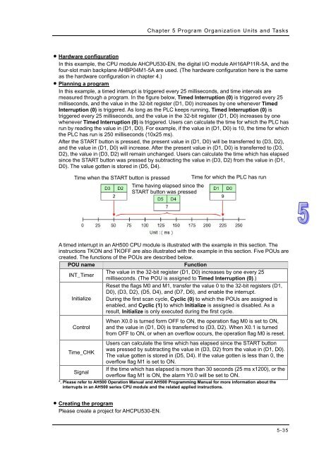
- Page 174 and 175: Chapter 5 Program Organization Unit
- Page 176 and 177: Chapter 5 Program Organization Unit
- Page 178 and 179: Chapter 5 Program Organization Unit
- Page 180 and 181: Chapter 5 Program Organization Unit
- Page 182 and 183: Chapter 5 Program Organization Unit
- Page 184 and 185: Chapter 5 Program Organization Unit
- Page 186 and 187: Chapter 5 Program Organization Unit
- Page 188 and 189: Chapter 5 Program Organization Unit
- Page 190 and 191: Chapter 5 Program Organization Unit
- Page 192 and 193: Chapter 5 Program Organization Unit
- Page 194 and 195: Chapter 5 Program Organization Unit
- Page 196 and 197: Chapter 5 Program Organization Unit
- Page 198 and 199: Chapter 5 Program Organization Unit
- Page 200 and 201: Chapter 5 Program Organization Unit
- Page 202 and 203: Chapter 5 Program Organization Unit
- Page 204 and 205: Chapter 5 Program Organization Unit
- Page 206 and 207: Chapter 5 Program Organization Unit
- Page 210 and 211: Chapter 5 Program Organization Unit
- Page 212 and 213: Chapter 5 Program Organization Unit
- Page 214 and 215: Chapter 5 Program Organization Unit
- Page 216 and 217: Chapter 5 Program Organization Unit
- Page 218 and 219: Chapter 6 Symbols Table of Contents
- Page 220 and 221: Chapter 6 Symbols • VAR-General s
- Page 222 and 223: Chapter 6 Symbols 6.1.4 Assigning a
- Page 224 and 225: Chapter 6 Symbols Application Examp
- Page 226 and 227: Chapter 6 Symbols • Local symbol
- Page 228 and 229: Chapter 6 Symbols • STRING If the
- Page 230 and 231: Chapter 6 Symbols • Auto-close Di
- Page 232 and 233: Chapter 6 Symbols double quotes, an
- Page 234 and 235: Chapter 6 Symbols *. Before the ini
- Page 236 and 237: Chapter 6 Symbols Select a file whi
- Page 238 and 239: Chapter 6 Symbols Press Alt+ on the
- Page 240 and 241: Chapter 6 Symbols Users can set a d
- Page 242 and 243: Chapter 6 Symbols Double-click RUN_
- Page 244 and 245: Chapter 6 Symbols If users want to
- Page 246 and 247: Chapter 7 Function Block Table of C
- Page 248 and 249: Chapter 7 Function Block 7.1.2 Char
- Page 250 and 251: Chapter 7 Function Block Class VAR_
- Page 252 and 253: Chapter 7 Function Block P_VAR (cal
- Page 254 and 255: Chapter 7 Function Block The princi
- Page 256 and 257: Chapter 7 Function Block *. SM400 i
- Page 258 and 259:
Chapter 7 Function Block In view of
- Page 260 and 261:
Chapter 7 Function Block itself. As
- Page 262 and 263:
Chapter 7 Function Block • DVP se
- Page 264 and 265:
Chapter 7 Function Block Function b
- Page 266 and 267:
Chapter 7 Function Block HC_POINTER
- Page 268 and 269:
Chapter 7 Function Block program in
- Page 270 and 271:
Chapter 7 Function Block The functi
- Page 272 and 273:
Chapter 7 Function Block Please ref
- Page 274 and 275:
Chapter 7 Function Block After the
- Page 276 and 277:
Chapter 7 Function Block Open the w
- Page 278 and 279:
Chapter 7 Function Block Obviously,
- Page 280 and 281:
Chapter 8 Ladder Diagram Table of C
- Page 282 and 283:
Chapter 8 Ladder Diagram Local symb
- Page 284 and 285:
Chapter 8 Ladder Diagram Selecting
- Page 286 and 287:
Chapter 8 Ladder Diagram (4) After
- Page 288 and 289:
Chapter 8 Ladder Diagram (b) ‣ Bo
- Page 290 and 291:
Chapter 8 Ladder Diagram Users can
- Page 292 and 293:
Chapter 8 Ladder Diagram (2) Select
- Page 294 and 295:
Chapter 8 Ladder Diagram (2) Click
- Page 296 and 297:
Chapter 8 Ladder Diagram The steps
- Page 298 and 299:
Chapter 8 Ladder Diagram 8.2.10 Sym
- Page 300 and 301:
Chapter 8 Ladder Diagram The networ
- Page 302 and 303:
Chapter 9 Function Block Diagram Ta
- Page 304 and 305:
Chapter 9 Function Block Diagram Lo
- Page 306 and 307:
Chapter 9 Function Block Diagram T
- Page 308 and 309:
Chapter 9 Function Block Diagram (e
- Page 310 and 311:
Chapter 9 Function Block Diagram In
- Page 312 and 313:
Chapter 9 Function Block Diagram Ex
- Page 314 and 315:
Chapter 9 Function Block Diagram fo
- Page 316 and 317:
Chapter 9 Function Block Diagram fu
- Page 318 and 319:
Chapter 9 Function Block Diagram Ex
- Page 320 and 321:
Chapter 9 Function Block Diagram Ex
- Page 322 and 323:
Chapter 9 Function Block Diagram an
- Page 324 and 325:
Chapter 9 Function Block Diagram
- Page 326 and 327:
Chapter 9 Function Block Diagram If
- Page 328 and 329:
Chapter 9 Function Block Diagram Ri
- Page 330 and 331:
Chapter 10 Instruction List Table o
- Page 332 and 333:
Chapter 10 Instruction List The ope
- Page 334 and 335:
Chapter 10 Instruction List • As
- Page 336 and 337:
Chapter 10 Instruction List If user
- Page 338 and 339:
Chapter 10 Instruction List Users
- Page 340 and 341:
Chapter 10 Instruction List 10.2.4.
- Page 342 and 343:
Chapter 11 Structured Text Table of
- Page 344 and 345:
Chapter 11 Structured Text A comple
- Page 346 and 347:
Chapter 11 Structured Text Data for
- Page 348 and 349:
Chapter 11 Structured Text However,
- Page 350 and 351:
Chapter 11 Structured Text Example
- Page 352 and 353:
Chapter 11 Structured Text Example
- Page 354 and 355:
Chapter 11 Structured Text Example
- Page 356 and 357:
Chapter 11 Structured Text 11.2.5 L
- Page 358 and 359:
Chapter 11 Structured Text 11.2.7 A
- Page 360 and 361:
Chapter 11 Structured Text Example
- Page 362 and 363:
Chapter 11 Structured Text larger t
- Page 364 and 365:
Chapter 11 Structured Text 11.3.3 I
- Page 366 and 367:
Chapter 11 Structured Text 11.4 Exa
- Page 368 and 369:
Chapter 11 Structured Text Create t
- Page 370 and 371:
Chapter 11 Structured Text which is
- Page 372 and 373:
Chapter 12 Sequential Function Char
- Page 374 and 375:
Chapter 12 Sequential Function Char
- Page 376 and 377:
Chapter 12 Sequential Function Char
- Page 378 and 379:
Chapter 12 Sequential Function Char
- Page 380 and 381:
Chapter 12 Sequential Function Char
- Page 382 and 383:
Chapter 12 Sequential Function Char
- Page 384 and 385:
Chapter 12 Sequential Function Char
- Page 386 and 387:
Chapter 12 Sequential Function Char
- Page 388 and 389:
Chapter 12 Sequential Function Char
- Page 390 and 391:
Chapter 12 Sequential Function Char
- Page 392 and 393:
Chapter 12 Sequential Function Char
- Page 394 and 395:
Chapter 12 Sequential Function Char
- Page 396 and 397:
Chapter 12 Sequential Function Char
- Page 398 and 399:
Chapter 12 Sequential Function Char
- Page 400 and 401:
Chapter 12 Sequential Function Char
- Page 402 and 403:
Chapter 12 Sequential Function Char
- Page 404 and 405:
Chapter 12 Sequential Function Char
- Page 406 and 407:
Chapter 12 Sequential Function Char
- Page 408 and 409:
Chapter 12 Sequential Function Char
- Page 410 and 411:
Chapter 12 Sequential Function Char
- Page 412 and 413:
Chapter 13 Auxiliary Editing Tools
- Page 414 and 415:
Chapter 13 Auxiliary Editing Tools
- Page 416 and 417:
Chapter 13 Auxiliary Editing Tools
- Page 418 and 419:
Chapter 13 Auxiliary Editing Tools
- Page 420 and 421:
Chapter 13 Auxiliary Editing Tools
- Page 422 and 423:
Chapter 13 Auxiliary Editing Tools
- Page 424 and 425:
Chapter 13 Auxiliary Editing Tools
- Page 426 and 427:
Chapter 13 Auxiliary Editing Tools
- Page 428 and 429:
Chapter 13 Auxiliary Editing Tools
- Page 430 and 431:
Chapter 13 Auxiliary Editing Tools
- Page 432 and 433:
Chapter 13 Auxiliary Editing Tools
- Page 434 and 435:
Chapter 13 Auxiliary Editing Tools
- Page 436 and 437:
Chapter 13 Auxiliary Editing Tools
- Page 438 and 439:
Chapter 13 Auxiliary Editing Tools
- Page 440 and 441:
Chapter 13 Auxiliary Editing Tools
- Page 442 and 443:
Chapter 13 Auxiliary Editing Tools
- Page 444 and 445:
Chapter 13 Auxiliary Editing Tools
- Page 446 and 447:
Chapter 13 Auxiliary Editing Tools
- Page 448 and 449:
Chapter 13 Auxiliary Editing Tools
- Page 450 and 451:
Chapter 13 Auxiliary Editing Tools
- Page 452 and 453:
Chapter 14 Test Tools and Debugging
- Page 454 and 455:
Chapter 14 Test Tools and Debugging
- Page 456 and 457:
Chapter 14 Test Tools and Debugging
- Page 458 and 459:
Chapter 14 Test Tools and Debugging
- Page 460 and 461:
Chapter 14 Test Tools and Debugging
- Page 462 and 463:
Chapter 14 Test Tools and Debugging
- Page 464 and 465:
Chapter 14 Test Tools and Debugging
- Page 466 and 467:
Chapter 14 Test Tools and Debugging
- Page 468 and 469:
Chapter 14 Test Tools and Debugging
- Page 470 and 471:
Chapter 14 Test Tools and Debugging
- Page 472 and 473:
Chapter 14 Test Tools and Debugging
- Page 474 and 475:
Chapter 14 Test Tools and Debugging
- Page 476 and 477:
Chapter 14 Test Tools and Debugging
- Page 478 and 479:
Chapter 14 Test Tools and Debugging
- Page 480 and 481:
Chapter 14 Test Tools and Debugging
- Page 482 and 483:
Chapter 14 Test Tools and Debugging
- Page 484 and 485:
Chapter 14 Test Tools and Debugging
- Page 486 and 487:
Chapter 14 Test Tools and Debugging
- Page 488 and 489:
Chapter 15 Password Management and
- Page 490 and 491:
Chapter 15 Password Management and
- Page 492 and 493:
Chapter 15 Password Management and
- Page 494 and 495:
Chapter 15 Password Management and
- Page 496 and 497:
Chapter 15 Password Management and
- Page 498 and 499:
Chapter 15 Password Management and
- Page 500 and 501:
Chapter 15 Password Management and
- Page 502 and 503:
Chapter 16 Network Configuration an
- Page 504 and 505:
ISPSoft User Manual 16.1 Network Co
- Page 506 and 507:
ISPSoft User Manual DHCP is a proto
- Page 508 and 509:
ISPSoft User Manual NWCONFIG can al
- Page 510 and 511:
ISPSoft User Manual address or RS-4
- Page 512 and 513:
ISPSoft User Manual (4) Complete a
- Page 514 and 515:
ISPSoft User Manual The users can a
- Page 516 and 517:
ISPSoft User Manual There are two w
- Page 518 and 519:
ISPSoft User Manual • Method 2 Cl
- Page 520 and 521:
ISPSoft User Manual Additional rema
- Page 522 and 523:
ISPSoft User Manual • Deleting a
- Page 524 and 525:
ISPSoft User Manual • Deleting se
- Page 526 and 527:
ISPSoft User Manual (b) After users
- Page 528 and 529:
ISPSoft User Manual In the Network
- Page 530 and 531:
ISPSoft User Manual • Hiding/Disp
- Page 532 and 533:
ISPSoft User Manual The system chec
- Page 534 and 535:
ISPSoft User Manual station address
- Page 536 and 537:
ISPSoft User Manual After the users
- Page 538 and 539:
ISPSoft User Manual (4) After the d
- Page 540 and 541:
ISPSoft User Manual • Method 3 Ri
- Page 542 and 543:
ISPSoft User Manual boxes at the le
- Page 544 and 545:
ISPSoft User Manual Column Serial N
- Page 546 and 547:
ISPSoft User Manual • Linked Devi
- Page 548 and 549:
ISPSoft User Manual Related setting
- Page 550 and 551:
ISPSoft User Manual The present net
- Page 552 and 553:
ISPSoft User Manual Setting area:
- Page 554 and 555:
ISPSoft User Manual The indicators
- Page 556 and 557:
ISPSoft User Manual Users can type
- Page 558 and 559:
ISPSoft User Manual An Ether Link i
- Page 560 and 561:
ISPSoft User Manual Information ar
- Page 562 and 563:
ISPSoft User Manual (5) Type a data
- Page 564 and 565:
ISPSoft User Manual If a specific n
- Page 566 and 567:
ISPSoft User Manual • Method 2 Do
- Page 568 and 569:
ISPSoft User Manual • Multiple no
- Page 570 and 571:
ISPSoft User Manual • Multiple no
- Page 572 and 573:
ISPSoft User Manual 16.4.9 Enabling
- Page 574 and 575:
ISPSoft User Manual Additional rema
- Page 576 and 577:
ISPSoft User Manual 16.4.10 Startin
- Page 578 and 579:
ISPSoft User Manual ‣ Method 2 Se
- Page 580 and 581:
ISPSoft User Manual After a node is
- Page 582 and 583:
ISPSoft User Manual 16.5.2.2 Descri
- Page 584 and 585:
ISPSoft User Manual (1) Users have
- Page 586 and 587:
Chapter 17 Data Backup and Data Res
- Page 588 and 589:
Chapter 17 Data Backup and Data Res
- Page 590 and 591:
Chapter 17 Data Backup and Data Res
- Page 592 and 593:
Chapter 17 Data Backup and Data Res
- Page 594 and 595:
Chapter 17 Data Backup and Data Res
- Page 596 and 597:
Chapter 17 Data Backup and Data Res
- Page 598 and 599:
Appendix A USB Connection Table of
- Page 600 and 601:
Appendix A USB Connection Specify a
- Page 602 and 603:
Appendix A USB Connection *. The de
- Page 604 and 605:
Appendix A USB Connection If the de
- Page 606 and 607:
Appendix B Important Points Related
- Page 608 and 609:
Appendix B Important Points Related
- Page 610 and 611:
Appendix B Important Points Related
- Page 612 and 613:
Appendix B Important Points Related
- Page 614 and 615:
Appendix C Print Management Tool Ta
- Page 616 and 617:
Appendix C Print Management Tool C.