ISPSoft User Manual
ISPSoft User Manual ISPSoft User Manual
Chapter 4 Quick Start Table of Contents 4.1 Quick Start.................................................................................................4-2 4.1.1 Example .............................................................................................4-2 4.1.2 Hardware............................................................................................4-2 4.1.3 Program .............................................................................................4-2 4.2 Procedure for Creating a Project in ISPSoft ..............................................4-3 4.3 Creating a Project......................................................................................4-3 4.4 Hardware Configuration.............................................................................4-4 4.4.1 Configuring a Module .........................................................................4-4 4.4.2 Setting the Parameters in a CPU Module and a Module ....................4-6 4.5 Creating a Program ...................................................................................4-8 4.5.1 Adding a Ladder Diagram ..................................................................4-9 4.5.2 Basic Editing─Creating a Contact and a Coil ...................................4-10 4.5.3 Basic Editing─Inserting a Network and Typing an Instruction ..........4-13 4.5.4 Basic Editing─Selection of a Network and Operation.......................4-15 4.5.5 Basic Editing─Connecting a Contact in Parallel...............................4-17 4.5.6 Basic Editing─Editing a Comment....................................................4-18 4.5.7 Basic Editing─Inserting an Applied Instruction.................................4-19 4.5.8 Basic Editing─Creating a Comparison Contact and Typing a Constant .........................................................................................................4-21 4.5.9 Writing a Program ............................................................................4-22 4.5.10 Checking and Compiling a Program.................................................4-23 4.6 Testing and Debugging a Program..........................................................4-24 4.6.1 Creating a Connection......................................................................4-24 4.6.2 Downloading a Program and Parameters ........................................4-27 4.6.3 Connection Test ...............................................................................4-29 4-1
ISPSoft User Manual 4.1 Quick Start The chapter provides a simple example, and leads users to create a traditional ladder diagram in ISPSoft in a short time. However, in order to help users who are not familiar with IEC 61131-3 understand the functions provided by ISPSoft, and create a traditional ladder diagram, programming concepts related to IEC 61131-3 are not introduced in this chapter. For example, POUs, function blocks, variables, and etc. are not introduced. The concepts related to IEC 61131-3 will be introduced in the following chapters. 4.1.1 Example When the equipment operates, the parts on the conveyer are conveyed from left to right. If a sensor senses that a part is under an injector, the PLC will send a trigger signal to the injector, and the injector will injects the glue. How long the part will be injected is set externally, and is not controlled by the program in the PLC. However, the program in the PLC must be able to turn the trigger signal OFF so that the trigger signal can be sent next time. There are two injectors above the conveyer, and the two injectors inject glue in the same way. Besides, there is a sensor at the left side of the conveyer. When a part passes the sensor, the sensor value increases by one increment. If the sensor value is 100, the internal completion flag will be set to ON. The state of the flag can be used by other procedures later. However, the use of the state of the flag is not introduced in this example. 4.1.2 Hardware In this example, the AH500 series CPU module used is AHCPU530-EN, the digital I/O module used is AH16AP11R-5A, and the main backplane used is AHBP04M1-5A. The table below is an I/O allocation table. Type ID Description Digital input X0.0 START button Digital input X0.1 STOP button Digital input X0.2 In position sensor 1 Digital input X0.3 In position sensor 2 Digital input X0.4 Counting sensor Digital output Y0.0 Conveyer Digital output Y0.1 Trigger signal for injector 1 Digital output Y0.2 Trigger signal for injector 2 4.1.3 Program (1) When the START button (X0.0) is turned from OFF to ON, the internal operation flag is set to ON, and the conveyer (Y0.0) starts to run. When the STOP button (X0.1) is turned from OFF to ON, an error occurs (the error flag is ON), the operation flag is reset to OFF, and the conveyer stops running. 4-2
- Page 88 and 89: ISPSoft User Manual • Method 2 (1
- Page 90 and 91: ISPSoft User Manual *. An extension
- Page 92 and 93: ISPSoft User Manual 3.2.2.12 Replac
- Page 94 and 95: ISPSoft User Manual system configur
- Page 96 and 97: ISPSoft User Manual 3.3 Setting the
- Page 98 and 99: ISPSoft User Manual Users can ident
- Page 100 and 101: ISPSoft User Manual • Enable Remo
- Page 102 and 103: ISPSoft User Manual value and a min
- Page 104 and 105: ISPSoft User Manual If the sending
- Page 106 and 107: ISPSoft User Manual • Enable Stat
- Page 108 and 109: ISPSoft User Manual After users sel
- Page 110 and 111: ISPSoft User Manual every specific
- Page 112 and 113: ISPSoft User Manual (5) After all t
- Page 114 and 115: ISPSoft User Manual The parameters
- Page 116 and 117: ISPSoft User Manual *1. The paramet
- Page 118 and 119: ISPSoft User Manual If users want t
- Page 120 and 121: ISPSoft User Manual There are two t
- Page 122 and 123: ISPSoft User Manual parameter in a
- Page 124 and 125: ISPSoft User Manual *1. DCISoft ver
- Page 126 and 127: ISPSoft User Manual After Export on
- Page 128 and 129: ISPSoft User Manual window will app
- Page 130 and 131: ISPSoft User Manual different from
- Page 132 and 133: ISPSoft User Manual If users right-
- Page 134 and 135: ISPSoft User Manual (2) The present
- Page 136 and 137: ISPSoft User Manual (2) If the time
- Page 140 and 141: Chapter 4 Quick Start (2) When in p
- Page 142 and 143: Chapter 4 Quick Start If users want
- Page 144 and 145: Chapter 4 Quick Start After the use
- Page 146 and 147: Chapter 4 Quick Start 4.5.1 Adding
- Page 148 and 149: Chapter 4 Quick Start (2) Click on
- Page 150 and 151: Chapter 4 Quick Start Additional re
- Page 152 and 153: Chapter 4 Quick Start Additional re
- Page 154 and 155: Chapter 4 Quick Start (2) Select ne
- Page 156 and 157: Chapter 4 Quick Start 4.5.7 Basic E
- Page 158 and 159: Chapter 4 Quick Start 4.5.8 Basic E
- Page 160 and 161: Chapter 4 Quick Start *1. The progr
- Page 162 and 163: Chapter 4 Quick Start Automation>Co
- Page 164 and 165: Chapter 4 Quick Start 4.6.2 Downloa
- Page 166 and 167: Chapter 4 Quick Start 4.6.3 Connect
- Page 168 and 169: Chapter 4 Quick Start If users want
- Page 170 and 171: Chapter 4 Quick Start Right-click D
- Page 172 and 173: Chapter 4 Quick Start The program c
- Page 174 and 175: Chapter 5 Program Organization Unit
- Page 176 and 177: Chapter 5 Program Organization Unit
- Page 178 and 179: Chapter 5 Program Organization Unit
- Page 180 and 181: Chapter 5 Program Organization Unit
- Page 182 and 183: Chapter 5 Program Organization Unit
- Page 184 and 185: Chapter 5 Program Organization Unit
- Page 186 and 187: Chapter 5 Program Organization Unit
<strong>ISPSoft</strong> <strong>User</strong> <strong>Manual</strong><br />
4.1 Quick Start<br />
The chapter provides a simple example, and leads users to create a traditional ladder diagram in<br />
<strong>ISPSoft</strong> in a short time. However, in order to help users who are not familiar with IEC 61131-3<br />
understand the functions provided by <strong>ISPSoft</strong>, and create a traditional ladder diagram, programming<br />
concepts related to IEC 61131-3 are not introduced in this chapter. For example, POUs, function<br />
blocks, variables, and etc. are not introduced. The concepts related to IEC 61131-3 will be<br />
introduced in the following chapters.<br />
4.1.1 Example<br />
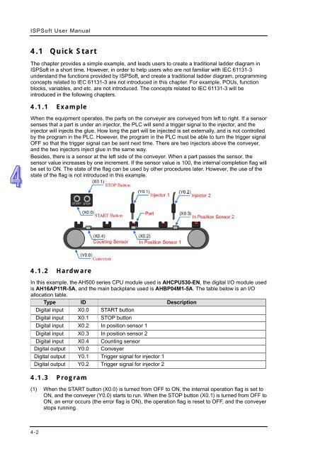
When the equipment operates, the parts on the conveyer are conveyed from left to right. If a sensor<br />
senses that a part is under an injector, the PLC will send a trigger signal to the injector, and the<br />
injector will injects the glue. How long the part will be injected is set externally, and is not controlled<br />
by the program in the PLC. However, the program in the PLC must be able to turn the trigger signal<br />
OFF so that the trigger signal can be sent next time. There are two injectors above the conveyer,<br />
and the two injectors inject glue in the same way.<br />
Besides, there is a sensor at the left side of the conveyer. When a part passes the sensor, the<br />
sensor value increases by one increment. If the sensor value is 100, the internal completion flag will<br />
be set to ON. The state of the flag can be used by other procedures later. However, the use of the<br />
state of the flag is not introduced in this example.<br />
4.1.2 Hardware<br />
In this example, the AH500 series CPU module used is AHCPU530-EN, the digital I/O module used<br />
is AH16AP11R-5A, and the main backplane used is AHBP04M1-5A. The table below is an I/O<br />
allocation table.<br />
Type ID Description<br />
Digital input X0.0 START button<br />
Digital input X0.1 STOP button<br />
Digital input X0.2 In position sensor 1<br />
Digital input X0.3 In position sensor 2<br />
Digital input X0.4 Counting sensor<br />
Digital output Y0.0 Conveyer<br />
Digital output Y0.1 Trigger signal for injector 1<br />
Digital output Y0.2 Trigger signal for injector 2<br />
4.1.3 Program<br />
(1) When the START button (X0.0) is turned from OFF to ON, the internal operation flag is set to<br />
ON, and the conveyer (Y0.0) starts to run. When the STOP button (X0.1) is turned from OFF to<br />
ON, an error occurs (the error flag is ON), the operation flag is reset to OFF, and the conveyer<br />
stops running.<br />
4-2


