AIRTRONIC D2/D4 Espar
AIRTRONIC D2/D4 Espar
AIRTRONIC D2/D4 Espar

You also want an ePaper? Increase the reach of your titles
YUMPU automatically turns print PDFs into web optimized ePapers that Google loves.
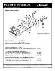
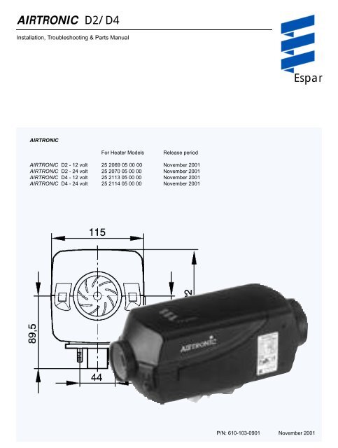
<strong>AIRTRONIC</strong> <strong>D2</strong>/<strong>D4</strong><br />
Installation, Troubleshooting & Parts Manual<br />
<strong>Espar</strong><br />
<strong>AIRTRONIC</strong><br />
For Heater Models<br />
Release period<br />
<strong>AIRTRONIC</strong> <strong>D2</strong> - 12 volt 25 2069 05 00 00 November 2001<br />
<strong>AIRTRONIC</strong> <strong>D2</strong> - 24 volt 25 2070 05 00 00 November 2001<br />
<strong>AIRTRONIC</strong> <strong>D4</strong> - 12 volt 25 2113 05 00 00 November 2001<br />
<strong>AIRTRONIC</strong> <strong>D4</strong> - 24 volt 25 2114 05 00 00 November 2001<br />
P/N: 610-103-0901 November 2001
Table of Contents<br />
Page<br />
Introduction Heater Warnings ........................................................ 3<br />
Introduction ........................................................ 4<br />
Specifications ........................................................ 5<br />
Principal Dimensions ........................................................ 6<br />
Heater Components ........................................................ 7<br />
Installation Procedures Heater Location ........................................................ 8<br />
Heater Mounting ........................................................ 8<br />
Heater Plate installation ........................................................ 8<br />
Mounting Pattern ........................................................ 9<br />
Ducting Components ........................................................ 9<br />
Heater Air Ducting ........................................................ 9<br />
Fuel System ........................................................ 10<br />
Electrical Connections ........................................................ 12<br />
Exhaust/Intake Connections ........................................................ 13<br />
Operating Switches ........................................................ 13<br />
Heater Operation Switch on ........................................................ 14<br />
Start-Up ........................................................ 14<br />
Temperature setting ........................................................ 14<br />
Temperature Control ........................................................ 15<br />
Switching Off ........................................................ 15<br />
Controls & Safety Equipment ........................................................ 15<br />
Operational Flow Chart ........................................................ 15<br />
Function Diagrams ........................................................ 16<br />
Schematic <strong>AIRTRONIC</strong> <strong>D2</strong>/<strong>D4</strong> ........................................................ 17<br />
Maintenance, Periodic Maintenance ........................................................ 18<br />
Troubleshooting & Basic Troubleshooting ........................................................ 18<br />
Repairs Self Diagnostic Troubleshooting ....................................................... 18<br />
Fuel Quantity Test ........................................................ 23<br />
Overheat/Flame sensor values ........................................................ 23<br />
Control and Resistance values ........................................................ 24<br />
Repair Steps ........................................................ 25<br />
Heater Parts <strong>AIRTRONIC</strong> <strong>D2</strong>/<strong>D4</strong> ........................................................ 30/32<br />
-Service Parts Diagram<br />
<strong>AIRTRONIC</strong> <strong>D2</strong>/<strong>D4</strong><br />
-Parts List ........................................................ 31/33<br />
Special Notes<br />
Note: Highlight areas requiring special attention or clarification.<br />
Caution: Indicates that personal injury or damage to equipment may occur unless specific guidelines are followed.<br />
Warning: Indicates that serious or fatal injury may result if specific guidelines are not followed.<br />
This publication was correct at the time of going to print. However, <strong>Espar</strong> Inc. has a policy of continuous improvement<br />
and reserves the right to amend any specifications without prior notice.
3<br />
Heater Warnings<br />
Warning To Installer:<br />
Correct installation of this heater is necessary to ensure<br />
safe and proper operation.<br />
Read and understand this manual before attempting to<br />
install a heater.<br />
Warning - Explosion Hazard<br />
1. Heater must be turned off while re-fueling.<br />
2. Do not install heater in enclosed areas where<br />
combustible fumes may be present.<br />
3. Do not install heaters in engine compartments of<br />
gasoline powered boats.<br />
Warning - Fire Hazard<br />
1. Install heater so it will maintain a minimum distance of<br />
2” from any flammable or heat sensitive material.<br />
2. Install the exhaust system so it will maintain a<br />
minimum distance of 2” from any flammable or heat<br />
sensitive material.<br />
3. Ensure that the fuel system is intact and there are no<br />
leaks.<br />
Failure to follow these instructions could cause fire resulting<br />
in serious or fatal injury.<br />
Warning - Asphyxiation Hazard<br />
1. Route the heater exhaust so that exhaust fumes can<br />
not enter any passenger compartments.<br />
2. Ensure an air tight seal will be maintained between<br />
the heater and mounting surface and at any exhaust<br />
connection points.<br />
3. Ensure that heating air supply is taken from an area<br />
where poisonous gases will not be present.<br />
4. If running exhaust components through an enclosed<br />
compartment, ensure that it is vented to the outside.<br />
Failure to follow these instructions could cause oxygen<br />
depletion resulting in serious or fatal injury.<br />
Direct questions to <strong>Espar</strong> Heater Systems<br />
ATTENTION<br />
Operation with bio-diesel<br />
<strong>AIRTRONIC</strong> <strong>D2</strong><br />
<strong>AIRTRONIC</strong> <strong>D2</strong> is not certified for use with bio-diesel.<br />
Admixtures of bio-diesel up to a magnitude of approx. 10%, as<br />
in some countries, are allowed.<br />
<strong>AIRTRONIC</strong> <strong>D4</strong><br />
<strong>AIRTRONIC</strong> <strong>D4</strong> is certified for operation with bio-diesel as per<br />
DIN V 51606 in free-flowing state when installed in “normal<br />
horizontal position (exhaust pipe downwards)”; bio-diesel is not<br />
permitted for any other installation positions.<br />
When using 100% bio-diesel, <strong>AIRTRONIC</strong> <strong>D4</strong> should be operated<br />
with pure diesel fuel twice per year, preferably in the middle<br />
and at the end of a winter period, to burn off any possible<br />
PME residues: For this purpose, drain your vehicle tank as far<br />
as possible (caution: do not forget to leave enough fuel in the<br />
tank to get to the next fuel station!) and then fill the tank with<br />
pure diesel fuel without bio-admixture.<br />
While using this tank filling, let <strong>AIRTRONIC</strong> <strong>D4</strong> run at the maximum<br />
temperatures pre-selection stage at least twice or three<br />
times for 30 minutes at a time. You can use this for example to<br />
pre-heat your vehicle before setting off. After this “diesel operation”<br />
of your <strong>AIRTRONIC</strong> <strong>D4</strong>, you can use bio-diesel again as<br />
required.<br />
When using mixtures of diesel / bio-diesel with up to 50% bioshare,<br />
it is not necessary to use pure diesel fuel now and then.<br />
ATTENTION<br />
Heating at high altitudes<br />
Up to 1500 meters - unrestricted heating operation is possible<br />
Above 1500 meters - heating operation is in principle possible<br />
for short periods, e.g. when crossing a mountain pass of during<br />
a brief stop. In cases of extended stays , the fuel supply at the<br />
fuel metering pump has to be adapted to high altitude conditions.<br />
Please call<br />
USA 1-800-387-4800<br />
CDA 1-800-668-5676<br />
for special circumstances.<br />
USA 1-800-387-4800<br />
CDA 1-800-668-5676
4<br />
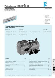
Introduction<br />
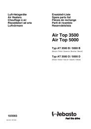
<strong>Espar</strong> ‘s <strong>AIRTRONIC</strong> bunk heaters<br />
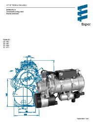
The <strong>AIRTRONIC</strong> <strong>D2</strong> is a compact diesel-fired 7,500 BTU/hr air<br />
heater, quality engineered to provide a dependable means of<br />
space heating. This heater is uniquely designed for inside<br />
mounting and ease of installation. The <strong>AIRTRONIC</strong> <strong>D4</strong> is a<br />
12,000 BTU/hr air heater for larger bunks.<br />
These heater provide hot air to the interior of vehicles<br />
for passenger comfort. Since the heater runs on diesel<br />
fuel and 12 or 24 volt power, it is able to provide space<br />
heat completely independently of the vehicle engine.<br />
The heater is operated by a rheostat switch or room thermostat.<br />
It cycles through four temperature settings (boost-highmedium-low)<br />
in order to maintain the desired temperature.<br />
If, in special cases, less heating capacity is required than<br />
the heater supplies in the “Low” setting, the heater switches to<br />
a “stand-by” setting. Temperature and overheat sensors, and a<br />
specially designed heat exchanger are among the safety features<br />
which make this heater a safe and dependable unit.<br />
For illustration purposes only
5<br />
Specifications<br />
<strong>AIRTRONIC</strong> <strong>D2</strong><br />
<strong>AIRTRONIC</strong> <strong>D4</strong><br />
Heat Output (±10%) 7,500 BTU/hr Boost (2.2 kW) 13,650 BTU/hr Boost (4.0 kW)<br />
6,150 BTU/hr High (1.8 kW) 10,200 BTU/hr High (3.0 kW)<br />
4,100 BTU/hr Medium (1.2 kW) 6,800 BTU/hr Medium (2.0 kW)<br />
2,900 BTU/hr Low (0.85 kW) 3,400 BTU/hr Low (1.0 kW)<br />
Current at 12v (±10%) 8.3 amps - Start 8.3 amps - Start<br />
2.8 amps - Boost 3.3 amps - Boost<br />
1.9 amps - High 2.0 amps - High<br />
1.0 amps - Medium 1.1 amps - Medium<br />
0.7 amps - Low 0.6 amps - Low<br />
Current at 24v (±10%) 4.2 amps/hr - Start 4.2 amps/hr - Start<br />
1.4 amps/hr - Boost 1.7 amps/hr - Boost<br />
1.0 amps/hr - High 1.0 amps/hr - High<br />
0.5 amps/hr - Medium 0.5 amps/hr - Medium<br />
0.3 amps/hr - Low 0.3 amps/hr - Low<br />
Fuel Consumption (±10%) U.S. Litre/hr U.S. Litre/hr<br />
Gal/hr<br />
Gal/hr<br />
Boost 0.07 0.28 Boost 0.13 0.51<br />
High 0.06 0.23 High 0.10 0.38<br />
Medium 0.04 0.14 Medium 0.07 0.25<br />
Low 0.03 0.10 Low 0.03 0.13<br />
Air Flow (±10%) 48 cfm Boost 85 cfm Boost<br />
40 cfm High 69 cfm High<br />
27 cfm Medium 50 cfm Medium<br />
19 cfm Low 30 cfm Low<br />
Operating Voltage Range 10.5 - 16 vdc at 12 vdc 10.5 - 16 vdc at 12 vdc<br />
21 - 32 vdc at 24 vdc 21 - 32 vdc at 24 vdc<br />
Overheat Temperature 240°F (115°C) 240°F (116°C)<br />
Shutdown (±10%)<br />
Ambient Operating -40°F to 158°F (-40°C to 70°C) -40°F to 158°F (-40°C to 70°C)<br />
Temperature<br />
Weight 6.0 lbs. (2.7 kg) 9.9 lbs. (4.5 kg)<br />
Note: The heater control unit is equipped with a low<br />
voltage cutout to prevent vehicle battery drain and<br />
a high voltage cutout to protect heater electrical<br />
parts.
6<br />
* All measurements in millimeters<br />
25.4 mm = 1”<br />
Principal Dimensions <strong>AIRTRONIC</strong> <strong>D2</strong><br />
Minimum installation distance<br />
(clearance) to open the lid and to<br />
dismount the glow pin and the<br />
control unit.<br />
Minimum installation distance<br />
(clearance) to take in heating air.<br />
(12.2 inches)<br />
(4.5 inches)<br />
Principal Dimensions <strong>AIRTRONIC</strong> <strong>D4</strong><br />
(14.8 inches)<br />
(5.5 inches)
7<br />
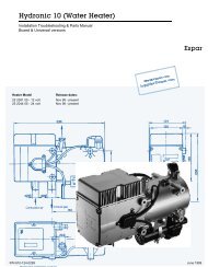
Heater Components<br />
1 Hot Air Blower Wheel<br />
2 Control Unit<br />
3 Combustion Air Blower Wheel<br />
4 Glow Pin<br />
5 Cover<br />
6 Heat Exchanger<br />
7 Overheat/Flame sensor<br />
8 7 Day Timer with thermostat (optional)<br />
9 Operating Unit (Thermostat)<br />
10 Operating Unit (Rheostat)<br />
11 Blower Motor<br />
12 Fuel Connection<br />
13 Flange Seal<br />
14 Combustion Chamber<br />
15 Hot Air Outlet Hood<br />
16 Combustion Air Intake Hose<br />
17 Fuel Metering Pump<br />
18 Fuel Filter built into FMP<br />
19 Hot Air Output Deflector<br />
20 Flexible Exhaust Pipe<br />
21 Main Fuse: -<br />
<strong>AIRTRONIC</strong> <strong>D2</strong> - 20 A<br />
<strong>AIRTRONIC</strong> <strong>D4</strong> - 10 A<br />
C = Combustion Air<br />
D = Fuel Intake from tank<br />
E = Exhaust<br />
F = Fresh Air Intake<br />
H = Hot Air Output
8<br />
Installation Procedures<br />
Heater Mounting Plate Installation<br />
Heater Location<br />
Depending on the type of vehicle, the best location for mounting<br />
the heater will vary. Typically, air heaters are mounted<br />
inside tool or luggage compartments. However, the heater may<br />
be mounted anywhere inside the vehicle provided you adhere<br />
to the following conditions:<br />
• Combustion air intake, exhaust and fuel inlet must be<br />
located outside of the vehicle.<br />
• Heater must be mounted on flat horizontal surface<br />
providing an air tight seal between heater and vehicle.<br />
• Do not mount the heater outside the vehicle, unless care is<br />
taken to protect the heater from the weather. When selecting<br />
the location, consider the following:<br />
• Combustion air and exhaust connections.<br />
• Ducting.<br />
• Fuel line connections.<br />
• Electrical connections.<br />
Hex Head Tek Screw<br />
Flat washer<br />
Nut<br />
Spring Washer<br />
Cab Floor<br />
Silicon gasket (flange)<br />
Stainless Steel Plate<br />
Plate seal<br />
Note: Tighten screws sufficiently to ensure positive seal<br />
between mounting plate and mounting surface.<br />
Do not over tighten.<br />
Heater Mounting<br />
A mounting plate and hardware are provided with the truck<br />
heater kit.<br />
• Choose heater location.<br />
• Using template provided, drill and cut center hole. Cut (1)<br />
four and one half inch (4 1/2”) diameter hole or one rectangular<br />
hole four (4”) by five (5”) inches to accommodate<br />
mounting plate and seal. Secure mounting plate to vehicle<br />
floor with “Tek” screws provided.<br />
• Use Heater flange as a template if not using mounting plate<br />
and seal<br />
• Mount heater on mounting plate with nuts and spring<br />
washers provided.<br />
• For ease of installation make the exhaust, combustion air<br />
intake and fuel connections at base of heater before mounting<br />
the heater into the vehicle. See following pages for<br />
instructions and restrictions on exhaust, combustion and fuel<br />
hook-ups.<br />
Wiring Harness<br />
Right or Left<br />
Stainless Steel<br />
Mounting Plate<br />
and seal<br />
Heater<br />
Flange<br />
Wiring harness connection, right or left<br />
Exhaust<br />
Tubing<br />
Wiring harness can be converted to the opposite side of the<br />
heater if it makes the installation more practical. To do this you<br />
must remove the <strong>AIRTRONIC</strong> cover and then the control unit.<br />
On the control unit (underneath) is a semicircular clip protecting<br />
the harness. This must be removed. The harness should be<br />
moved to the other side of the control unit then reassembled.<br />
The grommet on the heater casing (side) must also be taken<br />
out and secured into the opposite lower side of heater casing.<br />
Combustion<br />
Air intake<br />
Fuel line
9<br />
Mounting Pattern<br />
inches<br />
millimeters<br />
Heater Air Ducting Installation<br />
A 60mm flexible duct 40 inches long, hot air outlet and clamps<br />
are provided with the heater kit. In routing and installing the<br />
ducting the following criteria must be observed:<br />
• Route ducting with smooth bends. Avoid crushing duct.<br />
• Position hot air outlet so that it cannot be obstructed.<br />
• When not using return ducting. Use a protective air intake<br />
grille on air inlet side of heater to prevent objects from<br />
being sucked in.<br />
• Ensure provisions are made for proper air return ventilation.<br />
• Use return air ducting for best heating efficiency.<br />
For illustration<br />
purposes only<br />
Return Ducting<br />
No Return Ducting<br />
Ducting Components<br />
For illustration<br />
purposes only<br />
1. Protective Grill 5. Air Outlet - Rotatable<br />
2. Air Outlet Hood <strong>AIRTRONIC</strong> <strong>D2</strong> - ø60 or75mm 6. Connection Piece<br />
<strong>AIRTRONIC</strong> <strong>D4</strong> - ø75 or 90mm<br />
7. Protective Grill<br />
3. Hose Clamp 2-2 3/4” 8. 90° Bend Ducting 2 3/8”<br />
4. Flex Duct 2 3/8” (ø60 or 75mm) (ø90mm on <strong>D4</strong>)<br />
Warning: Do not use existing vehicle ducting or outlets.<br />
Ducts and outlets must be capable of withstanding<br />
a minimum of 300°F operating temperatures.<br />
Caution:<br />
Do not over tighten duct clamps.<br />
Do not position outlet so that it will blow hot air<br />
directly at operator or at room thermostat.
10<br />
Fuel System<br />
The fuel metering pump is the heart of the system and must be<br />
installed properly to ensure a successful heater operation.<br />
Fuel System Overview<br />
7<br />
6<br />
Max. 6’6”<br />
Max. 20’<br />
6<br />
7<br />
8<br />
Max. 6’6”<br />
2<br />
3<br />
5<br />
Max. 2’6”<br />
2<br />
3<br />
4<br />
Max. 2’<br />
9<br />
3<br />
5<br />
Fuel<br />
Tank<br />
1<br />
Fuel<br />
Tank<br />
1<br />
3<br />
Optional<br />
Note: Butt joints and clamps on all connections.<br />
1. Fuel Pick-Up Pipe<br />
2. 5.0 Rubber Connector<br />
3. 11mm Clamp<br />
4. 2.0mm Black Plastic Fuel Line<br />
5. Fuel Metering Pump<br />
6. 9mm Clamp<br />
7. 3.5mm Rubber Connector<br />
8. 1.5mm White Plastic Fuel Line<br />
9. 5mm Rubber Fuel Line<br />
Fuel Pick-Up Pipe Installation (Standard Pick-Up)<br />
• Choose a protected mounting location close to the fuel<br />
pump and heater. A spare fuel sender gauge plate provides<br />
an ideal mounting location.<br />
• Drill the mounting holes as shown<br />
• Cut the fuel pick-up pipe to length.<br />
• Mount the fuel pick-up pipe as shown.<br />
• Lower the fuel pick-up pipe (with reinforcing washer) into<br />
the tank using the slot created by the two 1/4” holes.<br />
• Lift the assembly into position through the 1” hole.<br />
• Assemble the rubber washer, metal cup washer and nut.<br />
Note: Drill the two 1/4” holes first.<br />
Optional
11<br />
NPT fitting and pipe<br />
optional<br />
Custom Pick-Up Pipe with NPT fitting - optional<br />
• Remove an existing plug from the top of the fuel tank.<br />
• Cut the fuel pick-up pipe to length.<br />
• Secure the fuel pick-up pipe into position using the<br />
combined NPT compression fitting<br />
Note: NPT fittings are available in various sizes (Refer<br />
to parts section).<br />
Fuel Metering Pump<br />
• Choose a protected mounting location close to the fuel<br />
pick-up pipe and heater if not using standard assembly as<br />
shown on right.<br />
• Using the bracket and rubber mount provided, install fuel<br />
pump as shown<br />
Typical standard assembly, if<br />
not using this format please<br />
adhere to specifications on<br />
pg.10<br />
Note: Proper mounting angle of the fuel pump is<br />
necessary to allow any air or vapor in the fuel<br />
lines to pass through the pump rather than cause<br />
a blockage.<br />
Fuel Line<br />
• Route fuel lines from the fuel pick-up pipe to the fuel<br />
metering pump then to the heater.<br />
• Use fuel lines provided.<br />
• Other sizes or types of fuel lines may inhibit proper<br />
fuel flow.<br />
• Make proper butt joints using clamps and connector<br />
pieces as shown on previous page<br />
• Use a sharp utility knife to cut plastic<br />
fuel lines to avoid burrs and pinching<br />
fuel line shut.
12<br />
Electrical Connections<br />
Main Harness.......................................................................<br />
Power Harness.....................................................................<br />
Switch Harness....................................................................<br />
Fuel Metering Pump Harness.............................................<br />
Diagnostic Harness.............................................................<br />
16 pin connector with 10 terminated wires at 8 terminals.<br />
(green/red, blue/white (2), red, grey/red, grey, brown,<br />
brown/white and yellow (2)).<br />
Connect to the heater ’s 16 pin connector<br />
Connect other harnesses as described below<br />
2 core harness (red and brown).<br />
Route power harness to batteries, cut to length and terminate<br />
as described below. Install 20 amp fuse last. (10 amp on 24V).<br />
Connect red wire to fuse holder near battery.<br />
Connect fuse link wire directly to battery positive post using<br />
ring terminal.<br />
Connect brown wire directly to battery negative post using ring<br />
terminal.<br />
7 core harness (red, brown/white, yellow, grey, brown, grey/red and<br />
b l u e / w h i t e )<br />
Route this harness the length required to reach thermostat<br />
installed in bunk compartment. Do not cut this harness, wires have<br />
been soldered at ends for convenience of terminating to terminals<br />
on thermostat. Coil up excess harness and secure in safe location.<br />
Connect to thermostat or rheostat switch (refer to switch connection<br />
section).<br />
2 core harness (green/red and brown).<br />
Route this harness from heater to fuel metering pump. Cut to<br />
length and connect to fuel metering pump using single terminals<br />
and connector provided with kit. (no polarity required).<br />
4 pin on 8 pin connector.(red, brown, yellow, blue/white<br />
For diagnostic purposes only.<br />
Caution: Install power 20 amp fuse only after all electrical<br />
connections are complete. 10 amp on 24V.<br />
Note: All exposed electrical connections should be coated<br />
with protective grease, (petroleum gel,<br />
Vaseline, etc.).<br />
Main Harness<br />
Fuel Metering Pump Harness<br />
Connector for Diagnostics<br />
Fuse and holder<br />
Switch Harness<br />
Thermostat<br />
Power Harness
13<br />
Exhaust and Combustion Air Intake Connections<br />
A 24mm flexible stainless steel exhaust pipe (39”long) and a<br />
25mm flexible plastic tube (39” long) for combustion air intake<br />
are included with the heater kit. Exhaust clamps and holders<br />
are also provided.<br />
Caution:<br />
Route exhaust and combustion air intakes so they<br />
cannot be plugged by dirt, water or snow.Ensure the<br />
outlets do not face into the vehicle slip stream.<br />
Keep exhaust and combustion air intake a minimum<br />
of 12” apart.<br />
Drill 1/8” holes in exhaust pipe if necessary to allow<br />
water drainage.<br />
Combustion air intake and exhaust lengths can be<br />
shortened to a minimum of 8”.<br />
• Attach the exhaust pipe to the exhaust outlet of the heat<br />
exchanger<br />
• Route exhaust pipe to an open area to the rear or side of<br />
the vehicle so that fumes cannot build up and enter the<br />
cab or the combustion air inlet to the heater.<br />
• Install protective cap.<br />
• Attach the combustion air intake tube to the combustion<br />
air inlet of the heater<br />
• Once secure to the heater inlet, the intake pipe must be<br />
routed to the underside of the vehicle where it will pick up<br />
clean, fresh, moisture free air.<br />
Operating Switches<br />
The heater can be controlled using a Thermostat or Rheostat<br />
type switch. It can also be controlled by a 7 day timer with thermostat.<br />
See schematic pg. 17.<br />
Thermostat<br />
• Select a mounting location which will be representative of<br />
the average temperature of the area being heated. Avoid<br />
mounting near heater outlets, windows, doors, electrical<br />
appliances or in areas receiving direct sunlight.<br />
• Route the switch harness from the heater to the thermostat<br />
mounting location.<br />
• Mount the thermostat as shown using proper mounting<br />
hardware and the slots provided on the thermostat base.<br />
Pull the switch harness through the<br />
thermostat base access hole.<br />
• Connect the six core switch harness to the thermostat as<br />
shown<br />
Mounting slots<br />
Thermostat base<br />
access hole<br />
Combustion Air Intake<br />
( min. 8” - max. 6.5’).<br />
Exhaust ( min. 8” - max. 6.5’).<br />
End Cap<br />
End Cap<br />
Warning: The exhaust is hot, keep a minimum of 2”<br />
clearance from any heat sensitive material<br />
This wire is “optional”<br />
• It is recommended that when using return ducting, not to<br />
use this wire. See illustration on pg. 9 for ducting.<br />
• Not using the grey wire defaults the heater to use the temperature<br />
sensor on the control unit of the heater.<br />
• Use of the grey wire defaults the heater to use the sensor<br />
on the thermostat.<br />
• The sensor on the control unit provides a more accurate<br />
reading of the overall air temperature, whereas the sensor<br />
in the thermostat gives more of a spot reading of the air<br />
surrounding the thermostat.<br />
Temperature sensor on<br />
<strong>AIRTRONIC</strong> control unit.<br />
Warning:<br />
Route exhaust so that the exhaust fumes<br />
cannot enter the passenger compartment.
14<br />
Rheostat Switch<br />
Note: When using Rheostat switch, the Return Ducting<br />
method must be used as shown on page 9. This<br />
allows the <strong>AIRTRONIC</strong> heater’s internal sensor to<br />
properly monitor cab temperature.<br />
• Mount the rheostat switch in a location<br />
where it is easily accessible.<br />
• Route the switch harness from the<br />
heater to the Rheostat mounting location.<br />
• Connect the six core switch harness<br />
as shown<br />
Temperature sensor on<br />
<strong>AIRTRONIC</strong> control unit.<br />
Heater Operation<br />
Warning: To prevent fire, the heater must be switched<br />
off while filling fuel tanks.<br />
To prevent asphyxiation, the heater must not<br />
be operated in enclosed areas unless heat<br />
exhaust is routed to outside of garage bay.<br />
1 Switch On<br />
• Switch the heater on using the room thermostat’s, On/Off<br />
switch (1=On, 0=Off ) or the rheostat switch.<br />
2 Start Up<br />
On start up the indicator light illuminates and the following<br />
sequences take place:<br />
3 Temperature Setting<br />
Using the adjusting dial, set the desired temperature range.<br />
• Lowest Setting - approx. 10°C (50˚F)<br />
• Mid - Setting - approx. 20°C (68˚F)<br />
• Highest Setting - approx. 30°C (86˚F)<br />
On/Off switch<br />
Green diagnostic light<br />
Red operating light<br />
• Control unit does a systems check of the glow pin, flame<br />
sensor/temperature sensor, fuel metering pump and control<br />
unit.<br />
• Blower starts slowly and begins to accelerate.<br />
• Glow pin is energized and starts preheating the combustion<br />
chamber.<br />
• After a delay (approx. 60 seconds) the fuel pump delivers<br />
fuel.<br />
• Ignition will take place as the fuel/air mixture contact the<br />
glow pin.<br />
• Blower speed and fuel delivery are slowly increased.<br />
• Once flame sensor has detected a flame the glow pin will<br />
switch off, after approx. 60 secs.<br />
• After another 120 secs., heater will have reached maximum<br />
power.<br />
On OEM installs the ‘red” & “green” indicator lights illuminate.<br />
On after market installs only the “Red” light illuminates.<br />
High<br />
Operation indicating light<br />
Low
15<br />
4. Temperature Control<br />
• The temperature is monitored constantly at the heater’s<br />
process air inlet or thermostat.<br />
• This temperature is compared to the set temperature on<br />
the adjusting dial.<br />
• The heater cycles through Boost, High, Medium and Low<br />
heat modes to maintain the desired temperature.<br />
• If the desired temperature is exceeded while the heater is<br />
operating in low heat mode the heater will switch into<br />
“standby” mode. This is a comfort feature.<br />
• The heater will re-start in once heat is again required.<br />
5 Switch Off<br />
Once switched off either manually or automatically, the heater<br />
begins a controlled cool down cycle.<br />
• Indicating light(s) on switch will go off<br />
• Fuel pump stops delivering fuel.<br />
• The glow pin is re-energized for a 40 second after-glow to<br />
burn off any combustion residue.<br />
• The blower continues to run for 4 minutes and automatically<br />
switches off.<br />
6 Controls and Safety Equipment<br />
• If the heater fails to ignite within two 90 second start<br />
attempts, a "no start" shut down occurs.<br />
• If a flame out occurs after the heater has started, the<br />
heater will attempt to restart.<br />
• If repeated flame outs occur within 15 minutes the heater<br />
will not restart.<br />
• Overheat shut down will occur if there is a restriction of the<br />
heating air flow (i.e. blocked inlet or outlet). The overheat<br />
sensor will automatically reset once the heater has cooled<br />
down.<br />
• Once the air flow restriction is removed, the heater can be<br />
re-started by switching the heater off then back on.<br />
• If the voltage drops below 10.5 volts or rises above 16<br />
volts the heater will shut down (21 volts and 28 volts for 24<br />
volt systems).<br />
• If the glow pin circuit or fuel metering pump circuit are<br />
interrupted the heater will not start.<br />
• The blower motor is checked on start<br />
up and continuously during operation.<br />
Shut down will occur if the blower does<br />
not start or maintain proper speed.<br />
Operational Flow Chart
16<br />
Function diagram <strong>AIRTRONIC</strong> <strong>D2</strong><br />
Function diagram <strong>AIRTRONIC</strong> <strong>D4</strong>
17<br />
Schematic <strong>AIRTRONIC</strong> <strong>D2</strong> / <strong>AIRTRONIC</strong> <strong>D4</strong><br />
Wire color key<br />
for switches<br />
Designation<br />
red = power (+)<br />
yellow = switch<br />
brown = ground (-)<br />
grey = temperature sensor<br />
on thermostat<br />
*vehicle dimmer switch<br />
for light display on<br />
7-day timer<br />
grey/red = temperature setting<br />
blue = diagnostic<br />
from heater<br />
blue/white = diagnostic<br />
from heater<br />
brown/white = ground<br />
black = to vehicle ignition<br />
accessories for continuous<br />
operation of heater<br />
1.1 Blower Motor<br />
1.2 Glow Pin<br />
1.5 Overheat and Flame sensor<br />
2.1 Control Unit<br />
2.2 Fuel Metering Pump<br />
2.7 Main Fuse 12Volt - 20 amp / 24 volt - 10 amp<br />
3.1.11 Rheostat<br />
3.2.8 7 Day Timer<br />
3.5 Thermostat<br />
5.1 Battery<br />
6.1 Diagnostic Pigtail (for connection to Fault code retrieval device)
18<br />
Maintenance<br />
Recommended Periodic Maintenance<br />
• Remove the glow pin and inspect for carbon build up.<br />
Clean or replace.<br />
• Remove the glow pin screen and inspect for carbon build<br />
up. Clean or replace.<br />
• Make sure vent hole is open. <strong>Espar</strong> recommends the use<br />
of non detergent 100% volatile carburetor cleaner, an air<br />
gun will also help. Remove loose carbon from the glow pin<br />
chamber.<br />
• Inspect the ducting, the air intake screen and air outlet for<br />
restriction or blockage.<br />
• Inspect combustion air intake and exhaust for blockage.<br />
• Operate your heater for a minimum of 20 minutes each<br />
month<br />
• Maintain your batteries and all electrical connections in<br />
good condition. With insufficient power the heater will not<br />
start. Low and high voltage cutouts will shut the heater<br />
down automatically.<br />
• Use fuel suitable for the climate (see engine manufacturers<br />
recommendations). Blending used engine oil with<br />
diesel fuel is not permitted.<br />
Basic Troubleshooting<br />
Check LIst:<br />
What happens when the heater is switched on and ....<br />
Heater does not ignite<br />
1 Blower motor does not run<br />
Check:<br />
- Fuse in power harness.<br />
- Power to control unit.<br />
- Power to and from switch.<br />
- Electrical connections.<br />
2 Blower motor runs approximately 20 seconds and then<br />
shuts off<br />
Check:<br />
- Ensure voltage at control unit remains<br />
above 10 volts during start up with glow<br />
plug circuit on.<br />
3 Blower motor runs/fuel metering pump starts and then<br />
shuts down after two start up attempts<br />
Check:<br />
- Fuel lines and fuel filter.<br />
- Fuel quantity. Pg. 23<br />
- Combustion air or exhaust tube blockage.<br />
4 Blower motor runs/ no fuel metering pump<br />
Check:<br />
- For electrical pulses at fuel metering<br />
pump.<br />
- If pump is frozen.<br />
- Blocked fuel line.<br />
Heater ignites<br />
1 Shuts down at random<br />
Check: - Fuel metering pump quantity. Pg. 23<br />
- Possible overheat.<br />
- Control unit input voltage.<br />
2 Heater smokes and carbons up<br />
Check:<br />
- Exhaust pipe blocked.<br />
- Combustion air intake blocked.<br />
- Exhaust entering combustion air intake<br />
pipe.<br />
- Short cycling, rapid on/off operation.<br />
- Fuel system.<br />
- Fuel metering pump quantity.<br />
- Motor rpm.
19<br />
Self Diagnostics<br />
The heater is equipped with self diagnostic capability. To<br />
retrieve information on the heater ’s last 5 faults, a retrieval<br />
device is required (part # CA1 05 020). There is a pig tail to<br />
accommodate the connector on the main harness from<br />
heater. If wire pigtail is not present, a wiring<br />
adapter (P/N: 22 1000 31 86 00) must be used.<br />
Connect the fault code retrieval device as shown. This device<br />
enables these four functions to be performed.<br />
1. Access the current fault which is affecting the heater<br />
2. Access the four previous faults which affected the heater.<br />
3. Clear the fault memory to erase previous fault history<br />
4. Unlock “lockout features” which exist for some control<br />
units.<br />
Equipment Face and Controls<br />
Symbols that are seen on the display face are as follows:<br />
AF<br />
F1-F5<br />
DIAG<br />
Actual fault.<br />
Up to five stored faults can be accessed.<br />
The AF and F1 are the same number.<br />
This sign is displayed when the heater is in<br />
operation.<br />
The word (DIAG) nostic will come on when<br />
the diagnostic number is requested.<br />
On/Off<br />
Retrieval Device<br />
000 Three digit diagnostic fault code number.<br />
On/Off switch<br />
• Switch the fault code retrieval device on and wait 10<br />
seconds.<br />
• Press the "D" button.<br />
• Wait 3-5 seconds for the current fault code to appear (AF).<br />
• To review the previous faults use the arrow buttons<br />
(F1= Most Recent, F5= Oldest).<br />
• Consult the fault code chart for code number descriptions.<br />
• To erase the faults that are in memory press both "L" keys<br />
at the same time for 5 seconds. This will also a unlock the<br />
control unit.
20<br />
Note:<br />
If there are no heater faults, the heater will go through<br />
a normal start cycle and regulate based on thermostat<br />
setting.<br />
See schematic<br />
pg. 17<br />
Fault Code<br />
Fault Description Causes / Repair<br />
000 Normal Operation<br />
004 Warning - short circuit in controller, fresh air-outlet Disconnect connection S1/B1 at <strong>AIRTRONIC</strong>. At connector B1, pin 16<br />
check for short between pin and blower relay. If no short exists replace<br />
control unit.<br />
005 Warning - short circuit at controller - anti-theft alarm output Disconnect connection S1/B1 at <strong>AIRTRONIC</strong>. At connector B1, pin 16<br />
check the line through to the relay isolating switch or theft warning in<br />
line for short circuit to chassis. If no short exists replace control unit.<br />
009 TRS - shut down Switch off due to signal change.Check for change of signal from (+) to<br />
(-) at pin 13 (S1) or a (+) signal at pin 14 (S1).<br />
010 Overvoltage Start vehicle motor. Check voltage at (B1) between terminals 1 and 10.<br />
This must be less than 16 volts (15.2 volts with glow plug on). Check<br />
vehicle charging system.<br />
<strong>AIRTRONIC</strong> 24 volt - voltage must be less than 32 volts<br />
011 Undervoltage shut down Start vehicle motor. Check voltage at connector (B1) between terminals<br />
1 and 10. This must be more than 10 volts. Check vehicle charging<br />
system. Check batteries and connections.<br />
<strong>AIRTRONIC</strong> 24 volt - voltage must be more than 21 volts.<br />
012 Overheat at overheating sensor Sensor has detected excessive temperatures. Check for clogged hot air<br />
ducting. Check that the the total number of ducting pieces in unison is<br />
not too large. Re-route if necessary. Check overheat sensor resistance<br />
values. (see component value chart pg 23). If O.K. Measure fuel quantity.<br />
See page 23.<br />
013 Overheat at flame sensor Flame sensor detects excessive temperature at heat exchanger. Check<br />
for clogged hot air ducting. Check that the the total number of ducting<br />
pieces in unison is not too large. Re-route if necessary. Measure fuel<br />
quantity. See page 22. Check flame sensor resistance. (see component<br />
value chart pg 22)<br />
014 Temperature difference between flame sensor and Check for clogged hot air ducting. Check that the the total number of<br />
overheating sensor too large<br />
ducting pieces in unison is not too large. Check flame sensor, if O.K.,<br />
check overheating sensor. If over-heating sensor defective replace<br />
combi-sensor. If over-heating sensor O.K. measure fuel quantity. See<br />
page 23. If fuel quantity O.K. replace control unit.<br />
015 Overheat with excessive temperatures Fault code 015 is shown when the <strong>AIRTRONIC</strong> is switched on again<br />
after fault code 017. The hardware limit value for the overheating sensor,<br />
has been exceeded - control unit is damaged. Check sensor.<br />
Replace control unit.<br />
017 Overheat with excessive temperature The hardware limit value for the overheating sensor, has been exceeded,<br />
because the control unit has not detected fault code 012, 013.The<br />
control unit is locked. If <strong>AIRTRONIC</strong> is switched on again, fault code<br />
015 is displayed. Replace control unit. Check sensor.<br />
020 Open circuit - glow pin Check continuity of glow pin.<br />
<strong>AIRTRONIC</strong> 12 volt - approx. 0.5 Ω ± 0.05 Ω<br />
<strong>AIRTRONIC</strong> 24 volt - approx. 2 Ω ± 0.2 Ω<br />
021 Short circuit - glow pin<br />
Caution!<br />
Check functions of glow pin in installed condition, to do so disconnect<br />
connector from controller. <strong>AIRTRONIC</strong> 12 Volt and 24 Volt. Apply voltage<br />
of 8 / 18 volts to glow pin respectively, and measure current<br />
For <strong>AIRTRONIC</strong> 12 volt, check functions with max. 8 volt<br />
intensity after 40 seconds. Glow in is O.K. for the following values:<br />
For <strong>AIRTRONIC</strong> 24 volt, check functions with max. 18 volt.<br />
glow pin 8 volt - current = 9 amps + 1.5 / - 1.2 amps<br />
if voltage values are exceeded the component is destroyed.<br />
glow pin 18 volt - current = 4 amps ± 0.5 amps<br />
Check sort-circuit resistance of mains unit: min. 20 Amp. If the values differ, replace glow pin. If the values of the continuity test<br />
and function test are O.K., check glow pin cable harness for damage<br />
and continuity. If O.K., replace control unit.
21<br />
Fault Code<br />
Fault Description Causes / Repair<br />
031 Blower motor interrupted Check blower motor cable harness for correct routing and damage. If<br />
O.K., disconnect cable harness from control unit and check for continuity,<br />
if O.K., replace control unit.<br />
032 Blower motor, short circuit Check functions of blower motor, to so so, disconnect connector from<br />
control unit. Apply voltage of 8 volts or 18 volts ± 0.1 to blower motor<br />
Caution!<br />
and measure current intensity after 40 seconds.<br />
For <strong>AIRTRONIC</strong> 12 volt, check functions with max. 8 volt<br />
Current < 6.5 amp - blower motor O.K., replace controller<br />
For <strong>AIRTRONIC</strong> 24 volt, check functions with max. 18 volt.<br />
Current > 6.5 amp, replace blower.<br />
if voltage values are exceeded the component is destroyed.<br />
Check sort-circuit resistance of mains unit: min. 20 Amp.<br />
033 Blower motor does not turn Motor speed varies from specification by more than 10% for longer than<br />
30 seconds.<br />
If too slow, check for restriction, and check for short in motor circuit or<br />
control unit. If none found, replace blower.<br />
If too fast, check for damage or missing magnetic sensor on control<br />
unit. Replace blower motor if damaged.<br />
Replace control unit otherwise.<br />
047 Short circuit - fuel metering pump Disconnect connector from fuel metering pump, if fault code 048 (interruption)<br />
is displayed then the fuel metering pump is defective, replace<br />
FMP.<br />
If fault code 047 is still displayed, then disconnect connection S1/B1. At<br />
connector B1, Pin 5, check line1(green/red) through to FMP for short<br />
circuit to (pin 10), if O.K. replace control unit<br />
048 Open circuit - fuel metering pump Disconnect connector from fuel pump and measure resistance value of<br />
fuel pump (see values, pg 22). If resistance values O.K., then reconnect<br />
cable harness to the fuel pump. Disconnect connection S1/B1,<br />
and measure the resistance value between pin 5 and pin 10. If O.K.,<br />
replace control unit.<br />
050 Too many no start attempts Control unit is locked after too many unsuccessful start attempts. Check<br />
fuel, glow plug, combustion air and exhaust flow. Use control unit<br />
tester or fault code retrieval device to unlock control unit. Maximum 255<br />
051 Faulty flame recognition If the resistance value of flame sensor is 1274 Ω after switching on (><br />
70°C), then the blower of the <strong>AIRTRONIC</strong> runs for approx. 15 minutes<br />
to cool down. If resistance does not fall below the above value within<br />
15 mins.., this is followed by fault shut down. Check flame sensor, diagrams<br />
and values, pg 23. If O.K., replace control unit.<br />
052 No start safety time exceeded No flame detected on start attempt.Check exhaust and combustion air<br />
lines. Check fuel supply/measure fuel quantity, see following pages.<br />
Check glow pin (see fault code 020 and 021). Check flame sensor, diagram<br />
and values table on following pages, if O.K., replace control unit.<br />
053 Flame cutout in boost mode Heater has started successfully the flame has extinguished.<br />
054 Flame cutout in high mode Check exhaust and combustion air lines. Check fuel<br />
055 Flame cutout in medium mode supply/measure fuel quantity, see values, pg 23. Check flame<br />
056 Flame cutout in low mode sensor, diagram and values table on following pages, if O.K., replace<br />
control unit.<br />
060 Open circuit - external temperature Temperature sensor detects a value beyond it's range sensor<br />
Disconnect connection S1/B1 (main harness), measure resistance<br />
value at connector B1, pins 6 & 12. Refer to the values table on pg 23.<br />
If there is an open circuit, the ohmic value between the pins is > 7175<br />
Ω. If the resistance value is O.K., then the control unit is defective.<br />
061 Short circuit - external temperature Disconnect connection S1/B1 (main harness), measure resistance<br />
value at connector B1, between pins 6 & 12., see values on pg 23. If<br />
there is a short circuit, the ohmic value between the pins is < 486 Ω. If<br />
fault 061 continues to be displayed, then the control unit is defective.
22<br />
Fault Code<br />
Fault Description Causes / Repair<br />
062 Thermostat/Rheostat/Timer, open circuit Potentiometer values outside of range on Thermostat (switch)<br />
Check resistance between pins 6 and 7 at B1.<br />
Resistance value for interruption between pins > 7175 Ω<br />
Normal value: 1740 Ω - 2180 Ω (± 80 Ω )<br />
If resistance value is O.K., replace control unit. If not replace thermostat/(switch).<br />
063 Switch control - short circuit<br />
Fault recognition only works in heating mode. However, if<br />
a short circuit already exists and the <strong>AIRTRONIC</strong> is subsequently<br />
switched on, ventilating mode will be active (no<br />
fault code).<br />
If a ventilating switch has been built in, disconnect and check function.<br />
If faulty, replace switch. Disconnect wires from thermostat or switch. If<br />
fault code 062 is displayed, replace switch. If switch is O.K., check connection<br />
lines grey/red and brown/white for short-circuit. If O.K., reconnect<br />
wires to thermostat/switch. Disconnect connection B1. If fault 063<br />
is still displayed, replace control unit. Resistance value for short circuit<br />
between pins 6 and 7 < 486 Ω. Normal value: 1740 Ω - 2180 Ω (± 80<br />
Ω).<br />
064 Open circuit - flame sensor Sensor is sensing value outside of range. Open Airtronic shell and<br />
remove control unit from casing. Disconnect green connector from control<br />
unit. At green connector measure resistance value at green wire<br />
and brown/white wire. Check flame sensor, diagram and values on pg.<br />
23. If flame sensor is O.K., replace control unit. Resistance value for<br />
interruption > 7175 Ω<br />
065 Short circuit - flame sensor Open Airtronic shell and remove control unit from casing. Disconnect<br />
green connector from control unit. If fault 064 is displayed, replace<br />
combination sensor (flame/temperature). If fault 065 is still displayed,<br />
replace control unit. Resistance value for shot circuit < 486 Ω, see values<br />
on following pages.<br />
071 Open circuit - overheat sensor Open Airtronic shell and remove control unit from casing. Disconnect<br />
blue and green connectors from control unit. Measure the resistance<br />
value at blue connector(pin 1- blue wire) and at green connector pin 2<br />
(brown/white wire). See values on following pages. If O.K., replace control<br />
unit. Resistance value for interruption > 223 Ω.<br />
072 Short circuit - overheat sensor Open Airtronic shell and remove control unit from casing. Disconnect<br />
blue connector from control unit. If fault 071 displayed, replace combination<br />
sensor (flame/temperature). If fault 072 is still displayed, replace<br />
control unit. Resistance value for short circuit < 183 Ω, see following<br />
pages for values.<br />
090 Control unit defect Internal failure. Replace control unit.<br />
091 External voltage disturbance Check vehicle charging system. Poor battery, battery charger, eliminate<br />
fault.<br />
092 Control unit defective (ROM fault) Internal failure. Replace control unit.<br />
094 Control unit defective (EEPROM fault) Replace control unit<br />
096 Internal temperature sensor defect Replace control unit or use external temperature sensor.<br />
097 Control unit defective (power failure) Internal failure. Replace control unit.
23<br />
Fuel Quantity Test<br />
Values for Overheat sensor<br />
The fuel quantity should be tested if the heater has difficulty<br />
starting or maintaining a flame. Check the following before<br />
measuring fuel quantity.<br />
• Check the filter in the fuel pump<br />
• Check that the fuel lines are correctly routed<br />
• Check that the fuel lines don’t leak.<br />
• Check and tighten hose connections<br />
• Does fuel withdrawal comply with the data in the technical<br />
description.<br />
Preparation<br />
• Detach the fuel line from the <strong>AIRTRONIC</strong>.<br />
• Insert the fuel line into a measuring glass (25 cm 3 ).<br />
• Switch the <strong>AIRTRONIC</strong> on and allow fuel system to bleed<br />
out air for approx. 60 seconds.<br />
• Switch the <strong>AIRTRONIC</strong> off and drain the measuring glass.<br />
Measurement<br />
• Switch the <strong>AIRTRONIC</strong> on<br />
• The fuel is pumped approx. 60 seconds after switching on.<br />
• Hold the fuel line in the measuring glass level with the<br />
glow pin while fuel is being delivered.<br />
• The pump will stop automatically after delivering fuel for 90<br />
seconds. (110 seconds for <strong>AIRTRONIC</strong> 4)<br />
• Once fuel pump stops, switch off the heater.<br />
Evaluation<br />
• Read out the quantity of fuel in measuring glass.<br />
• Fuel quantity should be between<br />
3.7 ml and 4.3 ml. on <strong>AIRTRONIC</strong> 2<br />
5.4 ml and 6.3 ml. on <strong>AIRTRONIC</strong> 4<br />
• If the fuel quantity is outside this range, check for and<br />
remove any restriction in fuel system or replace the fuel<br />
metering pump.<br />
Temperature (°C)<br />
Temperature °C Resistance kΩ min. max.<br />
-40 1597.0 1913.0<br />
-20 458.80 533.40<br />
0 154.70 175.50<br />
20 59.30 65.84<br />
40 25.02 28.04<br />
60 11.56 13.16<br />
80 5.782 6.678<br />
100 3.095 3.623<br />
120 1.757 2.081<br />
140 1.050 1.256<br />
160 0.6654 0.792<br />
180 0.4253 0.5187<br />
200 0.2857 0.3513<br />
Values for Flame sensor<br />
Note: The fuel quantity is not affected by voltage variances.<br />
Temperature (°C)<br />
Temperature °C Resistance kΩ min. max.<br />
-40 825.90 859.60<br />
0 980.00 1020.00<br />
40 1132.30 1178.50<br />
80 1282.80 1335.10<br />
120 1431.50 1489.90<br />
160 1578.30 1642.80<br />
200 1723.40 1793.70<br />
240 1866.60 1942.80<br />
280 2008.10 2090.00<br />
320 2147.70 2235.40<br />
360 2285.50 2378.80<br />
400 2421.50 2520.30
24<br />
Control values<br />
Motor speed<br />
Control stage <strong>AIRTRONIC</strong> <strong>D2</strong> <strong>AIRTRONIC</strong> <strong>D4</strong><br />
• Power 4800 U/min ± 140 U/min 4400 U/min ± 130 U/min<br />
• Fast 4000 U/min ± 120 U/min 3600 U/min ± 100 U/min<br />
• Medium 2800 U/min ± 80 U/min 2800 U/min ± 80 U/min<br />
• Slow 2000 U/min ± 60 U/min 1600 U/min ± 50 U/min<br />
• Adjustment<br />
- in circulation mode with temperature sensor, internal 600 U/min ± 20 U/min 600 U/min ± 20 U/min<br />
- In fresh air mode with temperature sensor, external 0 U/min 0 U/min<br />
• Ventilation 4800 U/min ± 140 U/min 3600 U/min ± 100 U/min<br />
Resistance values<br />
Component <strong>AIRTRONIC</strong> <strong>D2</strong> -12V <strong>AIRTRONIC</strong> <strong>D2</strong> -24V <strong>AIRTRONIC</strong> <strong>D4</strong> -12V <strong>AIRTRONIC</strong> <strong>D4</strong> -24V<br />
Blower motor 0.6 Ω ± 0.1 Ω 2 Ω ± 0.4 Ω 0.4 Ω ± 0.1 Ω 1.5 Ω ± 0.3 Ω<br />
Glow plug 0.5 Ω ± 0.05 Ω 2 Ω ± 0.2 Ω 0.5 Ω ± 0.05 Ω 2 Ω ± 0.2 Ω<br />
Fuel metering pump 10 Ω ± 0.5 Ω 36 Ω ± 1.8 Ω 10 Ω ± 0.5 Ω 36 Ω ± 1.8 Ω<br />
Operator control unit<br />
set value potentiometer 1750 - 2080 Ω ± 80 Ω 1750 - 2080 Ω ± 80 Ω 1750 - 2080 Ω ± 80 Ω 1750 - 2080 Ω ± 80 Ω<br />
Switching value<br />
Component<br />
<strong>AIRTRONIC</strong> <strong>D2</strong> / <strong>D4</strong><br />
Overheating sensor 160°C - 170°C<br />
measured in the control<br />
stage “power”and at a<br />
clearance of 300 mm<br />
from the hot air outlet<br />
300 mm<br />
Exhaust value<br />
<strong>AIRTRONIC</strong> <strong>D2</strong> / <strong>D4</strong><br />
CO2 in exhaust in control stage “fast” 7.5 -12.5 Vol. %<br />
Soot number as per Bacharach
25<br />
Repair Instructions<br />
Removing the cover<br />
Removing and checking the control unit<br />
Removing the glow pin<br />
Removing the lining<br />
Removing and checking the overheating and flame sensor<br />
Installing the overheating and flame sensor<br />
Dismantling the heat exchanger<br />
Removing the combustion air blower<br />
Removing the combustion chamber<br />
Caution:<br />
Remove power from the heater prior to any disassembly<br />
by unplugging main connection or removing<br />
main fuse.<br />
Carefully check all seals and O-rings and replace<br />
where necessary<br />
Clean all parts before reassembly and check for<br />
any signs of damage, replace where necessary<br />
Removing the cover form the <strong>AIRTRONIC</strong><br />
Unlock both seal plates, lift cover and pull to the front.<br />
Note:<br />
The cover must always be removed from the <strong>AIRTRONIC</strong> for<br />
all repair stages. You may have to wait for the device to cool<br />
down.<br />
The cable harness can exit from the left or right of heater shell.<br />
1. 2.<br />
Cover<br />
Seal Plates<br />
Removing the control unit<br />
Remove the <strong>AIRTRONIC</strong> cover<br />
Unscrew fastening screw, press retaining brackets together, lift<br />
out control unit. Unclip the lines from the holder of the control<br />
unit (observe the positions of the lines). Remove the bushing<br />
(lower part) from the outer case. Disconnect the control unit<br />
from the controller. The control unit can now be removed.<br />
Note:<br />
When reassembling the control unit, ensure that the lines are<br />
correctly clipped in the holder of the control unit, and that the<br />
connectors are plugged into the control unit (non-interchangeable).<br />
Fastening screw<br />
Retaining brackets<br />
Control unit<br />
Bushing<br />
Checking the control unit.<br />
A test instrument is necessary to check the control unit in a dismantled<br />
state. The test instrument is connected up to the PC<br />
and with special software can display run times on certain<br />
parts and give a visual of heater in operation.<br />
Part number 22 1524 89 00 00<br />
Adapter P/N: 22 1000 3186 00
26<br />
Heater Casing Disassembly<br />
• remove the <strong>AIRTRONIC</strong> cover<br />
• remove the control unit.<br />
Disconnect the connector of the glow pin cable harness from<br />
the controller.<br />
Remove the rubber bush and use the special tool (SW 12) to<br />
unscrew the glow pin.<br />
The special tool is included with the glow pin.<br />
Tighten torque of the glow pin : 6 +0.5 Nm<br />
Note:<br />
When the glow pin has been removed, check the lining of the<br />
support in installed state for any contamination. The lining must<br />
be replaced if the surface is covered with dirt.<br />
Glow Pin<br />
Connector of glow pin cable harness<br />
Rubber bushing<br />
Removing the lining<br />
Pull the lining out of the support with pointed pliers. Blow out<br />
the support with compressed air.<br />
If necessary, carefully pierce with a wire.<br />
The special tool has to be used to install the new lining. The<br />
special tool is included with the lining. Push the lining onto the<br />
special tool, watching the position of the recess. The recess<br />
must be position at right angles (90°) to the axis of the heater<br />
Push the tool with the lining carefully as far as it will go, ensuring<br />
that the bore (ø 2.7 mm) for the glow plug ventilation is<br />
free. See illustration 1<br />
Special tool with lining<br />
Position of recess<br />
Lining<br />
Bore (Ø 2.7 mm) for glow pin ventilation<br />
illustration 1
27<br />
Removing the overheating sensor / flame sensor<br />
• Remove the <strong>AIRTRONIC</strong> cover<br />
• Remove the control unit<br />
Disconnect both connectors of the overheating / flame sensor<br />
cable harness from the control unit.<br />
Unlock clip from sensor.<br />
Remove overheating/flame sensor.<br />
Cable harness for overhear/flame sensor<br />
clip<br />
Checking the overheating / flame sensor<br />
Observe a maximum temperature of 320° C for checking the<br />
sensor<br />
Overheating sensor<br />
Check the overheating sensor with a digital multimeter. If the<br />
resistance value is outside the set point indicated in the values,<br />
on pg.22 then the sensor must be replaced<br />
Flame Senor<br />
Check the flame sensor with ta digital multimeter. If the resistance<br />
value is outside the set point indicated by the values<br />
table on pg 22, then the sensor must be replaced.<br />
Installing the overheating / flame sensor<br />
Special tool - only for <strong>AIRTRONIC</strong> <strong>D2</strong><br />
Overheating sensor / flame sensor<br />
For <strong>AIRTRONIC</strong> <strong>D2</strong> (Assembly without using purpose made<br />
tool)<br />
Mount the special tool on the sensor<br />
Place the sensor on the heat exchanger using the special tool.<br />
The special tool slides on the heat exchanger until the sensor<br />
meets the collar (installation site of the sensor)<br />
Lock the sensor in place and remove the purpose made tool. It<br />
is then vital to check that the sensor sits flat on the heat<br />
exchanger. If necessary use a mirror and lamp to aid correct<br />
assembly.<br />
Route the cable harness sensor along the clip eyelet to the<br />
control unit and connect.<br />
Connector blue<br />
Special tool - only for <strong>AIRTRONIC</strong> <strong>D2</strong><br />
Overheating sensor / flame sensor<br />
Connector green<br />
NTC 50Ω = overheating sensor<br />
PT=flame sensor<br />
Clip<br />
Overheat sensor / flame sensor<br />
Clip<br />
Cable harness -overheat/ flame sensor<br />
Special tool - only necessary for the <strong>AIRTRONIC</strong> <strong>D2</strong>
28<br />
Dismantling the heat exchanger<br />
Removing the combustion air blower<br />
• remove the <strong>AIRTRONIC</strong> cover<br />
• remove the control unit.<br />
Remove the flange seal.<br />
Take the <strong>AIRTRONIC</strong> out of the outer case (lower part).<br />
Unscrew the 4 fastening screws from the combustion air blower.<br />
Remove the combustion air blower and the seal from the heat<br />
exchanger.<br />
Important!<br />
When reassembling the combustion air blower, a new seal is<br />
always required.<br />
Tighten the 4 fastening screws of the combustion air blower in<br />
the series shown in the drawing, with a tightening torque of 4<br />
+0.5<br />
Nm.<br />
Combustion Air blower<br />
Heat Exchanger<br />
Fastening screws<br />
- Tighten the fastening screws in this sequence with a<br />
tightening torque of 4 +0.5 Nm<br />
Always replace the seal between combustion air<br />
blower and heat exchanger
29<br />
Removing the combustion chamber<br />
• remove the <strong>AIRTRONIC</strong> cover<br />
Remove the flange seal.<br />
Take the <strong>AIRTRONIC</strong> out of the outer case (lower part).<br />
• remove control unit (see previous pages)<br />
• remove glow pin ( see previous pages)<br />
• remove combustion air blower (see previous pages)<br />
Unscrew the fastening screws.<br />
For <strong>AIRTRONIC</strong> <strong>D2</strong> = 3 fastening screws<br />
For <strong>AIRTRONIC</strong> <strong>D4</strong> = 4 fastening screws<br />
Pull the combustion chamber out to the front and remove the<br />
seal from the heat exchanger.<br />
Note!<br />
When reassembling the combustion chamber, the seal, which<br />
has been enclosed with the spare part, must always be<br />
replaced.<br />
Tighten the fastening screws of the combustion chamber with a<br />
torque of 5 +0.5 Nm.<br />
Note:<br />
If the heat exchanger is being replaced, the over heat sensor /<br />
flame sensor must be dismantled and mounted to the new heat<br />
exchanger. (see previous pages)<br />
Combustion chamber<br />
Heat Exchanger<br />
Fastening screws<br />
<strong>AIRTRONIC</strong> <strong>D2</strong> = 3 fastening screws<br />
<strong>AIRTRONIC</strong> <strong>D4</strong> = 4 fastening screws<br />
Combustion chamber<br />
Seal between combustion chamber and heat exchanger -<br />
must always be replaced.<br />
Heat exchanger<br />
Fastening screws<br />
<strong>AIRTRONIC</strong> <strong>D2</strong> = 3 fastening screws<br />
<strong>AIRTRONIC</strong> <strong>D4</strong> = 4 fastening screws
30<br />
<strong>AIRTRONIC</strong> <strong>D2</strong>/<strong>D4</strong><br />
Service Parts Diagram<br />
18<br />
12<br />
17<br />
16<br />
19<br />
11<br />
2<br />
10<br />
4<br />
3<br />
6<br />
5<br />
1<br />
9<br />
7<br />
14<br />
8<br />
13<br />
15<br />
20
31<br />
Parts List<br />
<strong>AIRTRONIC</strong> <strong>D2</strong>/<strong>D4</strong><br />
Ref. No. Description Part Number<br />
1 Heat exchanger with burner (full assembly) 25 2069 99 06 00 • •<br />
25 2113 99 06 00 • •<br />
2 Heat exchanger 25 2069 06 01 00 • •<br />
25 2113 06 01 00 • •<br />
3 Burner 25 2069 10 01 00 • •<br />
25 2113 10 01 00 • •<br />
4 Gasket seal 25 2069 06 00 01 • •<br />
25 2113 06 00 01 • •<br />
5 Grommet 25 2069 06 00 02 • • • •<br />
6 Fillister head bolt, M 5 x 12 103 10 348 • • • •<br />
7 Blower motor 12V 25 2069 99 20 00 •<br />
24V 25 2070 99 20 00<br />
12V 25 2113 99 20 00<br />
24V 25 2114 99 20 00<br />
•<br />
•<br />
•<br />
8 Fillister head bolt, M 5 x 25 103 10 462 • • • •<br />
9 Gasket , blower 25 2069 01 00 03 • •<br />
25 2113 01 00 03 • •<br />
10 Control unit 22 5101 00 10 01 •<br />
22 5102 00 10 01 •<br />
22 5101 00 10 05 •<br />
22 5102 00 10 03 •<br />
11 Fillister head bolt, M 4 x 10q 103 10 349 • • • •<br />
12 Upper casing 25 2069 01 06 00 • •<br />
25 2113 01 00 01 • •<br />
13 Lower casing 25 2069 01 01 00 • •<br />
25 2113 01 01 00 • •<br />
14 Grommet 25 2069 01 00 01 • • • •<br />
15 Flange seal 25 2069 01 00 02 • • • •<br />
16 Overheating sensor / Flame sensor 25 2069 01 02 00 • • • •<br />
17 Clip 25 2069 01 02 02 • •<br />
25 2113 01 02 02 • •<br />
18 Glow pin with socket wrench 25 2069 01 03 00 • •<br />
25 2070 01 03 00 • •<br />
19 Glow pin strainer 25 2069 10 01 02 • • • •<br />
20 Mounting plate with hardware and seal CA0 00 019 • • • •
32<br />
1<br />
2<br />
2a<br />
3<br />
3<br />
4<br />
5<br />
6<br />
7<br />
8<br />
9<br />
10<br />
10<br />
11<br />
12<br />
13<br />
14<br />
15<br />
16<br />
16<br />
17<br />
17<br />
44<br />
17<br />
18<br />
18<br />
19<br />
41<br />
42 43<br />
20<br />
21<br />
22<br />
22<br />
22<br />
23<br />
24<br />
29<br />
30<br />
31<br />
32<br />
33<br />
34<br />
35<br />
36<br />
37<br />
38<br />
38a<br />
39<br />
40<br />
25<br />
26<br />
27<br />
28<br />
<strong>AIRTRONIC</strong> <strong>D2</strong>/<strong>D4</strong><br />
Service Parts Diagram
Parts List<br />
<strong>AIRTRONIC</strong> <strong>D2</strong>/<strong>D4</strong><br />
33<br />
Ref. No. Description Part Number<br />
1 Safety screen ø 60 25 1688 80 06 00 • •<br />
ø 75 25 1552 05 01 00 • •<br />
2 Warm air deflector ø 60 20 1577 89 06 00 • •<br />
2a ø 90 20 1609 80 09 00 • •<br />
3 Clamp ø 50-70 10 2064 05 00 70 • •<br />
ø 70-90 10 2064 07 00 90 • •<br />
4 Flexible air hose ø 60 10 2114 31 01 00 • •<br />
ø 90 10 2114 37 00 50 • •<br />
5 Straight outlet hood ø 60 22 1000 01 00 16 • •<br />
ø 90 22 1000 01 00 19 • •<br />
6 Main harness CA1 60 201 • • • •<br />
• short harness CA1 60 205 • • • •<br />
7 Cable ties CA1 00 005 • • • •<br />
8 Air intake ø25 mm 360 00 006 • • • •<br />
9 Flexible exhaust ø24 mm 25 1774 80 01 00 • • • •<br />
10 Fuel hose 3.5 mm 360 75 300 • • • •<br />
11 Plastic fuel line 1.5 mm 090 31 118 • • • •<br />
12 Fuel metering pump 12V 22 4519 01 00 00 • •<br />
24V 22 4518 01 00 00 • •<br />
13 Clamp for fuel metering pump 22 1000 50 03 00 • • • •<br />
14 Plastic fuel line 2 mm 090 31 125 • • • •<br />
15 Angle bracket CA0 10 105 • • • •<br />
16 Fuel hose 5 mm 360 75 350 • • • •<br />
17 Clamp 11 mm 10 2063 01 10 98 • • • •<br />
18 Clamp 9 mm 10 2063 00 90 98 • • • •<br />
19 End sleeve with cross bar 25 1729 89 00 02 • • • •<br />
20 Grommet 20 1280 09 01 03 • • • •<br />
21 Intake hose clamp ø 20-32 10 2064 02 00 32 • • • •<br />
22 Clamp 26 mm 152 61 102 • • • •<br />
23 Fuel screen 20 1280 09 01 03 • • • •<br />
24 Blade fuse 20 amp CA1 07 005 • •<br />
10 amp CA1 07 006 • •<br />
25 Plug connector 22 1000 31 80 00 • • • •<br />
26 Housing 22 1000 31 81 00 • • • •<br />
*27 Muffler 25 1864 81 01 00 • • • •<br />
28 Connectors for fuel metering pump 22 1000 31 87 00 • • • •<br />
*29 90° Air outlet hood ø 60 22 1000 01 00 20 • •<br />
ø 75 22 1000 01 00 22 • •<br />
ø 90 22 1000 01 00 23 • •<br />
*30 90° Bend ø 60 25 1688 89 00 01 • •<br />
ø 75 25 1482 89 00 05 • •<br />
31 Fuse holder with terminals CA1 07 001 • • • •<br />
32 Terminals CA1 90 043 • • • •<br />
33 3/8’ Ring terminals 10-12 G CA1 90 014 • • • •<br />
*34 7 day timer with thermostat 12V CA1 00 210 • •<br />
24V CA1 00 211 • •<br />
35 Thermostat 12V 301 00 154 • •<br />
24V 301 00 153 • •
Parts List <strong>AIRTRONIC</strong> <strong>D2</strong> / <strong>D4</strong><br />
34<br />
Ref. No. Description Part Number<br />
*36 Operating switch (rotary) 12V 25 1895 71 00 00 • •<br />
24V 25 1896 71 00 00 • •<br />
37 Standard fuel pick up pipe 2 mm CA0 12 056 • • • •<br />
* 38 Fuel pick up pipe (Compression fitting type) CA0 12 042 • • • •<br />
* 38a Compression fittings 1/4” NPT CA0 12 044 • • • •<br />
3/8” NPT CA0 00 031 • • • •<br />
1/2” NPT CA0 12 005 • • • •<br />
*39 Rubber hose 5 mm CA3 00 103 • • • •<br />
40 C-clamp 10 mm 152 00 139 • • • •<br />
41 C-clamp 25 mm 152 10 048 • • • •<br />
42 C-clamp 28 mm 152 10 051 • • • •<br />
43 End-sleeve 24 mm 25 1482 80 00 01 • • • •<br />
Operators tape (not shown) 625 101 0102 • • • •<br />
<strong>AIRTRONIC</strong> <strong>D2</strong>/<strong>D4</strong> manual (not shown) 610 103 0901 • • • •<br />
Operators guide (not shown) 615 103 0901 • • • •<br />
Fault code retrieval device CA1 05 020 • • • •<br />
* indicates optional features<br />
44 Bezel kit for 7 day timer 25 1482 70 01 00 • • • •
1st. Printing - November 2001<br />
Printed in Canada<br />
P/N: 610-103-0901<br />
<strong>Espar</strong> Products, Inc.<br />
6435 Kestrel Road<br />
Mississauga, Ontario<br />
Canada L5T 1Z8<br />
Canada (Tel): 905-670-0960<br />
800-668-5676<br />
Fax: 905-670-0728<br />
U.S. (Tel): 800-387-4800<br />
A member of the Worldwide Eberspächer Group of Companies