D7W TS.pdf - Espar
D7W TS.pdf - Espar D7W TS.pdf - Espar
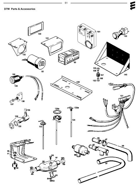
D7W Parts & Accessories 51
52 Ref. No. Description Part Number 1 Combustion air blower 24 V 25 1667 99 15 00 • 12 V 20 1673 99 15 00 • • 12 V 25 1807 99 15 00 • 2 Flame tube 25 1667 19 00 00 • 20 1673 19 00 00 • 25 1666 19 00 00 • 25 1806 19 00 00 • 3 Water pump 12 V 20 1673 25 01 00 • • • 24 V 25 1667 25 01 00 • 4 Glow plug harness 25 1667 01 04 00 • 20 1673 01 04 00 • • 5 Temperature sensor 25 1670 01 05 00 • • • 25 1806 99 01 05 • 6 Flame sensor 20 1645 01 06 00 • • • 6a 25 1769 01 02 00 • 7 Partial-load resistor 12 V 20 1673 01 07 00 • • 24 V 25 1667 01 07 00 • 7a Cable section with partial-load resistor 25 1807 01 01 00 • 8 Resetable overheat switch 20 1677 41 00 00 • • • 8a 25 1806 99 40 00 • 9 Water jacket 20 1673 99 01 01 • • • 9a 25 1806 01 03 00 • 10 Heat exchanger 20 1673 01 00 01 • • • • 11 Base 25 1676 01 00 03 • • • • 12 Grommet 20 1645 01 00 05 • • • • 13 Grommet 20 1645 01 00 06 • • • • 14 Cover 20 1645 01 00 11 • • • • 15 Glow plug 25 1830 01 01 00 • • • • 15a Glow plug screen 25 1666 10 00 01 • • • • 16 Retaining spring 20 1673 01 00 08 • • • 17 Series resistor 25 1667 01 00 01 • 18 Clamp 90mm-110mm 10 2065 09 01 10 • • • • 19 Clamp 46mm - 70mm CA1 10 047 • • • • 20 Holding strap 209 31 074 • • • • 21 Snap ring 171 19 250 • • • 22 Self tapping screw(hardware) 109 10 022 • • • 22a 103 10 310 • • • 22b 109 00 042 •
- Page 2 and 3: Table of contents D7W Boxed I. Intr
- Page 4 and 5: 3 2. Heater Warnings Warning To Ins
- Page 6 and 7: 5 4. Principal Dimensions D7W Boxed
- Page 8 and 9: 7 II. Installation Procedures 1. He
- Page 10 and 11: 9 When being used to provide bunk h
- Page 12 and 13: 11 B) Fuel Metering Pump If the pum
- Page 14 and 15: 13 5. Electrical Connections Cautio
- Page 16 and 17: 15 7. Operating Switches A Push/Pul
- Page 18 and 19: 17 III Heater Operation 3. Running
- Page 20 and 21: 6. Operational Flow Chart 19
- Page 22 and 23: 21 IV. Maintenance Troubleshooting
- Page 24: 23 C. Self Diagnostics Troubleshoot
- Page 29 and 30: 28 Table 1 - Components Resistance
- Page 31 and 32: Figures IV F 30
- Page 33 and 34: 32 Figure IV I When replacing the g
- Page 35 and 36: 34 Figure IV O 7A. Flame Sensor Rep
- Page 37 and 38: 36 10. Water Pump Replacement - Bef
- Page 39 and 40: Universal Model Boxed Model 25 1807
- Page 41 and 42: 40 3. Universal Models 25 1807, 25
- Page 43 and 44: D7W Universal Model 25 1807 42
- Page 45 and 46: D7W Boxed with Espar Heat Exchanger
- Page 47 and 48: D7W Boxed Freightliner Model 25 180
- Page 49 and 50: 48 D7W Parts Diagram Main Heater Co
- Page 51: 50 Universal Parts Models 25 1807 2
- Page 55 and 56: 54 Ref. No. Description Part Number
- Page 57 and 58: 56 Ref. No. Description Part Number
<strong>D7W</strong> Parts & Accessories<br />
51


