D7W TS.pdf - Espar
D7W TS.pdf - Espar D7W TS.pdf - Espar
39 2. General Specifications D7W Universal Model 25 1666 05 25 1667 05 Heat Output (±10%)............................................. Current at 12v (±10%)........................................ Current at 24v (±10%)........................................ 24,000 BTU (7 Kw) -High 6,000 BTU (1.75 Kw) -Low 26.0 amps/hr - Start (1-2 minutes) 7.5 amps/hr - Running High 4.2 amps/hr - Running Low 22.0 amps/hr - Start (1-2 minutes) 3.8 amps/hr - Running High 2.0 amps/hr - Running Low Fuel Consumption (±5%)........................................ High Low Heat Heat US Gal/hr 0.24 0.06 Litre/hr 0.90 0.22 Coolant Pump Flow (±10%)................................. 420 US Gal/hr 1600 Litre/hr Coolant Temperature................................. 176° F to 201° F (80° C to 95° C) Range (±5%) Overheat Temperature ................................. Shutdown (±10%) Operating Voltage Range................................. 275°F (135°C) 10.5 to 14.0 vdc at 12vdc 21.0 to 28.0 vdc at 24 vdc Note: The heater control box is equipped with a low voltage cutout to prevent battery drain and a high voltage cutout to protect the heater’s electrical parts.
40 3. Universal Models 25 1807, 25 1666, 25 1667, 25 1673 1. Heater Location and Mounting - Locate heater in a protected area (eg. storage compartment, step box, engine compartment). - Situate heater below the normal coolant level of the engine. - Guard against excessive road spray. - Keep coolant hoses, fuel lines and electrical wiring as short as possible. - Do not mount heater inside the vehicle passenger area. - Mount using saddle bracket provided (refer to template pattern shown). 2. Heater Plumbing - Refer to D7W Boxed plumbing section (pg. 7) 3. Fuel System - Refer to D7W Boxed fuel system section (pg. 9). 4. Electrical Connections (Universal 25 1666/67 & Boxed 25 1666) Power - 2 core harness (red & brown). Harness - Red wire direct to vehicle battery (+) in line fuse. - Brown wire to battery ground. Switch - 3 core harness (red, brown & yellow) Harness Run to location of switch. Fuel Pump Harness - 2 core harness (green & green) - Run to location of fuel pump 5. Exhaust Connections - A 24mm flexible stainless steel exhaust pipe (50”long), exhaust clamp and holder are provided with the kit. - Secure pipe to heater exhaust outlet and run to an open area to the side or rear of the vehicle so that fumes cannot build up and enter the cab or be sucked in by the heater combustion air blower. - Refer to safety warnings on pg.13 of D7W Boxed version.
- Page 2 and 3: Table of contents D7W Boxed I. Intr
- Page 4 and 5: 3 2. Heater Warnings Warning To Ins
- Page 6 and 7: 5 4. Principal Dimensions D7W Boxed
- Page 8 and 9: 7 II. Installation Procedures 1. He
- Page 10 and 11: 9 When being used to provide bunk h
- Page 12 and 13: 11 B) Fuel Metering Pump If the pum
- Page 14 and 15: 13 5. Electrical Connections Cautio
- Page 16 and 17: 15 7. Operating Switches A Push/Pul
- Page 18 and 19: 17 III Heater Operation 3. Running
- Page 20 and 21: 6. Operational Flow Chart 19
- Page 22 and 23: 21 IV. Maintenance Troubleshooting
- Page 24: 23 C. Self Diagnostics Troubleshoot
- Page 29 and 30: 28 Table 1 - Components Resistance
- Page 31 and 32: Figures IV F 30
- Page 33 and 34: 32 Figure IV I When replacing the g
- Page 35 and 36: 34 Figure IV O 7A. Flame Sensor Rep
- Page 37 and 38: 36 10. Water Pump Replacement - Bef
- Page 39: Universal Model Boxed Model 25 1807
- Page 43 and 44: D7W Universal Model 25 1807 42
- Page 45 and 46: D7W Boxed with Espar Heat Exchanger
- Page 47 and 48: D7W Boxed Freightliner Model 25 180
- Page 49 and 50: 48 D7W Parts Diagram Main Heater Co
- Page 51 and 52: 50 Universal Parts Models 25 1807 2
- Page 53 and 54: 52 Ref. No. Description Part Number
- Page 55 and 56: 54 Ref. No. Description Part Number
- Page 57 and 58: 56 Ref. No. Description Part Number
40<br />
3. Universal Models 25 1807, 25 1666, 25 1667,<br />
25 1673<br />
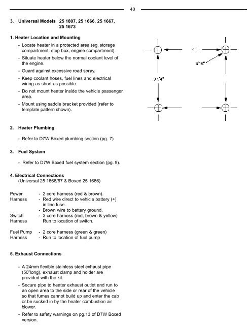
1. Heater Location and Mounting<br />
- Locate heater in a protected area (eg. storage<br />
compartment, step box, engine compartment).<br />
- Situate heater below the normal coolant level of<br />
the engine.<br />
- Guard against excessive road spray.<br />
- Keep coolant hoses, fuel lines and electrical<br />
wiring as short as possible.<br />
- Do not mount heater inside the vehicle passenger<br />
area.<br />
- Mount using saddle bracket provided (refer to<br />
template pattern shown).<br />
2. Heater Plumbing<br />
- Refer to <strong>D7W</strong> Boxed plumbing section (pg. 7)<br />
3. Fuel System<br />
- Refer to <strong>D7W</strong> Boxed fuel system section (pg. 9).<br />
4. Electrical Connections<br />
(Universal 25 1666/67 & Boxed 25 1666)<br />
Power - 2 core harness (red & brown).<br />
Harness - Red wire direct to vehicle battery (+)<br />
in line fuse.<br />
- Brown wire to battery ground.<br />
Switch - 3 core harness (red, brown & yellow)<br />
Harness Run to location of switch.<br />
Fuel Pump<br />
Harness<br />
- 2 core harness (green & green)<br />
- Run to location of fuel pump<br />
5. Exhaust Connections<br />
- A 24mm flexible stainless steel exhaust pipe<br />
(50”long), exhaust clamp and holder are<br />
provided with the kit.<br />
- Secure pipe to heater exhaust outlet and run to<br />
an open area to the side or rear of the vehicle<br />
so that fumes cannot build up and enter the cab<br />
or be sucked in by the heater combustion air<br />
blower.<br />
- Refer to safety warnings on pg.13 of <strong>D7W</strong> Boxed<br />
version.


