D7W TS.pdf - Espar
D7W TS.pdf - Espar
D7W TS.pdf - Espar

Create successful ePaper yourself
Turn your PDF publications into a flip-book with our unique Google optimized e-Paper software.
21<br />
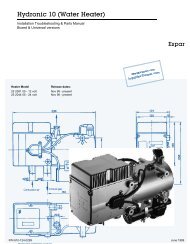
IV. Maintenance Troubleshooting and Repairs<br />
1. Recommended Periodic Maintenance<br />
- Remove the glow plug and inspect for carbon<br />
build up. Clean or replace.<br />
- Remove the glow plug screen and inspect for<br />
carbon build up. Clean or replace. If cleaning is<br />
required, use brass brush (<strong>Espar</strong> part number<br />
CA0 05 003).<br />
- Make sure vent hole is open. Espa<br />
recommends the use of non detergent 100%<br />
volatile carburetor cleaner and an air gun will also<br />
help. Remove loose carbon from the glow plug<br />
chamber.<br />
- Check coolant hoses, clamps, and make sure all<br />
valves are open. Maintain the engine<br />
manufacturers recommended coolant level and<br />
ensure that the heater is properly bled after<br />
service on or involving the coolant system.<br />
- Run your heater at least once a month during the<br />
year (for a minimum of 15 minutes).<br />
- Maintain your batteries and all electrical<br />
connections in good condition. With insufficient<br />
power the heater will not start. Low and high<br />
voltage cutouts will shut the heater down<br />
automatically.<br />
- Use fuel suitable for the climate (see engine<br />
manufacturers recommendations). Blending used<br />
engine oil with diesel fuel is not permitted.<br />
2. Troubleshooting<br />
A. Basic Troubleshooting<br />
In the event of failure there are several items which<br />
should be checked first before any major<br />
roubleshooting is done.<br />
Check<br />
- Circuit breakers and Fuses.<br />
- For breaks on Glow Plug coil.<br />
- Electrical lines and connections<br />
- For interference in Combustion air and Exhaust<br />
pipes.<br />
- That there is fuel in the tank.<br />
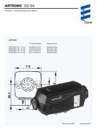
- Has the overheat switch triggered? Figure IV A<br />
Press the raised knob of the rubber cover to reset<br />
the overheat switch located below.<br />
Figure IV A<br />
If a fault can’t be detected follow one of the other<br />
troubleshooting methods outlined in this manual