D7W TS.pdf - Espar
D7W TS.pdf - Espar
D7W TS.pdf - Espar

Create successful ePaper yourself
Turn your PDF publications into a flip-book with our unique Google optimized e-Paper software.
Table of contents<br />
<strong>D7W</strong> Boxed<br />
I. Introduction 1) General Specifications Page 1-5<br />
2) Heater Warnings<br />
3) Introduction<br />
4) Principal Dimensions<br />
5) Heater Components<br />
II. Installation Procedures 1) Heater Location Page 6-15<br />
2) Heater Mounting<br />
3) Heater Plumbing<br />
4) Fuel System<br />
5) Electrical Connections<br />
6) Exhaust Connection<br />
7) Operating Switches<br />
8) Optional Thermostat For Bunk Heat Exchanger<br />
III. Heater Operation 1) Pre- Start Procedures Page 16-20<br />
2) Start-Up<br />
3) Running<br />
4) Switching Off<br />
5) Safety Equipment<br />
6) Operational Flow Chart<br />
7) Wiring Diagram<br />
IV. Maintenance, 1) Recommended Periodic Maintenance Page 21-37<br />
Troubleshooting & 2) Troubleshooting<br />
Repairs 3) Fuel Quantity Test<br />
4) Repair Steps<br />
Appendix:<br />
V. Heater Models 1) Principal Dimensions (25 1807) Page 38-48<br />
Universal 25 1807 2) General Specifications (25 1666/25 1667)<br />
25 1666 3) Location, Mounting, Plumbing, Fuel, Electrical, Exhaust<br />
25 1667 4) Freightliner<br />
Freightliner 5) Wiring Diagrams<br />
VI. Heater Parts Section 1) Parts Diagram - Main Heater Components Page 49-59<br />
2) <strong>D7W</strong>Boxed - Parts Diagram<br />
3) Universal - Parts Diagram<br />
4) Parts & Accessories Diagram<br />
5) Description & Part #’s<br />
Special Notes<br />
Note: Highlight areas requiring special attention or clarification.<br />
Caution: Indicates that personal injury or damage to equipment may occur unless specific<br />
guidelines are followed.<br />
Warning: Indicates that serious or fatal injury may result if specific guidelines are not followed.
2<br />
1. General Specifications<br />
Model 25 1807 05<br />
Heat Output (±10%)<br />
Current at 12v (±10%)<br />
24,000 BTU (7 Kw) -High<br />
6,000 BTU (1.75 Kw) -Low<br />
24.6 amps/hr - Start (1-2 minutes)<br />
5.8 amps/hr - Running High<br />
4.2 amps/hr - Running Low<br />
Fuel Consumption (±5%) High Low<br />
Heat<br />
Heat<br />
US Gal/hr 0.24 0.06<br />
Litre/hr 0.90 0.22<br />
Coolant Pump Flow (±10%)<br />
420 US Gal/hr<br />
1600 Litre/hr<br />
Coolant Temperature 176° F to 201° F (80° C to 95° C)<br />
Range (±5%)<br />
Overheat Temperature<br />
Shutdown (±10%)<br />
Low Voltage Shutdown<br />
High Voltage Shutdown<br />
275°F (135°C)<br />
10.5 Volts<br />
15 Volts
3<br />
2. Heater Warnings<br />
Warning To Installer:<br />
Correct installation of this heater is necessary to ensure safe and<br />
proper operation. Read and understand this manual before<br />
attempting to install a heater.<br />
Warning - Explosion Hazard<br />
- Heater must be turned off while re-fueling.<br />
- Do not install heater in enclosed areas where combustible fumes may be present.<br />
- Do not install heaters in engine compartments of gasoline powered boats.<br />
Warning - Fire Hazard<br />
- Install the exhaust system so it will maintain a minimum distance of 2” from any flammable or heat<br />
sensitive material.<br />
- Ensure that the fuel system is intact and there are no leaks.<br />
Warning - Asphyxiation Hazard<br />
- Route the heater exhaust so that exhaust fumes cannot enter any passenger<br />
compartments.<br />
- If running exhaust components through an enclosed compartment, ensure that it is vented to<br />
the outside.<br />
Warning - Safety Hazard on Coolant Heaters Used With Improper Antifreeze Mixtures<br />
- The use of ESPAR coolant heaters requires that the coolant in the system to be heated contain a<br />
proper mixture of water and antifreeze to prevent coolant from freezing or slushing.<br />
- If the coolant becomes slushy or frozen, the heater’s coolant pump cannot move the coolant<br />
causing a blockage of the circulating system. Once this occurs,<br />
pressure will build up rapidly in the heater and the coolant hose will either burst or blow off at the<br />
connection point to the heater.<br />
- This situation could cause engine damage and/or personal injury. Extreme care should be taken<br />
to ensure a proper mixture of water and antifreeze is used in the coolant system.<br />
- Refer to the engine manufacturer’s or coolant manufacturer’s recommendations for<br />
your specific requirements.<br />
Note:<br />
During electrical welding work on the vehicle disconnect the power to the heater in order to<br />
protect the control unit.<br />
Failure to follow all these instructions could cause serious or fatal injury.<br />
Direct questions to <strong>Espar</strong> Heater Systems USA 1-800-387-4800<br />
CDA 1-800-668-5676
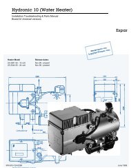
4<br />
3. Introduction<br />
The <strong>Espar</strong> <strong>D7W</strong> is a diesel fired 24,000 BTU/hr<br />
coolant heater, quality engineered to provide a<br />
dependable means of engine and sleeper heating.<br />
The heater can be purchased either in a<br />
weather-resistant steel box to protect it and provide<br />
for ease of installation or in a universal form.<br />
The heater simply pumps coolant from the<br />
engine, heats it and returns it to the engine.<br />
When used to provide sleeper heat, the coolant<br />
is pumped through the sleeper heat exchanger<br />
prior to returning to the engine. Since the heater<br />
runs on diesel fuel and 12 volt power, it is able to<br />
perform this completely independent of the vehicle<br />
engine. A temperature regulating switch in<br />
the unit senses the coolant temperature and regulates<br />
the heater between a low of 176°F (80°C)<br />
and a high of 201°F (94°C).<br />
The heater may be operated from the vehicle cab<br />
by a push/pull switch, a pre-select timer or a<br />
combination of both.<br />
The temperature sensor and overheat switch<br />
form only a part of the safety features which<br />
make this heater a safe and dependable unit.
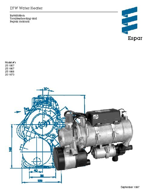
5<br />
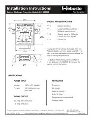
4. Principal Dimensions<br />
<strong>D7W</strong> Boxed Model 25 1807<br />
Figure 1A<br />
10.75”<br />
8.25”<br />
15.25”
5. Heater Components<br />
Figure IB<br />
6
7<br />
II.<br />
Installation Procedures<br />
1. Heater Locations<br />
Select the best mounting location while adhering to<br />
the following conditions:<br />
A<br />
- Situate the heater below the normal coolant<br />
level of the engine.<br />
- Guard against excessive road spray.<br />
- Keep coolant hoses, fuel lines and electrical<br />
wiring as short as possible.<br />
2. Heater Mounting<br />
Mount the heater using the four (4) shock mounts<br />
provided and one of the following mounting<br />
methods: Figures IIA.<br />
- Use the Cross Frame Mounting Tray (A) to<br />
mount the heater behind the cab and on top<br />
of the frame rails.<br />
- Use the Side Mount Bracket (B) to mount the<br />
heater on the side of the frame rail.<br />
- Use a spare step box or battery box.<br />
B<br />
Figures IIA
8<br />
3. Heater Plumbing<br />
Connect the heater to the the engine coolant system<br />
while considering these following points<br />
- Install hose fitting in existing holes in the engine<br />
block (these will have blanking plugs in them).<br />
- Full flow shut off valves should be installed on<br />
the pickup and return hoses at the engine.<br />
- Alternatively “T” piece connectors in existing<br />
coolant hoses can be used if no blanking plugs<br />
are available<br />
- Ensure proper coolant flow by using a minimum<br />
of 3/4” hoses.<br />
- Keep the coolant pick up point as low as<br />
possible on the engine to reduce air in the<br />
system.<br />
- Take coolant from a high pressure point and<br />
return it to a lower pressure point. (eg. back of<br />
block to suction side of water pump). Ensure<br />
that engine and heater are pumping fluids in the<br />
same direction.<br />
- Ensure proper heat distribution by keeping pick<br />
up point and return point as far apart as<br />
possible.<br />
- Check flow rate through heater by measuring<br />
the incoming coolant temperature and the out<br />
going temperature. The rise in temperature<br />
should not exceed 18°F (10°C). If the<br />
temperature rise exceeds 18°F (10°C),<br />
modifications should be made to increase the<br />
flow rate. Check for restrictions in heat<br />
exchanger and fittings.<br />
- If a bunk heat exchanger is incorporated into the<br />
system, proper plumbing layouts must be<br />
followed. (Refer to Figure II B and Figures IIB 1<br />
on following page for specific guidelines.).<br />
Caution: If your bunk heater exchanger has a flow<br />
control valve integrated into it, provisions<br />
must be made to ensure that flow through<br />
the <strong>Espar</strong> heater cannot be blocked.<br />
<strong>D7W</strong>B plumbed for engine pre-heat<br />
Figure IIB<br />
Note:<br />
The coolant must contain a minimum of<br />
10% antifreeze at all times as a protection<br />
against corrosion. Fresh water will corrode<br />
internal heater parts.
9<br />
When being used to provide bunk heat with a heat<br />
exchanger the <strong>D7W</strong>B should be plumbed and wired to<br />
one of the following methods.<br />
1. <strong>D7W</strong>B plumbed with an<br />
<strong>Espar</strong> heat exchanger.<br />
Figures IIB1<br />
2. <strong>D7W</strong>B plumbed with an<br />
OEM heat exchanger.<br />
Note:<br />
By pass must be used to ensure that<br />
coolant flow can’t be completely stopped.<br />
<strong>D7W</strong> Thermostat Options<br />
1. <strong>D7W</strong>B wiring schematics for<br />
the <strong>Espar</strong> heat exchanger.<br />
2. <strong>D7W</strong>B wiring schematics for<br />
OEM heat exchanger.
10<br />
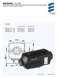
4. Fuel System<br />
The <strong>D7W</strong>B is most commonly provided with the<br />
fuel metering pump mounted inside the box.This<br />
is to reduce installation time and to protect the<br />
pump from corrosion. If specifications cannot be<br />
met the pump must be mounted externally. Refer<br />
to Figure IIC for connections and specifications.<br />
All parts necessary to do the installation are<br />
included in the kit as shown in Figure IIC.<br />
N o t e : Fuel line limits must not be ex c e e d e d .<br />
Ensure that the fo l l owing conditions are<br />
m e t .<br />
Bottom of the fuel metering pump must be<br />
within a height of 2’6” of the bottom of the<br />
fuel pick-up pipe.<br />
Fuel metering pump must be within a total<br />
distance of 6’6” from the fuel pick-up pipe.<br />
Fuel System Tolerances<br />
Figure IIC<br />
Note: Butt joints and clamps on<br />
all connections.<br />
1. Fuel Pick-Up Pipe 5. 9mm Clamp<br />
2. 11mm Clamp 6. 3.5mm Rubber Connector<br />
3. 5.0mm Fuel Line 7. 2.0mm White Plastic Fuel Line<br />
4. Fuel Metering Pump
11<br />
B) Fuel Metering Pump<br />
If the pump needs to be mounted externally follow<br />
these guidelines:<br />
Choose a protected mounting location close to<br />
the fuel pick-up pipe and heater.<br />
Using the bracket and rubber mount provided,<br />
install pump as shown in Figure II D.<br />
Note: Proper mounting angle of the pump is<br />
necessary to allow any air or vapor in the<br />
fuel lines to pass through the pump rather<br />
than cause a blockage.<br />
Fuel Metering Pump Installation<br />
Figure II D:<br />
C) Fuel Line<br />
- Route fuel lines from the fuel pick-up pipe to the<br />
fuel metering pump then to the heater.<br />
- Use fuel lines provided.<br />
- Other sizes or types of fuel lines may inhibi<br />
proper fuel flow.<br />
- Make proper butt joints using clamps and<br />
connector pieces as shown in Figure II E.<br />
- Use a sharp utility knife to cut plastic fuel lines<br />
to avoid burrs.<br />
Figure II E
12<br />
D) Fuel Pick-Up Pipe Installation<br />
(Standard Pick-Up)<br />
- Choose a protected mounting location close to<br />
the pump and heater. A spare fuel sender<br />
gauge plate provides an ideal mounting<br />
location.<br />
- Drill the mounting holes as shown in Figure II F.<br />
- Cut the fuel pick-up pipe to length.<br />
- Mount the fuel pick-up pipe as shown in<br />
FigureIIG.<br />
- Lower the fuel pick-up pipe (with reinforcing<br />
washer) into the tank using the slot created by<br />
the two 1/4” holes.<br />
- Lift the assembly into position through the 1”<br />
hole.<br />
- Assemble the rubber washer, metal cup washer<br />
and nut.<br />
Figure II F<br />
Note: Drill the two 1/4” holes first.<br />
Figure II G<br />
Fuel Pick-Up Pipe<br />
Nut<br />
( Optional Pick-Up Pipe with NPT fitting )<br />
Sheet Metal Washer<br />
Rubber Gasket<br />
Steel Safety Washer<br />
Holding Tabs<br />
Allow 4” from fuel pick-up<br />
to tank bottom. Allow<br />
only 1” for flat bottom<br />
tanks.<br />
End tip of the fuel pick-up<br />
pipe should have angle<br />
so as to avoid picking up<br />
dirt and subsequent<br />
blockage<br />
- Remove an existing plug from the top of the<br />
fuel tank.<br />
- Cut the fuel pick-up pipe to length.<br />
- Secure the fuel pick-up pipe into position using<br />
the combined NPT compression fitting as<br />
shown in Figure II H.<br />
Figure II H<br />
Note: NPT fittings are available in various<br />
sizes (Refer to parts section).
13<br />
5. Electrical Connections<br />
Caution:<br />
To avoid potential short circuit<br />
damage during installation, Make<br />
connection to the positive terminal at<br />
battery after all electrical connections<br />
are complete.<br />
All harnesses should connect to mating plugs atthe<br />
heater box.<br />
A) Power Harness....................................................<br />
B) Switch Harness.....................................................<br />
C) Fuel Metering Pump Harness...............................<br />
D) Bunk Heat Exchanger (optional).......................<br />
- 2 core harness (red and brown).<br />
- Connect red wire to vehicle battery (+), use ring<br />
terminal provided.<br />
- Connect brown wire to vehicle battery (-), use ring<br />
terminal provided.<br />
- 5 core harness [(red, brown, yellow, blue)<br />
black-optional, for bunk fan power supply]<br />
- Fuel Metering Pump Harness is pre-connected<br />
when box is provided with pump pre-mounted.<br />
- If mounted externally, connect wires to fuel<br />
metering pump using single terminals and rubber<br />
protective boots provided with the heater- no<br />
polarity required ).<br />
- 2 core harness (green, green).<br />
- Connect fuel metering pump harness using two<br />
single connectors. Figure IIa.<br />
- single black wire from switch connector.<br />
- connect as described in Heat Exchanger<br />
plumbing section. (pg.8)<br />
Figure II I<br />
A<br />
B<br />
D<br />
Figure II Ia<br />
Note:<br />
All harnesses should be cut to length.<br />
All exposed electrical connections should<br />
be coated with protective grease.<br />
C
14<br />
6 Exhaust Connection<br />
A 30mm flexible stainless steel exhaust pipe (1<br />
meter long), exhaust clamps and holders are<br />
provided with the heater kit. Connect the<br />
exhaust as follows:<br />
Caution:<br />
Run exhaust so that it cannot be<br />
plugged by dirt, water or snow.<br />
Ensure the outlet does not face into<br />
the vehicle slip stream.<br />
Install exhaust pipe with a slight<br />
slope or drill 5mm holes in lowest<br />
point to allow water to run off.<br />
Any restriction in exhaust will cause<br />
operational problems.<br />
Feed the exhaust pipe through the silicone<br />
(white) gasket on the bottom of the box. Run to<br />
an open area to the rear or side of the vehicle so<br />
that fumes can not build up and enter the cab or<br />
the heater box.<br />
Secure the exhaust pipe internally at the heater<br />
and externally using clamps and holders provided.<br />
Figure II J.<br />
Figure II J<br />
Warning: The exhaust is hot, keep a<br />
minimum of 2” clearance from any heat<br />
sensitive material<br />
Warning: Route exhaust so that the<br />
exhaust fumes cannot enter the passenger<br />
compartment.
15<br />
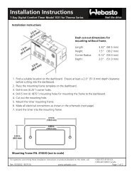
7. Operating Switches<br />
A Push/Pull Switch is supplied with the heater, an<br />
optional 99 Hour Digital Timer or a 7 Day Timer are<br />
also available. Connect the operating switch as follows.<br />
A. Push/Pull Switch<br />
- Mount switch in a location where it is easily<br />
accessible.<br />
- Mount using hardware supplied.<br />
- Connect the 25’ switch harness to the<br />
connector at the heater and run the harness to<br />
the switch location.<br />
- Cut harness to length at the switch and install<br />
terminals.<br />
- Connect wiring as shown in Figure II K.<br />
Figure II K<br />
Control Wiring<br />
Push/Pull Switch<br />
Brown - 31<br />
Red - K (15)<br />
Yellow - 15 (K)<br />
Note<br />
Wired as above the switch light glows<br />
when pulled out and is off when<br />
pushed in.<br />
B. 99 Hour Digital Timer<br />
This timer is pre-set by <strong>Espar</strong> to operate the heater<br />
for one (1) hour only. If an alternative run time setting<br />
is desired refer to the instructions provided with<br />
the timer.<br />
- Mount the timer using a 2” hole in the dash or<br />
the optional mounting bracket.<br />
- Mount timer using hardware supplied.<br />
- Connect the 25’ switch harness to the<br />
connector at the heater and run the harness to<br />
the switch location.<br />
- Cut harness to length and terminate wires.<br />
- Attach using connector provided.<br />
Figure II L<br />
Red-Red<br />
Yellow-Yellow<br />
Brown-Brown
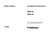
16<br />
C. 7 Day Timer<br />
The 7 day timer is capable of setting up to 3 preset<br />
start times within 24 hrs. or 1 start time with in 7<br />
days. It also has other functions such as a current<br />
time display and a heater numeric fault code. Refer<br />
to instructions provided with timer for setting<br />
options.<br />
- Mount timer and bracket in a suitable location.<br />
- Connect the 25’ switch harness to the<br />
connector at the heater and run the harness to<br />
the switch location.<br />
- Cut harness to length at the switch and install<br />
terminals.<br />
- Connect switch harness to timer..Figure II M<br />
- Refer to timer instructions for other wiring<br />
options.<br />
Figure II M<br />
8. Optional Thermostat for Bunk Heat Exchanger<br />
This thermostat is used to control the fan motor of<br />
the heat exchanger (OEM or optional <strong>Espar</strong> Heat<br />
Exchanger) inside the truck’s sleeper, thereby<br />
allowing for interior cab heating.<br />
- Mount the thermostat in a location where it is<br />
easily accessible and it’s temperature sensor is<br />
representative of the area being heated.<br />
- Mount using the mounting slots in it’s base.<br />
- Connect wiring as shown on page 8<br />
Figure II N
17<br />
III<br />
Heater Operation<br />
3. Running<br />
1. Pre-Start Procedures<br />
Upon completion of installation prepare the heater<br />
as follows:<br />
- Check all fuel, electrical and plumbing<br />
connections.<br />
- Refill the engine coolant<br />
- Bleed air from the coolant system by loosening<br />
the top heater hose to allow air to escape.<br />
Resecure the heater hose.<br />
- Run engine to further bleed the system.<br />
- Top up engine coolant.<br />
2. Start Up<br />
Once switched on the following sequence occurs:<br />
- Combustion air blower starts.<br />
- Water pump starts.<br />
- Control unit checks all functions.<br />
- Glow plug begins to preheat combustion<br />
chamber.<br />
- Control unit checks input voltage (under or over<br />
voltage will cause heater to shut down).<br />
- After the 20-50 second combustion chamber<br />
preheat the fuel pump will start.<br />
- Once ignition takes place the flame sensor will<br />
automatically switch the glow plug off<br />
(ignition time: 1-3 minutes maximum).<br />
Note: If the heater fails to start the first time it will<br />
automatically attempt a second start. If<br />
unsuccessful the heater will shut down<br />
completely.<br />
Note: On initial start up the heater may require<br />
several start attempts to self prime the fuel<br />
system<br />
Once ignition is successful the following<br />
operations take place:<br />
- Heater runs in full heat mode.<br />
- Once coolant reaches 194°F (90°C) the<br />
heater automatically switches to low heat mode<br />
and continues to run.<br />
- If coolant temperature drops to 176°F (80°C) the<br />
heater will automatically switch back to full<br />
heat mode.<br />
- If coolant temperature continues to rise, the<br />
heater will automatically switch off once coolant<br />
temperature reaches 201°F (94°C).<br />
- The water pump will continue to circulate<br />
coolant to allow the heater to monitor engine<br />
temperature.<br />
- The heater will automatically re-start once<br />
coolant temperature reaches 176°F (80°C).<br />
- The heater will continue to run as described<br />
above until it is switched OFF, either manually,<br />
automatically by a timer or heater malfunction<br />
shutdown.<br />
Note: While in running mode if the heater should<br />
shut down due to flame out, it wil<br />
automatically attempt one restart, if<br />
successful it will continue to run, if not it<br />
shuts down completely.<br />
Note: During operation the heater continually<br />
senses the input voltage from the batteries,<br />
if the input voltage drops to approximately<br />
10.0 volts (20.0 V for a 24 V system) the<br />
heater will automatically shut down.<br />
4. Switching Off<br />
When the heater is switched off, manually or automatically,<br />
it starts a controlled cool down cycle.<br />
- The fuel metering pump stops delivering fuel<br />
and the flame is extinguished.<br />
- The glow plug is re-energized for a 15 second<br />
after glow.<br />
- The combustion air blower and water pump<br />
continue to run for a three (3) minute cool down<br />
cycle, then switch OFF.
18<br />
Warning:<br />
Warning:<br />
The heater must be<br />
switched OFF while any fuel<br />
tank on the vehicle is being<br />
filled.<br />
The heater MUST NOT be<br />
operated in garages or<br />
enclosed areas.<br />
5. Safety Equipment<br />
The control unit, overheat switch and flame sensor<br />
continually monitor heater functions and will shut<br />
down the heater in case of a malfunction.<br />
- The control unit ensures electrical circuits (glow<br />
plug, fuel metering pump, combustion air blower<br />
etc.) are complete prior to starting the heater.<br />
- If the heater fails to ignite within 90 seconds of<br />
the fuel pump being started, the starting proce<br />
dure will be repeated. If the heater again fails to<br />
ignite after 90 seconds of fuel being pumped, a<br />
“no” start safety shutdown” follows.<br />
- If the heater flames out during operation, the<br />
heater automatically attempts to restart. If the<br />
heater fails to ignite within 90 seconds of fuel<br />
delivery, or ignites but flames out again within 3<br />
minutes, “flame out” shutdown follows.<br />
- Overheating due to lack of water, a restriction<br />
or a poorly bled coolant system results in the<br />
safety cutout switch tripping. Fuel delivery will<br />
cease and an “overheat shut down” follows.<br />
- If at any time the voltage drops below 10.0v or<br />
20.0v (for 24V), or rises above 14.0v or 28.0v<br />
(for 24V), “high/low voltage” shutdown follows<br />
(after a 20 second delay).
6. Operational Flow Chart<br />
19
7. Wiring Diagram<br />
<strong>D7W</strong> Boxed Heater<br />
Model 25 1807<br />
20
21<br />
IV. Maintenance Troubleshooting and Repairs<br />
1. Recommended Periodic Maintenance<br />
- Remove the glow plug and inspect for carbon<br />
build up. Clean or replace.<br />
- Remove the glow plug screen and inspect for<br />
carbon build up. Clean or replace. If cleaning is<br />
required, use brass brush (<strong>Espar</strong> part number<br />
CA0 05 003).<br />
- Make sure vent hole is open. Espa<br />
recommends the use of non detergent 100%<br />
volatile carburetor cleaner and an air gun will also<br />
help. Remove loose carbon from the glow plug<br />
chamber.<br />
- Check coolant hoses, clamps, and make sure all<br />
valves are open. Maintain the engine<br />
manufacturers recommended coolant level and<br />
ensure that the heater is properly bled after<br />
service on or involving the coolant system.<br />
- Run your heater at least once a month during the<br />
year (for a minimum of 15 minutes).<br />
- Maintain your batteries and all electrical<br />
connections in good condition. With insufficient<br />
power the heater will not start. Low and high<br />
voltage cutouts will shut the heater down<br />
automatically.<br />
- Use fuel suitable for the climate (see engine<br />
manufacturers recommendations). Blending used<br />
engine oil with diesel fuel is not permitted.<br />
2. Troubleshooting<br />
A. Basic Troubleshooting<br />
In the event of failure there are several items which<br />
should be checked first before any major<br />
roubleshooting is done.<br />
Check<br />
- Circuit breakers and Fuses.<br />
- For breaks on Glow Plug coil.<br />
- Electrical lines and connections<br />
- For interference in Combustion air and Exhaust<br />
pipes.<br />
- That there is fuel in the tank.<br />
- Has the overheat switch triggered? Figure IV A<br />
Press the raised knob of the rubber cover to reset<br />
the overheat switch located below.<br />
Figure IV A<br />
If a fault can’t be detected follow one of the other<br />
troubleshooting methods outlined in this manual
22<br />
B. Manual Troubleshooting<br />
To manually troubleshoot the heater match the fault with the cause and prescribed remedy.<br />
Fault Cause Remedy<br />
Heater runs 5 seconds Glow plug defective.......................................... Replace glow plug.<br />
at start then shuts off. Electric motor defective or blower blocked....... Replace blower.<br />
Harness to fuel metering pump not connected. Check line.<br />
Overheat switch tripped.................................... Reset overheat switch.<br />
Insufficient coolant...................................... Top up coolant.<br />
Coolant circuit not properly bled................. Bleed coolant circuit.<br />
Coolant pump defective.............................. Replace coolant pump, reset safety thermal<br />
switch.<br />
Short circuit in the flame sensor...................... Replace flame sensor.<br />
Heater runs for 30 Under voltage.................................................... Check/Charge battery.<br />
seconds at start then Overvoltage...................................................... Check vehicle charging system.<br />
shuts off. Corrosion on electrical connections................. Clean electrical connections.<br />
Flame goes out in Insufficient fuel................................................. Measure fuel quantity.<br />
low mode. Speed of blower not reduced from high Replace partial load resistor .<br />
to low.<br />
Replace control unit.<br />
Replace change over relay<br />
Flame goes out in Insufficient fuel................................................. Measure fuel quantity.<br />
high mode Vapor lock in fuel line....................................... Fuel gets too hot, change position of fuel lines<br />
Flame sensor defective.................................... Replace flame sensor.<br />
Non-start. Fuel line not filled............................................. Restart, check fuel line.<br />
Safety time (90 sec.) Insufficient fuel................................................. Measure fuel quantity.<br />
exceeded and Defective glow plug.......................................... Replace glow plug.<br />
automatic cutout. No fuel.............................................................. Fill tank<br />
Metering pump seizure.................................... Replace metering pump.<br />
Short circuit at metering pump......................... Check pump.<br />
No pulse at metering pump.............................. Replace control unit.<br />
Automatic cut-out after Flame sensor leads reversed........................... Check connection against wiring diagram.<br />
3-5 minutes. Flame sensor interruption................................ Replace flame sensor.<br />
Insufficient fuel................................................. Measure fuel quantity.<br />
Delayed start Heater in cool down mode................................ Wait for delayed shut-off.<br />
Water temperature still above the triggering Wait until temperature falls below triggering<br />
point for the temperature sensor [approx. point.<br />
176°F (80°C)].<br />
Temperature sensor interruption...................... Replace temperature sensor.
23<br />
C. Self Diagnostics Troubleshooting<br />
The <strong>D7W</strong>Boxed heater is equipped with an automatic<br />
testing capability which can be used to check<br />
for faults. A built-in LED provides a full time diagnostics<br />
display. The Optional 7 Day timer provides<br />
a numeric fault code display. Both are covered on<br />
the following pages.<br />
1. Built-in LED and Diagnostic display.<br />
The indicator and fault code chart are located within<br />
the box (Figures IV B). Definitions to the codes<br />
are found on the next few pages.<br />
LED<br />
Figures IV B<br />
DIAGNOSTIC SIGNALS<br />
FALSE FLAME RECOGNITION<br />
FLAME OUT IN LOW SETTING<br />
FLAME OUT IN HIGH SETTING<br />
GLOW PLUG<br />
BURNER MOTOR DOES NOT TURN<br />
UNDER VOLTAGE<br />
OVERVOLTAGE<br />
NO START SAFETY TIME EXCEEDED<br />
GLOW PLUG RELAY<br />
TEMPERATURE SENSOR<br />
SHORT CIRCUIT, FUEL METERING PUMP<br />
FLAME SENSOR<br />
EXTERNAL ELECTRICAL INTERFERENCE<br />
CONTROL UNIT<br />
OVERHEATING<br />
NORMAL OPERATION<br />
WARNING VOLTAGE - UNDER/OVER<br />
0.3 SECONDS<br />
1.6 SECONDS
27<br />
D. 7 Day Timer Troubleshooting<br />
The 7 day timer (Figure IV C) has a fault code<br />
retrieval device built into the unit. This function<br />
automatically activates if the heater is experiencing<br />
problems.<br />
- Fault codes appear on the LCD display screen.<br />
- These codes can then be translated from the<br />
charts on the previous pages.<br />
Figure IV C<br />
E. Circuit Tester Troubleshooting<br />
The purpose of this tester is to help a service<br />
technician troubleshoot problems faster and more<br />
accurately. It tests individual electrical components,<br />
checks the continuity of each circuit and<br />
runs the heater manually.<br />
Note: To use this tester (P/N CA1 05 010) with<br />
the <strong>D7W</strong> 25 1807 you will require an<br />
adapter-P/N CA1 05 023<br />
1. Initial Set Up<br />
- All switches should be in the “Off” position.<br />
- Plug in the connectors from the tester to the<br />
corresponding ones on the heater harness.<br />
- Ensure proper power, fuel and coolant<br />
connections.<br />
2. Operating Instructions<br />
- Switch the power switch to the “On” position and<br />
the voltmeter will indicate the voltage across<br />
the control unit. The voltage must be between<br />
10.0V and 14.0V, on a 12V system or between<br />
20V and 28V on a 24V system.<br />
- Set the heater switch or timer to run position.<br />
- The red “Switch On” LED should illuminate.<br />
- Test individual components by switching each of<br />
the nine switches on the right side of the tester<br />
to “CHECK” position.<br />
- The ohmmeter will indicate the resistance value<br />
of each component as high or low.<br />
- Compare measured value to componen<br />
resistance chart in Table 1.<br />
- If any mismatch is indicated the component<br />
should be replaced.<br />
- Do not measure more than one component at a<br />
time.<br />
Figures IV D
28<br />
Table 1 - Components Resistance Chart<br />
Component<br />
Combustion Air Blower<br />
Water Pump<br />
Glow Plug<br />
Overheat Switch<br />
Fuel Metering Pump<br />
Temperature Sensor<br />
Flame Sensor<br />
Partial Load Resistor<br />
Heat Exchanger Relay<br />
Resistance<br />
Low<br />
Low<br />
Low<br />
Low<br />
Low<br />
Medium<br />
High when exchanger is cool<br />
Low when exchanger is warm<br />
Low<br />
Low<br />
3. To Manually Run Heater<br />
Start Up:<br />
- Switch combustion air blower switch to “High”<br />
position.<br />
- Combustion motor will run at high speed.<br />
- Switch water pump switch to “On” position.<br />
- Water pump circulates coolant through the<br />
system.<br />
- Switch glow plug to “On” position and wait for<br />
30 seconds.<br />
- Glow plug begins preheating.<br />
Note: Combustion air blower motor speed will<br />
decrease due to voltage drop.<br />
- Switch fuel metering pump switch to<br />
“High” position.<br />
- Fuel metering pump delivers fuel to combustion<br />
chamber and establishes a flame.<br />
Low Heat:<br />
Switch combustion air blower motor<br />
switch to “Low” position.<br />
Switch fuel metering pump switch to<br />
“Low” position.<br />
Note: The heater is now running in low heat mode.<br />
Cool Down:<br />
Switch fuel metering pump switch to<br />
“Off” position.<br />
Switch the combustion air blower motor<br />
switch to “High” position.<br />
Wait for 3 minutes for the heater to cool<br />
down.<br />
Switch combustion air blower motor<br />
switch to “Off” position.<br />
Switch water pump switch to “Off ”<br />
position.<br />
Note: The heater is now off. Turn the power switch<br />
off and disconnect tester.<br />
Note: If the fuel metering pump does not receive<br />
the electric pulses then the overheat switch<br />
may be tripped. Reset the overheat switch.<br />
Check the fuse in tester - if blown<br />
replace with AGC-1.<br />
High Heat:<br />
Once a flame is established<br />
(combustion is heard) wait 30 seconds<br />
then switch the glow plug off. The<br />
heater is now running in high<br />
heat mode.<br />
Note: Combustion air blower motor speed and<br />
fuel metering pump pulse frequency will<br />
increase due to voltage increase.
29<br />
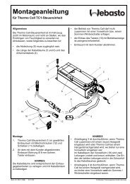
3. Fuel Quantity Test<br />
The fuel Quantity should be tested if the heater has<br />
difficulty starting or maintaining a flame.<br />
Note: Measure the fuel quantity when the battery<br />
is sufficiently charged. At least 11/22V and<br />
at most 13/26V should be applied at the<br />
control unit during measurement.<br />
A).<br />
Preparation<br />
- Detach the fuel line from the heater.<br />
- Insert the fuel line into a measuring glass.<br />
- Connect a voltmeter to terminals A13 (+) and A12<br />
(-) of the control unit.<br />
[C6 (+) and A4 (-) on models 25 1666/1667].<br />
- Disconnect the glow plug leads from the glow plug<br />
and connect a test light across the two leads.<br />
- Switch the heater on and allow the fuel line to<br />
bleed.(approx. 25-55 seconds)<br />
- Switch off the heater and empty the measuring<br />
glass.<br />
B). Measurement<br />
- Switch on the heater.<br />
- Hold the fuel line in the measuring glass while fuel<br />
is being delivered.<br />
- Fuel starts being pumped 25 - 55 seconds after<br />
switch-on.<br />
- Hold the measuring glass at the level of the plug<br />
during measurement.<br />
- Read the voltage at the voltmeter.<br />
- The pump will stop delivering fuel automatically<br />
after 90 seconds.<br />
- Switch off the heater.<br />
C. Evaluation<br />
- Read the fuel quantity in the measuring glass.<br />
- Transpose the readings into the appropriate<br />
diagram. Figures IV F<br />
- The fuel consumption is OK if the intersection of<br />
the two readings are within the limit curves.<br />
- If the intersection is outside the limit curves, inspect<br />
the fuel system and replace fuel metering pump if<br />
necessary.<br />
Note: Do not adjust fuel metering pump.<br />
Adjustments will only provide a tempora ry fix.<br />
Figure IV E<br />
Connect Test Lamp<br />
Control Unit<br />
Voltmeter<br />
Positive line<br />
to voltmeter<br />
Negative line<br />
to voltmeter<br />
Positive line to<br />
voltmeter<br />
Negative line to voltmeter<br />
New<br />
Model 25 1807<br />
Old<br />
Model 25 1666, 1667 1673<br />
Continued on next page.....<br />
Connection of voltmeter to control unit
Figures IV F<br />
30
31<br />
4. Repair Steps<br />
1. Glow Plug Removal, Inspection and Replacement<br />
2. Glow Plug Screen Removal, Inspection and Replacement<br />
3. Series Resistor Removal<br />
4. Cover Removal<br />
5. 12-pin Plug Removal<br />
6. Temperature Sensor Replacement<br />
7. Flame Sensor Replacement<br />
8. Overheat Switch Removal<br />
9. Partial-Load Resistor Removal<br />
10 Water Pump Replacement<br />
11. Combustion Air Blower Removal<br />
12. Flame Tube Removal<br />
13. Heat Exchanger Removal, Inspection and Replacement<br />
14. Cover and Bracket Removal<br />
Figure IV G<br />
1. Glow Plug Removal,<br />
Inspection and Replacement<br />
- Take off the plug cap<br />
- Loosen the hex nut and detach the plug cable<br />
- Unscrew the glow plug<br />
- Inspect glow plug and coil for carbon build up<br />
breaks or metal fatigue<br />
- Clean or replace if necessary<br />
- Re-install in reverse order<br />
2. Glow Screen Removal,<br />
Inspection and Replacement<br />
Figure IV H<br />
- Remove the glow plug<br />
- Remove screen and clean using varsol,<br />
brass wire brush and compressed air<br />
- Replace if necessary<br />
- Clean glow plug chamber to remove<br />
carbon build up<br />
- Re-install screen<br />
continued....
32<br />
Figure IV I<br />
When replacing the glow plug screen,<br />
be sure to insert it in the manner shown<br />
in Figure IV I<br />
3. Series Resistor Removal<br />
(24 volt only)<br />
Figure IV J<br />
- Remove the cap from the series resistor<br />
- Loosen the hex nut<br />
- Detach the cable<br />
- Unscrew the series resistor<br />
4. Cover Removal<br />
- Unclip the cover from the holder<br />
using a screwdriver<br />
Figure IV K<br />
Note when re-installing:<br />
- The cover cap must be fitted<br />
splash-water tight, ensure that<br />
all grommets are properly positioned
33<br />
5. 12 pin Plug Removal<br />
- Remove the cover<br />
- Unclip the plug from the<br />
holder using a screwdriver<br />
- Dismantle the plug<br />
Figures IV M<br />
Figure IV L<br />
Water pump (Brown)<br />
Combustion air blower speed<br />
change relay (Black/Red)<br />
Temperature sensor (Brown)<br />
Temperature sensor (Grey)<br />
Overheat switch (White)<br />
Water pump (Brown)<br />
Combustion air blower (Violet)<br />
Partial load resistor (Red)<br />
Temperature sensor (Brown)<br />
Temperature sensor(Grey)<br />
Overheat switch (White)<br />
Overheat switch (White)<br />
Flame sensor (Grey)<br />
Flame sensor (Grey)<br />
Speed change relay (Black)<br />
Combustion air blower (Brown)<br />
Water pump (Black)<br />
Overheat switch (White)<br />
Flame sensor (Grey)<br />
Flame sensor (Brown)<br />
Partial load resistor (Red)<br />
Combustion air blower (Brown)<br />
Water pump (Black)<br />
<strong>D7W</strong>Boxed<br />
Model 25 1807<br />
Model 20 1673<br />
25 1666<br />
25 1667<br />
6. Temperature Sensor Replacement<br />
Figure IV<br />
- Before removing the sensor, reduce the<br />
excess pressure in the cooling system<br />
by opening the radiator filler cap<br />
- To prevent the coolant from flowing out<br />
pinch the water supply and return hoses shut<br />
- Remove the cover<br />
- Remove the 12 pin plug<br />
- Remove pins 8 and10 from plug housing<br />
(see Figure IV M).<br />
- Unscrew the temperature sensor<br />
- After reinstallation, bleed the water circuit<br />
See repair procedure 15.
34<br />
Figure IV O<br />
7A. Flame Sensor Replacement<br />
Model 25 1807<br />
- Remove the cover<br />
- Remove the 12 pin plug<br />
- Remove pins 7 and 9 from plug housing<br />
- (see Figure IV M)<br />
- Unscrew the flame sensor from the heat exchanger<br />
exhaust port<br />
7B. Flame Sensor Replacement<br />
Model 20 1673<br />
25 1666<br />
25 1667<br />
Figure IV P<br />
- Remove the cover<br />
- Remove the 12 pin plug<br />
- Remove pins 7 and 9 from plug housing<br />
(see Figure IV M).<br />
- Unclip the retaining spring<br />
- Remove the flame sensor from the holder<br />
8A. Overheat Switch Removal<br />
Model 25 1807<br />
- Before removing these, reduce the excess<br />
pressure in the cooling system by opening the<br />
radiator filler cap<br />
- To prevent the coolant from flowing out pinch<br />
the water supply and return hoses shut<br />
- Remove the cover<br />
- Remove the 12 pin plug<br />
- Remove pins 11 and 12 from plug housing<br />
(see Figure IV M).<br />
- Unscrew the cross-recessed screws<br />
- Remove the (spring-loaded) overheat switch<br />
Figure IV Q<br />
Continued....
35<br />
Note when re-installing:<br />
- Use new O ring and seal<br />
- Lubricate prior to installing<br />
- After installation, bleed the water circuit<br />
8B. Overheat Switch Removal<br />
Model 20 1673<br />
25 1666<br />
25 1667<br />
Figure IV R<br />
- Before removing, reduce the excess<br />
pressure in the cooling system by opening<br />
the radiator filler cap<br />
- To prevent the coolant from flowing out pinch<br />
the water supply and return hoses shut.<br />
- Remove the cover<br />
- Remove the 12 pin plug.<br />
- Remove pins 11 and 12 from plug housing<br />
(see Figure IV M).<br />
- Unscrew the overheat switch<br />
Note when re-installing:<br />
- Use new O ring and seal<br />
- Lubricate prior to installing<br />
- After installation, bleed the water circuit<br />
9. Partial-Load Resistor Removal<br />
- Remove the cover<br />
- Remove the 12 pin plug<br />
- Remove pins 5 and 6 from plug housing<br />
(see Figure IV M)<br />
- Remove the retaining clips from the partial-load<br />
resistor<br />
- Remove the partial-load resistor<br />
Figure IV S
36<br />
10. Water Pump Replacement<br />
- Before removing the pump, reduce the excess<br />
pressure in the cooling system by opening the<br />
radiator filler cap.<br />
- To prevent the coolant from flowing out pinch the<br />
water supply and return hoses shut.<br />
- Remove the cover.<br />
- Remove the 12 pin plug.<br />
- Remove pins 1 and 2 from plug housing<br />
(see Figure IV M).<br />
- Undo the fastening clip of the water pump.<br />
- Remove the water pump.<br />
Note when re-installing:<br />
- Use new O ring<br />
- Lubricate prior to installing<br />
- After installation, bleed the water circuit<br />
11. Combustion Air Blower Removal<br />
- Remove the cover.<br />
- Remove the 12 pin plug.<br />
- Remove pins 3 and 4 out of the plug housing<br />
(see Figure 4 M).<br />
- Loosen the fastening screw and remove the<br />
combustion air blower.<br />
Figure IV T<br />
Figure IV U<br />
Note when re-installing:<br />
- Use new O-ring<br />
- Lubricate before installing<br />
12. Flame Tube Removal<br />
- Before removing the flame tube, reduce the excess<br />
pressure in the cooling system by opening the<br />
radiator filler cap<br />
- To prevent the coolant from flowing out pinch<br />
the water supply and return hoses shut<br />
- Remove the heater<br />
- Remove the combustion air blower<br />
- Remove the glow plug cable and - in the case of 24<br />
volt heaters - also the cable from the series resistor<br />
- Remove the flame sensor<br />
- Undo the clamping clip and remove the burner<br />
Note when re-installing:<br />
- Use new O ring<br />
- Lubricate prior to installing<br />
- After installation, bleed the water circuit<br />
Figure IV V
37<br />
13. Heat Exchanger Removal<br />
- Before removing the heat exchanger, reduce the<br />
excess pressure in the cooling system<br />
by opening the radiator filler cap<br />
- To prevent the coolant from flowing out pinch the<br />
water supply and return hoses shut<br />
- Remove the heater<br />
- Remove the flame tube<br />
- Lift the safety over heat switch off the<br />
heat exchanger<br />
- Remove the temperature sensor.<br />
- Lever the heat exchanger out of the water jacket<br />
using screwdrivers<br />
- Remove the heat exchanger from the water jacket<br />
(Figure IV X)<br />
Note when re-installing:<br />
- Use new O ring<br />
- Lubricate prior to installing<br />
- After installation, bleed the water circuit<br />
Figure IV W<br />
Figure IV X<br />
14. Cover and Bracket Removal<br />
- Remove the cover<br />
- Remove the 12 pin plug<br />
- Detach the 2 pin plug<br />
- Remove the partial-load resistor<br />
- Remove all grommets<br />
- Take the bracket off the jacket<br />
Figure IV Y<br />
Note when re-installing:<br />
- The cover cap must be fitted so that it is<br />
splash-water tight, ensure that all grommets<br />
are properly positioned
Universal Model<br />
Boxed Model<br />
25 1807 25 1666 (12V)<br />
25 1666 25 1667 (24V)<br />
25 1667 Freightliner<br />
1. Principal Dimensions (Universal Model 25 1807)
39<br />
2. General Specifications<br />
<strong>D7W</strong> Universal Model 25 1666 05<br />
25 1667 05<br />
Heat Output (±10%).............................................<br />
Current at 12v (±10%)........................................<br />
Current at 24v (±10%)........................................<br />
24,000 BTU (7 Kw) -High<br />
6,000 BTU (1.75 Kw) -Low<br />
26.0 amps/hr - Start (1-2 minutes)<br />
7.5 amps/hr - Running High<br />
4.2 amps/hr - Running Low<br />
22.0 amps/hr - Start (1-2 minutes)<br />
3.8 amps/hr - Running High<br />
2.0 amps/hr - Running Low<br />
Fuel Consumption (±5%)........................................ High Low<br />
Heat<br />
Heat<br />
US Gal/hr 0.24 0.06<br />
Litre/hr 0.90 0.22<br />
Coolant Pump Flow (±10%).................................<br />
420 US Gal/hr<br />
1600 Litre/hr<br />
Coolant Temperature................................. 176° F to 201° F (80° C to 95° C)<br />
Range (±5%)<br />
Overheat Temperature .................................<br />
Shutdown (±10%)<br />
Operating Voltage Range.................................<br />
275°F (135°C)<br />
10.5 to 14.0 vdc at 12vdc<br />
21.0 to 28.0 vdc at 24 vdc<br />
Note: The heater control box is equipped with a<br />
low voltage cutout to prevent battery drain<br />
and a high voltage cutout to protect the<br />
heater’s electrical parts.
40<br />
3. Universal Models 25 1807, 25 1666, 25 1667,<br />
25 1673<br />
1. Heater Location and Mounting<br />
- Locate heater in a protected area (eg. storage<br />
compartment, step box, engine compartment).<br />
- Situate heater below the normal coolant level of<br />
the engine.<br />
- Guard against excessive road spray.<br />
- Keep coolant hoses, fuel lines and electrical<br />
wiring as short as possible.<br />
- Do not mount heater inside the vehicle passenger<br />
area.<br />
- Mount using saddle bracket provided (refer to<br />
template pattern shown).<br />
2. Heater Plumbing<br />
- Refer to <strong>D7W</strong> Boxed plumbing section (pg. 7)<br />
3. Fuel System<br />
- Refer to <strong>D7W</strong> Boxed fuel system section (pg. 9).<br />
4. Electrical Connections<br />
(Universal 25 1666/67 & Boxed 25 1666)<br />
Power - 2 core harness (red & brown).<br />
Harness - Red wire direct to vehicle battery (+)<br />
in line fuse.<br />
- Brown wire to battery ground.<br />
Switch - 3 core harness (red, brown & yellow)<br />
Harness Run to location of switch.<br />
Fuel Pump<br />
Harness<br />
- 2 core harness (green & green)<br />
- Run to location of fuel pump<br />
5. Exhaust Connections<br />
- A 24mm flexible stainless steel exhaust pipe<br />
(50”long), exhaust clamp and holder are<br />
provided with the kit.<br />
- Secure pipe to heater exhaust outlet and run to<br />
an open area to the side or rear of the vehicle<br />
so that fumes cannot build up and enter the cab<br />
or be sucked in by the heater combustion air<br />
blower.<br />
- Refer to safety warnings on pg.13 of <strong>D7W</strong> Boxed<br />
version.
41<br />
4. Freightliner<br />
Plumbing<br />
Freightliner Plumbing Diagram<br />
Wiring (pg.46)<br />
Freightliner Fuel & Electrical Accessories Part #<br />
Internal Harness (complete) 806 103 006<br />
Packard Connectors:<br />
Switch<br />
Thermostat<br />
- Female, 3 hole housing CA1 91 001<br />
- Terminal seal CA1 91 003<br />
- Lock CA1 91 004<br />
- Terminals CA1 90 015<br />
CA1 90 091<br />
- Housing (female 1-hole) CA1 91 042<br />
- Lock CA1 91 045<br />
Power<br />
- Male, 3 hole housing CA1 91 031<br />
- Lock CA1 91 032<br />
- Seal CA1 91 034<br />
- Terminals CA1 90 062<br />
Fuel connectors<br />
- Hose barb CA0 12 008<br />
- Adapter CA0 12 007<br />
- Washer CA3 00 322<br />
90° BulkheadCA0 11 037
<strong>D7W</strong> Universal<br />
Model 25 1807<br />
42
<strong>D7W</strong> Boxed<br />
Model 25 1666 (12V)<br />
25 1667 (24V)<br />
43
<strong>D7W</strong> Boxed with <strong>Espar</strong> Heat Exchanger<br />
Model 25 1666 (12V)<br />
44
45<br />
<strong>D7W</strong> Universal<br />
Model 25 1666 (12V)<br />
25 1667 (24V)
<strong>D7W</strong> Boxed Freightliner<br />
Model 25 1807<br />
46
Bunk Blower Wiring Adapter<br />
Model 25 1666<br />
47
48<br />
<strong>D7W</strong> Parts Diagram<br />
Main Heater Components<br />
Models 25 1807<br />
25 1666/67
49<br />
<strong>D7W</strong> Boxed Parts<br />
Models 25 1807/25 1666
50<br />
Universal Parts<br />
Models 25 1807<br />
25 1666<br />
25 1667<br />
25 1673
<strong>D7W</strong> Parts & Accessories<br />
51
52<br />
Ref.<br />
No. Description Part Number<br />
1 Combustion air blower 24 V 25 1667 99 15 00 •<br />
12 V 20 1673 99 15 00 • •<br />
12 V 25 1807 99 15 00 •<br />
2 Flame tube 25 1667 19 00 00 •<br />
20 1673 19 00 00 •<br />
25 1666 19 00 00 •<br />
25 1806 19 00 00 •<br />
3 Water pump 12 V 20 1673 25 01 00 • • •<br />
24 V 25 1667 25 01 00 •<br />
4 Glow plug harness 25 1667 01 04 00 •<br />
20 1673 01 04 00 • •<br />
5 Temperature sensor 25 1670 01 05 00 • • •<br />
25 1806 99 01 05 •<br />
6 Flame sensor 20 1645 01 06 00 • • •<br />
6a 25 1769 01 02 00 •<br />
7 Partial-load resistor 12 V 20 1673 01 07 00 • •<br />
24 V 25 1667 01 07 00 •<br />
7a Cable section with partial-load resistor 25 1807 01 01 00 •<br />
8 Resetable overheat switch 20 1677 41 00 00 • • •<br />
8a 25 1806 99 40 00 •<br />
9 Water jacket 20 1673 99 01 01 • • •<br />
9a 25 1806 01 03 00 •<br />
10 Heat exchanger 20 1673 01 00 01 • • • •<br />
11 Base 25 1676 01 00 03 • • • •<br />
12 Grommet 20 1645 01 00 05 • • • •<br />
13 Grommet 20 1645 01 00 06 • • • •<br />
14 Cover 20 1645 01 00 11 • • • •<br />
15 Glow plug 25 1830 01 01 00 • • • •<br />
15a Glow plug screen 25 1666 10 00 01 • • • •<br />
16 Retaining spring 20 1673 01 00 08 • • •<br />
17 Series resistor 25 1667 01 00 01 •<br />
18 Clamp 90mm-110mm 10 2065 09 01 10 • • • •<br />
19 Clamp 46mm - 70mm CA1 10 047 • • • •<br />
20 Holding strap 209 31 074 • • • •<br />
21 Snap ring 171 19 250 • • •<br />
22 Self tapping screw(hardware) 109 10 022 • • •<br />
22a 103 10 310 • • •<br />
22b 109 00 042 •
53<br />
Ref.<br />
No. Description Part Number<br />
23 Clip 151 10 051 • • • •<br />
24 Terminal holder 206 31 346 • • • •<br />
25 Terminal holder cover 206 31 347 • • • •<br />
26 O-ring 89x4 320 75 002 • • • •<br />
27 O-ring 17x2.5 320 75 001 • • • •<br />
28 O-ring 7x2 320 75 111 • • • •<br />
29 Clamp for flame tube 152 00 155 • • • •<br />
30 Fuel metering pump 12 V 20 1673 45 00 00 •<br />
12 V 25 1666 45 00 00 • •<br />
24 V 25 1667 45 00 00 •<br />
31 Exhaust pipe w/cap 30mmx1.3M 25 1816 80 08 00 • • • •<br />
32 Exhaust muffler 24mm 20 1690 80 02 00 • • •<br />
30mm 25 1806 80 01 00 •<br />
33 Control unit 12 V 25 1666 50 00 00 • •<br />
24 V 25 1667 50 00 00 •<br />
12 V 25 1732 50 00 04 •<br />
34 Cable harness, universal 20 1673 80 07 00 • • •<br />
25 1807 80 04 00 •<br />
35 Cable 20 1668 80 05 00 • • • •<br />
36 Coolant hose 90° 20 1673 80 00 01 • • • •<br />
37 Coolant hose 180° 20 1673 80 00 03 • • • •<br />
38 Heater mounting bracket 20 1673 80 00 02 • • • •<br />
39 Plastic fuel line 2mm 090 31 117 • • • •<br />
40 Fuel hose 5mm 360 75 350 • • • •<br />
41 Plastic fuel line 4mm 090 31 101 • • • •<br />
42 Rubber mount 6mm 20 1185 00 00 01 • • • •<br />
43 Rubber mount self tapping 20 1673 80 01 01 • • •<br />
44 FMP angle bracket 20 1348 03 00 04 • • • •<br />
45 Double angle bracket 90° 20 1533 88 00 07 • • • •<br />
46 Sleeve 20 1668 80 01 01 • • • •<br />
47 Clamp 20mm-32mm 10 2065 02 00 32 • • • •<br />
48 Pipe clamp 41mm, FMP holder 152 10 040 • • • •<br />
49 Flex. exhaust clamp 26mm 152 61 102 • • •<br />
30-32mm 152 10 061 •<br />
50 Pipe clamp 28mm 152 10 051 • • •<br />
34mm 152 10 043 •<br />
51 Pipe clamp 12mm 152 10 058 • • • •<br />
52 Pipe clamp 10mm 152 00 147 • • • •<br />
53 Hex nut M6 CA3 00 208 • • • •<br />
54 Spring washer 6mm CA3 00 308 • • • •
54<br />
Ref.<br />
No. Description Part Number<br />
55 Bolt M6x16 CA3 00 126 • • •<br />
56 Hex nut M8 CA3 00 209 • • • •<br />
57 Spring washer 8mm CA3 00 309 • • • •<br />
58 Rubber mount 8mm 330 00 036 • • • •<br />
59 Hex bolt 5/16”x1/2” CA3 00 102 •<br />
60 Hex nut 5/16” CA3 00 203 •<br />
61 Sheet-metal screw, B3.9x19 H • • • •<br />
62 Sheet-metal screw, B6.3x13 CA3 00 402 • • • •<br />
63 Sheet-metal screw, B4.8x19 H • • • •<br />
64 Sheet-metal screw, B3.9x32 H • • • •<br />
65 Connecting pipe 20mm 20 1534 88 00 01 • • • •<br />
66 T-piece, 20x20x20mm 20 1673 80 11 00 • • •<br />
67 Reducing piece, 20x18mm 20 1645 89 00 06 • • • •<br />
68 Water thermostat 3x18mm 330 00 160 • • •<br />
69 Current regulator block 203 31 000 • •<br />
70 Relay block 203 00 085 • • • •<br />
71 Hex nut 3mm CA3 00 215 •<br />
71a Lock washer 3mm CA3 00 315 •<br />
72 Bolt M3x30 CA3 00 115-001 •<br />
73 Fuel hose 3.5mm 360 75 300 • • • •<br />
74 Relay 12 V 203 00 065 • • •<br />
24 V 203 00 066 •<br />
74a Relay 12 V 203 00 093 •<br />
75 Fuse holder, bottom 204 31 004 • • • •<br />
76 Fuse holder, cover 204 31 005 • • • •<br />
77 Fuse insert 10A CA1 07 006 • • • •<br />
15A CA1 07 002 • • • •<br />
25A 204 00 089 • • • •<br />
78 Terminal fuse holder, AWG12 206 73 058 • • • •<br />
79 Rubber boot 320 31 120 • • • •<br />
80 Socket male 3 hole 206 31 303 • • •<br />
81 Socket female 3 hole 206 31 012 • • •<br />
82 Flat-pin terminal AWG 14-18 CA1 90 005 • • • •<br />
83 Terminal AWG 14-18 CA1 90 003 • • • •<br />
84 Ring Terminal AWG 10-12 CA1 90 014 • • • •<br />
85 End cap 24mm 25 1482 80 00 01 • • •<br />
30mm 25 1785 80 02 00 •<br />
86 Flex. exhaust tube 24mm x 1.3 M 360 61 292 • • •<br />
30mm x 1.3 M 360 61 300 •<br />
87 Current regulator 12 V 25 1548 01 00 01 • •<br />
87a Current regulator 12 V 203 00 082 •
55<br />
Ref.<br />
No. Description Part Number<br />
88 Cable section 20 1673 80 05 00 • •<br />
89 Clamp 9mm 10 2063 00 90 98 • • • •<br />
90 Clamp 11mm 10 2063 01 10 98 • • • •<br />
92 Timer, 99 hour CA1 00 050 • • • •<br />
without bracket CA1 00 051 • • • •<br />
93 Timer, 7 day 12 V 22 1000 30 12 00 • • • •<br />
24 V 22 1000 30 13 00 • • • •<br />
94 Wide terminal CA1 90 013 • •<br />
95 Coolant pump seal kit 20 1673 25 04 00 • • • •<br />
96 Screw M6x20 H • • • •<br />
97 Integrated fuel filter 20 1312 00 00 06 • • • •<br />
98 Fuel hose nipple 20 1621 45 00 02 • • • •<br />
99 Holder, control unit 25 1714 80 05 01 •<br />
100 Holder 25 1806 01 00 02 •<br />
101 Seal ring, glow plug 25 1830 01 01 01 • • • •<br />
102 Seal, overheat switch 25 1806 01 00 03 •<br />
103 Bracket, overheat switch 25 1806 01 00 02 •<br />
104 Bracket, overheat switch 20 1673 01 00 10 • • •<br />
105 Rubber ring for fuel metering pump 20 1449 00 10 01 • •<br />
106 Fuel metering pump holder 25 1156 20 00 11 • •<br />
107 Exhaust seal 25 1216 88 03 01 • •<br />
108 Cable grommet, square CA0 00 042 •<br />
109 Heavy duty shock mount kit, 8mm CA0 00 062 • •<br />
110 Bolt M8x50 CA3 00128 • •<br />
111 Washer fender 5/16” x1.25” OD CA3 00 305 • •<br />
112 Shock mount 8mm 2 piece CA3 00 128 • •<br />
113 Threaded washer M8 CA3 00 333 • •<br />
114 Spring washer 8mm CA3 00 302 • •<br />
115 Hex nut 8mm CA3 00 209 • •<br />
116 Box, cover CA0 10 031 • •<br />
117 Box, base CA0 10 067 • •<br />
118 Molded hose CA0 11 023 • •<br />
119 Spring loaded clamp CA1 10 046 • •<br />
120 LED, panel mount kit CA1 00 096 •<br />
121 Internal control harness complete (short harness) CA1 60 713 •<br />
CA1 60 708<br />
122 Push pull switch 12V CA1 00 003 • •<br />
123 Fuel pick-up 4mm CA0 12 058 • • • •<br />
124 Custom ring type fuel pick up pipe CA0 12 012 • • • •<br />
124a Gasket CA0 10 040 • • • •<br />
•
56<br />
Ref.<br />
No. Description Part Number<br />
125 Custom straight pick up pipe 16” length CA0 00 030 • • • •<br />
24” length CA0 12 053 • • • •<br />
125a Compression fittings 1/4” NPT CA0 12 044 • • • •<br />
3/8” NPT CA0 00 031 • • • •<br />
1/2” NPT CA0 12 005 • • • •<br />
126 Power cable CA1 65 713 •<br />
127 Switch cable CA1 70 713 •<br />
128 Power and switch cable complete CA1 60 702 • •<br />
129 Replacement coupling ring for power switch cable CA1 91 014-001 •<br />
130 Bezel (7 Day timer) 25 1482 70 01 00 • • • •<br />
131 Mounting bracket (7 Day timer) CA0 10 061 • • • •<br />
132 Mounting bracket (99 hr timer) CA0 00 032 • • • •<br />
133 Washer - bulkhead CA 00 311 • •<br />
134 Bulkhead hose connector CA0 11 011 • •<br />
135 End cap CA0 11 016 • •<br />
136 90° Bulkhead hose connector CA0 11 037 • •<br />
137 Cap for circuit breaker CA1 04 106 •<br />
138 Circuit breaker 30 AMP with cap CA1 07 101 •<br />
139 Cross frame mounting tray CA0 10 022 • •<br />
140 Side frame mounting tray CA0 10 057 • •<br />
141 Grommet for fuel line 20 1280 09 01 03 •<br />
142 Switch connector female CA1 91 071 •<br />
143 Lock for CA1 91 071 CA1 91 073 •<br />
144 Switch connector male CA1 91 072 •<br />
145 Socket AWG 18 for CA1 91 072 CA1 90 258 •<br />
146 Socket AWG 14 for CA1 91 072 CA1 90 259 •<br />
147 Pin AWG 18 for CA1 91 071 CA1 90 257 •<br />
148 Seal plug for CA1 91 072 or CA1 91 071 CA1 91 063 •<br />
149 Lock for CA1 91 072 CA1 91 074 •<br />
150 Switch connector male CA1 91 072 •<br />
151 Power socket AWG10 for CA1 91 062 CA1 90 262 •<br />
152 Power connector male CA1 91 062 •<br />
153 Power connector female CA1 91 061 •<br />
154 Power pin AWG10 for CA1 91 061 CA1 90 261 •<br />
155 Hex nut 5/16” CA3 00 203 •<br />
156 Spring washer 8mm CA3 00 309 • • • •<br />
157 Shock mount 5/16” - 1 piece CA0 00 040 •<br />
158 Hex bolt M6x12 CA3 00 103 •<br />
159 Hex nut M6 CA3 00 208 •<br />
160 Washer 6mm CA3 00 308 •<br />
161 Thermostat 301 00 135 • • • •
3rd. Printing - December 1996<br />
Printed in Canada<br />
P/N: 610-104-1296<br />
<strong>Espar</strong> Products, Inc.<br />
6435 Kestrel Road<br />
Mississauga, Ontario<br />
Canada L5T 1Z8<br />
17370 N. Laurel Park Drive<br />
Suite 400E<br />
Livonia, Michigan<br />
United States<br />
48152<br />
Canada: 905-670-0960<br />
800-668-5676<br />
Fax: 905-670-0728<br />
U.S.: 800-387-4800<br />
A member of the Worldwide Eberspächer Group of Companies