Hydronic 10 (Water Heater) - Parts Manuals
Hydronic 10 (Water Heater) - Parts Manuals
Hydronic 10 (Water Heater) - Parts Manuals

You also want an ePaper? Increase the reach of your titles
YUMPU automatically turns print PDFs into web optimized ePapers that Google loves.
13<br />
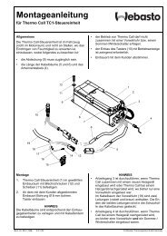
Operating Switches<br />
A Push/Pull switch, optional 99 Hour Digital Timer or a 7 Day<br />
Timer are available for the heater. All three are discussed on<br />
the following pages. Connect the operating switch as follows.<br />
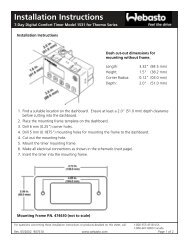
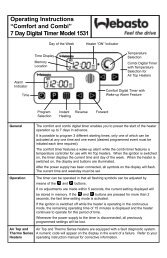
7 Day Timer<br />
The 7 Day Timer has been designed to provide a simple means<br />
to control the operation of the heater system and to include the<br />
capability for diagnostics. This timer connects to the diagnostic<br />
circuit of the heater. The timer then displays any heater fault<br />
codes in three digit number form automatically. The timer<br />
allows for pre-selection of turn on time, up to 7 days in<br />
advance, as well as an option for run times up to 2 hours<br />
before automatically turning off. In addition, there is an on/off<br />
switch for manual operation. By default the timer is pre-set by<br />
Espar to operate for two hours. Refer to instructions provided<br />
with timer for setting options.<br />
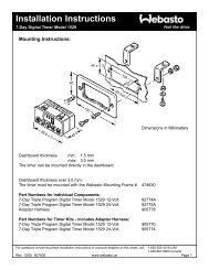
• Mount bezel into dash and insert timer or use Espar’s<br />
optional mounting bracket and secure to dash.<br />
• Use hardware supplied for connections.<br />
• Connect the switch harness to the connector at the heater<br />
and run harness to switch location. (Harness should be<br />
neatly routed and secured under dashboard).<br />
• Cut harness to length and terminate wires. Attach using<br />
connectors provided.<br />
• Refer to timer instructions for other wiring options.<br />
P/N CA1 00 135 (12v)<br />
P/N CA1 00 136 (24v)<br />
Mounting Bracket<br />
(optional)<br />
P/N CA0 <strong>10</strong> 061<br />
B e z e l<br />
P/N 25 1482 70 01 00<br />
a) Power from battery “+”<br />
b) Switch control to the heater<br />
c) Power from battery “-”<br />
d) Diagnostic from heater<br />
e) To the vehicle dimmer switch for light display<br />
f) To vehicle ignition accessories for continuos operation<br />
of heater<br />
g) Remote starter (optional)<br />
Note:<br />
If installing a remote starter, refer to remote<br />
starter instructions before terminating wires<br />
Note:<br />
Note:<br />
The timer display is automatically illuminated<br />
while the heater is operating. Connecting the<br />
grey wire to the vehicle dimmer switch will allow<br />
the timer display to illuminate with the vehicles<br />
dash lights.<br />
An alternative to connecting the black wire to the<br />
vehicle ignition accessories “On” circuit may also<br />
be considered for some applications where<br />
extended run times are desired. Connecting the<br />
black wire with the red wire will enable the heater<br />
to run continuously whether the heater is switched<br />
on manually or through the preset function.