7 Day Timer with Diagnostics Espar - T3-Infos
7 Day Timer with Diagnostics Espar - T3-Infos 7 Day Timer with Diagnostics Espar - T3-Infos
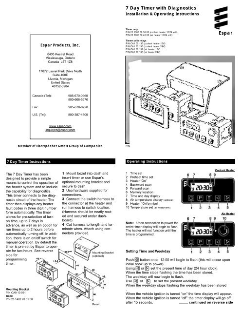
7 Day Timer with Diagnostics Installation & Operating Instructions Timer only P/N 22 1000 30 36 00 (coolant heater 12/24 volt) P/N 22 1000 30 40 00 (air heater 12/24 volt) Espar Espar Products, Inc. 6435 Kestrel Road Mississauga, Ontario Canada L5T 1Z8 Timers with relays P/N CA1 00 135 (coolant heater 12V) P/N CA1 00 136 (coolant heater 24V) P/N CA1 00 137 (air heater 12V) P/N CA1 00 138 (air heater 24V) 17672 Laurel Park Drive North Suite 400E Livonia, Michigan United States 48152-3984 Canada (Tel): 905-670-0960 800-668-5676 Fax: 905-670-0728 U.S. (Tel): 800-387-4800 www.espar.com inquiries@espar.com Member of Eberspächer GmbH Group of Companies P/N 603-104-0898 7 Day Timer Instructions Operating Instructions The 7 Day Timer has been designed to provide a simple means to control the operation of the heater system and to include the capability for diagnostics. This timer connects to the diagnostic circuit of the heater. The timer then displays any heater fault codes in three digit number form automatically. The timer allows for pre-selection of turn on time, up to 7 days in advance, as well as an option for run times up to 2 hours before automatically turning off. In addition, there is an on/off switch for manual operation. By default the timer is pre-set by Espar to operate for two hours. See reverse side for programming timer. Mounting Bracket P/N CA0 10 061 Bezel P/N 25 1482 70 01 00 1 Mount bezel into dash and insert timer or use Espar’s optional mounting bracket and secure to dash. 2 Use hardware supplied for connections. 3 Connect the switch harness to the connector at the heater and run harness to switch location. (Harness should be neatly routed and secured under dashboard). 4 Cut harness to length and terminate wires. Attach using connectors provided. Mounting Bracket (optional) Bezel 1 Time set 2 Preheat time set 3 Heater “On” 4 Backward scan 5 Forward scan 6 Memory location 7 Time and day display 8 Air temperature display (optional) 9 Heater “On”symbol 10 Temperature set (air heater only) Note: Upon connection to power the entire timer display will begin to flash. The heater will not function until the time is programmed. Setting Time and Weekday Coolant Heater Air Heater Push button once. 12:00 will begin to flash (this will occur upon initial hook up to power). Using or set the present time of day (24 hour clock). When the time stops flashing the time has been stored. The weekday will now begin to flash. Use or to set the present weekday. When the weekday stops flashing the weekday has been stored . When the vehicle ignition is turned “on” the time display will appear. When the vehicle ignition is turned “off” the timer display will go off after 15 seconds. ......... continued on reverse side
7 <strong>Day</strong> <strong>Timer</strong> <strong>with</strong> <strong>Diagnostics</strong><br />
Installation & Operating Instructions<br />
<strong>Timer</strong> only<br />
P/N 22 1000 30 36 00 (coolant heater 12/24 volt)<br />
P/N 22 1000 30 40 00 (air heater 12/24 volt)<br />
<strong>Espar</strong><br />
<strong>Espar</strong> Products, Inc.<br />
6435 Kestrel Road<br />
Mississauga, Ontario<br />
Canada L5T 1Z8<br />
<strong>Timer</strong>s <strong>with</strong> relays<br />
P/N CA1 00 135 (coolant heater 12V)<br />
P/N CA1 00 136 (coolant heater 24V)<br />
P/N CA1 00 137 (air heater 12V)<br />
P/N CA1 00 138 (air heater 24V)<br />
17672 Laurel Park Drive North<br />
Suite 400E<br />
Livonia, Michigan<br />
United States<br />
48152-3984<br />
Canada (Tel): 905-670-0960<br />
800-668-5676<br />
Fax: 905-670-0728<br />
U.S. (Tel): 800-387-4800<br />
www.espar.com<br />
inquiries@espar.com<br />
Member of Eberspächer GmbH Group of Companies<br />
P/N 603-104-0898<br />
7 <strong>Day</strong> <strong>Timer</strong> Instructions<br />
Operating Instructions<br />
The 7 <strong>Day</strong> <strong>Timer</strong> has been<br />
designed to provide a simple<br />
means to control the operation of<br />
the heater system and to include<br />
the capability for diagnostics.<br />
This timer connects to the diagnostic<br />
circuit of the heater. The<br />
timer then displays any heater<br />
fault codes in three digit number<br />
form automatically. The timer<br />
allows for pre-selection of turn<br />
on time, up to 7 days in<br />
advance, as well as an option for<br />
run times up to 2 hours before<br />
automatically turning off. In addition,<br />
there is an on/off switch for<br />
manual operation. By default the<br />
timer is pre-set by <strong>Espar</strong> to operate<br />
for two hours. See reverse<br />
side for<br />
programming<br />
timer.<br />
Mounting Bracket<br />
P/N CA0 10 061<br />
Bezel<br />
P/N 25 1482 70 01 00<br />
1 Mount bezel into dash and<br />
insert timer or use <strong>Espar</strong>’s<br />
optional mounting bracket and<br />
secure to dash.<br />
2 Use hardware supplied for<br />
connections.<br />
3 Connect the switch harness to<br />
the connector at the heater and<br />
run harness to switch location.<br />
(Harness should be neatly routed<br />
and secured under dashboard).<br />
4 Cut harness to length and terminate<br />
wires. Attach using connectors<br />
provided.<br />
Mounting Bracket<br />
(optional)<br />
Bezel<br />
1 Time set<br />
2 Preheat time set<br />
3 Heater “On”<br />
4 Backward scan<br />
5 Forward scan<br />
6 Memory location<br />
7 Time and day display<br />
8 Air temperature display (optional)<br />
9 Heater “On”symbol<br />
10 Temperature set (air heater only)<br />
Note: Upon connection to power the<br />
entire timer display will begin to flash.<br />
The heater will not function until the<br />
time is programmed.<br />
Setting Time and Weekday<br />
Coolant Heater<br />
Air Heater<br />
Push button once. 12:00 will begin to flash (this will occur upon<br />
initial hook up to power).<br />
Using or set the present time of day (24 hour clock).<br />
When the time stops flashing the time has been stored.<br />
The weekday will now begin to flash.<br />
Use or to set the present weekday.<br />
When the weekday stops flashing the weekday has been stored<br />
.<br />
When the vehicle ignition is turned “on” the time display will appear.<br />
When the vehicle ignition is turned “off” the timer display will go off<br />
after 15 seconds.<br />
......... continued on reverse side
Operating Instructions<br />
Changing the Time or <strong>Day</strong><br />
Push and hold button until the time display begins to flash.<br />
Continue to set the time as listed in setting time and weekday.<br />
Using the <strong>Timer</strong> <strong>with</strong> the Vehicle Ignition “Off”<br />
Push button.<br />
will appear on the display as well as the operation countdown timer.<br />
The running time is factory set to a maximum of 120 minutes. This<br />
running time can be reset once or permanently as desired.<br />
Adjusting Preheat Time Once<br />
To Use Preset Start Times<br />
Press the button until the desired memory location<br />
appears in the display.<br />
The heater will start at the day and time displayed.<br />
The display will go off in 15 seconds. The memory location<br />
number will stay displayed (1, 2 or 3).<br />
To Turn Heater “Off” - All Modes<br />
Press the button once.<br />
The heat signal to the heater will be turned “off”.<br />
The heater will do a normal cooldown and turn itself “off”.<br />
<strong>Espar</strong><br />
Press button.<br />
The will appear in the display and the preselected run time will<br />
appear in the display (maximum time of 120 minutes).<br />
Use the or to adjust the desired run time.<br />
Adjusting the Heater Preheat Time Permanently<br />
(Maximum Preheat Time of 120 minutes)<br />
Push and hold (about 3 seconds) until the display lights up and<br />
flashes. Release button.<br />
Use or to set the new fixed preheat time.<br />
When the display goes off the new preheat time is set.<br />
Note: At the end of a preheat cycle the timer will turn the heater off.<br />
The heater will complete a cool down cycle and turn itself off.<br />
Using the Heater Manually <strong>with</strong> the Vehicle Accessory “On”<br />
Push button.<br />
The symbol will appear in the display next to the time of day.<br />
The time of day will remain displayed during ignition on operation.<br />
The heater will function continually as long as the vehicle ignition is “ o n ”.<br />
When the vehicle ignition is turned “off” the heater will continue to<br />
operate for an addtional 15 minutes.<br />
The run time can be altered by pressing the or buttons.<br />
The heater can be turned off by pressing button.<br />
Set Preheat Times into Memory<br />
Press button until the desired memory location is shown in the<br />
display (Three memory locations are available).<br />
Using the or buttons set the desired preheat start time of day.<br />
When the time stops flashing the time of day is set.<br />
Using the or buttons set the desired day of the week.<br />
When the day of the week stops flashing the day is set.<br />
Coolant Heater <strong>Timer</strong> Connections<br />
Note: When the vehicle ignition is turned “on” the time of day and day of the<br />
week will appear in the timer display. This will stay on as long as the vehicle<br />
ignition is “on”.<br />
Note: When the vehicle lights are turned “on” the timer backlight will come<br />
“on”also.<br />
Note: This timer is equipped to display fault code numbers if the heater<br />
should shut down due to an operating fault.The fault code will show in the<br />
timer display next to the flashing heat wave symbol.This applies whenever<br />
the timer is used in conjunction <strong>with</strong> the Hydronic heaters, the D7W model 25<br />
1807, the D9W and the D12W models 25 1859 and 25 1860, and has the<br />
blue diagnostic wire connected.<br />
Note: If the timer is purchased <strong>with</strong>out the harness kit, ensure a load relay<br />
is installed for heaters where the switch wire carries a load (i.e. fuel metering<br />
pump or solenoid valve). This affects the current models for D8LC, D7W,<br />
D12W, D24W and D30W heaters.<br />
Note:<br />
An outside temperature sensor is available as an option<br />
Wiring Connections at connector<br />
Terminal 1 Power from vehicle dash lights<br />
Terminal 2 Heater switch wire - yellow wire<br />
Terminal 4 Connect to vehicle ground<br />
Terminal 6 Temperature setting “+” (air only)<br />
Terminal 8 Heater diagnostic lead - blue wire<br />
Terminal 9 Temperature setting “-” (air only)<br />
Terminal 10 To vehicle “ACC”accessory for continuous overnight use<br />
Terminal 11 Positive power from heater - red “+”<br />
Terminal 12 Ground lead from heater - brown “-”<br />
Terminal 3,5,7 Left blank, not required<br />
Air Heater <strong>Timer</strong> Connectionsa<br />
a) Power from battery”+”<br />
b) Switch control to heater<br />
c) Power from battery”-”<br />
d) <strong>Diagnostics</strong> from heater<br />
e) To vehicle dimmer switch for light display<br />
f) To vehicle ignition accessories for continuous<br />
operation of heater<br />
a) Power from battery ”+”<br />
b) Switch control to heater<br />
c) Power from battery ”-”<br />
d) <strong>Diagnostics</strong> from heater<br />
e) Temperature setting “+”<br />
f) Temperature setting “-”<br />
g) To vehicle dimmer switch for light display<br />
h) To vehicle ignition accessories for continuous operation of heater


