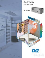
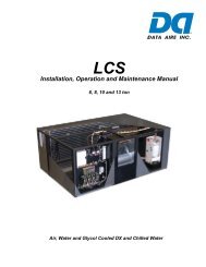
Installation, Operation and Maintenance Manual - Data Aire
Installation, Operation and Maintenance Manual - Data Aire
Installation, Operation and Maintenance Manual - Data Aire

You also want an ePaper? Increase the reach of your titles
YUMPU automatically turns print PDFs into web optimized ePapers that Google loves.
2.0 PIPING<br />
2.1 Split Air Cooled Unit Piping<br />
Refer to the attached line sizing chart on page 36 for a guideline for sizing refrigerant lines. The<br />
ultimate responsibility for line sizing selection is that of the installing contractor or the project engineer.<br />
<strong>Data</strong> <strong>Aire</strong> does not assume this responsibility. The chart covers distances up to 200 equivalent<br />
feet. For installations greater than this distance, consult ASHRAE or similar references.<br />
St<strong>and</strong>ard piping practices must be used to ensure proper oil return <strong>and</strong> effi cient operation. The<br />
interconnecting lines to the remote air cooled condenser or condensing unit must be installed by a<br />
qualifi ed refrigeration mechanic.<br />
2.1.1 Discharge Lines<br />
Discharge lines, also called hot gas lines, should be trapped at the top (inverted) <strong>and</strong> bottom, as<br />
well as every 15 to 20 feet of vertical rise. Discharge line check valves are recommended on all<br />
installations, especially those where there are long pipe runs or cold climate. Check valves should<br />
be installed 6 to 10 feet from the compressor. The discharge, suction <strong>and</strong> liquid lines need to<br />
be refrigerant grade copper <strong>and</strong> in accordance with local code. All refrigeration piping should be<br />
installed with high temperature brazed joints. When brazing, a supply of nitrogen gas needs to be<br />
fed through the refrigerant lines. Be sure to open the other end of the refrigerant line to allow the<br />
nitrogen to bleed off <strong>and</strong> not pressurize the piping. Prevailing good refrigeration practices should<br />
be employed for piping support, leak testing, dehydration <strong>and</strong> charging of the refrigerant circuits.<br />
During the installation the lines should be capped off <strong>and</strong> fi lled with dry nitrogen at the end of each<br />
day’s work or until the system is completed <strong>and</strong> sealed.<br />
<strong>Data</strong> <strong>Aire</strong> recommends a silver/phosphorus/copper alloy with 5 to 15% silver to be used to braze<br />
the refrigerant line sets to the indoor <strong>and</strong> outdoor units. Nitrogen needs to be fl owing through the<br />
lines to eliminate carbon deposit build-up of the joints. Carbon could contaminate the refrigerant<br />
<strong>and</strong> restrict the metering device.<br />
Piping must be supported within 18” of the inlet <strong>and</strong> outlet connections. The inlet connection is<br />
located on the top header of all units. The discharge outlet is located at the bottom of the header.<br />
The discharge line pressure drop should not exceed 6 PSIG for R-407C <strong>and</strong> 9 PSIG for R-410A.<br />
Recommended gas velocity for proper oil return is 1,000 FPM. Slope horizontal lines downward in<br />
the direction of refrigerant fl ow, 1/2” for every 10 feet of line length. Discharge lines do not require<br />
insulation but due to the high temperatures of the refrigerant inside the line, the pipes may be<br />
insulated to protect against burns to individuals near or around the lines.<br />
2.1.2 Liquid Lines<br />
Liquid lines are determined by pressure drop <strong>and</strong> velocity. The liquid line pressure drop for R-<br />
407C should not exceed 5 PSIG. For systems with R-410A, the pressure drop should not exceed<br />
9 PSIG. The recommended velocity should be between 200 <strong>and</strong> 300 FPM. To avoid excessive<br />
10