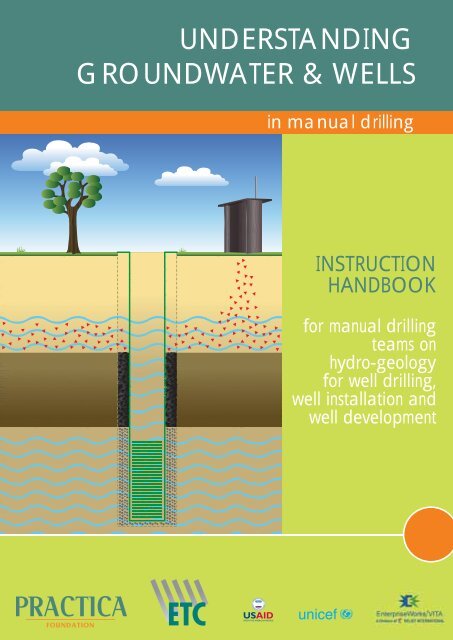
Understanding Groundwater & Wells in manual drilling PRACTICA
Understanding Groundwater & Wells in manual drilling PRACTICA
Understanding Groundwater & Wells in manual drilling PRACTICA

Create successful ePaper yourself
Turn your PDF publications into a flip-book with our unique Google optimized e-Paper software.
UNDERSTANDING<br />
GROUNDWATER & WELLS<br />
<strong>in</strong> <strong>manual</strong> drill<strong>in</strong>g<br />
INSTRUCTION<br />
HANDBOOK<br />
for <strong>manual</strong> drill<strong>in</strong>g<br />
teams on<br />
hydro-geology<br />
for well drill<strong>in</strong>g,<br />
well <strong>in</strong>stallation and<br />
well development
UNDERSTANDING<br />
GROUNDWATER & WELLS<br />
<strong>in</strong> <strong>manual</strong> drill<strong>in</strong>g<br />
Instruction handbook for <strong>manual</strong> drill<strong>in</strong>g teams<br />
on hydro-geology for well drill<strong>in</strong>g,<br />
well <strong>in</strong>stallation and well development<br />
Published by the <strong>PRACTICA</strong> Foundation<br />
Author – Arjen van der Wal<br />
Peer read<strong>in</strong>g – Richard C. Carter<br />
Structural support – Wouter Jan Fell<strong>in</strong>ga , Melanie Stallen<br />
French translation – Julien Labas, Stéphan Abric, Régis Garandeau<br />
Swahili translation – Walter Mg<strong>in</strong>a, Ester Mg<strong>in</strong>a-van Vugt<br />
Illustrations – Franck Nederstigt<br />
Photos – Arjen van der Wal<br />
Layout – Marijke Kreikamp/ 4colour design<br />
First edition – April 2008<br />
Second edition – June 2010<br />
<strong>PRACTICA</strong> Foundation develops and dissem<strong>in</strong>ates low-cost appropriate technology <strong>in</strong> water and renewable energy <strong>in</strong><br />
develop<strong>in</strong>g countries. We focus on technology that responds to local cultural contexts, can be locally produced and<br />
ma<strong>in</strong>ta<strong>in</strong>ed, and supports exist<strong>in</strong>g markets.<br />
<strong>PRACTICA</strong> foundation<br />
Ooste<strong>in</strong>d 47 - NL-3356 AB Papendrecht - The Netherlands<br />
(t) +31(0)786150125<br />
<strong>in</strong>fo@practicafoundation.nl<br />
www.practicafoundation.nl<br />
<strong>PRACTICA</strong> Foundation - Manual drill<strong>in</strong>g series
Disclaimer<br />
This <strong>manual</strong> is free of charge. Any parts of this <strong>in</strong>struction<br />
<strong>manual</strong>, <strong>in</strong>clud<strong>in</strong>g the illustrations and technical draw<strong>in</strong>gs<br />
may be copied to meet local needs, without permission<br />
from the author or publisher, provided the parts are<br />
distributed free, not for profit and reference to the<br />
source is made. The author would appreciate receiv<strong>in</strong>g<br />
notice and a copy of any materials <strong>in</strong> which orig<strong>in</strong>al text<br />
or pictures have been used. For any reproduction with<br />
commercial ends, written permission must be obta<strong>in</strong>ed <strong>in</strong><br />
advance from the <strong>PRACTICA</strong> Foundation.<br />
This <strong>in</strong>struction <strong>manual</strong> is available <strong>in</strong> English and <strong>in</strong> French<br />
and Swahili and has been developed for use <strong>in</strong> technical<br />
tra<strong>in</strong><strong>in</strong>g courses organised for the <strong>in</strong>tended users. In case<br />
you want to organize such tra<strong>in</strong><strong>in</strong>g, you may contact<br />
the <strong>PRACTICA</strong> Foundation for further <strong>in</strong>formation and<br />
support.<br />
The first edition of this publication was made possible<br />
by a f<strong>in</strong>ancial contribution from the Technical Tra<strong>in</strong><strong>in</strong>g<br />
Programme of the ETC Foundation <strong>in</strong> the Netherlands and<br />
the United Nations Children’s Fund - UNICEF - office <strong>in</strong><br />
Chad. An updated version of this publication (the second<br />
edition) was made possible by a f<strong>in</strong>ancial contribution from<br />
the United States Agency for International Development<br />
(USAID) as part of the West Africa Water Initiative<br />
(WAWI).<br />
The United Nations International Children’s Fund<br />
(UNICEF), <strong>PRACTICA</strong> Foundation and Enterprise<br />
Works/Vita have developed a toolkit for African<br />
countries wish<strong>in</strong>g to embark on the professionalization<br />
of <strong>manual</strong> drill<strong>in</strong>g. This toolkit <strong>in</strong>cludes Technical<br />
Notes, Technical Manuals <strong>in</strong>clud<strong>in</strong>g this publication,<br />
Advocacy Materials, Mapp<strong>in</strong>g of suitable areas for<br />
<strong>manual</strong> drill<strong>in</strong>g, Case Studies, and Implementation and<br />
Tra<strong>in</strong><strong>in</strong>g Manuals. This <strong>in</strong>itiative builds the capacity of<br />
the local private sector <strong>in</strong> order to respond to the ever<br />
<strong>in</strong>creas<strong>in</strong>g demand for safe water <strong>in</strong> rural areas.<br />
The Technical Tra<strong>in</strong><strong>in</strong>g Program (TTP) of the ETC Foundation<br />
contributed with structural support <strong>in</strong> the educational<br />
aspects of this <strong>manual</strong>.<br />
While every care has been taken to ensure accuracy of<br />
the <strong>in</strong>formation given <strong>in</strong> this <strong>manual</strong>, neither the publisher(s)<br />
nor the author(s) can be held responsible for any damage<br />
result<strong>in</strong>g from the application of the described methods.<br />
Any liability <strong>in</strong> this respect is excluded.<br />
Note to those consider<strong>in</strong>g translation or modification; before beg<strong>in</strong>n<strong>in</strong>g any translation or modification and <strong>in</strong> order to<br />
avoid duplication of efforts and un<strong>in</strong>tended mistakes, please contact the <strong>PRACTICA</strong> Foundation. This document or parts of this<br />
document may not be copied or published under a new name or author without permission from <strong>PRACTICA</strong> Foundation.<br />
<strong>PRACTICA</strong> Foundation - Manual drill<strong>in</strong>g series
Foreword<br />
Context<br />
Over the years much literature on geology, hydrogeology<br />
and hygienic aspects has been written and <strong>in</strong> a lot of<br />
countries this <strong>in</strong>formation is used by policy makers, project<br />
managers, eng<strong>in</strong>eers and technicians to construct mach<strong>in</strong>edrilled<br />
wells <strong>in</strong> their countries.<br />
Mach<strong>in</strong>e-drilled wells are often very expensive and not<br />
affordable by large parts of the population <strong>in</strong> develop<strong>in</strong>g<br />
countries. Another option is to drill ‘shallow’ water wells<br />
(up to about 35 meter depth) by hand, so reduc<strong>in</strong>g the price<br />
of a well by a factor 4 -10 compared to a mach<strong>in</strong>e-drilled<br />
borehole. This cost reduction not only enables NGOs<br />
and Governments to construct more water wells, but also<br />
‘opens the door’ to villagers, farmers, schools and small<br />
communities to have a well constructed <strong>in</strong>dependently<br />
through the private sector.<br />
Although most of the exist<strong>in</strong>g <strong>manual</strong> drill<strong>in</strong>g enterprises<br />
are technically able to drill boreholes, mistakes are easily<br />
made dur<strong>in</strong>g the construction and development of the wells.<br />
Furthermore good well construction alone does not<br />
ensure good water quality and susta<strong>in</strong>ed yield from the<br />
well over many years. In order to achieve that, know-how<br />
on geology and groundwater is important.<br />
However, many technical workers of <strong>manual</strong> drill<strong>in</strong>g<br />
enterprises may have limited education. Much of the<br />
available literature on geology, hydrogeology and<br />
hygiene cannot easily be understood without an advanced<br />
education.<br />
Technical workers are used to learn through experience<br />
and repetition. Of course tra<strong>in</strong><strong>in</strong>g could be given to<br />
these workers but classroom tra<strong>in</strong><strong>in</strong>g alone is known to<br />
be <strong>in</strong>sufficient for drill<strong>in</strong>g teams. They need to relate<br />
theoretical <strong>in</strong>formation to the real practical problems<br />
which occur regularly while work<strong>in</strong>g on drill<strong>in</strong>g sites.<br />
This book therefore only deals with those essential subjects<br />
which are relevant to <strong>manual</strong> drill<strong>in</strong>g and well <strong>in</strong>stallation<br />
<strong>in</strong> practice, <strong>in</strong> simple and understandable language.*<br />
*Note<br />
Technical terms and the way <strong>in</strong> which subjects are expla<strong>in</strong>ed are based on the average expected educational level of<br />
the <strong>in</strong>tended users. Sometimes, the use of complicated geological and technical terms has been avoided to create better<br />
understand<strong>in</strong>g. Some words (for example ‘soil’ or ‘gravel pack’) have been used because they are known by the <strong>in</strong>tended<br />
users, although these words are not always the terms that are used by geologists. Please keep <strong>in</strong> m<strong>in</strong>d that the objective of the<br />
handbook is to create better understand<strong>in</strong>g of well drill<strong>in</strong>g <strong>in</strong> practice, aimed at technical workers of <strong>manual</strong> drill<strong>in</strong>g teams<br />
who may have a limited educational background.<br />
READERSHIP<br />
This handbook can be used as a guide dur<strong>in</strong>g tra<strong>in</strong><strong>in</strong>g sessions for well drillers, local tra<strong>in</strong>ers and quality controllers. It also<br />
serves as a reference for drill<strong>in</strong>g supervisors, NGOs, development agencies, <strong>manual</strong> drill<strong>in</strong>g teams and enterprises dur<strong>in</strong>g the<br />
entire drill<strong>in</strong>g process. The handbook consists of three sections that can be read together, or used and pr<strong>in</strong>ted separately<br />
for the various target groups.<br />
<strong>PRACTICA</strong> Foundation - Manual drill<strong>in</strong>g series
Colophon<br />
AVAILABLE MANUALS IN THIS SERIES:<br />
Technical tra<strong>in</strong><strong>in</strong>g handbooks on affordable <strong>manual</strong> well drill<strong>in</strong>g.<br />
These practical handbooks create awareness of <strong>manual</strong> drill<strong>in</strong>g for affordable water supply and a roadmap for implementation<br />
of <strong>manual</strong> drill<strong>in</strong>g programs. The <strong>manual</strong>s provide an extensive and detailed guide for tra<strong>in</strong>ers and drill<strong>in</strong>g teams <strong>in</strong> the use<br />
of various drill<strong>in</strong>g techniques for mak<strong>in</strong>g affordable boreholes. The techniques are expla<strong>in</strong>ed <strong>in</strong> simple and understandable<br />
language, us<strong>in</strong>g clear illustrations and draw<strong>in</strong>gs.<br />
JETTING<br />
Manual drill<strong>in</strong>g series<br />
TECHNICAL TRAINING<br />
HANDBOOK ON<br />
AFFORDABLE MANUAL<br />
WELL DRILLING<br />
1. Manual drill<strong>in</strong>g series: JETTING<br />
This handbook describes <strong>in</strong> detail the various jett<strong>in</strong>g techniques that can be used to drill wells <strong>in</strong><br />
loose and soft soil formations. With this technique, wells are drilled <strong>in</strong> a number of hours rather<br />
than days.<br />
PERCUSSION<br />
Manual drill<strong>in</strong>g series<br />
TECHNICAL TRAINING<br />
HANDBOOK ON<br />
AFFORDABLE MANUAL<br />
WELL DRILLING<br />
2. Manual drill<strong>in</strong>g series: PERCUSSION<br />
This handbook describes <strong>in</strong> detail the percussion technique. Although the technique is slower<br />
than other drill<strong>in</strong>g techniques, it is the only <strong>manual</strong> drill<strong>in</strong>g technique that is able to drill through<br />
consolidated rock layers.<br />
AUGERING<br />
Manual drill<strong>in</strong>g series<br />
TECHNICAL TRAINING<br />
HANDBOOK ON<br />
AFFORDABLE MANUAL<br />
WELL DRILLING<br />
3. Manual drill<strong>in</strong>g series: HAND AUGER<br />
This handbook describes the hand auger technique. This cheap and effective technique is very<br />
suitable for s<strong>in</strong>k<strong>in</strong>g shallow wells <strong>in</strong> soft soils and is excellent for soil surveys. Many drill<strong>in</strong>g teams<br />
have this technique <strong>in</strong> their toolkit to complement other drill<strong>in</strong>g techniques.<br />
SLUDGING<br />
Manual drill<strong>in</strong>g series<br />
TECHNICAL TRAINING<br />
HANDBOOK ON<br />
AFFORDABLE MANUAL<br />
WELL DRILLING<br />
4. Manual drill<strong>in</strong>g series: SLUDGING<br />
This handbook describes the sludg<strong>in</strong>g technique, and <strong>in</strong> greater detail the ROTA-sludge technique.<br />
It is a comb<strong>in</strong>ation of sludg<strong>in</strong>g and percussion and is particularly useful due to its versatile<br />
application for a range of soil formations.<br />
UNDERSTANDING<br />
GROUNDWATER & WELLS<br />
<strong>in</strong> <strong>manual</strong> drill<strong>in</strong>g<br />
INSTRUCTION<br />
HANDBOOK<br />
for <strong>manual</strong> drill<strong>in</strong>g<br />
teams on<br />
hydro-geology<br />
for well drill<strong>in</strong>g,<br />
well <strong>in</strong>stallation and<br />
well development<br />
5. Manual: ‘<strong>Understand<strong>in</strong>g</strong> <strong>Groundwater</strong> and <strong>Wells</strong> <strong>in</strong> <strong>manual</strong> drill<strong>in</strong>g’<br />
The <strong>manual</strong> ‘<strong>Understand<strong>in</strong>g</strong> <strong>Groundwater</strong> & <strong>Wells</strong> <strong>in</strong> <strong>manual</strong> drill<strong>in</strong>g’ complements the 4 technical<br />
tra<strong>in</strong><strong>in</strong>g handbooks and highlights those essential subjects which are relevant to <strong>manual</strong> drill<strong>in</strong>g,<br />
geo-hydrology, hygiene, well <strong>in</strong>stallation and well development <strong>in</strong> practice, <strong>in</strong> simple and<br />
understandable language.<br />
<strong>PRACTICA</strong> Foundation - Manual drill<strong>in</strong>g series
Table of contents<br />
Introduction 2<br />
Mak<strong>in</strong>g a well 2<br />
The Manual 2<br />
Additional <strong>in</strong>formation 2<br />
1 BASIC GEOLOGY 3<br />
1.1 Geology 3<br />
1.2 Manual drill<strong>in</strong>g techniques 3<br />
Hand augers 4<br />
Sludge / Rota sludge 4<br />
Jett<strong>in</strong>g 5<br />
Percussion and bailer 5<br />
other techniques 5<br />
1.3 Soil classification and determ<strong>in</strong>ation 6<br />
Permeability 6<br />
Field ‘tricks’ 7<br />
Porosity 7<br />
Turbidity 8<br />
2 HYDROLOGY 9<br />
2.1 Hydrology 9<br />
2.2 <strong>Groundwater</strong> flow 9<br />
2.3 Aquifers 10<br />
2.4 Sea water <strong>in</strong>trusion 11<br />
2.5 Salt, iron and m<strong>in</strong>erals 11<br />
3 HYGIENE IN RELATION TO<br />
GEOLOGY 13<br />
3.1 Site selection 13<br />
Latr<strong>in</strong>es 13<br />
Waste (dump) areas, fi re places<br />
and fuel stations 13<br />
Sun or shade 13<br />
3.2 Migration of pathogens<br />
(bacteria) 14<br />
Diff erent aquifers 14<br />
One aquifer 14<br />
3.3 Sanitary seal 14<br />
4 DRILLING LOGS 16<br />
4.1 Why drill<strong>in</strong>g logs 16<br />
4.2 Tak<strong>in</strong>g soil samples 16<br />
4.3 Drill<strong>in</strong>g depths 16<br />
4.4 Fill<strong>in</strong>g <strong>in</strong> the drill<strong>in</strong>g logs 17<br />
4.5 Determ<strong>in</strong>e the depth of the<br />
filter screen and backfill<strong>in</strong>g 19<br />
Well-screen, position and length 19<br />
Sump 19<br />
Thickness of the gravel pack 19<br />
Thickness of the sanitary seal 20<br />
Cutt<strong>in</strong>gs 20<br />
Sanitary top-seal 20<br />
5 WATER PRESSURE AND DRILLING<br />
FLUIDS 21<br />
5.1 Drill<strong>in</strong>g with water pressure 21<br />
Temporary cas<strong>in</strong>g 21<br />
Water pressure 21<br />
Borehole 22<br />
5.2 Drill fluid additives 23<br />
Bentonite 23<br />
Other natural clays 23<br />
Polymers 23<br />
Fresh cow-dung 24<br />
Fibers and other solids 24<br />
5.3 Removal of additives from<br />
the borehole 24<br />
6 WELL CONSTRUCTION 25<br />
6.1 Well design 25<br />
Borehole diameter 25<br />
Borehole depth 25<br />
Completion of the borehole 25<br />
Measur<strong>in</strong>g tools 25<br />
<strong>PRACTICA</strong> Foundation - Manual drill<strong>in</strong>g series
6.2 Materials: PVC well-screen and cas<strong>in</strong>g 26<br />
Diameter and wall thickness of<br />
well cas<strong>in</strong>g 26<br />
Slots 26<br />
Sump 27<br />
Pipe jo<strong>in</strong>ts 27<br />
APPENDIX 41<br />
A Country specific regulations 41<br />
B Country specific geological conditions 41<br />
C Drill<strong>in</strong>g logs 41<br />
D Test pump<strong>in</strong>g form 41<br />
E Chlor<strong>in</strong>ation 41<br />
6.3 Materials: Gravel pack 27<br />
6.4 Materials: Sanitary seal 28<br />
6.5 Well construction 28<br />
7 WELL DEVELOPMENT AND TESTING 31<br />
7.1 Welldevelopment 31<br />
Surge block or plunger 31<br />
Discont<strong>in</strong>uous pump<strong>in</strong>g<br />
(start-stop cycle pump<strong>in</strong>g) 32<br />
Pumps for well development 32<br />
Re-development 32<br />
7.2 Pump<strong>in</strong>g test – Well yield 33<br />
Dip tape 33<br />
Yield test with motorized or deep<br />
well pumps 33<br />
Yield test with hand pumps 34<br />
Water level measur<strong>in</strong>g tape or<br />
measur<strong>in</strong>g rope 34<br />
7.3 Water quality test<strong>in</strong>g 35<br />
Representative water samples 35<br />
Well dis<strong>in</strong>fection – chlor<strong>in</strong>ation 35<br />
8 FINALIZATION 36<br />
8.1 Concrete slab/apron 36<br />
8.2 Soak pit 36<br />
8.3 Pump choice 36<br />
GLOSSARY OF TERMS 37<br />
ACKNOWLEDGEMENTS 40<br />
<strong>PRACTICA</strong> Foundation - Manual drill<strong>in</strong>g series
<strong>Understand<strong>in</strong>g</strong> <strong>Groundwater</strong> & <strong>Wells</strong> <strong>in</strong> <strong>manual</strong> drill<strong>in</strong>g<br />
INTRODUCTION<br />
MAKING A WELL<br />
The construction of a well, us<strong>in</strong>g <strong>manual</strong> drill<strong>in</strong>g techniques is a complicated process. Before drill<strong>in</strong>g starts a good drill<strong>in</strong>g<br />
site has to be selected, where experience suggests that there will be an adequate quantity of good quality groundwater.<br />
Dur<strong>in</strong>g the drill<strong>in</strong>g process there are a lot of different aspects which require attention to prevent th<strong>in</strong>gs from go<strong>in</strong>g wrong.<br />
Besides the practical drill<strong>in</strong>g skills which are executed at ground level, at the same time attention has to be paid to important<br />
processes which are happen<strong>in</strong>g below ground level dur<strong>in</strong>g drill<strong>in</strong>g. Water used <strong>in</strong> drill<strong>in</strong>g (work<strong>in</strong>g water) could flow away<br />
or worse; the borehole could collapse, bury<strong>in</strong>g part of the drill<strong>in</strong>g equipment. And f<strong>in</strong>ally, once the hole has been drilled, the<br />
well cas<strong>in</strong>g, screen and sanitary seals have to be <strong>in</strong>stalled at the right depth, prevent<strong>in</strong>g contam<strong>in</strong>ated water from enter<strong>in</strong>g,<br />
and ensur<strong>in</strong>g a sufficient yield.<br />
In many countries <strong>manual</strong> drill<strong>in</strong>g teams experience problems with site selection, loss of work<strong>in</strong>g water, soil determ<strong>in</strong>ation,<br />
logg<strong>in</strong>g, well <strong>in</strong>stallation, well development, water quality and well yield (flow rate of the well). These problems may occur<br />
when the drill<strong>in</strong>g process is not completely understood and important steps are missed.<br />
This <strong>in</strong>struction <strong>manual</strong> describes many of the subjects and problems which you may come across dur<strong>in</strong>g drill<strong>in</strong>g. The <strong>manual</strong><br />
will help you to understand the drill<strong>in</strong>g process at ground level and far below ground level <strong>in</strong> the drilled hole. With the<br />
<strong>in</strong>formation provided you will be able to understand what is tak<strong>in</strong>g place <strong>in</strong> the hole dur<strong>in</strong>g drill<strong>in</strong>g, and perform a professional<br />
job as you construct high quality water wells.<br />
THE MANUAL<br />
How does this <strong>in</strong>struction <strong>manual</strong> work? In the table of contents (see previous page) an overview is given of the subjects and<br />
where to f<strong>in</strong>d them.<br />
Chapter 1 to chapter 8 conta<strong>in</strong>s all the <strong>in</strong>formation needed for a good understand<strong>in</strong>g of the drill<strong>in</strong>g process and correct well<br />
<strong>in</strong>stallation. In the Appendix you will f<strong>in</strong>d country specific regulations. These are regulations designed for communal wells<br />
and def<strong>in</strong>ed by the government or NGO you are work<strong>in</strong>g for. In the Appendix you will also f<strong>in</strong>d some specific geological<br />
conditions, which are unique for the area or country you work <strong>in</strong>. Furthermore, simple ‘blank’ drill<strong>in</strong>g logs are <strong>in</strong>cluded, which<br />
can be copied for use <strong>in</strong> the field.<br />
ADDITIONAL INFORMATION<br />
For more detailed background <strong>in</strong>formation for policy makers, project managers, implement<strong>in</strong>g NGOs, tra<strong>in</strong>ers and supervisors,<br />
some useful titles of exist<strong>in</strong>g books and <strong>manual</strong>s are given at the end of this <strong>in</strong>struction <strong>manual</strong>.<br />
2<br />
<strong>PRACTICA</strong> Foundation - Manual drill<strong>in</strong>g series
<strong>Understand<strong>in</strong>g</strong> <strong>Groundwater</strong> & <strong>Wells</strong> <strong>in</strong> <strong>manual</strong> drill<strong>in</strong>g<br />
1 BASIC GEOLOGY<br />
1.1 GEOLOGY<br />
Geology is the study of the earth. It describes the orig<strong>in</strong>s and formation of the rock types under the surface of the earth. The<br />
orig<strong>in</strong>al material or “build<strong>in</strong>g blocks” of the earth are the hard rocks such as granites and volcanic formations, formed when<br />
molten material cooled beneath or at the surface of the earth. These are known as the igneous rocks (“made by fire”). It is<br />
from these rocks that sedimentary layers have been formed.<br />
Sedimentary layers are formed by the weather<strong>in</strong>g, transport (by w<strong>in</strong>d or rivers) and deposition (sediment) of particles broken<br />
down from rocks. Those particles can range <strong>in</strong> size from extremely f<strong>in</strong>e (clay particles) through silt-sized to the larger sand<br />
and gravel particles. Sedimentary layers may be unconsolidated (loose such as clay and sand) or consolidated (cemented<br />
together) to form harder rocks such as sandstones and lime stones.<br />
Some examples:<br />
The clay particles of the clay layer that you have encountered dur<strong>in</strong>g drill<strong>in</strong>g may have arrived from somewhere else. The clay<br />
particles were formed by the weather<strong>in</strong>g of rocks. Then they may have been eroded and transported to your drill<strong>in</strong>g location<br />
by a river or the sea. F<strong>in</strong>ally the clay particles were deposited (sediment, settled down) <strong>in</strong> still water, for example a lake.<br />
In the same way a sand or gravel layer could have been deposited. The sand and gravel particles may have been transported<br />
by a river and were deposited along the river bed. Although now there may not be a river or a lake present, the deposition<br />
of particles could have happened thousands or even millions of years ago. Another way to transport particles is by w<strong>in</strong>d.<br />
Particles can be blown to another location by the w<strong>in</strong>d.<br />
When a mixture of sand and f<strong>in</strong>e particles has been compacted by pressure, created by the weight of layers on top of it and<br />
cemented by m<strong>in</strong>erals present <strong>in</strong> the mixture, sandstone is created. Sandstone is hard and may look like solid stone, but is <strong>in</strong> fact<br />
consolidated sediment and may be possible to drill through.<br />
These are just some basic examples. It goes too far to describe the deposition of all sedimentary layers <strong>in</strong> detail. The<br />
sedimentary surface layers of the earth are most important to <strong>manual</strong> drillers. Especially hard layers such as sandstone,<br />
compacted clay, fragments of un-weathered rock and laterite pose challenges to <strong>manual</strong> drill<strong>in</strong>g because of their hardness.<br />
1.2 MANUAL DRILLING TECHNIQUES<br />
To drill through all these different types of formation (soil) a whole range of different <strong>manual</strong> drill<strong>in</strong>g techniques have been<br />
developed and used around the world. In each case the drill<strong>in</strong>g technique must (a) break or cut the formation, (b) remove the<br />
cut material (the soil) from the hole, and (c) if necessary provide support to the walls of the hole, to prevent collapse dur<strong>in</strong>g<br />
drill<strong>in</strong>g. A short overview of techniques;<br />
<strong>PRACTICA</strong> Foundation - Manual drill<strong>in</strong>g series 3
<strong>Understand<strong>in</strong>g</strong> <strong>Groundwater</strong> & <strong>Wells</strong> <strong>in</strong> <strong>manual</strong> drill<strong>in</strong>g<br />
THE HAND AUGER consists of extendable steel rods, rotated<br />
by a handle. A number of different steel augers (drill bits) can be<br />
attached at the end of the drill rods. The augers are rotated <strong>in</strong>to<br />
the ground until they are filled, then lifted out of the borehole<br />
to be emptied. Specialized augers can be used for different<br />
formations (soil types).<br />
Above the water table, the borehole generally stays open without<br />
the need for support. Below the water table a temporary cas<strong>in</strong>g<br />
may be used to prevent borehole collaps<strong>in</strong>g. Drill<strong>in</strong>g cont<strong>in</strong>ues<br />
<strong>in</strong>side the temporary cas<strong>in</strong>g us<strong>in</strong>g a bailer until the desired depth<br />
is reached. The permanent well cas<strong>in</strong>g is then <strong>in</strong>stalled and the<br />
temporary cas<strong>in</strong>g must be removed. Augers can be used up to a<br />
depth of about 15-25 meters, depend<strong>in</strong>g on the geology.<br />
Advantage:<br />
easy to use above groundwater table. Cheap<br />
equipment.<br />
Hand auger<br />
Disadvantage: it may be diffi cult to remove the temporary cas<strong>in</strong>g.<br />
Geological application: Sand, silt & soft clay.<br />
SLUDGING (or Rota-sludg<strong>in</strong>g when the drill bit is rotated) uses<br />
water circulation to br<strong>in</strong>g the drilled soil up to the surface. The<br />
drill pipes are moved up and down. On the down stroke, the impact<br />
of the drill bit loosens the soil and on the up stroke, the top of the<br />
pipe is closed by hand (or valve), draw<strong>in</strong>g up the water through<br />
the pipe and transport<strong>in</strong>g the cutt<strong>in</strong>gs to the surface. On the next<br />
down stroke, the hand (valve) opens the top of the pipe and the<br />
water squirts <strong>in</strong>to a pit, <strong>in</strong> front of the well. In this pit, the cutt<strong>in</strong>gs<br />
separate from the water and settle out, while the water overflows<br />
from the pit back <strong>in</strong>to the well. The borehole stays open by water<br />
pressure. Thickeners (additives) can be added to the water to<br />
prevent hole collapse and reduce loss of work<strong>in</strong>g water (drill<br />
fluid). Sludg<strong>in</strong>g can be used up to depths of about 35 meters.<br />
Advantage:<br />
easy to use and temporary cas<strong>in</strong>g is not needed.<br />
Rota sludge<br />
Disadvantage: work<strong>in</strong>g water has to be ma<strong>in</strong>ta<strong>in</strong>ed dur<strong>in</strong>g<br />
the drill<strong>in</strong>g process. The level of the water table is<br />
not known dur<strong>in</strong>g drill<strong>in</strong>g.<br />
Geological application: Sand, silt, clay, stiff clay and softerconsolidated<br />
rock formations (weathered laterite).<br />
4<br />
<strong>PRACTICA</strong> Foundation - Manual drill<strong>in</strong>g series
<strong>Understand<strong>in</strong>g</strong> <strong>Groundwater</strong> & <strong>Wells</strong> <strong>in</strong> <strong>manual</strong> drill<strong>in</strong>g<br />
JETTING is based on water circulation and water pressure. As<br />
opposed to sludg<strong>in</strong>g, water is pumped down the drill<strong>in</strong>g pipes. The<br />
large volume of water has an erosive effect at the bottom and the<br />
‘slurry’ (water and cutt<strong>in</strong>gs) are transported up between the drill<br />
pipe and the borehole wall. A motor pump is used to achieve an<br />
adequate water flow. The drill pipe may simply have an open end,<br />
or a drill bit can be added and partial or full rotation of the drill<br />
pipe can be used.<br />
Thickeners (additives) can be added to the water <strong>in</strong> order to<br />
prevent hole collapse and reduce loss of work<strong>in</strong>g water (drill<br />
fluid). Jett<strong>in</strong>g (with rotation) is generally used up to depths of 35-<br />
45 meters.<br />
Advantage:<br />
very quick <strong>in</strong> sand.<br />
Disadvantage: a lot of work<strong>in</strong>g is needed at once. The level of<br />
the water table is not known dur<strong>in</strong>g drill<strong>in</strong>g.<br />
Jett<strong>in</strong>g<br />
Geological application: limited to sand and th<strong>in</strong> layers of soft clay.<br />
MANUAL PERCUSSION uses a heavy cutt<strong>in</strong>g or hammer<strong>in</strong>g bit<br />
attached to a rope or cable and is lowered <strong>in</strong> the open bore hole<br />
or <strong>in</strong>side a temporary cas<strong>in</strong>g. Usually a tripod is used to support<br />
the tools. By mov<strong>in</strong>g the rope or cable up and down, the cutt<strong>in</strong>g<br />
or hammer<strong>in</strong>g bit loosens the soil or consolidated rock <strong>in</strong> the<br />
borehole, which is then extracted by us<strong>in</strong>g a bailer. Just as with<br />
hand auger<strong>in</strong>g, a temporary cas<strong>in</strong>g of steel or plastic may be<br />
used to prevent the hole from collaps<strong>in</strong>g. When the permanent<br />
well screen and cas<strong>in</strong>g are <strong>in</strong>stalled, this temporary cas<strong>in</strong>g has to<br />
be removed. Manual percussion drill<strong>in</strong>g is generally used up to<br />
depths of 25 meters.<br />
Advantage:<br />
drills hard formations.<br />
Disadvantage: the equipment can be heavy and expensive. The<br />
method is slow, compared to other methods.<br />
Geological application: Sand, silt, stiff clays, sandstone, laterite,<br />
gravel and small stones.<br />
Percussion<br />
Various other techniques<br />
All exist<strong>in</strong>g <strong>manual</strong> drill<strong>in</strong>g methods can be divided <strong>in</strong>to four ma<strong>in</strong><br />
drill<strong>in</strong>g pr<strong>in</strong>ciples: Hand Auger, Manual Percussion, Sludg<strong>in</strong>g and<br />
Jett<strong>in</strong>g. With<strong>in</strong> these four ma<strong>in</strong> drill<strong>in</strong>g pr<strong>in</strong>ciples, a wide range of<br />
variations have been developed <strong>in</strong> various countries.<br />
<strong>PRACTICA</strong> Foundation - Manual drill<strong>in</strong>g series 5
<strong>Understand<strong>in</strong>g</strong> <strong>Groundwater</strong> & <strong>Wells</strong> <strong>in</strong> <strong>manual</strong> drill<strong>in</strong>g<br />
1.3 SOIL CLASSIFICATION AND DETERMINATION<br />
An essential quality of a professional driller is his ability to<br />
recognize and describe different types of soil (formation material)<br />
encountered dur<strong>in</strong>g drill<strong>in</strong>g. For the classification of the different<br />
particles <strong>in</strong> a soil sample the follow<strong>in</strong>g table can be used (a more<br />
detailed description is given <strong>in</strong> the glossary of terms <strong>in</strong> the back of<br />
this <strong>manual</strong>):<br />
Particle name<br />
Clay<br />
Silt<br />
Sand (f<strong>in</strong>e, medium,<br />
coarse)<br />
Gravel and pebbles<br />
Stones and boulders<br />
Particle size<br />
< 0.004 mm<br />
0.004 – 0.06 mm<br />
0.06 – 2 mm<br />
2 – 64 mm<br />
> 64 mm<br />
For the construction of a good quality well it is essential to know the characteristics of different soils and their <strong>in</strong>fluence on<br />
the yield (water discharge), water quality and performance of the well. In fact, know<strong>in</strong>g the characteristics of the soil is even<br />
more important than to name different soils exactly itself.<br />
First of all it is very important to know whether the types of soil drilled are permeable or impermeable.<br />
Permeability<br />
Permeability is a measure of the ability of a soil (or formation) type to transmit water through it. In other words;<br />
Figure 1 ; blue is water, white is soil<br />
sand and gravel clay and loam mixed soil<br />
Sand and Gravel<br />
When coarse sand or gravel is put <strong>in</strong>to a bucket of which the bottom is perforated and a cup of water is added on top of it,<br />
the water moves easily through the sand to the bottom of the bucket (fig. 1). The water flows easily through the pores (open<br />
space) between the gra<strong>in</strong>s. Conclusion; water easily fl ows through sand and gravel. Sand and gravel are thus very permeable.<br />
When a well-screen is placed <strong>in</strong> a sand or gravel layer, the water flow through the sand <strong>in</strong>to the well will be high, because the<br />
water easily flows through the sand to the well-screen (fig. 2). However, when drill<strong>in</strong>g with water pressure (see paragraph<br />
5.1) ‘work<strong>in</strong>g water’ also easily flows out of the bore hole <strong>in</strong>to the sand layer.<br />
Clay and loam<br />
The opposite is seen with clay and loam. When wet clay is put <strong>in</strong> a bucket (compressed as <strong>in</strong> a layer of soil) and a cup of water<br />
is added, the water will rema<strong>in</strong> on top (fig. 1). Clay particles are very small (and ‘sticky’) as are the pore spaces between the<br />
particles. Conclusion; Water does NOT easily fl ow through clay. Clay is therefore described as not permeable or impermeable.<br />
If a well-screen is placed <strong>in</strong> a clay layer, the water flow <strong>in</strong>to the well will be very low (fig. 2), (<strong>in</strong> this case, when drill<strong>in</strong>g with<br />
water pressure (paragraph 5.1) no additives (par. 5.2) are necessary).<br />
6<br />
<strong>PRACTICA</strong> Foundation - Manual drill<strong>in</strong>g series
<strong>Understand<strong>in</strong>g</strong> <strong>Groundwater</strong> & <strong>Wells</strong> <strong>in</strong> <strong>manual</strong> drill<strong>in</strong>g<br />
Figure 2: permeability<br />
sand and gravel, clay and loam, mixed soil,<br />
very permeable impermeable semi permeable<br />
Mixed formations<br />
In most cases the formation consists of a mixture of clay, silt, and sand or gravel particles. For example, clay and sand (sandy<br />
clay) can exist as a homogeneous layer (clay and sand are mixed) or <strong>in</strong> alternat<strong>in</strong>g th<strong>in</strong> layers (layered; small sand and clay<br />
layers on top of each other). When those soils are put <strong>in</strong> a bucket and a cup of water is added, the water slowly flows through<br />
the soil (fig. 1).<br />
Conclusion: Water fl ows slowly through mixed soils and they are therefore described as semi permeable. When a well-screen<br />
is placed <strong>in</strong> a mixed or layered layer, the discharge of the well will be low (fig. 2).<br />
Field ‘tricks’<br />
Sometimes it might be difficult to determ<strong>in</strong>e the difference between permeable or impermeable layers.<br />
This is a small trick to help you:<br />
Take a representative sample of the soil (paragraph 4.2) and squeeze it <strong>in</strong>to a ball, between your hands. Then drop the ball<br />
from a height of one meter above ground level. The ball falls down on the ground.<br />
1. If the ball consists of non cohesive (non-sticky) particles, the ball totally falls apart. In this case the material is permeable.<br />
The particles of sand or gravel will be easily visible.<br />
2. If the ball falls apart only partially, the soil conta<strong>in</strong>s some silt or clay and sand. The formation will have a low<br />
permeability.<br />
3. If the ball only deforms and/or rema<strong>in</strong>s more or less <strong>in</strong> shape, it is composed of clay, and is described as impermeable.<br />
Porosity<br />
Sedimentary layers consist of many particles such as sand, silt and clay. Between these particles there is still a lot of open<br />
space called pores. The porosity is a measure for the percentage of free space <strong>in</strong> the formation. A porosity of 30% means<br />
that 30% of the total volume of the sample is open space while the rema<strong>in</strong><strong>in</strong>g 70% is filled with particles. The pores can be<br />
filled with air or water.This does not always mean that the water easily flows through the soil. For example, clay has a high<br />
porosity, but low permeability.<br />
<strong>PRACTICA</strong> Foundation - Manual drill<strong>in</strong>g series 7
<strong>Understand<strong>in</strong>g</strong> <strong>Groundwater</strong> & <strong>Wells</strong> <strong>in</strong> <strong>manual</strong> drill<strong>in</strong>g<br />
Bottles of water show<strong>in</strong>g low and<br />
high turbidity<br />
Turbidity<br />
Turbidity is a difficult word for the cloud<strong>in</strong>ess of water, caused by very small particles<br />
<strong>in</strong> the water (called suspended particles), rather like smoke of a fire <strong>in</strong> the air. Clay<br />
and silt-sized particles are very f<strong>in</strong>e. When these particles are found <strong>in</strong> water they<br />
cause it to be turbid or cloudy. If well water is extracted from a clay or silt layer,<br />
some of the f<strong>in</strong>e particles <strong>in</strong> the formation may be transported by the flow and get<br />
suspended (mixed) <strong>in</strong> the water. As a result the water will look cloudy.<br />
Conclusion<br />
Always cont<strong>in</strong>ue drill<strong>in</strong>g until a large permeable layer (sand or gravel) is reached and <strong>in</strong>stall the entire well-screen <strong>in</strong> this<br />
layer. If the layer is permeable, the water flow to the well will be high (the yield of the well will be high). In addition, when the<br />
layer consists of sand and does not conta<strong>in</strong> very small particles, the water will be very clear (not turbid).<br />
8<br />
<strong>PRACTICA</strong> Foundation - Manual drill<strong>in</strong>g series
<strong>Understand<strong>in</strong>g</strong> <strong>Groundwater</strong> & <strong>Wells</strong> <strong>in</strong> <strong>manual</strong> drill<strong>in</strong>g<br />
2 HYDROLOGY<br />
2.1 HYDROLOGY<br />
Hydrology describes the cycle of water as it rises from the sea and the earth’s surface as water vapor. This vapor forms<br />
clouds, which fall somewhere else to the earth as ra<strong>in</strong>. Part of the water penetrates <strong>in</strong> the ground and becomes part of the<br />
groundwater while another part flows through streams and rivers, back <strong>in</strong>to the sea. From here the whole cycle can start all<br />
over aga<strong>in</strong>.<br />
For drillers it is important to know <strong>in</strong> particular about the location and movement (flow direction) of groundwater <strong>in</strong> permeable<br />
water bear<strong>in</strong>g layers (aquifers), and factors affect<strong>in</strong>g the quality of groundwater.<br />
2.2 GROUNDWATER FLOW<br />
Just as surface water moves <strong>in</strong> a river, also groundwater fl ows (although much slower)<br />
through the pores and cracks of the formation (groundwater does not stand still). It<br />
is not always easy to determ<strong>in</strong>e the fl ow direction of groundwater. Still it can be of<br />
great importance for the water quality of the well to know <strong>in</strong> which direction the<br />
groundwater is flow<strong>in</strong>g and where the groundwater came from. Imag<strong>in</strong>e a latr<strong>in</strong>e<br />
close to a well which is to be used for dr<strong>in</strong>k<strong>in</strong>g water. The last th<strong>in</strong>g you want is that<br />
bacteria, viruses and parasites (disease-caus<strong>in</strong>g micro-organisms called pathogens),<br />
orig<strong>in</strong>at<strong>in</strong>g from the latr<strong>in</strong>e, will flow together with the groundwater to your well<br />
(par. 3.1, latr<strong>in</strong>es).<br />
Latr<strong>in</strong>e and flow of water<br />
Although it can be difficult to detect the flow direction without detailed surveys, <strong>in</strong> the<br />
case of shallow groundwater, exam<strong>in</strong>ation of the landscape can help. For <strong>in</strong>stance,<br />
when a latr<strong>in</strong>e is located on the slope of a hill or a mounta<strong>in</strong>, the groundwater<br />
(contam<strong>in</strong>ated with bacteria) is likely to flow <strong>in</strong> the same direction as the slope of<br />
the hill. In this case it would not be good to place the well down-slope (downstream)<br />
of the latr<strong>in</strong>e, but rather on the same level or higher up (up-slope) of the latr<strong>in</strong>e.<br />
<strong>PRACTICA</strong> Foundation - Manual drill<strong>in</strong>g series 9
<strong>Understand<strong>in</strong>g</strong> <strong>Groundwater</strong> & <strong>Wells</strong> <strong>in</strong> <strong>manual</strong> drill<strong>in</strong>g<br />
When the area is less hilly, a good <strong>in</strong>dicator can be the presence of a gully, stream or river. Rivers always flow through the<br />
lowest-ly<strong>in</strong>g parts of the area. And groundwater <strong>in</strong> turn generally flows to rivers. Be careful: this only counts for a naturally<br />
present river, not for man made channels.<br />
It is NOT preferable to construct the well down-stream of the latr<strong>in</strong>e.<br />
Catchment area<br />
<strong>Groundwater</strong> is fed by the <strong>in</strong>filtration of ra<strong>in</strong> through the soil and it eventually fl ows to lower areas and rivers. Although this<br />
might be difficult to see on the surface (without detailed <strong>in</strong>vestigations), always try to imag<strong>in</strong>e where the groundwater would<br />
flow to, especially dur<strong>in</strong>g the dry season. On top of a mounta<strong>in</strong> for <strong>in</strong>stance, the groundwater level can drop dramatically<br />
dur<strong>in</strong>g the dry season, because at that time the groundwater that flows out of the pores of the formation to lower areas is not<br />
replaced by <strong>in</strong>filtrat<strong>in</strong>g water from ra<strong>in</strong>fall. Only when the ra<strong>in</strong>s start the groundwater level will rise aga<strong>in</strong>.<br />
2.3 AQUIFERS<br />
The word ‘aquifer’ simply means ‘a water bear<strong>in</strong>g layer’. A good aquifer for the<br />
<strong>in</strong>stallation of a well-screen is a permeable layer below the groundwater table<br />
(par. 1.3). Dur<strong>in</strong>g drill<strong>in</strong>g you may come across different aquifers at different depths,<br />
separated by impermeable layers.<br />
Phreatic aquifer<br />
The upper aquifer is called the ‘phreatic’ aquifer. Ra<strong>in</strong>water directly <strong>in</strong>filtrates the<br />
soil. The water moves down and when it reaches the water level it is added to this<br />
aquifer. The water can take contam<strong>in</strong>ation (such as bacteria or pesticides) down <strong>in</strong>to<br />
the groundwater. Therefore a phreatic aquifer is prone to pollution from activities<br />
tak<strong>in</strong>g place on surface (par 3.1). Phreatic groundwater exists <strong>in</strong> a permeable layer<br />
above an impermeable layer. If this phreatic groundwater layer is just a few meters<br />
thick, it may run dry dur<strong>in</strong>g the dry season, leav<strong>in</strong>g your well empty.<br />
Different aquifers<br />
Second aquifer<br />
The next aquifer, covered by an impermeable layer on top (for example, a clay<br />
layer) is called the ‘second’ aquifer. The impermeable layer above this water<br />
bear<strong>in</strong>g layer forms a barrier for bacteria and pollution and prevents them from<br />
travel<strong>in</strong>g down to the second aquifer (please, see par. 3.2!).<br />
! If there is a second aquifer present, it is generally best to <strong>in</strong>stall the wellscreen<br />
<strong>in</strong> this second aquifer.<br />
Below the second aquifer aga<strong>in</strong> an impermeable layer and a third aquifer may be<br />
present.<br />
One aquifer<br />
Sometimes only one aquifer is present. In this case it is recommended to drill as<br />
deep as possible to prevent bacteria and pollution from enter<strong>in</strong>g the well. Drill<strong>in</strong>g<br />
deep also reduces problems of wells dry<strong>in</strong>g up because of seasonal fluctuations<br />
(difference between wet and dry season) of the water table.<br />
One aquifer<br />
! For further explanation and important <strong>in</strong>formation on aquifers and hygiene,<br />
see chapter 3.<br />
10<br />
<strong>PRACTICA</strong> Foundation - Manual drill<strong>in</strong>g series
<strong>Understand<strong>in</strong>g</strong> <strong>Groundwater</strong> & <strong>Wells</strong> <strong>in</strong> <strong>manual</strong> drill<strong>in</strong>g<br />
2.4 SEA WATER INTRUSION<br />
In coastal areas, a deeper aquifer could conta<strong>in</strong> salty sea water. Also, dur<strong>in</strong>g the<br />
dry season when the water table is lower, salty sea water could move <strong>in</strong>land. When<br />
this happens it is called saltwater <strong>in</strong>trusion. Salt water is heavier than fresh water.<br />
This means fresh water tends to float on top of the salt water layer.<br />
When a well is drilled <strong>in</strong> a coastal area where saltwater <strong>in</strong>trusion exists, the salty<br />
water may move up, due to the suction of the well (see draw<strong>in</strong>g).<br />
Fresh water on top of salt water<br />
Therefore <strong>in</strong> coastal areas, drill<strong>in</strong>g deeper will NOT always be the best option.<br />
Salt water <strong>in</strong>trusion<br />
2.5 SALT, IRON AND MINERALS<br />
Besides pollution from the surface (bacteria and chemicals, par 3.1) or salt from the sea (par 2.4), water can taste bad<br />
or be damag<strong>in</strong>g to health due to natural m<strong>in</strong>erals <strong>in</strong> the aquifer. These m<strong>in</strong>erals have been present s<strong>in</strong>ce the formation of<br />
the different geological layers and are now dissolved <strong>in</strong> the groundwater. Some well-known examples of natural m<strong>in</strong>erals<br />
(natural chemicals) <strong>in</strong> groundwater are Calcium, Chloride, Carbonate, Arsenic, Fluoride and Iron, but many more exist. Some<br />
m<strong>in</strong>erals, like Arsenic and Fluoride, can damage health badly and therefore a sample of the groundwater has to be analyzed<br />
<strong>in</strong> a laboratory to f<strong>in</strong>d out if these chemicals are present. Luckily <strong>in</strong> most places concentrations of these m<strong>in</strong>erals are low and<br />
so the water is safe for dr<strong>in</strong>k<strong>in</strong>g.<br />
Some examples:<br />
Salt<br />
When well water <strong>in</strong> a non-coastal area tastes salty, it is important to determ<strong>in</strong>e the orig<strong>in</strong> of the salt. For example, if <strong>in</strong> the<br />
same area two other wells are drilled and completed, at different depths (deeper or shallower), fresh (or less salty) water<br />
may be found (just taste the difference between the water from the different wells). Look for different colors or crystals <strong>in</strong> the<br />
soil samples; these may be the orig<strong>in</strong> of the salt.<br />
<strong>PRACTICA</strong> Foundation - Manual drill<strong>in</strong>g series 11
<strong>Understand<strong>in</strong>g</strong> <strong>Groundwater</strong> & <strong>Wells</strong> <strong>in</strong> <strong>manual</strong> drill<strong>in</strong>g<br />
Iron<br />
The same approach may help when iron is found <strong>in</strong> the water. Sometimes water has a bad metallic taste and the color of<br />
the water turns brown when it is left <strong>in</strong> a bucket or boiled. The water may create rusty look<strong>in</strong>g spots on clothes and cook<strong>in</strong>g<br />
material. This <strong>in</strong>dicates the presence of high iron concentrations. The presence of high levels of iron may cause people to<br />
reject the water source. Iron is a very common element of groundwater.<br />
Peat<br />
When, dur<strong>in</strong>g drill<strong>in</strong>g, rema<strong>in</strong>s of old plants are found, it is recommended not<br />
to <strong>in</strong>stall a well-screen <strong>in</strong> this layer. Plant rema<strong>in</strong>s, below the water table, are<br />
decompos<strong>in</strong>g very slowly and create an acidic environment. A common example<br />
is peat. <strong>Groundwater</strong> extracted from a peat layer smells like decomposed plant<br />
material, is very acid and looks brown (see photo).<br />
‘Peat water’<br />
Acidic groundwater (low pH)<br />
The pH is a measure of the acidity of water. If the pH of the water is low the water is considered acid. In areas of acidic<br />
groundwater (with a low pH) the acid <strong>in</strong> the water may cause corrosion to the steel and cast iron components (parts) of a<br />
hand pump. In such cases a type of pump made of PVC, plastic or sta<strong>in</strong>less steel components may be considered.<br />
Hard water (hardness of the water)<br />
If water from the well has a high content of the m<strong>in</strong>erals calcium (for example when drill<strong>in</strong>g <strong>in</strong> limestone and chalk) and<br />
magnesium it is called hard water. Hard water is generally not harmful (safe for dr<strong>in</strong>k<strong>in</strong>g). However, it may give some problems<br />
while wash<strong>in</strong>g your clothes: Soap lathers (gives foam) easily <strong>in</strong> soft water but not <strong>in</strong> hard water. In other words, if the hardness<br />
of the water is high it may be difficult to use soap.<br />
12<br />
<strong>PRACTICA</strong> Foundation - Manual drill<strong>in</strong>g series
<strong>Understand<strong>in</strong>g</strong> <strong>Groundwater</strong> & <strong>Wells</strong> <strong>in</strong> <strong>manual</strong> drill<strong>in</strong>g<br />
3 HYGIENE IN RELATION TO GEOLOGY<br />
3.1 SITE SELECTION<br />
Before the drill<strong>in</strong>g of a new well starts, a good drill<strong>in</strong>g site has to be found. In most cases the villagers or owner of the new<br />
well will po<strong>in</strong>t out a location which is suitable for them as users. But this may NOT necessarily be the best location to get<br />
the best quality of water! As a professional driller you will have the responsibility to <strong>in</strong>form your clients about hygiene and<br />
the most hygienic location for the well.<br />
There are two important aspects to keep <strong>in</strong> m<strong>in</strong>d:<br />
- The presence of sources of pollution such as latr<strong>in</strong>es, waste (dump) areas, fi re places and fuel stations<br />
- Sun or shade at the location of the well<br />
Latr<strong>in</strong>es<br />
Some people may f<strong>in</strong>d it practical to have their well constructed close to their<br />
house or latr<strong>in</strong>e. Unfortunately, <strong>in</strong> do<strong>in</strong>g so, they may not realize that a well close<br />
to a latr<strong>in</strong>e could be contam<strong>in</strong>ated with (micro) organisms such as bacteria, viruses<br />
and parasites. Some of these organisms can cause disease (like diarrhea) when the<br />
water is used for dr<strong>in</strong>k<strong>in</strong>g and are called pathogens. The pathogens from the human<br />
waste <strong>in</strong> the latr<strong>in</strong>es move downwards through permeable layers, and so locally<br />
contam<strong>in</strong>ate the groundwater (see figure 3). Although pathogens will not survive<br />
long outside the human body, it will take a while before they die off completely.<br />
Therefore groundwater close to latr<strong>in</strong>es can conta<strong>in</strong> liv<strong>in</strong>g and harmful pathogens.<br />
In select<strong>in</strong>g a good site for the well, it is recommended to construct the well NOT<br />
down-stream or down-hill (par. 2.2) from a latr<strong>in</strong>e. If it is difficult to determ<strong>in</strong>e the<br />
groundwater flow direction, construct the well at least 30 meter away from the<br />
latr<strong>in</strong>e.<br />
3 Pollution of the aquifer<br />
Waste (dump) areas, farms, fire places and fuel stations<br />
The same applies to areas where waste is dumped and burned or where fuel or other<br />
contam<strong>in</strong>ants (for example pesticides or animal waste on farms) may seep <strong>in</strong>to the<br />
groundwater, which then will become contam<strong>in</strong>ated. Chemicals <strong>in</strong> dr<strong>in</strong>k<strong>in</strong>g water<br />
can cause serious damage to health, (failure of body functions and deformations).<br />
Presence of bacteria <strong>in</strong>dicated by<br />
algae<br />
Sun or shade<br />
While drillers may prefer to drill <strong>in</strong> the shade, it is NOT the best location for a well.<br />
A lot of people will visit the well to fetch water, unaware that harmful pathogens<br />
are travel<strong>in</strong>g on the soles of their feet. For example the bacteria can be picked<br />
from street refuse or from a latr<strong>in</strong>e if someone has just been to the toilet. These<br />
contam<strong>in</strong>ants will be washed off the feet <strong>in</strong> the well surround<strong>in</strong>g, which is often wet.<br />
These contam<strong>in</strong>ants are a threat to the quality of the dr<strong>in</strong>k<strong>in</strong>g water. When a well is<br />
placed <strong>in</strong> the shade, bacteria and algae will flourish (see photo).<br />
If the well surround<strong>in</strong>gs can dry up daily, the sunlight will dis<strong>in</strong>fect the well<br />
surround<strong>in</strong>gs caus<strong>in</strong>g all pathogens to die.<br />
<strong>PRACTICA</strong> Foundation - Manual drill<strong>in</strong>g series 13
<strong>Understand<strong>in</strong>g</strong> <strong>Groundwater</strong> & <strong>Wells</strong> <strong>in</strong> <strong>manual</strong> drill<strong>in</strong>g<br />
3.2 MIGRATION OF PATHOGENS (BACTERIA)<br />
As we have seen <strong>in</strong> the previous paragraph, pathogens (bacteria, viruses and parasites) and chemicals move downward with<br />
the <strong>in</strong>filtrat<strong>in</strong>g (ra<strong>in</strong>)-water through permeable soil layers to the groundwater. Once <strong>in</strong> the groundwater the pathogens and<br />
chemicals not only spread horizontally (left-right), but also vertically (up-down), deeper <strong>in</strong>to the aquifer (see par. 2.3).<br />
4 Bacteria migration <strong>in</strong> different<br />
aquifers<br />
Different aquifers, figure 4<br />
In par. 1.3 we have seen that groundwater easily flows through permeable layers<br />
(aquifers) like sand and gravel. Pathogens and chemicals which are suspended (mixed<br />
with) or dissolved <strong>in</strong> this groundwater also easily migrate (move) through permeable<br />
layers!<br />
Water with pathogens has to be stopped before reach<strong>in</strong>g the surround<strong>in</strong>gs of the<br />
well-screen.Fortunately often impermeable layers can be found. Water, and thus the<br />
pathogens <strong>in</strong> this water, does not easily flow through these impermeable layers. Due<br />
to their f<strong>in</strong>e texture (very f<strong>in</strong>e particles), impermeable layers prevent pathogens<br />
from further vertical migration down <strong>in</strong>to the underly<strong>in</strong>g aquifer. Because the<br />
impermeable layer blocks the pathogens from downward migration, the next lower<br />
aquifer conta<strong>in</strong>s water without the harmful pathogens and chemicals orig<strong>in</strong>at<strong>in</strong>g<br />
from the surface.<br />
(fig. 4).<br />
One aquifer, figure 5<br />
Sometimes however, only one aquifer exists with<strong>in</strong> reach of <strong>manual</strong> drill<strong>in</strong>g<br />
equipment, for <strong>in</strong>stance a 50 meter thick permeable sand layer.<br />
Although there is no impermeable layer <strong>in</strong> this case, further down <strong>in</strong>to the sand layer<br />
the number of liv<strong>in</strong>g pathogens will decrease gradually (every meter down, fewer<br />
pathogens will be present). It takes time for the pathogens to travel down and while<br />
do<strong>in</strong>g so they die off over time.<br />
However, there is no impermeable layer to prevent downward movement<br />
of pathogens and other contam<strong>in</strong>ants, which marks the exact depth at which<br />
contam<strong>in</strong>ants are not further present (fig. 5). Therefore it is recommended to drill as<br />
deep as possible at locations where only ONE aquifer exists.<br />
5 Bacteria migration <strong>in</strong> one aquifer<br />
3.3 SANITARY SEAL<br />
In the previous paragraph we have learned to drill through the impermeable layer to the second aquifer, <strong>in</strong> order to f<strong>in</strong>d clean<br />
dr<strong>in</strong>k<strong>in</strong>g water. But by do<strong>in</strong>g so, a new problem is be<strong>in</strong>g created!<br />
By drill<strong>in</strong>g through the impermeable layer, a connection, (a short cut) is created between the first and the second aquifer.<br />
Drill<strong>in</strong>g a hole through an impermeable layer is a little like tak<strong>in</strong>g the ‘plug out of the s<strong>in</strong>k’, so enabl<strong>in</strong>g contam<strong>in</strong>ants to flow<br />
down from the polluted layer to the clean, second aquifer and enter the well-screen (fig. 6).<br />
14<br />
<strong>PRACTICA</strong> Foundation - Manual drill<strong>in</strong>g series
<strong>Understand<strong>in</strong>g</strong> <strong>Groundwater</strong> & <strong>Wells</strong> <strong>in</strong> <strong>manual</strong> drill<strong>in</strong>g<br />
! To prevent pathogens and chemicals from enter<strong>in</strong>g the fi lter screen and pollut<strong>in</strong>g the second aquifer a sanitary seal<br />
has to be placed (please see paragraph 6.4).<br />
6 Bacteria migration <strong>in</strong> different<br />
aquifers<br />
7 Bacteria migration <strong>in</strong> different aquifers<br />
with <strong>in</strong>stalled well and sanitary seal<br />
When a borehole is drilled, a well-screen will be <strong>in</strong>stalled and a gravel pack placed (par. 6.5). Then the impermeable layer<br />
has to be sealed (closed), to prevent contam<strong>in</strong>ants from travel<strong>in</strong>g down <strong>in</strong>to the second aquifer. This is done by a sanitary<br />
seal. The sanitary seal (par. 6.4) is made of cement or bentonite (natural clay which swells to many times its dry volume when<br />
wetted) which will seal (close) aga<strong>in</strong> the impermeable layer (see fig. 7).<br />
When only ONE aquifer exists (fig. 8), a sanitary seal with a thickness of at least 3-5 meter has to be <strong>in</strong>stalled above the gravel<br />
pack, to prevent the contam<strong>in</strong>ants from enter<strong>in</strong>g the well-screen (fig. 9). Water (and pathogens) can travel faster down the<br />
loose material <strong>in</strong> the borehole than though undisturbed soil. An impermeable seal will force the water to flow through the<br />
normal undisturbed soil, thus <strong>in</strong>creas<strong>in</strong>g the travel<strong>in</strong>g time (the pathogens die off over time) from the surface to the filter screen.<br />
8 Bacteria migration <strong>in</strong> one aquifer<br />
and the borehole<br />
9 Bacteria migration <strong>in</strong> one aquifer<br />
with <strong>in</strong>stalled well and sanitary seal<br />
<strong>PRACTICA</strong> Foundation - Manual drill<strong>in</strong>g series 15
<strong>Understand<strong>in</strong>g</strong> <strong>Groundwater</strong> & <strong>Wells</strong> <strong>in</strong> <strong>manual</strong> drill<strong>in</strong>g<br />
4 DRILLING LOGS<br />
4.1 WHY DRILLING LOGS<br />
In chapter 1 we learned to <strong>in</strong>stall our well-screen <strong>in</strong> a permeable layer. Chapter 2 showed the existence of diff erent aquifers. In<br />
chapter 3 we have seen the necessity for the <strong>in</strong>stallation of a sanitary seal above the gravel pack (which surrounds the wellscreen)<br />
and/or to seal off the impermeable layer above the second aquifer. These are all important aspects of the construction<br />
of a well with a good yield of clear and clean water, which is free of contam<strong>in</strong>ants.<br />
! It is therefore very important to determ<strong>in</strong>e the exact location (depth) of permeable layers (aquifers), and the location<br />
of any impermeable layers <strong>in</strong> our borehole!<br />
To do this, simple but accurate drill<strong>in</strong>g logs should be created. A drill<strong>in</strong>g log is a written record of the geological formations<br />
(soil layers) drilled, accord<strong>in</strong>g to depth. Soil samples should be taken at regular depths (e.g. every meter) and described<br />
dur<strong>in</strong>g the drill<strong>in</strong>g process. The soil description is then recorded <strong>in</strong> the form of a drill<strong>in</strong>g log. The drill<strong>in</strong>g log will help us to determ<strong>in</strong>e:<br />
1. The right aquifer for <strong>in</strong>stallation of the well-screen<br />
2. Depth and length of the well-screen<br />
3. Depth and thickness of the gravel pack<br />
4. Location of the sanitary seal<br />
Database<br />
Besides the direct use of drill<strong>in</strong>g logs <strong>in</strong> the field, drill<strong>in</strong>g logs are also very important to record the hydro geological<br />
<strong>in</strong>formation of the drill site. For example, if at a later stage other wells have to be drilled <strong>in</strong> the same village or area, it is very<br />
useful for the drill<strong>in</strong>g team to know the geology, depth of the water table and likely total drill<strong>in</strong>g depth. Previous drill<strong>in</strong>g logs<br />
are an essential source of <strong>in</strong>formation for these purposes, before the new drill<strong>in</strong>g starts. This <strong>in</strong>formation could be important<br />
for the choice of the drill<strong>in</strong>g equipment. The drill<strong>in</strong>g logs can be kept together <strong>in</strong> a file, which is called a database. By tak<strong>in</strong>g<br />
care to record and preserve good drill<strong>in</strong>g logs, the drill<strong>in</strong>g team will present itself as a professional and skilled team to their<br />
clients.<br />
4.2 TAKING SOIL SAMPLES<br />
The first step <strong>in</strong> mak<strong>in</strong>g a drill<strong>in</strong>g log, is to take representative samples of the soil<br />
(geological formations) encountered <strong>in</strong> drill<strong>in</strong>g. This means: the sample should be a<br />
pure piece of the layer that is be<strong>in</strong>g drilled at the moment of sampl<strong>in</strong>g (avoid<strong>in</strong>g<br />
mix<strong>in</strong>g the sample with soil from other layers!). Samples should be taken every meter<br />
and/or every time the formation (soil) type changes. The samples should be put on<br />
a plastic sheet (write down the depth if the sample is not immediately described),<br />
away from the drill<strong>in</strong>g activities. Then described and recorded on the drill<strong>in</strong>g log<br />
(see appendix C) with the depth at which the soil sample was taken.<br />
Soil samples<br />
4.3 DRILLING DEPTHS<br />
In the previous chapters we have learned to <strong>in</strong>stall a well-screen <strong>in</strong> a permeable layer<br />
(chapter 1), which is ideally an aquifer underly<strong>in</strong>g an impermeable layer (chapters<br />
2 & 3).<br />
The f<strong>in</strong>al drill<strong>in</strong>g depth is reached when at least 4-6 meter has been drilled <strong>in</strong>to a<br />
water bear<strong>in</strong>g permeable sand or gravel layer.<br />
It is then recommended to drill two extra meters for <strong>in</strong>stallation of the sump (see par.<br />
4.5 and 6.2) and as a reservoir for paricles <strong>in</strong> the borehole, to settle down <strong>in</strong>, dur<strong>in</strong>g<br />
the well cas<strong>in</strong>g <strong>in</strong>stallation process (par. 6.5).<br />
Coarse sand sample<br />
16<br />
<strong>PRACTICA</strong> Foundation - Manual drill<strong>in</strong>g series
<strong>Understand<strong>in</strong>g</strong> <strong>Groundwater</strong> & <strong>Wells</strong> <strong>in</strong> <strong>manual</strong> drill<strong>in</strong>g<br />
4.4 FILLING IN THE DRILLING LOGS<br />
Step 1<br />
Describe samples dur<strong>in</strong>g every break <strong>in</strong> the drill<strong>in</strong>g process<br />
and write down the depth, name and characteristics on the<br />
drill<strong>in</strong>g log (see par. 1.3).<br />
Step 2<br />
Then, especially important for those who can not write,<br />
hatch the formation column and show the difference<br />
between permeable, semi permeable and impermeable<br />
layers by different hatch<strong>in</strong>g.<br />
Drill<strong>in</strong>g log<br />
Drill<strong>in</strong>g log<br />
Draw<strong>in</strong>g Depth Description hard / soft Color(s)<br />
(meter) of the formation f<strong>in</strong>e / coarse of the sample<br />
PVC Back- Formation<br />
pipe fill type<br />
1 Sand f<strong>in</strong>e yellow/brown<br />
2 Sand f<strong>in</strong>e yellow/brown<br />
3 Sand f<strong>in</strong>e yellow/brown<br />
4 Sand f<strong>in</strong>e yellow/brown<br />
5 Sand f<strong>in</strong>e yellow/brown<br />
6 Sand f<strong>in</strong>e yellow/brown<br />
7 Sandy Clay ……… brown<br />
8 Sandy Clay ……… brown<br />
8.5 Sandy Clay ……… brown<br />
9 Clay compact grey<br />
10 Clay compact grey<br />
11 Clay compact grey<br />
12 Clay compact grey<br />
13 Clay compact grey<br />
14 Clay compact grey<br />
15 Sand coarse yellow<br />
16 Sand coarse yellow<br />
17 Sand coarse yellow<br />
18 Sand coarse yellow<br />
19 Sand coarse yellow<br />
20 Sand coarse yellow<br />
21 Sand coarse yellow<br />
21.5 Sand coarse yellow<br />
22 Sandy Clay ……… grey/brown<br />
23 Sandy Clay ……… grey/brown<br />
……… ……………… ……… ………….<br />
By hatch<strong>in</strong>g, now the permeable, semi permeable and<br />
impermeable layers become visible. Follow<strong>in</strong>g hatch<strong>in</strong>g<br />
styles are used:<br />
Permeable<br />
Low permeable<br />
Impermeable<br />
<strong>PRACTICA</strong> Foundation - Manual drill<strong>in</strong>g series 17
<strong>Understand<strong>in</strong>g</strong> <strong>Groundwater</strong> & <strong>Wells</strong> <strong>in</strong> <strong>manual</strong> drill<strong>in</strong>g<br />
Let us assume the groundwater level * is at 5 meter below<br />
ground level. In this example we can see a second aquifer<br />
between 14 and 21.5 meter.<br />
Step 3<br />
Now the well-screen length and depth can be determ<strong>in</strong>ed,<br />
which is further expla<strong>in</strong>ed on the next page, <strong>in</strong> paragraph<br />
4.5.<br />
Drill<strong>in</strong>g log<br />
Step 4<br />
Once the well-screen and PVC cas<strong>in</strong>g are hatched <strong>in</strong> the<br />
first column, the exact depths for the annular backfill (i.e.<br />
gravel pack, sanitary seal and cutt<strong>in</strong>gs) can be determ<strong>in</strong>ed<br />
by use of the draw<strong>in</strong>gs on the drill<strong>in</strong>g log.<br />
Drill<strong>in</strong>g log<br />
Draw<strong>in</strong>g Depth Description hard / soft Color(s)<br />
(meter) of the formation f<strong>in</strong>e / coarse of the sample<br />
PVC Back- Formation<br />
pipe fill type<br />
1 Sand f<strong>in</strong>e yellow/brown<br />
2 Sand f<strong>in</strong>e yellow/brown<br />
3 Sand f<strong>in</strong>e yellow/brown<br />
4 Sand f<strong>in</strong>e yellow/brown<br />
∨ 5 Sand f<strong>in</strong>e groundwater<br />
6 Sand f<strong>in</strong>e yellow/brown<br />
7 Sandy Clay ……… brown<br />
8 Sandy Clay ……… brown<br />
8.5 Sandy Clay ……… brown<br />
9 Clay compact grey<br />
10 Clay compact grey<br />
11 Clay compact grey<br />
12 Clay compact grey<br />
13 Clay compact grey<br />
14 Clay compact grey<br />
15 Sand coarse yellow<br />
16 Sand coarse yellow<br />
17 Sand coarse yellow<br />
18 Sand coarse yellow<br />
19 Sand coarse yellow<br />
20 Sand coarse yellow<br />
21 Sand coarse yellow<br />
21.5 Sand coarse yellow<br />
22 Sandy Clay ……… grey/brown<br />
23 Sandy Clay ……… grey/brown<br />
……… ……………… ……… ………….<br />
In this example a 6 meter well-screen was <strong>in</strong>stalled between<br />
15 and 21 meter below ground level. And a 1.5 meter sump<br />
was attached to the bottom end of the well-screen.<br />
Bl<strong>in</strong>d PVC cas<strong>in</strong>g pipe and sump<br />
Well-screen<br />
Cutt<strong>in</strong>gs<br />
Sanitary seal<br />
Gravel pack<br />
Note: This drill<strong>in</strong>g log is designed to be fi lled <strong>in</strong> by both<br />
people who can write and who cannot write. The draw<strong>in</strong>gs<br />
are <strong>in</strong>tended to assist <strong>in</strong> visualiz<strong>in</strong>g the geological layers and<br />
well completion details.<br />
18<br />
<strong>PRACTICA</strong> Foundation - Manual drill<strong>in</strong>g series
<strong>Understand<strong>in</strong>g</strong> <strong>Groundwater</strong> & <strong>Wells</strong> <strong>in</strong> <strong>manual</strong> drill<strong>in</strong>g<br />
! Us<strong>in</strong>g the drill<strong>in</strong>g log and draw<strong>in</strong>g, the soil types (i.e. permeable, low permeable and impermeable) will therefore<br />
simplify determ<strong>in</strong>ation of the exact location for the well-screen and annular backfi ll.<br />
To resume: fi ll<strong>in</strong>g <strong>in</strong> the drill<strong>in</strong>g logs is a 4 step process:<br />
1. Describe the samples and depth<br />
2. Indicate permeable and impermeable layers<br />
3. Mark the cas<strong>in</strong>g, screen and sump <strong>in</strong> the column “PVC pipe”<br />
4. Mark the backfi ll<strong>in</strong>g and sanitary seal(s) <strong>in</strong> the column “backfi ll”<br />
* <strong>Groundwater</strong> level<br />
When a borehole is drilled ‘dry’, mean<strong>in</strong>g without the use of drill<strong>in</strong>g fluid, the depth of the water table can easily be determ<strong>in</strong>ed<br />
dur<strong>in</strong>g drill<strong>in</strong>g. The soil that comes out dur<strong>in</strong>g drill<strong>in</strong>g will be wet when the groundwater level is reached.<br />
With a fluid-drilled borehole (see chapter 5), the borehole is kept full of water to ma<strong>in</strong>ta<strong>in</strong> water pressure. In such cases, the<br />
groundwater level will not always be known from the hole drilled. It then can help to have local people <strong>in</strong>dicate where the<br />
water table is likely to be on the basis of a hand dug well, other completed boreholes or river <strong>in</strong> the neighborhood.<br />
In an area which is new to the drill<strong>in</strong>g team it is advised to drill the first well to the maximum possible depth (<strong>in</strong> a good aquifer),<br />
and measure and record the water level after the well construction.<br />
4.5 DETERMINE THE DEPTH OF THE WELL SCREEN AND BACKFILLING<br />
Once the soil descriptions are hatched on the drill<strong>in</strong>g log, the visible <strong>in</strong>formation can be used to determ<strong>in</strong>e the exact depth<br />
of the well-screen and annular backfill. The drill<strong>in</strong>g log shown above is used <strong>in</strong> the explanation below.<br />
Well-screen, position and length<br />
The well-screen usually does not exceed a length of 6 meter, for <strong>manual</strong>ly drilled boreholes. F<strong>in</strong>e materials are often present<br />
<strong>in</strong> the extreme upper and lower parts of an aquifer. Also th<strong>in</strong> clay layers might exist <strong>in</strong> the aquifer. To prevent the fi nes (which<br />
may cause turbidity and pump damage) from enter<strong>in</strong>g the well-screen it is important NOT to <strong>in</strong>stall the well screen at the<br />
same level as these f<strong>in</strong>es <strong>in</strong> the aquifer. In other words; be sure that the whole screen length is <strong>in</strong>stalled <strong>in</strong> a permeable layer,<br />
consist<strong>in</strong>g of sand or gravel! To achieve this <strong>in</strong> some cases the screen length might be less than 6 meters (but should generally<br />
never be less than 3 meter, see par 6.2).<br />
! Although carefully taken, the exact depth of orig<strong>in</strong> of the soil samples might not always be accurate. To avoid fi nes<br />
from enter<strong>in</strong>g, it is wise to <strong>in</strong>stall the well screen and backfi ll with a safety marg<strong>in</strong> of at least 1 meter. In the drill<strong>in</strong>g<br />
log above, the well-screen was placed <strong>in</strong> the middle of the aquifer, leav<strong>in</strong>g a 1 meter marg<strong>in</strong> of sand<br />
at each end.<br />
Sump<br />
After the <strong>in</strong>stallation and dur<strong>in</strong>g the use of a well, some soil particles may still enter the well-screen. The bigger particles<br />
(which can cause damage to the pump) settle down to the bottom of the well by gravity. To prevent loss of well-screen surface<br />
area, a sump of 1-2 meter <strong>in</strong> length, with a closed bottom end is attached to the well-screen (for details on PVC cas<strong>in</strong>g and<br />
well-screen see par 6.2).<br />
<strong>PRACTICA</strong> Foundation - Manual drill<strong>in</strong>g series 19
<strong>Understand<strong>in</strong>g</strong> <strong>Groundwater</strong> & <strong>Wells</strong> <strong>in</strong> <strong>manual</strong> drill<strong>in</strong>g<br />
Thickness of the gravel pack<br />
Once the well-screen position is recorded (hatched) on the drill<strong>in</strong>g log, the position and thickness of the gravel pack can<br />
be determ<strong>in</strong>ed. The annulus (open space) around the well-screen is filled with coarse sand or f<strong>in</strong>e gravel of specific size<br />
(gravel pack), up to about 1-2 meter above the top of the well-screen. The extra meters are necessary because dur<strong>in</strong>g the<br />
development of the well, the gravel pack will settle (and shr<strong>in</strong>k). It is therefore good practice to <strong>in</strong>clude at least 1-2 meter<br />
safety marg<strong>in</strong> above the well-screen dur<strong>in</strong>g <strong>in</strong>stallation of the gravel pack (for details see par 6.3).<br />
Thickness of the sanitary seal<br />
When an impermeable layer is drilled through, it is advised to seal (close) aga<strong>in</strong> that whole impermeable layer with clay<br />
(bentonite) or cement (par 3.3). To be sure the layer is sealed properly, the thickness of this seal should be at least 3-5<br />
meter.<br />
If no impermeable layer was found, and the well is thus placed <strong>in</strong> the first aquifer, the sanitary seal should be <strong>in</strong>stalled directly<br />
on top of the gravel pack (1-2 meter above the well-screen) and should have a thickness of at least 5 meter (for details see<br />
par 6.4).<br />
Cutt<strong>in</strong>gs<br />
On top of the sanitary seal, backfill<strong>in</strong>g of the drill<strong>in</strong>g hole is done by us<strong>in</strong>g the cutt<strong>in</strong>gs (soil which was drilled up dur<strong>in</strong>g the<br />
drill<strong>in</strong>g process).<br />
Sanitary top-seal<br />
Also a sanitary top-seal of 3-5m thickness should be placed from 3-5m below ground to the surface (for details see par 6.5).<br />
Drill<strong>in</strong>g team fill<strong>in</strong>g <strong>in</strong> the drill<strong>in</strong>g log<br />
20<br />
<strong>PRACTICA</strong> Foundation - Manual drill<strong>in</strong>g series
<strong>Understand<strong>in</strong>g</strong> <strong>Groundwater</strong> & <strong>Wells</strong> <strong>in</strong> <strong>manual</strong> drill<strong>in</strong>g<br />
5 WATER PRESSURE AND DRILLING FLUIDS<br />
5.1 DRILLING WITH WATER PRESSURE<br />
In paragraph 1.2 we have seen different <strong>manual</strong> drill<strong>in</strong>g techniques. Some techniques, like the auger and percussion<br />
methods, make use of a temporary cas<strong>in</strong>g when the groundwater table is reached, to prevent the borehole from<br />
collaps<strong>in</strong>g dur<strong>in</strong>g drill<strong>in</strong>g. Other techniques, like sludg<strong>in</strong>g and jett<strong>in</strong>g use water pressure.<br />
Temporary cas<strong>in</strong>g<br />
It is easy to understand how a temporary cas<strong>in</strong>g protects the hole from collaps<strong>in</strong>g.<br />
The cas<strong>in</strong>g (pipe) is strong and acts like a wall. Soil from the sides of the borehole<br />
simply can not pass through the cas<strong>in</strong>g. However, the only drawback is that it has to<br />
be removed afterwards (when the well-screen is <strong>in</strong>stalled). This can be very difficult<br />
or it can even become impossible when a drill<strong>in</strong>g was made through a clay layer<br />
(the cas<strong>in</strong>g can become stuck <strong>in</strong> the sticky clay).<br />
A bag of water<br />
Water pressure<br />
While a cas<strong>in</strong>g pipe is strong and solid, water is just soft and liquid. How is it then<br />
possible for water to hold open a borehole while drill<strong>in</strong>g <strong>in</strong> wet sands?<br />
To f<strong>in</strong>d the answer to this question, let’s first take a close look at an example we all<br />
know; A bag of water.<br />
1. Fill a transparent bag (long) with water, for <strong>in</strong>stance one of those dr<strong>in</strong>k<strong>in</strong>g water<br />
bags which are commonly sold on the street (see photo). Now squeeze the lower<br />
part of the bag between your thumb and f<strong>in</strong>gers. It takes very little effort to press<br />
the plastic <strong>in</strong>wards. Then aga<strong>in</strong> release the bag. As you see, the plastic returns to its<br />
former shape. What happened?<br />
The weight of the water <strong>in</strong> the upper part of the bag pushed the plastic bag back <strong>in</strong>to<br />
its former shape. What you just felt is water pressure.<br />
Simulation of water pressure <strong>in</strong> the<br />
‘borehole’ (bucket)<br />
2. Now put the bag <strong>in</strong> the middle of a bucket and fill the bucket with very wet sand<br />
to one third the height of the plastic bag (so that two-thirds of it emerges above the<br />
sand). Pour water <strong>in</strong>to the bucket until the water level is just on top of the sand. The<br />
wet sand <strong>in</strong> the bucket simulates the aquifer. The hole and our plastic bag simulate<br />
the borehole. What is happen<strong>in</strong>g?<br />
The weight of the water <strong>in</strong> the upper part of the bag is push<strong>in</strong>g aga<strong>in</strong>st the sides of the<br />
plastic bag. Due to this push<strong>in</strong>g (pressure) the bag rema<strong>in</strong>s <strong>in</strong> shape and holds back<br />
the sand <strong>in</strong> the bucket by water pressure.<br />
3. Next cut the plastic bag with a pair of scissors at the same height as the water<br />
level <strong>in</strong> the bucket. You will see that the borehole collapses. What happened?<br />
By cutt<strong>in</strong>g the bag, the weight of the water from the upper part of the bag is no longer<br />
present, and cannot push aga<strong>in</strong>st the plastic any more. The water level <strong>in</strong> the bag is<br />
now equal to the water level <strong>in</strong> the bucket. There is no additional water pressure.<br />
Collapse of the ‘borehole’ (bucket)<br />
<strong>PRACTICA</strong> Foundation - Manual drill<strong>in</strong>g series 21
<strong>Understand<strong>in</strong>g</strong> <strong>Groundwater</strong> & <strong>Wells</strong> <strong>in</strong> <strong>manual</strong> drill<strong>in</strong>g<br />
Borehole<br />
We have seen how to ‘keep open’ a hole <strong>in</strong> wet sand when the sand was <strong>in</strong> a bucket. But how does it work <strong>in</strong> a borehole<br />
dur<strong>in</strong>g drill<strong>in</strong>g?<br />
Cross section of the bucket<br />
Cross section of the borehole<br />
The draw<strong>in</strong>g on the left shows a cross section of the bucket with wet sand and a plastic bag. On the right, a cross section of<br />
the borehole is shown. Let us compare our ‘bucket’ borehole with the ‘real’ borehole;<br />
1. The water level <strong>in</strong> the bucket represents the water table <strong>in</strong> our borehole.<br />
2. The upper part of the plastic bag, above the water level <strong>in</strong> the bucket, is similar to the part of the borehole, filled<br />
with water, which lies above the groundwater table.<br />
3. The wet sand <strong>in</strong> the bucket represents the water bear<strong>in</strong>g sand layer <strong>in</strong> the aquifer.<br />
However, the plastic bag is absent <strong>in</strong> the real borehole. In the bucket we have seen that when the plastic bag was cut (the<br />
result was that the water level <strong>in</strong> the simulated borehole and the bucket became the same), the simulated borehole collapsed.<br />
In other words,<br />
! If the water level <strong>in</strong> a real borehole falls towards (and becomes equal to) the water table, the borehole might collapse,<br />
especially when the drill<strong>in</strong>g is done <strong>in</strong> gravel or sand (non-cohesive materials). To avoid collapse, it is necessary to<br />
keep the drilled borehole full of water dur<strong>in</strong>g drill<strong>in</strong>g and construction of the well.<br />
To prevent our ‘work<strong>in</strong>g water’ (the water <strong>in</strong> the upper part of the borehole) from seep<strong>in</strong>g away <strong>in</strong>to a sand or gravel layer,<br />
a substitute for the plastic bag is needed so that we do not loose our water pressure! For this reason drill<strong>in</strong>g fl uid additives are<br />
used.<br />
22<br />
<strong>PRACTICA</strong> Foundation - Manual drill<strong>in</strong>g series
<strong>Understand<strong>in</strong>g</strong> <strong>Groundwater</strong> & <strong>Wells</strong> <strong>in</strong> <strong>manual</strong> drill<strong>in</strong>g<br />
5.2 DRILL FLUID ADDITIVES<br />
When an additive is mixed with our work<strong>in</strong>g water (drill<strong>in</strong>g fl uid) and circulated through the borehole, the walls of the<br />
borehole become plastered, like pa<strong>in</strong>t on a wall. This ‘temporary plaster’ plays the same role as the plastic bag, <strong>in</strong> the<br />
example of the bucket. Additives also make the drill<strong>in</strong>g fluid more viscous (thicker), so that it is better able to carry cutt<strong>in</strong>gs<br />
upward from the borehole.<br />
A number of possible drill<strong>in</strong>g fluid additives exist:<br />
- Bentonite<br />
- Other natural clays<br />
- Polymers<br />
- Cow dung<br />
- Fibers (and other solids)<br />
Bentonite<br />
Bentonite is a treated natural clay, which, when mixed with water, will <strong>in</strong>crease the viscosity of the work<strong>in</strong>g water. In most<br />
countries bentonite is expensive.<br />
Advantage:<br />
Disadvantage:<br />
Bentonite works extremely well<br />
Once the bentonite has plastered the borehole wall, it is very difficult to remove it and has to be<br />
removed by chemicals or heavy pump<strong>in</strong>g equipment dur<strong>in</strong>g the well development. If the bentonite is not<br />
properly removed, it can badly aff ect the discharge of the well! Therefore it is NOT recommended to use<br />
bentonite for <strong>manual</strong> (low cost) drilled boreholes. In some countries its use as a drill<strong>in</strong>g fluid additive is not<br />
permitted.<br />
Other natural clays<br />
Natural clay, found dur<strong>in</strong>g drill<strong>in</strong>g, <strong>in</strong> termite hills or elsewhere, works like bentonite (only less sticky). Natural clay is cheap,<br />
but shares the same disadvantage as bentonite: It clogs up the aquifer.<br />
Polymers<br />
The best work<strong>in</strong>g water additives are polymers. When mixed with water, they<br />
thicken the work<strong>in</strong>g water <strong>in</strong>to a very viscous fluid. Natural polymers are also used<br />
as stabilizers and thickeners <strong>in</strong> the food <strong>in</strong>dustry.<br />
Advantage:<br />
Polymers work extremely well and natural polymers are<br />
biodegradable. In other words, they disappear naturally <strong>in</strong> a<br />
few days time.<br />
Example of a biodegradable polymer<br />
Disadvantage: In most countries they are difficult to obta<strong>in</strong> and rather expensive.<br />
Although expensive, polymers are recommended for <strong>manual</strong>ly<br />
drilled boreholes. Further research on low cost natural polymers<br />
will be done shortly, by the publisher of this <strong>manual</strong>.<br />
<strong>PRACTICA</strong> Foundation - Manual drill<strong>in</strong>g series 23
<strong>Understand<strong>in</strong>g</strong> <strong>Groundwater</strong> & <strong>Wells</strong> <strong>in</strong> <strong>manual</strong> drill<strong>in</strong>g<br />
Fresh cow-dung<br />
It might sound dirty, but fresh cow-dung shares many of the advantages of natural<br />
polymers. It works extremely well and is biodegradable. Besides, fresh cow-dung is<br />
widely available <strong>in</strong> most countries and very cheap to get.<br />
However, there is resistance to the use of cow-dung for water well drill<strong>in</strong>g purposes.<br />
Cow-dung also conta<strong>in</strong>s the E-coli bacteria (and other animal pathogens par 7.3).<br />
The E-coli bacteria is used as an <strong>in</strong>dicator for the presence of fecal contam<strong>in</strong>ation<br />
(bacteria com<strong>in</strong>g from latr<strong>in</strong>es) that can cause human disease.<br />
Mix<strong>in</strong>g cow dung with work<strong>in</strong>g water<br />
Studies so far have shown that cow-dung (<strong>in</strong>dicated by Nitrates) and E-coli both<br />
disappear with<strong>in</strong> a few weeks after the construction of the well. However, still<br />
more work needs to be done on the health and safety implications of the use of<br />
cow dung. It is generally recommended that a newly drilled well <strong>in</strong> which cow-dung<br />
has been used is not used for dr<strong>in</strong>k<strong>in</strong>g dur<strong>in</strong>g the first month of operation<br />
Advantage:<br />
Cow-dung works extremely well, is biodegradable, cheap and widely available.<br />
Disadvantage: Carries animal pathogens. Chlor<strong>in</strong>ation of the well after development and test pump<strong>in</strong>g is recommended.<br />
Further research <strong>in</strong> the health aspects of use of cow-dung will be done shortly by the publisher of this<br />
<strong>manual</strong>.<br />
Fibers and other solids<br />
To <strong>in</strong>crease the effectiveness of additives <strong>in</strong> coarse sand and gravel aquifers, fibers and other solids can be mixed <strong>in</strong> with<br />
the drill<strong>in</strong>g fluid. These materials block the pores of coarse layers and help, together with the additives, to prevent work<strong>in</strong>g<br />
water loss. However, fibers are difficult to remove. Use of fibers is therefore not recommended <strong>in</strong> the ‘well-screen zone’ of<br />
the borehole. Typical examples of fibers are: sawdust and gra<strong>in</strong> husk.<br />
5.3 REMOVAL OF ADDITIVES FROM THE BOREHOLE<br />
After the drill<strong>in</strong>g and <strong>in</strong>stallation of the well-screen and cas<strong>in</strong>g the drill<strong>in</strong>g fluid additives have to be removed to maximize<br />
the yield of the well. This is done by r<strong>in</strong>s<strong>in</strong>g, surg<strong>in</strong>g and over-pump<strong>in</strong>g of the well <strong>in</strong> the process known as well development<br />
(chapter 7).<br />
24<br />
<strong>PRACTICA</strong> Foundation - Manual drill<strong>in</strong>g series
<strong>Understand<strong>in</strong>g</strong> <strong>Groundwater</strong> & <strong>Wells</strong> <strong>in</strong> <strong>manual</strong> drill<strong>in</strong>g<br />
6 WELL CONSTRUCTION<br />
6.1 WELL DESIGN<br />
The first and most important step <strong>in</strong> achiev<strong>in</strong>g a good well design is to complete a drill<strong>in</strong>g log (chapter 4), dur<strong>in</strong>g the actual<br />
drill<strong>in</strong>g process (NB; be sure to describe the drill<strong>in</strong>g samples at least every ‘break’, as samples can easily get lost or be<strong>in</strong>g<br />
transformed <strong>in</strong>to nice little clay puppets, by play<strong>in</strong>g children). From the drill<strong>in</strong>g logs the exact depth and length of the wellscreen<br />
and the depth and thickness of the gravel pack and sanitary seal can be determ<strong>in</strong>ed (par. 4.5).<br />
Borehole diameter<br />
The <strong>in</strong>ternal diameter of the PVC well cas<strong>in</strong>g is selected to fit the outer diameter of the pump that is go<strong>in</strong>g to be <strong>in</strong>stalled. The<br />
drilled diameter of the borehole <strong>in</strong> turn depends on the outer diameter of the PVC well cas<strong>in</strong>g (par 6.2).<br />
For the diameter of the borehole it is important to realize the follow<strong>in</strong>g;<br />
The drilled diameter of the borehole should be at least 2-<strong>in</strong>ch larger than the outer diameter of the PVC well cas<strong>in</strong>g to be<br />
able to place the gravel pack and sanitary seal.<br />
If this rule is not applied and the space between the PVC well cas<strong>in</strong>g and the borehole wall is too small, it is almost impossible<br />
to place the gravel pack and sanitary seal at the correct depth. Furthermore the backfill may get ‘stuck’ on its way down (this<br />
is called ‘bridg<strong>in</strong>g’) and end up <strong>in</strong> the wrong position.<br />
Borehole depth<br />
When the f<strong>in</strong>al depth for the bottom of the well-screen <strong>in</strong> the aquifer is reached (par. 4.3) an additional two meter should be<br />
drilled. This is to allow for fi ne soil particles, suspended (mixed with the water) <strong>in</strong> the borehole, to settle prior to and dur<strong>in</strong>g<br />
the <strong>in</strong>stallation of the well-screen and cas<strong>in</strong>g (by do<strong>in</strong>g so, the determ<strong>in</strong>ed well-screen depth can be ma<strong>in</strong>ta<strong>in</strong>ed), and to<br />
accommodate a sump (par. 4.5).<br />
Completion of the borehole<br />
F<strong>in</strong>ally, before the drill<strong>in</strong>g pipes are lifted, the fluid-drilled borehole should be flushed with clean water to remove all f<strong>in</strong>e<br />
particles that are suspended <strong>in</strong> the hole. If this is not done, the particles will settle at the bottom of the well (<strong>in</strong>fluenc<strong>in</strong>g the<br />
f<strong>in</strong>al <strong>in</strong>stallation depth) or enter the well-screen dur<strong>in</strong>g the <strong>in</strong>stallation of the well cas<strong>in</strong>g, already fill<strong>in</strong>g up the sump (par. 4.5<br />
and 6.2).<br />
Measur<strong>in</strong>g tools<br />
Before the actual well construction starts (par. 6.5) it is important to double-check<br />
the f<strong>in</strong>al depth of the borehole with a measur<strong>in</strong>g tape. Sometimes the length of drill<br />
pipes (which are used dur<strong>in</strong>g the drill<strong>in</strong>g process for measur<strong>in</strong>g) can vary, or there is<br />
confusion among the drill<strong>in</strong>g team members about the number of drill pipes already<br />
<strong>in</strong> the ground. For the latter it is important to count all your drill pipes beforehand.<br />
Depth measurements should be done with a measur<strong>in</strong>g tape or specially made<br />
measur<strong>in</strong>g tool.<br />
At exact 1 meter <strong>in</strong>tervals knots are<br />
tied <strong>in</strong> the rope.<br />
A cheap and accurate measur<strong>in</strong>g tool is easily made. A 1 meter length of<br />
re<strong>in</strong>forcement bar, bent <strong>in</strong>to a loop, is attached to a long piece of a 4mm thick rope.<br />
At exact 1 meter <strong>in</strong>tervals knots are tied <strong>in</strong> the rope. The f<strong>in</strong>al depth of the borehole<br />
or depth of backfill<strong>in</strong>g can be measured by count<strong>in</strong>g the knots.<br />
<strong>PRACTICA</strong> Foundation - Manual drill<strong>in</strong>g series 25
<strong>Understand<strong>in</strong>g</strong> <strong>Groundwater</strong> & <strong>Wells</strong> <strong>in</strong> <strong>manual</strong> drill<strong>in</strong>g<br />
6.2 MATERIALS: PVC WELL-SCREEN AND CASING<br />
In many countries several different PVC pipes exist, vary<strong>in</strong>g from cheap dra<strong>in</strong> pipes to expensive, high class, slotted wellscreens<br />
and cas<strong>in</strong>g pipes. Which pipes you use out of this range, will depend on different aspects. Three examples:<br />
1. For a shallow irrigation well, equipped with a treadle pump, a cheap 2-<strong>in</strong>ch self slotted dra<strong>in</strong> pipe will be sufficient. In<br />
this case the diameter can be small (to fit a treadle pump suction hose) and the water quality for irrigation is not critical<br />
(shallow well, first aquifer). This well will be cheap for the farmer.<br />
2. For a potable water well for use by a s<strong>in</strong>gle household or a few households equipped with a rope pump or other low-cost<br />
hand pump, a deeper hole may be needed (to protect water quality, so preferably drilled to a second aquifer). In this<br />
case a self slotted 4-<strong>in</strong>ch PVC pipe can be used (no maximum yield required). In do<strong>in</strong>g so, the well stays aff ordable for the<br />
users.<br />
3. In large water projects (for Governments or NGOs) for communal potable water wells, equipped with a India or Afridev<br />
pump, also a deeper hole is needed and 4 to 5-<strong>in</strong>ch standard factory slotted PVC well cas<strong>in</strong>g pipes are often required (to<br />
maximize yield, to ensure high construction quality, and to accommodate the pump). These wells will be significantly more<br />
expensive, but of better quality.<br />
As these examples show, the choice of pipes depends on:<br />
- Outer diameter of the pump (pump should fit <strong>in</strong>to the <strong>in</strong>ner diameter of the cas<strong>in</strong>g pipe)<br />
- Type of the well (irrigation or potable water)<br />
- Users <strong>in</strong>tensity (household or communal)<br />
- Users budget (cheap or expensive)<br />
Diameter and wall thickness of well cas<strong>in</strong>g<br />
There are two ma<strong>in</strong> <strong>in</strong>ternationally accepted standards for pipe<br />
size: metric (meters) and English (<strong>in</strong>ch). However, <strong>in</strong> each country<br />
the actual size <strong>in</strong> millimeters differs from the size given <strong>in</strong> <strong>in</strong>ches<br />
by the factory. As an <strong>in</strong>dication you can make use of the table on<br />
the right.<br />
! Important: The wall thickness of the pipes should always be<br />
more than 3 mm. If a smaller wall thickness is used <strong>in</strong> deeper<br />
wells the pipes might break dur<strong>in</strong>g use.<br />
Factory slotted pipe<br />
Slots<br />
Slots are the open<strong>in</strong>gs <strong>in</strong> the well-screen which allow groundwater to flow <strong>in</strong>to<br />
the well. In theory the slot size (width) should be smaller than the mean size of the<br />
soil particles. However, <strong>in</strong> some countries only 1 factory-made slot size (1mm) is<br />
available. For low cost wells, one can make the slots by hand us<strong>in</strong>g a hacksaw (see<br />
below).<br />
26<br />
Self slotted pipe<br />
<strong>PRACTICA</strong> Foundation - Manual drill<strong>in</strong>g series
<strong>Understand<strong>in</strong>g</strong> <strong>Groundwater</strong> & <strong>Wells</strong> <strong>in</strong> <strong>manual</strong> drill<strong>in</strong>g<br />
For a 4-<strong>in</strong>ch screen, 6 parallel l<strong>in</strong>es are drawn along the full length of the pipe with<br />
an <strong>in</strong>-between distance of about 4-5 and 6-7 cm (see draw<strong>in</strong>g). With<strong>in</strong> the 6-7 cm<br />
l<strong>in</strong>eation the slots are sawn (see picture). The distance between the slots should be<br />
about one centimeter. The distance between slots and parallel l<strong>in</strong>es depend on the<br />
wall thickness of the pipe (prevent brak<strong>in</strong>g).<br />
Bottom end closed by cutt<strong>in</strong>g and<br />
bend<strong>in</strong>g<br />
Sump<br />
To <strong>in</strong>crease the lifetime of the well-screen, it is advised to attach a 1 meter sump<br />
at the bottom of the well-screen, <strong>in</strong>to which any particles enter<strong>in</strong>g the well screen<br />
from the aquifer can settle, without block<strong>in</strong>g the well-screen and pump (par 4.5).<br />
The sump simply consists of a 1 meter pla<strong>in</strong> PVC pipe, which is closed at the bottom<br />
end. To close the bottom of the sump a factory-made wooden or PVC cap can be<br />
<strong>in</strong>serted. Alternatively the bottom end of the sump pipe can also easily be closed by<br />
some cutt<strong>in</strong>g and bend<strong>in</strong>g. Make 4 cuts <strong>in</strong> the bottom part of the sump pipe and heat<br />
the pipe end. Fold the four parts <strong>in</strong>side and allow the parts to cool (see photo).<br />
Alternatively cut out 6-8 triangular parts. The rema<strong>in</strong><strong>in</strong>g parts can be bent together<br />
to a po<strong>in</strong>t. Mak<strong>in</strong>g a po<strong>in</strong>t will reduce the risk of ‘scrap<strong>in</strong>g’ the borehole wall when<br />
the well-screen is lowered <strong>in</strong>to the borehole. To completely seal the bottom of the<br />
sump 10 cm of cement mortar should be poured <strong>in</strong> the sump.<br />
Pipe jo<strong>in</strong>ts<br />
Cas<strong>in</strong>g and well-screen pipes are usually jo<strong>in</strong>ed by glued sockets. The more<br />
expensive purpose-made cas<strong>in</strong>gs and well-screens with a wall thickness of at least<br />
5 mm are threaded.<br />
When the pipes are glued together, it is very important to clean and roughen both<br />
ends, the <strong>in</strong>side of the socket and the outside of the pipe to be glued. Then, put<br />
sufficient glue ALL around on both ends and put the pipes together <strong>in</strong> one move.<br />
Threaded socket jo<strong>in</strong>ts<br />
! Effective length<br />
Be aware that sockets and threads <strong>in</strong>fl uence the total length of the pipe. In other<br />
words, a 6 meter pipe could become 5.80 meter when glued together. When<br />
<strong>in</strong>stall<strong>in</strong>g the pipes <strong>in</strong> a 30 meter deep borehole, over 1 meter of difference<br />
might be created, affect<strong>in</strong>g the actual position of the fi lter screen.<br />
M<strong>in</strong>imum and maximum sieve<br />
6.3 MATERIALS: GRAVEL PACK<br />
The gravel pack fills the space between the aquifer (sand particles) and the wellscreen<br />
(prevent<strong>in</strong>g the wall of the hole from collaps<strong>in</strong>g on to the well-screen) and<br />
may serve to filter some of the f<strong>in</strong>e sand particles from enter<strong>in</strong>g the well (par 4.5).<br />
The gravel should consist of a gra<strong>in</strong> size (generally 1.5 - 3mm) which is just larger<br />
than, and no more than twice to three times, the slot size of the well-screen. Good<br />
size gravel looks more like coarse sand, rather than gravel. The gra<strong>in</strong>s are best<br />
when round <strong>in</strong> shape. Such material can often be found on river beds or lake shores.<br />
The best way to prepare suitable gravel is us<strong>in</strong>g maximum and m<strong>in</strong>imum sized sieves<br />
(gra<strong>in</strong>s which are too small or too big are sieved out).<br />
<strong>PRACTICA</strong> Foundation - Manual drill<strong>in</strong>g series 27
<strong>Understand<strong>in</strong>g</strong> <strong>Groundwater</strong> & <strong>Wells</strong> <strong>in</strong> <strong>manual</strong> drill<strong>in</strong>g<br />
Bentonite pellets<br />
6.4 MATERIALS: SANITARY SEAL<br />
As we have seen <strong>in</strong> chapter 3 (par. 3.3) it is essential to <strong>in</strong>stall a sanitary seal if the<br />
well needs to yield good quality water (par. 4.5). The sanitary seal can consist of<br />
cement or bentonite pellets (the volume of the bentonite pellets will <strong>in</strong>crease many<br />
times when it gets wet, and so it seals the hole by expand<strong>in</strong>g). Also natural swell<strong>in</strong>g<br />
clays can be used, but they are more difficult to handle than processed bentonite. In<br />
many countries bentonite pellets are expensive. In these cases it is recommended to<br />
use a cement-water mixture (cement grout).<br />
The water and cement are mixed until a thick slurry is created (26 liters of water to<br />
one 50 kg bag of cement will make about 33 liters of cement grout). If cement grout<br />
is used as a sanitary seal, first a half meter of clay should be backfilled on top of the<br />
gravel pack to prevent the grout from penetrat<strong>in</strong>g the gravel pack.<br />
Bag of cement<br />
6.5 WELL CONSTRUCTION<br />
! Note: Fluid-drilled boreholes must be kept full of water dur<strong>in</strong>g the entire<br />
<strong>in</strong>stallation process!<br />
Step 1, Preparations<br />
Prepare all materials needed for the <strong>in</strong>stallation and backfill<strong>in</strong>g. Measure out the<br />
eff ective length of the PVC pipes and cut the last pipe to a length, allow<strong>in</strong>g 1 meter<br />
to be left above ground level, after <strong>in</strong>stallation. Number the pipes <strong>in</strong> order of<br />
<strong>in</strong>stallation.<br />
Self made spacer r<strong>in</strong>gs attached to<br />
the filter screen<br />
Centralization of the well screen<br />
To prevent the slots from becom<strong>in</strong>g blocked with clay due to scrap<strong>in</strong>g of the wellscreen<br />
aga<strong>in</strong>st the borehole wall dur<strong>in</strong>g <strong>in</strong>stallation, the well-screen should be<br />
centralized. Centraliz<strong>in</strong>g the well-screen <strong>in</strong> the borehole also allows the gravel<br />
pack to settle equally around the screen, leav<strong>in</strong>g at least 1-<strong>in</strong>ch of gravel all<br />
around the well-screen. Centralization can be achieved by attach<strong>in</strong>g spacer r<strong>in</strong>gs<br />
or centralizers with an <strong>in</strong>terval of every 3 meter around the well-screen. The spacer<br />
r<strong>in</strong>gs can be made of PVC r<strong>in</strong>gs, which can be attached on 4 sides around the well<br />
screen (see picture).<br />
28<br />
<strong>PRACTICA</strong> Foundation - Manual drill<strong>in</strong>g series
<strong>Understand<strong>in</strong>g</strong> <strong>Groundwater</strong> & <strong>Wells</strong> <strong>in</strong> <strong>manual</strong> drill<strong>in</strong>g<br />
Step 2, Installation of the PVC pipes<br />
A practical method of lower<strong>in</strong>g the PVC pipes <strong>in</strong>to the borehole is to use a rope<br />
(see picture). One end of the rope is attached to the drill rig and the other end is<br />
wrapped three times around the pipe to form a self clos<strong>in</strong>g loop. The rope is used to<br />
prevent the cas<strong>in</strong>g and screen slipp<strong>in</strong>g <strong>in</strong>to the borehole while add<strong>in</strong>g a new length<br />
of pipe. Install all the prepared pipes, and leave 1 meter (see step 1) of pipe above<br />
ground level to so that the well-screen is placed at the correct depth.<br />
Use of rope dur<strong>in</strong>g <strong>in</strong>stallation<br />
Step 3, Clean<strong>in</strong>g and flush<strong>in</strong>g the well-screen<br />
When the well-screen has been <strong>in</strong>stalled at the correct depth, the pipes and screen<br />
should be fl ushed <strong>in</strong> the case of fl uid drilled boreholes. Pour water <strong>in</strong>to the PVC pipes<br />
and allow the dirty water to overflow out of the borehole. If the added water only<br />
enters the well slowly (or not at all), this could <strong>in</strong>dicate blockage of the well-screen<br />
slots by clay or f<strong>in</strong>e material from the borehole wall. Extra water pressure <strong>in</strong> the<br />
cas<strong>in</strong>g and well-screen should then be created by add<strong>in</strong>g a plunger or surge block<br />
(or simply a plug of cloth), which is then moved up and down <strong>in</strong> the cas<strong>in</strong>g. Repeat<br />
this process until the water directly flows away when added. Cont<strong>in</strong>ue flush<strong>in</strong>g with<br />
clean water until the water which is com<strong>in</strong>g out of the borehole is clean. Only then<br />
the gravel pack should be <strong>in</strong>stalled.<br />
Flush<strong>in</strong>g the well with water<br />
Step 4, Installation of the gravel pack<br />
The gravel pack is now poured <strong>in</strong> the annular space around the pipe. At the same<br />
time the PVC pipe is moved from side to side to guarantee an easy passage for the<br />
gravel down to the screen. Pour <strong>in</strong> the gravel slowly, to prevent bridg<strong>in</strong>g (gravel<br />
gett<strong>in</strong>g stuck at the wrong level). Use the measurement tape or tool to measure the<br />
depth to the top of the gravel and fill to 1-2 meter above the top of the well-screen<br />
(par. 4.5). In fluid drilled holes, water will overfl ow from the PVC cas<strong>in</strong>g pipe, as the<br />
gravel is dropped around the well-screen. Water will stop overflow<strong>in</strong>g the PVC<br />
cas<strong>in</strong>g pipe when the entire length of the well-screen has been backfilled.<br />
Pour<strong>in</strong>g gravel <strong>in</strong> the borehole, water<br />
will overflow the pipe<br />
<strong>PRACTICA</strong> Foundation - Manual drill<strong>in</strong>g series 29
<strong>Understand<strong>in</strong>g</strong> <strong>Groundwater</strong> & <strong>Wells</strong> <strong>in</strong> <strong>manual</strong> drill<strong>in</strong>g<br />
Step 5, Installation of the sanitary seal<br />
When the gravel pack has settled to the right depth (always measure!), the sanitary<br />
seal can be <strong>in</strong>stalled (par. 6.4). Prepare the cement grout, natural swell<strong>in</strong>g clay or<br />
bentonite and pour it <strong>in</strong>to the borehole <strong>in</strong> the same way (if cement grout is used for<br />
the sanitary seal remember to use clay for the first half meter on top of the gravel<br />
pack!) Measure to ensure the sanitary seal was <strong>in</strong>stalled at the right depth.<br />
Step 6, Fill<strong>in</strong>g the annular space<br />
Depend<strong>in</strong>g on the country regulations (see appendix A), the rest of the annular<br />
space is filled up by cutt<strong>in</strong>gs and cement grout (see below). Always pour <strong>in</strong> the<br />
material slowly, while mov<strong>in</strong>g the cas<strong>in</strong>g to prevent bridg<strong>in</strong>g of the material.<br />
Backfill<strong>in</strong>g has f<strong>in</strong>ished<br />
The top of the pipe is protected<br />
Step 7, Installation of the top seal<br />
A sanitary top seal of 3-5m thickness should be placed from 3-5m below ground to<br />
the surface. The top seal is usually made of cement grout.<br />
Step 8, Well development<br />
See chapter 7.<br />
Step 9, Construction of the head works (apron) and the choice of hand pumps.<br />
See chapter 8. Note: If the well is left alone, before the <strong>in</strong>stallation of the hand pump, the top of the PVC cas<strong>in</strong>g should be<br />
protected (closed, children often drop stones <strong>in</strong> the well to hear the water splash).<br />
30<br />
<strong>PRACTICA</strong> Foundation - Manual drill<strong>in</strong>g series
<strong>Understand<strong>in</strong>g</strong> <strong>Groundwater</strong> & <strong>Wells</strong> <strong>in</strong> <strong>manual</strong> drill<strong>in</strong>g<br />
7 WELL DEVELOPMENT AND TESTING<br />
7.1 WELL DEVELOPMENT<br />
‘Well development’ is necessary to maximize the yield of the well and optimize the filter capacity of the gravel pack. This is<br />
achieved by remov<strong>in</strong>g the fi nes and drill<strong>in</strong>g fl uid additives, and settlement of the gravel pack.<br />
After drill<strong>in</strong>g some of the fi nes and drill<strong>in</strong>g fl uid additives rema<strong>in</strong> beh<strong>in</strong>d <strong>in</strong> the borehole and are block<strong>in</strong>g the pores of the<br />
surround<strong>in</strong>g aquifer (par. 5.2) and the new <strong>in</strong>stalled gravel pack. After they have been removed by well development the<br />
water will be able to move freely from the aquifer to the well screen. Dur<strong>in</strong>g well development also the gravel pack will settle<br />
and become more compacted, ensur<strong>in</strong>g that there are no large voids (holes) <strong>in</strong>to which aquifer material (sand) could later<br />
collapse. The settled gravel pack will filter out some of the f<strong>in</strong>es from the aquifer. Some well development has already started<br />
dur<strong>in</strong>g step 3 of the well <strong>in</strong>stallation process: dur<strong>in</strong>g flush<strong>in</strong>g of the well-screen and the borehole, already some of the f<strong>in</strong>e<br />
particles and drill<strong>in</strong>g fluid additives were removed. However, normally this first well development is not enough and more<br />
extensive development needs to be carried out after complet<strong>in</strong>g the <strong>in</strong>stallation process. The rema<strong>in</strong>der of well development<br />
takes place after the backfill has been placed and the cement grout of the sanitary seal has hardened (this harden<strong>in</strong>g process<br />
takes at least 24 hours).<br />
Several techniques are available for well development and sometimes a comb<strong>in</strong>ation of these techniques is used to get the<br />
best development results. Useful techniques are:<br />
• Surge block or plunger<br />
• Discont<strong>in</strong>uous pump<strong>in</strong>g (start-stop cycle pump<strong>in</strong>g)<br />
• Cont<strong>in</strong>uous pump<strong>in</strong>g with large flows<br />
Surge block or plunger<br />
By the use of a surge block or plunger (creat<strong>in</strong>g ‘shock waves’ through the gravel pack), the f<strong>in</strong>es and drill<strong>in</strong>g fluid additives<br />
are washed loose from the well screen, the gravel pack and the surround<strong>in</strong>g aquifer and voids <strong>in</strong> the gravel pack disappear.<br />
Then the water conta<strong>in</strong><strong>in</strong>g the f<strong>in</strong>es is pumped out. A surge block consists of a set of wooden discs with rubber valves or<br />
alternatively a flexible flat seal (for example, made of a thick rubber sheet). A surge block closely fits <strong>in</strong> the PVC cas<strong>in</strong>g and<br />
is operated as a plunger. It is brought beneath the water level <strong>in</strong> the well. Then, by mov<strong>in</strong>g the surge block up and down, water<br />
is forced <strong>in</strong>to and out of the aquifer (shock waves), wash<strong>in</strong>g the aquifer and gravel pack, and mobiliz<strong>in</strong>g the f<strong>in</strong>es which they<br />
conta<strong>in</strong> (see draw<strong>in</strong>gs below).<br />
Down stroke of the surge block<br />
Up stroke of the surge block<br />
<strong>PRACTICA</strong> Foundation - Manual drill<strong>in</strong>g series 31
<strong>Understand<strong>in</strong>g</strong> <strong>Groundwater</strong> & <strong>Wells</strong> <strong>in</strong> <strong>manual</strong> drill<strong>in</strong>g<br />
The down stroke should be gentle, not forc<strong>in</strong>g the f<strong>in</strong>es and fluid additives further <strong>in</strong>to the aquifer. The upstroke should be<br />
rapid, with the result that f<strong>in</strong>es and fluid additives end up <strong>in</strong> the PVC well cas<strong>in</strong>g, which then can be cleaned by pump<strong>in</strong>g (see<br />
below).<br />
Motorized centrifugal pump<br />
Discont<strong>in</strong>uous pump<strong>in</strong>g (start-stop cycle pump<strong>in</strong>g)<br />
After the surge block is used, a pump can be lowered to the bottom of the well<br />
to remove the loosened f<strong>in</strong>es and clean the sump. Once the water becomes<br />
clear, the surge block is used once aga<strong>in</strong>. This process is repeated until the water<br />
rema<strong>in</strong>s clear. Next, the pump is <strong>in</strong>stalled just above the well-screen. Then start<br />
discont<strong>in</strong>uous pump<strong>in</strong>g. Discont<strong>in</strong>uous (start-stop) pump<strong>in</strong>g is carried out by hav<strong>in</strong>g<br />
the pump run for 5 m<strong>in</strong>utes and then shut off for 2 m<strong>in</strong>utes. Once the water becomes<br />
clearer, the pump can be left runn<strong>in</strong>g until the water is clear. When an electrical or<br />
motorized pump is used it is advised to pump at least 2-3 times the design discharge<br />
(unless the well runs dry). When a hand pump is used, try to create a maximum flow<br />
rate, until the water is clear (please f<strong>in</strong>d more country specific well development<br />
requirements <strong>in</strong> appendix A).<br />
Pumps for well development<br />
For well development, different pump<strong>in</strong>g techniques can be used. The best options<br />
for well development are electrical deep well pumps and airlift<strong>in</strong>g. However,<br />
these pumps are expensive. It is recommended to use these pumps for communal<br />
water wells, which require a maximum flow rate. For household wells, which often<br />
have to be low cost to stay affordable, hand operated pumps can be used for well<br />
development.<br />
Electrical deep well pump (submersible pump)<br />
A good option is to use an electrical deep well pump. High flow rates can be<br />
established. However electricity (probably from a generator) is needed and the<br />
pump and generator are expensive.<br />
Well development by hand<br />
Airlift<strong>in</strong>g<br />
The same applies to airlift<strong>in</strong>g. Airlift<strong>in</strong>g is a very suitable development tool, by<br />
which high flow rates and shock waves can be established. However, this requires a<br />
big compressor which is very expensive.<br />
Motorized centrifugal pump<br />
A cheaper option with substantial flow rates for development is a motorized<br />
centrifugal or mud-flow pump. However, these pumps are suction pumps and only<br />
operate if the dynamic groundwater level (water level dur<strong>in</strong>g pump<strong>in</strong>g) is less than<br />
7 meter below ground level.<br />
Manual operated pumps<br />
For household wells, also hand pumps (which are cheaper) can be used, although<br />
development <strong>in</strong> this way will be less effective. Nevertheless, when hand pumps are<br />
used for well development and are operated to the maximum flow rate for a period<br />
of time, until the water is clear, they can be sufficient.<br />
Re-development by airlift<strong>in</strong>g<br />
Re-development<br />
After a well has been <strong>in</strong> use for several years and the yield decreases (becomes<br />
32<br />
<strong>PRACTICA</strong> Foundation - Manual drill<strong>in</strong>g series
<strong>Understand<strong>in</strong>g</strong> <strong>Groundwater</strong> & <strong>Wells</strong> <strong>in</strong> <strong>manual</strong> drill<strong>in</strong>g<br />
less), re-development of the well can be considered. Re-develop<strong>in</strong>g a well is easily performed us<strong>in</strong>g the same procedure as<br />
described above: by surge block and discont<strong>in</strong>uous pump<strong>in</strong>g.<br />
7.2 PUMPING TEST – WELL YIELD<br />
Once a well has been developed and is free of any f<strong>in</strong>es, the well should be test-pumped. Test pump<strong>in</strong>g gives useful <strong>in</strong>formation<br />
about both the well and the aquifer. In particular it can <strong>in</strong>dicate whether the well yield will be sufficient for its <strong>in</strong>tended<br />
purpose.<br />
Note: Reliable test pump<strong>in</strong>g can only be done when the groundwater level has<br />
returned to normal after the well development. The well should rest for at least 24<br />
hours after development before test pump<strong>in</strong>g is started.<br />
There are two ways of test<strong>in</strong>g the well yield: use of electrical deep well or motorized<br />
pumps or use of hand operated pumps.<br />
Electrical dip tape<br />
Dip tape<br />
In both cases the water level should be measured. For mechanized pump<strong>in</strong>g tests this<br />
can be done by us<strong>in</strong>g a (relatively expensive) electrical dip tape, which produces<br />
an electrical signal when the water level is reached (see photo).<br />
For low cost pump<strong>in</strong>g test with hand operated pumps a simple measur<strong>in</strong>g tape or self<br />
made measur<strong>in</strong>g rope can be used.<br />
Yield test with motorized or deep well pumps<br />
Step 1<br />
Before the yield test starts it is very important to measure the water level <strong>in</strong> the well. This level is called the rest level or static<br />
level. When measur<strong>in</strong>g, use a fixed reference po<strong>in</strong>t, for <strong>in</strong>stance the top of the well cas<strong>in</strong>g.<br />
Step 2<br />
Insert the pump (or suction hose for the motor pump) at a maximum depth of 1 meter above the well-screen.<br />
Step 3<br />
Start pump<strong>in</strong>g, <strong>in</strong>itially at a m<strong>in</strong>imal fl ow rate (for example 0.2 or 0.5 m 3 /h). Measure (with bucket and stopwatch) and write<br />
down the flow rate and monitor the water level dur<strong>in</strong>g pump<strong>in</strong>g. Cont<strong>in</strong>ue pump<strong>in</strong>g at the same flow rate until the water level<br />
stabilizes. Note down the water level, fl ow rate and time. The difference between the rest water level before pump<strong>in</strong>g, and<br />
the pump<strong>in</strong>g water level at any time dur<strong>in</strong>g pump<strong>in</strong>g is called the drawdown.<br />
Step 4<br />
Increase the flow rate step by step. Each time after the flow rate is <strong>in</strong>creased, you may note some cloud<strong>in</strong>ess <strong>in</strong> the water, as<br />
f<strong>in</strong>es are still be<strong>in</strong>g removed from the well. Only <strong>in</strong>crease the flow rate after the water becomes clear and the water level has<br />
stabilized. Note down the water level, fl ow rate and time.<br />
Note: the water level should not drop below the top of the well-screen. If the water level has stabilized just above the top<br />
of the well-screen, then the flow rate should not be <strong>in</strong>creased any further.<br />
<strong>PRACTICA</strong> Foundation - Manual drill<strong>in</strong>g series 33
<strong>Understand<strong>in</strong>g</strong> <strong>Groundwater</strong> & <strong>Wells</strong> <strong>in</strong> <strong>manual</strong> drill<strong>in</strong>g<br />
Step 5<br />
Increase the flow rate until the desired discharge for the pump to be <strong>in</strong>stalled is reached. Typically for the average hand<br />
pump, this discharge would be about 1000-1500 liters per hour (1-1.5 m 3 /h). Pump at this flow rate for several hours until the<br />
water level <strong>in</strong> the well is stable and the water is clear.<br />
F<strong>in</strong>al step: Conclusion<br />
If the water level stabilizes with the water level still above the top of the well-screen, (the water level should not drop below<br />
the top of the well-screen), the well’s discharge is sufficient for the <strong>in</strong>stallation of a hand pump. If the water level has dropped<br />
below the top of the well-screen (<strong>in</strong> step 4 or 5), then the answer is to stop pump<strong>in</strong>g, let the water level recover (wait until<br />
the water level becomes equal to the earlier measured rest water level. This will take from several hours up to one day) and<br />
re-test at a lower flow rate. When only a small flow rate (less than the estimated flow rate of the pump to be <strong>in</strong>stalled) can<br />
be ma<strong>in</strong>ta<strong>in</strong>ed the well is not successful. Together with the owner (and sometimes the donor) a decision should be taken on<br />
what to do next.<br />
Yield test with hand pumps<br />
Step 1<br />
Before the yield test takes place it is very important to measure the rest water level <strong>in</strong> the well. When measur<strong>in</strong>g, use a fixed<br />
reference po<strong>in</strong>t, for <strong>in</strong>stance the top of the well cas<strong>in</strong>g. To measure the water level a measur<strong>in</strong>g rope can be made.<br />
Water level measur<strong>in</strong>g tape or measur<strong>in</strong>g rope<br />
Take a 6 cm long piece of ¾-<strong>in</strong>ch galvanized pipe. Close one end by weld<strong>in</strong>g, and<br />
weld an eye on top of it. Attach the eye to a rope, which is knotted every meter (like<br />
the measur<strong>in</strong>g rope used for check<strong>in</strong>g backfill<strong>in</strong>g). Move this tool up and downward<br />
when it is lowered <strong>in</strong> the well. When the galvanized pipe touches the water level a<br />
‘plopp<strong>in</strong>g’ sound can be heard. Count the knots to measure the depth.<br />
Water level measur<strong>in</strong>g rope<br />
Step 2<br />
Install the hand pump and pump at a steady rate (maximum flow rate) for as long<br />
asZpossible. Ask the villagers / users to assist. Pump at a steady flow rate. Don’t start<br />
too enthusiastic and don’t stop, not even for a few m<strong>in</strong>utes <strong>in</strong> between. Cont<strong>in</strong>ue<br />
pump<strong>in</strong>g for 4 hours and measure every hour the flow rate with a bucket and<br />
stopwatch.<br />
Step 3<br />
Then quickly remove the pump and monitor the rise of the ground water level by measur<strong>in</strong>g the water level every frequently.<br />
The shorter time it takes to return to the rest level, the better the aquifer. Dur<strong>in</strong>g the test, write down as much <strong>in</strong>formation as<br />
possible (water level at start and end, time and discharge monitored from time to time). A basic form for a simple yield test<br />
is attached <strong>in</strong> appendix D.<br />
F<strong>in</strong>al step: Conclusion<br />
If the pump didn’t run dry dur<strong>in</strong>g pump<strong>in</strong>g and the water level returns to its rest level (measured before the test) with<strong>in</strong> 6-12<br />
hours, then the flow rate will be sufficient for the <strong>in</strong>stallation of a hand pump.<br />
34<br />
<strong>PRACTICA</strong> Foundation - Manual drill<strong>in</strong>g series
<strong>Understand<strong>in</strong>g</strong> <strong>Groundwater</strong> & <strong>Wells</strong> <strong>in</strong> <strong>manual</strong> drill<strong>in</strong>g<br />
7.3 WATER QUALITY TESTING<br />
Good quality (potable) dr<strong>in</strong>k<strong>in</strong>g water is free from pathogens (disease caus<strong>in</strong>g bacteria, etc.) and excessive (above the<br />
standard) amounts of harmful chemicals. The taste and smell should be good and the water should be clear and free of color.<br />
To ensure the water quality of the well is suitable for dr<strong>in</strong>k<strong>in</strong>g water the water should be tested.<br />
Dr<strong>in</strong>k<strong>in</strong>g water should be tested on a large number of parameters. To give you a broad idea just a few examples of<br />
parameters:<br />
1. Chemical parameters; Hardness (calcium, magnesium), pH (acidity), electrical conductivity (to <strong>in</strong>dicate the total salt<br />
content), iron, heavy metals (cadmium, lead, etc.) nutrients (nitrogen, phosphorus), artificial threats (pesticides from farms,<br />
hydrocarbons from fuel, etc.) and natural chemicals (chloride, sodium, fluoride, arsenic, etc.).<br />
2. Biological parameters; pathogens (bacteria (E-coli form), viruses (Hepatitis), parasites (worms, Amoeba), etc.) Often<br />
E-coli bacteria are analyzed to <strong>in</strong>dicate a faecal contam<strong>in</strong>ation (latr<strong>in</strong>es).<br />
3. Physical parameters; Turbidity, color, odor (smell), etc.<br />
Most of the water quality analyses have to be done <strong>in</strong> a laboratory, but some of these analyses can be done <strong>in</strong> the field. For<br />
more <strong>in</strong>formation on water quality test<strong>in</strong>g and for country specific requirements please refer to your National M<strong>in</strong>istry of<br />
Water Resources.<br />
Representative water samples<br />
When tak<strong>in</strong>g water samples for test<strong>in</strong>g, wait until the whole development process and pump test<strong>in</strong>g is f<strong>in</strong>ished. Preferably<br />
then wait another few weeks to allow some parameters (contents) orig<strong>in</strong>at<strong>in</strong>g from drill<strong>in</strong>g fluid, work<strong>in</strong>g water or cement,<br />
to disperse (disappear). Do not take a sample immediately after well dis<strong>in</strong>fection because the result will be predictable (no<br />
pathogens) but will not be useful.<br />
Well dis<strong>in</strong>fection – chlor<strong>in</strong>ation<br />
After the completion of the well, it can be dis<strong>in</strong>fected <strong>in</strong> order to kill harmful organisms (pathogens) that may have entered<br />
the well through the work<strong>in</strong>g water, annular backfill or pump, dur<strong>in</strong>g the <strong>in</strong>stallation process. A well can be dis<strong>in</strong>fected by<br />
chlor<strong>in</strong>ation. For more <strong>in</strong>formation on chlor<strong>in</strong>ation, see appendix E. For country specific requirements refer the National<br />
M<strong>in</strong>istry of Water Resources.<br />
<strong>PRACTICA</strong> Foundation - Manual drill<strong>in</strong>g series 35
<strong>Understand<strong>in</strong>g</strong> <strong>Groundwater</strong> & <strong>Wells</strong> <strong>in</strong> <strong>manual</strong> drill<strong>in</strong>g<br />
8 FINALIZATION<br />
8.1 CONCRETE SLAB/APRON<br />
F<strong>in</strong>ally (after pump test<strong>in</strong>g) the head works or concrete apron should be <strong>in</strong>stalled. This apron will prevent surface water and<br />
contam<strong>in</strong>ation to flow <strong>in</strong>to the borehole directly. The apron also provides a solid and clean base for the hand pump and the<br />
collection of water. The apron is usually 2-3 meter <strong>in</strong> diameter with a (small) wall around the outside.<br />
There are many different designs for the concrete apron and the choice may depend on factors such as: national standards,<br />
type of pump to be <strong>in</strong>stalled, price and need for protection aga<strong>in</strong>st floods (<strong>in</strong> some areas), etc. F<strong>in</strong>ally it is important that the<br />
users are comfortable with the design too. A fence can be constructed around the well to keep animals away and, <strong>in</strong> some<br />
places, to control access to the well.<br />
8.2 SOAK PIT<br />
As we have seen <strong>in</strong> paragraph 3.1, it is for hygienic reasons important that the apron dries up every now and then. Do<strong>in</strong>g so,<br />
the sunlight will dis<strong>in</strong>fect the well surround<strong>in</strong>gs caus<strong>in</strong>g most pathogens to die. To make dry<strong>in</strong>g of the apron possible it is advised<br />
to construct the apron under a small slope. A dra<strong>in</strong> (a small outlet) or channel is constructed at the lowest part of the apron,<br />
which will carry the water away from the well. The dra<strong>in</strong>ed water can then soak away <strong>in</strong> a so called soak pit. The soak pit is<br />
generally constructed 4-6 meter away from the well. The construction of a soak pit is simple. It is a 1 by 1 by 1 meter dra<strong>in</strong> pit<br />
filled with pebbles (coarse gravel) and stones.<br />
Cross section of a well, concrete apron, soak pit and hand pump<br />
Cross section of a well, concrete apron, soak pit and hand pump<br />
8.3 PUMP CHOICE<br />
There are many types and models of good pumps but the choice of hand pump (the type of pump to <strong>in</strong>stall on the well) is<br />
very important. The correct choice of a hand pump will depend on a number of factors such as: the national standards, the<br />
availability of spare parts, the ease of ma<strong>in</strong>tenance, the price, the depth of the water table and the pH of the groundwater<br />
(see par. 2.5)<br />
It may be difficult to make the right choice and there are other <strong>manual</strong>s that deal with this subject. Therefore hand pumps are<br />
not discussed <strong>in</strong> this <strong>manual</strong>.<br />
36<br />
<strong>PRACTICA</strong> Foundation - Manual drill<strong>in</strong>g series
<strong>Understand<strong>in</strong>g</strong> <strong>Groundwater</strong> & <strong>Wells</strong> <strong>in</strong> <strong>manual</strong> drill<strong>in</strong>g<br />
GLOSSARY OF TERMS<br />
Latr<strong>in</strong>e<br />
Borehole<br />
Pathogen<br />
Pollution<br />
Well cas<strong>in</strong>g<br />
Aquifer<br />
Sanitary seal<br />
Impermeable<br />
layer<br />
Gravel pack<br />
Filter screen<br />
Second<br />
aquifer<br />
Sump<br />
<strong>PRACTICA</strong> Foundation - Manual drill<strong>in</strong>g series 37
<strong>Understand<strong>in</strong>g</strong> <strong>Groundwater</strong> & <strong>Wells</strong> <strong>in</strong> <strong>manual</strong> drill<strong>in</strong>g<br />
Aquifer<br />
Annular backfill<br />
Bentonite<br />
Clay<br />
Clay layer<br />
Cohesive<br />
Consolidated rock<br />
Contam<strong>in</strong>ant<br />
Deposition<br />
Drill<strong>in</strong>g log<br />
Geological formation<br />
Geology<br />
Gravel<br />
Gravel pack<br />
Hydrogeology<br />
Igneous rock<br />
Impermeable<br />
Laterite<br />
Manual drill<strong>in</strong>g<br />
Mechanized drill<strong>in</strong>g<br />
Natural polymers<br />
Pathogen<br />
Permeability<br />
Permeable<br />
Permeable water bear<strong>in</strong>g layer (below the groundwater level).<br />
The material (gravel, sanitary seal and cutt<strong>in</strong>gs) which is placed <strong>in</strong> the space between the<br />
well-screen (and cas<strong>in</strong>g) and the formation.<br />
Treated natural clay (swell<strong>in</strong>g clay).<br />
Extremely f<strong>in</strong>e particles, smaller than 0.004 mm <strong>in</strong> size.<br />
Layer of clay deposits (sediment).<br />
The characteristic of particles that makes particles stick together<br />
Particles (such as sand, clay and gravel) ‘cemented together’ <strong>in</strong>to rock.<br />
Pollution.<br />
Sediment.<br />
Written record of the formations (soil layers and characteristics) drilled, accord<strong>in</strong>g to depth.<br />
Formed rock types / sedimentary layers under the surface of the earth.<br />
The study of the earth, (formation of rocks and sedimentary layers).<br />
Particles rang<strong>in</strong>g from 2 mm up to 64 mm <strong>in</strong> diameter.<br />
Particles from 4 mm up to 64 mm are also called pebble.<br />
Coarse sand around the well-screen.<br />
The study of groundwater.<br />
Rocks formed when molten material has cooled.<br />
Material that does not transmit water through it.<br />
Hard formation with high iron content <strong>in</strong> tropical area.<br />
Drill<strong>in</strong>g boreholes with hand powered drill<strong>in</strong>g tools and drill<strong>in</strong>g rigs.<br />
Drill<strong>in</strong>g boreholes with mach<strong>in</strong>es or mechanised drill<strong>in</strong>g rigs.<br />
Biodegradable thickeners. Mixed with water makes an excellent drill<strong>in</strong>g fluid.<br />
Infectious agent that can cause disease (bacteria, viruses, parasites).<br />
A measure of the ability of a material to transmit water through it.<br />
Material that easily allows water to flow through its pores.<br />
38<br />
<strong>PRACTICA</strong> Foundation - Manual drill<strong>in</strong>g series
<strong>Understand<strong>in</strong>g</strong> <strong>Groundwater</strong> & <strong>Wells</strong> <strong>in</strong> <strong>manual</strong> drill<strong>in</strong>g<br />
Rest water level<br />
<strong>Groundwater</strong> level measured <strong>in</strong> the well before pump<strong>in</strong>g starts.<br />
Sand<br />
Sanitary seal<br />
Screen<br />
Sedimentary layers<br />
Silt<br />
Sump<br />
Unconsolidated layer<br />
Viscosity<br />
Water Quality<br />
Water table<br />
Weather<strong>in</strong>g<br />
Well<br />
Well cas<strong>in</strong>g<br />
Well construction<br />
Well development<br />
Well-screen<br />
Well yield<br />
Work<strong>in</strong>g water<br />
Particles <strong>in</strong> a diameter between 0.063 mm and 2 mm.<br />
Very coarse sand: 1 – 2 mm<br />
Coarse sand: 0.5 – 1 mm<br />
Medium sand: 0.25 – 0.5 mm<br />
F<strong>in</strong>e sand: 0.125 – 0.25 mm<br />
Very f<strong>in</strong>e sand: 0.063 – 0.125 mm<br />
Seal made of bentonite or cement which is placed <strong>in</strong> the annular space between the cas<strong>in</strong>g and<br />
the formation (borehole wall) to stop poor quality water from contam<strong>in</strong>at<strong>in</strong>g the well.<br />
See ==> Well screen<br />
Layers formed by the weather<strong>in</strong>g, transport (by w<strong>in</strong>d or rivers) and deposition (sediment)<br />
of particles.<br />
F<strong>in</strong>e particles with a size between 0.004 mm and 0.063 mm. Silt is larger than clay and smaller<br />
than sand.<br />
1-2 meter of pla<strong>in</strong> cas<strong>in</strong>g pipe closed at the bottom end, attached to the bottom end of the<br />
well-screen.<br />
Layer consist<strong>in</strong>g of loose particles such as clay, silt, sand and gravel.<br />
Measure of the “thickness” of a fluid.<br />
Term that tells whether water is safe or not safe (polluted or not polluted) for dr<strong>in</strong>k<strong>in</strong>g.<br />
The upper surface of the groundwater (groundwater table).<br />
Breakdown of rocks through contact with atmospheric conditions such as heat, water, ice<br />
and pressure.<br />
A hand dug or drilled hole to access groundwater.<br />
Bl<strong>in</strong>d pipe of PVC.<br />
The construction (drill<strong>in</strong>g, <strong>in</strong>stallation and backfill<strong>in</strong>g) of a well.<br />
Remov<strong>in</strong>g f<strong>in</strong>es and drill<strong>in</strong>g fluid additives from the well and the surround<strong>in</strong>g aquifer, and<br />
settlement of the gravel pack.<br />
Slotted PVC pipe through which water from the aquifer flows <strong>in</strong>to the well.<br />
The volume of water produced by the well (generally measured <strong>in</strong> m 3 /day or liter/second).<br />
Water with or without drill<strong>in</strong>g fluid used dur<strong>in</strong>g the drill<strong>in</strong>g process.<br />
<strong>PRACTICA</strong> Foundation - Manual drill<strong>in</strong>g series 39
<strong>Understand<strong>in</strong>g</strong> <strong>Groundwater</strong> & <strong>Wells</strong> <strong>in</strong> <strong>manual</strong> drill<strong>in</strong>g<br />
ACKNOWLEDGEMENTS<br />
Literature used:<br />
Drilled <strong>Wells</strong>, Peter Ball, SKAT Switzerland, 2001<br />
<strong>Groundwater</strong> and <strong>Wells</strong>, F.G. Driscoll, Johnson Screens US, 1986<br />
Develop<strong>in</strong>g <strong>Groundwater</strong>, Alan Mac Donald, Jeff Davies, Roger Calow, John Chilton, ITDG publish<strong>in</strong>g, United K<strong>in</strong>gdom,<br />
2005<br />
Technical notes on Well Construction, <strong>in</strong>ternet, Lifewater Canada<br />
Simple drill<strong>in</strong>g methods, Bob Elson and Rod Shaw, WEDC United K<strong>in</strong>gdom<br />
Hydrogeology I, A. Dassargues, Leuven University Belgium, 1998<br />
Hand augered garden wells, Jonathan Naugle, Lutherean World Relief Niger, 1996<br />
Borehole and hand pump implementation, Connect International Netherlands, 2004<br />
Feedback<br />
This <strong>manual</strong> is based on the experience with a number of local NGO’s and micro drill<strong>in</strong>g enterprises, tra<strong>in</strong>ed and/or evaluated<br />
dur<strong>in</strong>g projects <strong>in</strong> Tanzania, Chad, Ghana, Senegal, Ethiopia, Madagascar, India and Nicaragua. The contents of the <strong>manual</strong><br />
can be used as a guide dur<strong>in</strong>g tra<strong>in</strong><strong>in</strong>g sessions (<strong>in</strong>clud<strong>in</strong>g tra<strong>in</strong><strong>in</strong>g sessions by local tra<strong>in</strong>ers) and as a reference book for<br />
drill<strong>in</strong>g supervisors, NGOs, <strong>manual</strong> drill<strong>in</strong>g teams and enterprises dur<strong>in</strong>g the entire drill<strong>in</strong>g and well <strong>in</strong>stallation process. The<br />
<strong>manual</strong> treads essential subjects like geology <strong>in</strong> relation to hygiene, related to <strong>manual</strong> drill<strong>in</strong>g, <strong>in</strong> simple and understandable<br />
language.<br />
We are keen to cont<strong>in</strong>ue improv<strong>in</strong>g the <strong>manual</strong>. Therefore we would appreciate it enormously to receive your feedback and<br />
suggestions for improvements so that we can take these up <strong>in</strong> future editions of the <strong>manual</strong>. Please send them to the <strong>PRACTICA</strong><br />
Foundation by e-mail: <strong>in</strong>fo@practicafoundation.nl<br />
40<br />
<strong>PRACTICA</strong> Foundation - Manual drill<strong>in</strong>g series
<strong>Understand<strong>in</strong>g</strong> <strong>Groundwater</strong> & <strong>Wells</strong> <strong>in</strong> <strong>manual</strong> drill<strong>in</strong>g<br />
APPENDIX<br />
A Country specific regulations<br />
B Country specific geological conditions<br />
C Drill<strong>in</strong>g logs<br />
D Test pump<strong>in</strong>g form (yield test)<br />
E Chlor<strong>in</strong>ation<br />
<strong>PRACTICA</strong> Foundation - Manual drill<strong>in</strong>g series 41