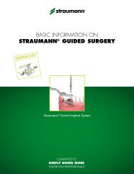
LIT100 - Basic information on the surgical procedure - Straumann
LIT100 - Basic information on the surgical procedure - Straumann
LIT100 - Basic information on the surgical procedure - Straumann

You also want an ePaper? Increase the reach of your titles
YUMPU automatically turns print PDFs into web optimized ePapers that Google loves.
<str<strong>on</strong>g>Basic</str<strong>on</strong>g> <str<strong>on</strong>g>informati<strong>on</strong></str<strong>on</strong>g> <strong>on</strong> <strong>the</strong><br />
<strong>surgical</strong> <strong>procedure</strong><br />
<strong>Straumann</strong> ® Dental Implant System
®<br />
<strong>Straumann</strong> is <strong>the</strong> industrial partner of <strong>the</strong> ITI (Internati<strong>on</strong>al Team for Implantology)<br />
in <strong>the</strong> areas of research, development and educati<strong>on</strong>.
C<strong>on</strong>tents<br />
About this guide 2<br />
1. The <strong>Straumann</strong> ® Dental Implant System 3<br />
1.1 Overview 3<br />
1.2 Implant lines 6<br />
1.2.1 <strong>Straumann</strong> Standard Implant 6<br />
1.2.2 <strong>Straumann</strong> Standard Plus Implant 6<br />
1.2.3 <strong>Straumann</strong> Tapered Effect Implant 6<br />
1.2.4 <strong>Straumann</strong> B<strong>on</strong>e Level Implant 6<br />
1.3 Implant-abutment c<strong>on</strong>necti<strong>on</strong>s 7<br />
1.3.1 <strong>Straumann</strong> synOcta ®<br />
Morse taper c<strong>on</strong>necti<strong>on</strong> 7<br />
1.3.2 <strong>Straumann</strong> Narrow Neck C<strong>on</strong>necti<strong>on</strong> 7<br />
1.3.3 <strong>Straumann</strong> B<strong>on</strong>e Level CrossFit ®<br />
C<strong>on</strong>necti<strong>on</strong> 8<br />
1.4 Surfaces 9<br />
1.4.1 <strong>Straumann</strong> SLActive ® 9<br />
1.4.2 <strong>Straumann</strong> SLA ® 9<br />
1.5 Materials 10<br />
1.5.1 Titanium 10<br />
1.5.2 Roxolid ® 10<br />
2. Indicati<strong>on</strong>s and C<strong>on</strong>traindicati<strong>on</strong>s 11<br />
2.1 Intended use 11<br />
2.1.1 Indicati<strong>on</strong>s for small diameter<br />
(Ø 3.3 mm) implants 11<br />
2.1.2 Indicati<strong>on</strong>s for Titanium grade 4<br />
Standard/Standard Plus implants (Ø 3.3 RN) 11<br />
2.1.3 Specific indicati<strong>on</strong>s for <strong>Straumann</strong> ®<br />
implants with a length of 6.0 mm 11<br />
2.2 C<strong>on</strong>traindicati<strong>on</strong>s 11<br />
2.2.1 Relative c<strong>on</strong>traindicati<strong>on</strong>s 11<br />
2.2.2 Local c<strong>on</strong>traindicati<strong>on</strong>s 11<br />
2.3 Implant specific indicati<strong>on</strong>s 12<br />
2.3.1 Titanium implants 12<br />
2.3.2 Roxolid ® implants 16<br />
3. Preoperative Planning 17<br />
3.1 Implant positi<strong>on</strong> 17<br />
3.1.1 Mesiodistal implant positi<strong>on</strong> 18<br />
3.1.1.1 Examples of single tooth gaps 19<br />
3.1.1.2 Examples of multiple tooth gaps 21<br />
3.1.2 Orofacial implant positi<strong>on</strong> 22<br />
3.1.3 Cor<strong>on</strong>oapical implant positi<strong>on</strong> 23<br />
3.2 Planning aids 25<br />
3.2.1 Mesiodistal and orofacial space<br />
requirements 25<br />
3.2.1.1 Diagnostic T for <strong>Straumann</strong> Standard,<br />
Standard Plus, and Tapered Effect implants 25<br />
3.2.1.2 <strong>Straumann</strong> Implant Distance Indicator 26<br />
3.2.2 Determining vertical b<strong>on</strong>e availability 27<br />
3.2.2.1 X-ray reference sphere 27<br />
3.2.2.2 X-ray templates 28<br />
3.2.3 Surgical drill template 30<br />
3.2.3.1 Vacuum-formed drill template 30<br />
3.2.3.2 Thermoplastic drill template 31<br />
4. Surgical Procedure 32<br />
4.1 Implant bed preparati<strong>on</strong> 32<br />
4.1.1 Initial implant bed preparati<strong>on</strong> 33<br />
4.1.2 Final implant bed preparati<strong>on</strong> 37<br />
4.1.3 Examples for final implant bed preparati<strong>on</strong> 40<br />
4.2 Opening <strong>the</strong> implant package 44<br />
4.3 Placing <strong>the</strong> implant 46<br />
4.4 Soft tissue management 52<br />
4.4.1 Submucosal healing 52<br />
4.4.2 Transmucosal healing 55<br />
5. Healing Phase 65<br />
5.1 Healing phase durati<strong>on</strong> 65<br />
5.2 <strong>Straumann</strong> SLActive and SLA in comparis<strong>on</strong> 65<br />
6. Additi<strong>on</strong>al Informati<strong>on</strong> <strong>on</strong> Instruments 66<br />
6.1 Surgical instruments 66<br />
6.1.1 Depth marks <strong>on</strong> <strong>Straumann</strong> instruments 66<br />
6.1.2 Single-patient pilot and twist drills 67<br />
6.1.3 <strong>Straumann</strong> Drill Stops 67<br />
6.1.4 <strong>Straumann</strong> Surgical cassette 69<br />
6.1.5 Ratchet 71<br />
6.1.6 Holding key 72<br />
6.1.7 SCS screwdrivers 72<br />
6.2 Osteotomes 73<br />
6.2.1 Instrument set for b<strong>on</strong>e c<strong>on</strong>densati<strong>on</strong> 73<br />
6.2.2 Instrument set for transalveolar sinus floor<br />
elevati<strong>on</strong> 73<br />
6.2.3 Depth stops for osteotomes 73<br />
6.3 Cleaning and care of instruments 74<br />
7. Appendix 76<br />
7.1 Labeling and color coding of <strong>the</strong><br />
<strong>Straumann</strong> Dental Implant System 76<br />
7.2 Related documentati<strong>on</strong> 78<br />
7.3 Important notes 80<br />
8. Index 81
about this guide<br />
<str<strong>on</strong>g>Basic</str<strong>on</strong>g> Informati<strong>on</strong> <strong>on</strong> <strong>the</strong> Surgical Procedure for <strong>the</strong> <strong>Straumann</strong> ® Dental Implant<br />
System provides dental practiti<strong>on</strong>ers and related specialists with <strong>the</strong> essential<br />
steps regarding <strong>surgical</strong> treatment, planning, and <strong>procedure</strong>.<br />
The manual is divided into <strong>the</strong> following main parts:<br />
■ The <strong>Straumann</strong> Dental Implant System<br />
■ Indicati<strong>on</strong>s and C<strong>on</strong>traindicati<strong>on</strong>s<br />
■ Preoperative Planning<br />
■ Surgical Procedures<br />
■ Healing Phase<br />
■ Additi<strong>on</strong>al Informati<strong>on</strong> <strong>on</strong> Instruments<br />
■ Appendix<br />
For fur<strong>the</strong>r <str<strong>on</strong>g>informati<strong>on</strong></str<strong>on</strong>g> regarding <strong>the</strong> <strong>Straumann</strong> Dental Implant System, visit our<br />
comprehensive website at www.straumann.com.<br />
2
1. THE STRAUMANN ® DENTAL IMPLANT SYSTEM<br />
1.1 Overview<br />
The <strong>Straumann</strong> Dental Implant System offers four implant<br />
lines with diverse body and neck designs, ranging from<br />
<strong>the</strong> classic soft tissue level to <strong>the</strong> b<strong>on</strong>e level implant. All<br />
implants can be placed with <strong>on</strong>e <strong>surgical</strong> kit while using<br />
very similar <strong>surgical</strong> <strong>procedure</strong>s.<br />
<strong>Straumann</strong> implants have been extensively researched.<br />
Their optimized design, called B<strong>on</strong>e C<strong>on</strong>trol Design ® ,<br />
is based <strong>on</strong> <strong>the</strong> five key biological principles in implant<br />
dentistry: osseoc<strong>on</strong>ductivity, c<strong>on</strong>trol of <strong>the</strong> microgap,<br />
biomechanical implant design, biological distance, and <strong>the</strong><br />
locati<strong>on</strong> of <strong>the</strong> surface margin. With B<strong>on</strong>e C<strong>on</strong>trol Design,<br />
<strong>Straumann</strong> implants are designed to achieve optimal<br />
preservati<strong>on</strong> of crestal b<strong>on</strong>e and soft tissue stability.<br />
S SP TE BL<br />
2.8 mm<br />
1.8 mm<br />
<strong>Straumann</strong><br />
Standard<br />
Implant (S)<br />
<strong>Straumann</strong><br />
Standard Plus<br />
Implant (SP)<br />
<strong>Straumann</strong><br />
Tapered Effect<br />
Implant (TE)<br />
<strong>Straumann</strong><br />
B<strong>on</strong>e Level<br />
Implant (BL)<br />
The classic soft<br />
tissue level implant<br />
The implant for<br />
flexible placement<br />
The implant for<br />
immediate<br />
placement<br />
<strong>Straumann</strong><br />
expertise applied<br />
at b<strong>on</strong>e level<br />
<strong>Straumann</strong> dental implants are available in three endosteal diameters: Ø 3.3 mm, Ø 4.1 mm, and Ø 4.8 mm.<br />
A unified color code simplifies identificati<strong>on</strong> of instruments and implants.<br />
Color coding<br />
yellow<br />
red<br />
green<br />
Endosteal implant diameter 3.3 mm<br />
Endosteal implant diameter 4.1 mm<br />
Endosteal implant diameter 4.8 mm<br />
1. The <strong>Straumann</strong> ® Dental Implant System 1.1 Overview<br />
3
Implant<br />
overview<br />
Neck<br />
diameter<br />
<strong>Straumann</strong> ® Standard Implant<br />
<strong>Straumann</strong> ® Standard Plu<br />
S Ø 3.3 RN S Ø 4.1 RN S Ø 4.8 RN S Ø 4.8 WN SP Ø 3.3 NN SP Ø 3.3 RN SP Ø 4.1 RN<br />
Ø 4.8 mm Ø 4.8 mm Ø 4.8 mm Ø 6.5 mm Ø 3.5 mm Ø 4.8 mm Ø 4.8 mm<br />
Roxolid ®<br />
2.8 mm<br />
Titanium<br />
Endosteal<br />
diameter<br />
SLActive ®<br />
SLActive ®<br />
SLA ®<br />
C<strong>on</strong>necti<strong>on</strong><br />
Ø 3.3 mm Ø 4.1 mm Ø 4.8 mm Ø 4.8 mm Ø 3.3 mm Ø 3.3 mm Ø 4.1 mm<br />
8 mm 033.431S 033.451S<br />
10 mm 033.432S 033.452S<br />
12 mm 033.433S 033.453S<br />
14 mm 033.434S 033.454S<br />
16 mm 033.435S<br />
6 mm 033.030S 033.230S 033.630S 033.050S<br />
8 mm 033.131S 033.031S 033.231S 033.631S 033.951S 033.151S 033.051S<br />
10 mm 033.132S 033.032S 033.232S 033.632S 033.952S 033.152S 033.052S<br />
12 mm 033.133S 033.033S 033.233S 033.633S 033.953S 033.153S 033.053S<br />
14 mm 033.134S 033.034S 033.234S 033.954S 033.154S 033.054S<br />
16 mm 033.135S 033.035S<br />
6 mm 043.030S 043.230S 043.630S 043.050S<br />
8 mm 043.131S 043.031S 043.231S 043.631S 042.930S 043.151S 043.051S<br />
10 mm 043.132S 043.032S 043.232S 043.632S 042.931S 043.152S 043.052S<br />
12 mm 043.133S 043.033S 043.233S 043.633S 042.932S 043.153S 043.053S<br />
14 mm 043.134S 043.034S 043.234S 042.933S 043.154S 043.054S<br />
16 mm 043.135S 043.035S<br />
RN RN RN WN NN RN RN<br />
Pros<strong>the</strong>tic<br />
restorati<strong>on</strong><br />
comp<strong>on</strong>ents<br />
RN synOcta ®<br />
RN Solid Abutment<br />
RN synOcta ®<br />
RN Solid Abutment<br />
Retentive Anchor<br />
steco ®<br />
Titanmagnetics ®<br />
LOCATOR ® RN synOcta ®<br />
RN Solid Abutment<br />
Retentive Anchor<br />
steco ®<br />
Titanmagnetics ®<br />
LOCATOR ® WN synOcta ®<br />
WN Solid Abutment<br />
NN RN synOcta ®<br />
RN Solid Abutment<br />
RN synOcta ®<br />
RN Solid Abutment<br />
Retentive Anchor<br />
steco ®<br />
Titanmagnetics ®<br />
LOCATOR ®<br />
4 1. The <strong>Straumann</strong> ® Dental Implant System 1.1 Overview
s Implant <strong>Straumann</strong> ® Tapered Effect Implant <strong>Straumann</strong> ® B<strong>on</strong>e Level Implant<br />
SP Ø 4.8 RN SP Ø 4.8 WN TE Ø 3.3 RN TE Ø 4.1 RN TE Ø 4.8 WN BL Ø 3.3 NC BL Ø 4.1 RC BL Ø 4.8 RC<br />
Ø 4.8 mm Ø 6.5 mm Ø 4.8 mm Ø 4.8 mm Ø 6.5 mm Ø 3.3 mm Ø 4.1 mm Ø 4.8 mm<br />
1.8 mm<br />
1.8 mm<br />
Ø 4.8 mm Ø 4.8 mm Ø 3.3 mm Ø 4.1 mm Ø 4.8 mm Ø 3.3 mm Ø 4.1 mm Ø 4.8 mm<br />
033.751S 021.2208<br />
033.752S 021.2210<br />
033.753S 021.2212<br />
033.754S 021.2214<br />
033.250S 033.650S<br />
033.251S 033.651S 033.721S 033.761S 021.2108 021.4108 021.6108<br />
033.252S 033.652S 033.722S 033.762S 033.712S 021.2110 021.4110 021.6110<br />
033.253S 033.653S 033.723S 033.763S 033.713S 021.2112 021.4112 021.6112<br />
033.254S 033.724S 033.764S 033.714S 021.2114 021.4114 021.6114<br />
043.250S 043.650S<br />
043.251S 043.651S 043.721S 043.761S 021.2408 021.4408 021.6408<br />
043.252S 043.652S 043.722S 043.762S 043.712S 021.2410 021.4410 021.6410<br />
043.253S 043.653S 043.723S 043.763S 043.713S 021.2412 021.4412 021.6412<br />
043.254S 043.724S 043.764S 043.714S 021.2414 021.4414 021.6414<br />
RN WN RN RN WN NC RC RC<br />
RN synOcta ® WN synOcta ®<br />
RN Solid Abutment WN Solid Abutment<br />
Retentive Anchor<br />
steco ®<br />
Titanmagnetics ®<br />
LOCATOR ®<br />
RN synOcta ®<br />
RN Solid Abutment<br />
Retentive Anchor<br />
steco ®<br />
Titanmagnetics ®<br />
LOCATOR ® RN synOcta ®<br />
RN Solid Abutment<br />
Retentive Anchor<br />
steco ®<br />
Titanmagnetics ®<br />
LOCATOR ® WN synOcta ®<br />
WN Solid Abutment<br />
NC CrossFit ® RC CrossFit ® RC CrossFit ®<br />
steco ® and Titanmagnetics ® are trademarks of steco-system-technik GmbH & Co. KG, Germany<br />
LOCATOR ® is a registered trademark of Zest Anchors, Inc., USA..<br />
1. The <strong>Straumann</strong> ® Dental Implant System 1.1 Overview 5
1.2 Implant lines<br />
1.2.1 <strong>Straumann</strong> ® Standard Implant – The classic soft<br />
tissue level implant<br />
<strong>Straumann</strong> Standard implants have a smooth neck secti<strong>on</strong><br />
of 2.8 mm and are especially suitable for single-stage<br />
<strong>procedure</strong>s, where <strong>the</strong> implant is placed at <strong>the</strong> soft<br />
tissue level and not covered with soft tissue during <strong>the</strong><br />
healing phase. The standard implant uses <strong>the</strong> <strong>Straumann</strong><br />
synOcta ® c<strong>on</strong>necti<strong>on</strong> toge<strong>the</strong>r with its corresp<strong>on</strong>ding<br />
pros<strong>the</strong>tic comp<strong>on</strong>ents: synOcta portfolio and <strong>the</strong><br />
<strong>Straumann</strong> Solid Abutment. The thread pitch <strong>on</strong> standard<br />
implants measures 1.0 mm for <strong>the</strong> Ø 3.3 mm implants,<br />
and 1.25 mm for all o<strong>the</strong>r diameters.<br />
1.2.3 <strong>Straumann</strong> Tapered Effect Implant –<br />
The implant for immediate placement<br />
<strong>Straumann</strong> Tapered Effect implants have a special<br />
anatomical design, which combines a cylindrical shape<br />
in its apical regi<strong>on</strong> and a c<strong>on</strong>ical shape in <strong>the</strong> cor<strong>on</strong>al<br />
regi<strong>on</strong>, making this implant particularly suitable for<br />
immediate or early implantati<strong>on</strong> following extracti<strong>on</strong> or<br />
loss of natural teeth. With <strong>the</strong> smooth neck secti<strong>on</strong> of<br />
1.8 mm, healing can occur trans- or subgingivally.<br />
Tapered effect implants have a synOcta c<strong>on</strong>necti<strong>on</strong>;<br />
<strong>the</strong> pros<strong>the</strong>tic comp<strong>on</strong>ents of <strong>the</strong> synOcta portfolio and<br />
<strong>the</strong> <strong>Straumann</strong> Solid Abutment can be used. The thread<br />
pitch of 0.8 mm provides excellent primary stability.<br />
1.2.2 <strong>Straumann</strong> Standard Plus Implant –<br />
The implant for flexible placement<br />
<strong>Straumann</strong> Standard Plus implants c<strong>on</strong>sist of a smooth<br />
neck secti<strong>on</strong> of 1.8 mm that allows flexible cor<strong>on</strong>oapical<br />
implant placement in combinati<strong>on</strong> with trans- or subgingival<br />
healing. Standard plus implants offer <strong>the</strong> dental<br />
surge<strong>on</strong> additi<strong>on</strong>al treatment opti<strong>on</strong>s that are particularly<br />
useful in <strong>the</strong> anterior regi<strong>on</strong> of <strong>the</strong> maxilla, where es<strong>the</strong>tic<br />
demands are high. Similar to <strong>Straumann</strong> Standard<br />
implants, this implant type uses <strong>the</strong> <strong>Straumann</strong> synOcta<br />
c<strong>on</strong>necti<strong>on</strong> toge<strong>the</strong>r with its corresp<strong>on</strong>ding pros<strong>the</strong>tic<br />
comp<strong>on</strong>ents: synOcta portfolio and <strong>the</strong> <strong>Straumann</strong> Solid<br />
Abutment. The thread pitch <strong>on</strong> <strong>the</strong> standard plus implant<br />
measures 1.0 mm for <strong>the</strong> Ø 3.3 mm implants, and 1.25<br />
mm for all o<strong>the</strong>r diameters.<br />
1.2.4 <strong>Straumann</strong> B<strong>on</strong>e Level Implant –<br />
<strong>Straumann</strong> expertise applied at b<strong>on</strong>e level<br />
<strong>Straumann</strong> B<strong>on</strong>e Level implants are suitable for b<strong>on</strong>e<br />
level treatments in combinati<strong>on</strong> with trans- or subgingival<br />
healing. The implant’s rough surface extends to <strong>the</strong> top<br />
of <strong>the</strong> implant and <strong>the</strong> c<strong>on</strong>necti<strong>on</strong> is shifted inwards. The<br />
B<strong>on</strong>e Level implant uses a c<strong>on</strong>ical-cylindrical c<strong>on</strong>necti<strong>on</strong>,<br />
<strong>the</strong> CrossFit ® C<strong>on</strong>necti<strong>on</strong>, toge<strong>the</strong>r with corresp<strong>on</strong>ding<br />
pros<strong>the</strong>tic CrossFit comp<strong>on</strong>ents from <strong>the</strong> B<strong>on</strong>e Level<br />
product portfolio to provide c<strong>on</strong>sistent emergence profiles<br />
and es<strong>the</strong>tic results. A cylindrical outer c<strong>on</strong>tour and a<br />
thread pitch of 0.8 mm that tapers off in <strong>the</strong> cor<strong>on</strong>al part<br />
of <strong>the</strong> implant, provides excellent primary stability.<br />
<strong>Straumann</strong> Standard Plus Narrow Neck implants can<br />
be used as an alternative soluti<strong>on</strong> for narrow anterior<br />
interdental spaces. They are very flexible for indicati<strong>on</strong>s<br />
where es<strong>the</strong>tic demands are high. This <strong>on</strong>e-piece design<br />
implant has an external c<strong>on</strong>necti<strong>on</strong> with a shoulder<br />
diameter of 3.5 mm, an endosteal diameter of 3.3 mm,<br />
and a smooth neck secti<strong>on</strong> of 1.8 mm. Narrow neck<br />
implants use <strong>the</strong>ir proprietary narrow neck (NN) pros<strong>the</strong>tic<br />
comp<strong>on</strong>ents. The implant has a thread pitch of 1.0 mm.<br />
6 1. The <strong>Straumann</strong> ® Dental Implant System 1.2 Implant lines
1.3 Implant-abutment c<strong>on</strong>necti<strong>on</strong>s<br />
1.3.1 <strong>Straumann</strong> ® synOcta ® Morse taper c<strong>on</strong>necti<strong>on</strong><br />
The mechanically locking fricti<strong>on</strong> fit of <strong>the</strong> <strong>Straumann</strong><br />
synOcta internal c<strong>on</strong>necti<strong>on</strong>, with its 8˚ Morse taper<br />
c<strong>on</strong>necti<strong>on</strong>, is designed to provide a more secure implant<br />
to abutment c<strong>on</strong>necti<strong>on</strong>.<br />
The <strong>Straumann</strong> synOcta c<strong>on</strong>necti<strong>on</strong> is available for all<br />
<strong>Straumann</strong> Standard, Standard Plus, and Tapered Effect<br />
implants with <strong>the</strong> Regular Neck (RN) and Wide Neck<br />
(WN) platform.<br />
1.3.2 <strong>Straumann</strong> Narrow Neck c<strong>on</strong>necti<strong>on</strong><br />
The <strong>on</strong>e-part <strong>Straumann</strong> Standard Plus Narrow Neck implant<br />
has a built-in octa abutment (1.5 mm in height) that provides<br />
a solid base for narrow pros<strong>the</strong>tic abutment copings.<br />
The Narrow Neck c<strong>on</strong>necti<strong>on</strong> is available for <strong>Straumann</strong><br />
Standard Plus Narrow Neck implants <strong>on</strong>ly.<br />
1. The <strong>Straumann</strong> ® Dental Implant System 1.3 Implant-abutment c<strong>on</strong>necti<strong>on</strong>s<br />
7
1.3.3 <strong>Straumann</strong> ® B<strong>on</strong>e Level CrossFit ® C<strong>on</strong>necti<strong>on</strong><br />
The CrossFit C<strong>on</strong>necti<strong>on</strong> of <strong>Straumann</strong> B<strong>on</strong>e Level implants features a<br />
mechanically locking fricti<strong>on</strong> fit that is designed to drastically reduce screw<br />
loosening. The CrossFit C<strong>on</strong>necti<strong>on</strong> is available for <strong>Straumann</strong> B<strong>on</strong>e Level<br />
implants <strong>on</strong>ly.<br />
NC<br />
RC<br />
<strong>Straumann</strong> B<strong>on</strong>e Level Ø 4.1 mm and Ø 4.8 mm implants<br />
have <strong>the</strong> same c<strong>on</strong>necti<strong>on</strong>, <strong>the</strong> regular CrossFit<br />
C<strong>on</strong>necti<strong>on</strong> (RC), and share <strong>the</strong> same healing,<br />
temporizati<strong>on</strong>, and final pros<strong>the</strong>tic comp<strong>on</strong>ents.<br />
<strong>Straumann</strong> B<strong>on</strong>e Level Ø 3.3 mm implants feature <strong>the</strong><br />
narrow CrossFit C<strong>on</strong>necti<strong>on</strong> (NC).<br />
The corresp<strong>on</strong>ding sec<strong>on</strong>dary comp<strong>on</strong>ents are color-coded:<br />
• yellow = NC c<strong>on</strong>necti<strong>on</strong><br />
• magenta = RC c<strong>on</strong>necti<strong>on</strong><br />
Ø 3.3 mm Ø 4.1 mm Ø 4.8 mm<br />
8 1. The <strong>Straumann</strong> ® Dental Implant System 1.3 Implant-abutment c<strong>on</strong>necti<strong>on</strong>s
1.4 Surfaces<br />
<strong>Straumann</strong> ® implants are manufactured from biocompatible pure Grade 4 titanium. Standard, Standard Plus, Tapered<br />
Effect and B<strong>on</strong>e Level implants are available with <strong>the</strong> SLActive ® or <strong>the</strong> SLA ® surfaces.<br />
1.4.1 <strong>Straumann</strong> SLActive surface<br />
The SLActive surface features <strong>the</strong> scientifically proven SLA<br />
surface topography. Additi<strong>on</strong>ally, it exhibits <strong>the</strong> surface<br />
properties of hydrophilicity and chemical activity, which<br />
can significantly accelerate <strong>the</strong> entire osseointegrati<strong>on</strong><br />
process, under <strong>the</strong> appropriate clinical circumstances.<br />
Hydrophilicity<br />
The hydrophilic properties of SLActive enable a larger<br />
accessible surface area for increased blood c<strong>on</strong>tact and<br />
b<strong>on</strong>e cell attachment.<br />
Chemical activity<br />
The chemical activity of SLActive provides ideal<br />
c<strong>on</strong>diti<strong>on</strong>s for direct protein adsorpti<strong>on</strong>, promoting faster<br />
osseointegrati<strong>on</strong> in comparis<strong>on</strong> to SLA.*<br />
<strong>Straumann</strong><br />
SLActive –<br />
surface innovati<strong>on</strong><br />
■ Proven SLA<br />
surface<br />
topography<br />
■ Hydrophilicity<br />
for a larger<br />
accessible<br />
surface area<br />
■ Chemical activity<br />
promoting faster<br />
osseointegrati<strong>on</strong><br />
1.4.2 <strong>Straumann</strong> SLA<br />
The SLA surface is produced using a large-grit sandblasting technique that<br />
generates a macro-roughness <strong>on</strong> <strong>the</strong> titanium surface. Following, an<br />
acid-etching technique superimposes a micro-roughness <strong>on</strong> <strong>the</strong> titanium<br />
surface. The resulting topography offers <strong>the</strong> ideal structure for cell attachment<br />
and is <strong>the</strong> basis for <strong>the</strong> fur<strong>the</strong>r developed SLActive surface.<br />
*As shown in animal model.<br />
1. The <strong>Straumann</strong> ® Dental Implant System 1.4 Surfaces<br />
9
1.5 Materials<br />
<strong>Straumann</strong> provides implants made of pure titanium grade 4 and a titanium zirc<strong>on</strong>ium alloy (Roxolid ® ).<br />
1.5.1 Titanium<br />
The complete <strong>Straumann</strong> ® implant porfolio is available made of titanium grade 4. <strong>Straumann</strong> titanium grade<br />
4 is cold worked in order to enhance <strong>the</strong> mechanical strength. Titanium has shown excellent l<strong>on</strong>g-term<br />
biocompatability. Its metallic structure allows for producing <strong>the</strong> implants with <strong>the</strong> SLA ® /SLActive ® surface, thus<br />
enabling a good osseointegrati<strong>on</strong>.<br />
1.5.2 Roxolid ®<br />
In additi<strong>on</strong> to titanium implants. <strong>Straumann</strong> ® offers Ø 3.3 mm implants made of a new alloy composed of<br />
titanium and zirc<strong>on</strong>ium, called Roxolid. Roxolid was designed to meet <strong>the</strong> needs of dental surge<strong>on</strong>s. Roxolid<br />
and SLActive ® combine higher tensile 1 and fatigue 2 strength with excellent osseointegrati<strong>on</strong>.<br />
1. In accordance with ASTM F67, data <strong>on</strong> file.<br />
2. <strong>Straumann</strong> data <strong>on</strong> file.<br />
10 1. The <strong>Straumann</strong> ® Dental Implant System 1.5 Materials
2. INDICATIONS AND CONTRAINDICATIONS<br />
2.1 Intended Use<br />
<strong>Straumann</strong> ® dental implants are suitable for <strong>the</strong> treatment<br />
or oral endosteal implantati<strong>on</strong> in <strong>the</strong> upper and lower<br />
jaw and for <strong>the</strong> functi<strong>on</strong>al and es<strong>the</strong>tic oral rehabiliti<strong>on</strong><br />
of edentulous and partialy dentate patients (unless<br />
specific indicati<strong>on</strong>s and limitati<strong>on</strong>s are present, as stated<br />
below). <strong>Straumann</strong> dental implants can also be used<br />
for immediate or early implantati<strong>on</strong> following extracti<strong>on</strong><br />
of loss of natural teeth. <strong>Straumann</strong> implants are cleared<br />
within <strong>the</strong> scope of indicati<strong>on</strong>s, for immediate restorati<strong>on</strong><br />
in single tooth gaps and in an edentulous or partially<br />
dentate jaw; good primary stability and an appropriate<br />
occlusal load are essental. Two or more adjacent<br />
implants should be pros<strong>the</strong>tically c<strong>on</strong>nected toge<strong>the</strong>r<br />
if restored immediately. In <strong>the</strong> case of immediately<br />
restored edentulous situati<strong>on</strong>s, at least 4 implants must<br />
be c<strong>on</strong>nected toge<strong>the</strong>r. Healing phase durati<strong>on</strong> for<br />
delayed restorati<strong>on</strong>s is given <strong>on</strong> page 65. The pros<strong>the</strong>tic<br />
restorati<strong>on</strong>s used are single crowns, bridges and partial<br />
of full dentures, which are c<strong>on</strong>nected to <strong>the</strong> implants by<br />
<strong>the</strong> corresp<strong>on</strong>ding elements (abutments). On pages 12–16<br />
you will find implant specific details about indicati<strong>on</strong>s,<br />
<strong>the</strong> necessary b<strong>on</strong>e volume and <strong>the</strong> spacing between<br />
implants and <strong>the</strong> distance from adjacent teeth.<br />
2.1.1 Indicati<strong>on</strong>s for small diameter<br />
(Ø 3.3 mm) implants<br />
As a general rule, always use <strong>the</strong> largest possible implant<br />
diameter. Because of <strong>the</strong>ir reduced mechanical stability,<br />
small diameter implants are <strong>on</strong>ly used in cases with a low<br />
mechanical load. Placement in <strong>the</strong> molar regi<strong>on</strong> is not<br />
recommended. For fur<strong>the</strong>r restricti<strong>on</strong>s see pages 12, 14,<br />
15 and 16.<br />
2.1.2 Titanium grade 4 Standard/Standard Plus<br />
Implants (Ø 3.3 RN) are to be used <strong>on</strong>ly in cases for<br />
<strong>the</strong> following indicati<strong>on</strong>s<br />
■ Edentulous jaw: 4 implants with a bar for primary<br />
c<strong>on</strong>necti<strong>on</strong><br />
■ Partially dentate jaw in <strong>the</strong> case of implant-borne fixed<br />
restorati<strong>on</strong>s that are combined with Ø 4.1 mm<br />
implants and whose superstructure has primary<br />
splinting.<br />
2.1.3 Specific indicati<strong>on</strong>s for <strong>Straumann</strong> implants with<br />
a length of 6.0 mm<br />
Because of <strong>the</strong> reduced surface area for anchorage in<br />
<strong>the</strong> b<strong>on</strong>e, <strong>the</strong>se implants are to be used solely for <strong>the</strong><br />
following indicati<strong>on</strong>s:<br />
■ As an additi<strong>on</strong>al implant toge<strong>the</strong>r with l<strong>on</strong>ger implants<br />
to support implant-borne rec<strong>on</strong>structi<strong>on</strong>s<br />
■ As an auxiliary implant for implant-borne bar c<strong>on</strong>structi<strong>on</strong>s<br />
supporting full dentures in a seriously atrophied mandible<br />
2.2 C<strong>on</strong>traindicati<strong>on</strong>s<br />
Serious internal medical problems, b<strong>on</strong>e metabolism<br />
disturbances, unc<strong>on</strong>trolled bleeding disorders, inadequate<br />
wound healing capacity, poor oral hygiene, maxillary<br />
and mandibular growth not completed, poor general state<br />
of health, uncooperative or unmotivated patient, drug or<br />
alcohol abuse, psychoses, prol<strong>on</strong>ged <strong>the</strong>rapy-resistant<br />
functi<strong>on</strong>al disorders, xerostomia, weakened immune<br />
system, illnesses requiring periodic use of steroids, titanium<br />
allergy, unc<strong>on</strong>trollable endocrine disorders.<br />
2.2.1 Relative c<strong>on</strong>traindicati<strong>on</strong>s<br />
Previously irradiated b<strong>on</strong>e, diabetes mellitus,<br />
anticoagulati<strong>on</strong> drugs/hemorrhagic dia<strong>the</strong>ses, bruxism,<br />
parafuncti<strong>on</strong>al habits, unfavorable anatomic b<strong>on</strong>e<br />
c<strong>on</strong>diti<strong>on</strong>s, tobacco abuse, unc<strong>on</strong>trolled period<strong>on</strong>titis,<br />
temporomandibular joint disorders, treatable pathologic<br />
diseases of <strong>the</strong> jaw and changes in <strong>the</strong> oral mucosa,<br />
pregnancy, inadequate oral hygiene.<br />
2.2.2 Local c<strong>on</strong>traindicati<strong>on</strong>s<br />
Inadequate b<strong>on</strong>e volume and/or quality, local root<br />
remnants. Attenti<strong>on</strong> should be paid to <strong>the</strong> specific<br />
indicati<strong>on</strong>s of <strong>the</strong> small diameter implants and <strong>the</strong> implants<br />
with a length of 6.0 mm as specified above.<br />
2. Indicati<strong>on</strong>s and C<strong>on</strong>traindicati<strong>on</strong>s 2.1 Intended use | 2.2 C<strong>on</strong>traindicati<strong>on</strong>s<br />
11
2.3 Implant specific indicati<strong>on</strong>s<br />
2.3.1 Titanium implants<br />
Specific indicati<strong>on</strong>s for <strong>Straumann</strong> ® Standard and Standard Plus implants<br />
Implant type<br />
Indicati<strong>on</strong>s and distinctive features<br />
Minimal<br />
ridge<br />
width*<br />
Minimal<br />
site<br />
width**<br />
SP Ø 3.3 mm NN<br />
■ Small diameter implant for narrow interdental spaces and ridges<br />
5.5 mm 5.5 mm<br />
Cauti<strong>on</strong><br />
Placement in <strong>the</strong> molar regi<strong>on</strong> is not recommended<br />
S Ø 3.3 mm RN<br />
SP Ø 3.3 mm RN<br />
■ Alternative in <strong>the</strong> case of a restricted ridge width<br />
■ In view of <strong>the</strong>ir lower mechanical strength compared to <strong>the</strong><br />
Ø 4.1 mm implants, <strong>the</strong>se implants should be used exclusively<br />
for <strong>the</strong> following indicati<strong>on</strong>s:<br />
■ Edentulous jaw:<br />
4 implants S/SP Ø 3.3 RN in c<strong>on</strong>juncti<strong>on</strong> with a bar<br />
c<strong>on</strong>structi<strong>on</strong><br />
■ Partially edentulous jaw:<br />
In <strong>the</strong> case of fixed rec<strong>on</strong>structi<strong>on</strong>, combined with Ø 4.1 mm<br />
implants and splinted with a superstructure<br />
Cauti<strong>on</strong><br />
Placement in <strong>the</strong> molar regi<strong>on</strong> is not recommended<br />
5.5 mm 7.0 mm<br />
S Ø 4.1 mm RN<br />
■ For oral endosteal implant indicati<strong>on</strong>s in <strong>the</strong> maxilla and<br />
mandible, for functi<strong>on</strong>al and es<strong>the</strong>tic rehabilitati<strong>on</strong> of edentulous<br />
and partially edentulous patients<br />
6.0 mm 7.0 mm<br />
SP Ø 4.1 mm RN<br />
S = Standard Implant, SP = Standard Plus Implant<br />
NN = Narrow Neck Ø 3.5 mm, RN = Regular Neck Ø 4.8 mm<br />
c<strong>on</strong>t.<br />
* Minimal ridge width: Minimal orofacial ridge width, rounded off to 0.5 mm<br />
** Minimal site width: Minimal mesial-distal site width for a single tooth restorati<strong>on</strong>, between adjacent teeth, rounded off to 0.5 mm<br />
12 2. Indicati<strong>on</strong>s and C<strong>on</strong>traindicati<strong>on</strong>s 2.3 Implant specific indicati<strong>on</strong>s
Specific indicati<strong>on</strong>s for <strong>Straumann</strong> ® Standard and Standard Plus implants, c<strong>on</strong>t.<br />
Implant type<br />
Indicati<strong>on</strong>s and distinctive features<br />
Minimal<br />
ridge<br />
width*<br />
Minimal<br />
site<br />
width**<br />
S Ø 4.8 mm RN<br />
SP Ø 4.8 mm RN<br />
■ For oral endosteal implant indicati<strong>on</strong>s in <strong>the</strong> maxilla and<br />
mandible, for functi<strong>on</strong>al and es<strong>the</strong>tic rehabilitati<strong>on</strong> of edentulous<br />
and partially edentulous patients<br />
■ The S/SP Ø 4.8 mm implants are especially suited for wider<br />
interdental spaces and ridges<br />
7.0 mm 7.0 mm<br />
S Ø 4.8 mm WN<br />
SP Ø 4.8 mm WN<br />
■ For oral endosteal implant indicati<strong>on</strong>s in <strong>the</strong> maxilla and<br />
mandible, for functi<strong>on</strong>al and es<strong>the</strong>tic rehabilitati<strong>on</strong> of edentulous<br />
and partially edentulous patients<br />
■ The S/SP Ø 4.8 mm implants are especially suited for wider<br />
interdental spaces and ridges<br />
■ S/SP implants with a WN platform are designed for <strong>the</strong>ir<br />
rec<strong>on</strong>structi<strong>on</strong> of teeth with a wider neck diameter<br />
7.0 mm 8.5 mm<br />
S = Standard Implant, SP = Standard Plus Implant<br />
RN = Regular Neck Ø 4.8 mm, WN = Wide Neck Ø 6.5 mm<br />
* Minimal ridge width: Minimal orofacial ridge width, rounded off to 0.5 mm<br />
** Minimal site width: Minimal mesial-distal site width for a single tooth restorati<strong>on</strong>, between adjacent teeth, rounded off to 0.5 mm<br />
2. Indicati<strong>on</strong>s and C<strong>on</strong>traindicati<strong>on</strong>s 2.3 Implant specific indicati<strong>on</strong>s<br />
13
Specific indicati<strong>on</strong>s for <strong>Straumann</strong> ® Tapered Effect implants<br />
Implant type<br />
Indicati<strong>on</strong>s and distinctive features<br />
Minimal<br />
ridge<br />
width*<br />
Minimal<br />
site<br />
width**<br />
TE Ø 3.3 mm RN<br />
■ For oral endosteal implant indicati<strong>on</strong>s in <strong>the</strong> maxilla and<br />
mandible, for functi<strong>on</strong>al and es<strong>the</strong>tic rehabilitati<strong>on</strong> of edentulous<br />
and partially edentulous patients<br />
■ Alternative in dental gaps where <strong>the</strong> roots of adjacent teeth are<br />
close toge<strong>the</strong>r, where implants with a greater endosteal diameter<br />
are c<strong>on</strong>traindicated<br />
Cauti<strong>on</strong><br />
Placement in <strong>the</strong> molar regi<strong>on</strong> is not recommended<br />
7.0 mm 7.0 mm<br />
TE Ø 4.1 mm RN<br />
■ For oral endosteal implant indicati<strong>on</strong>s in <strong>the</strong> maxilla and<br />
mandible, for functi<strong>on</strong>al and es<strong>the</strong>tic rehabilitati<strong>on</strong> of edentulous<br />
and partially edentulous patients<br />
7.0 mm 7.0 mm<br />
TE Ø 4.8 mm WN<br />
■ For oral endosteal implant indicati<strong>on</strong>s in <strong>the</strong> maxilla and<br />
mandible, for functi<strong>on</strong>al and es<strong>the</strong>tic rehabilitati<strong>on</strong> of edentulous<br />
and partially edentulous patients<br />
■ The TE Ø 4.8 mm implants are especially suited for wider<br />
interdental spaces and ridges<br />
8.5 mm 8.5 mm<br />
TE = Tapered Effect Implant<br />
RN = Regular Neck Ø 4.8 mm, WN = Wide Neck Ø 6.5 mm<br />
* Minimal ridge width: Minimal orofacial ridge width between adjacent teeth, rounded off to 0.5 mm<br />
** Minimal site width: Minimal mesial-distal site width for a single tooth restorati<strong>on</strong>, between adjacent teeth,<br />
rounded off to 0.5 mm<br />
14 2. Indicati<strong>on</strong>s and C<strong>on</strong>traindicati<strong>on</strong>s 2.3 Implant specific indicati<strong>on</strong>s
Specific indicati<strong>on</strong>s for <strong>Straumann</strong> ® B<strong>on</strong>e Level implants<br />
Implant type<br />
Indicati<strong>on</strong>s and distinctive features<br />
Minimal<br />
ridge<br />
width*<br />
Minimal<br />
site<br />
width**<br />
BL Ø 3.3 mm NC<br />
■ Small diameter implant for narrow interdental spaces and<br />
ridges<br />
5.5. mm 5.5 mm<br />
Cauti<strong>on</strong><br />
Placement in <strong>the</strong> molar regi<strong>on</strong> is not recommended<br />
BL Ø 4.1 mm RC<br />
■ For oral endosteal implant indicati<strong>on</strong>s in <strong>the</strong> maxilla and<br />
mandible, for functi<strong>on</strong>al and es<strong>the</strong>tic rehabilitati<strong>on</strong> of<br />
edentulous and partially edentulous patients<br />
6.0 mm 6.0 mm<br />
BL Ø 4.8 mm RC<br />
■ For oral endosteal implant indicati<strong>on</strong>s in <strong>the</strong> maxilla and<br />
mandible, for functi<strong>on</strong>al and es<strong>the</strong>tic rehabilitati<strong>on</strong> of<br />
edentulous and partially edentulous patients<br />
■ The BL Ø 4.8 mm implants are especially suited for wider<br />
interdental spaces and ridges<br />
7.0 mm 7.0 mm<br />
BL = B<strong>on</strong>e Level<br />
NC = Narrow CrossFit ® , RC = Regular CrossFit ®<br />
* Minimal ridge width: Minimal orofacial ridge width, rounded off to 0.5 mm<br />
** Minimal site width: Minimal mesial-distal site width for a single tooth restorati<strong>on</strong>, between adjacent teeth, rounded off to 0.5 mm<br />
2. Indicati<strong>on</strong>s and C<strong>on</strong>traindicati<strong>on</strong>s 2.3 Implant specific indicati<strong>on</strong>s<br />
15
Specific indicati<strong>on</strong>s for <strong>Straumann</strong> ® Roxolid ® implants<br />
Implant type<br />
Indicati<strong>on</strong>s and distinctive features<br />
Minimal<br />
ridge<br />
width*<br />
Minimal<br />
gap<br />
width**<br />
S Ø 3.3 mm RN<br />
SLActive ®<br />
Roxolid<br />
■ Ideal in <strong>the</strong> case of a restricted ridge width 5.5 mm 7.0 mm<br />
SP Ø 3.3 mm RN<br />
SLActive<br />
Roxolid<br />
Cauti<strong>on</strong><br />
Placement in <strong>the</strong> molar regi<strong>on</strong> is not recommended<br />
for Ø 3.3 mm implants<br />
TE Ø 3.3 mm RN<br />
SLActive<br />
Roxolid<br />
■ For oral endosteal implant indicati<strong>on</strong>s in <strong>the</strong> maxilla and mandible,<br />
for functi<strong>on</strong>al and es<strong>the</strong>tic rehabilitati<strong>on</strong> of edentulous and partially<br />
edentulous patients<br />
■ Alternative in dental gaps where <strong>the</strong> roots of adjacent teeth are<br />
close toge<strong>the</strong>r, where implants with a greater endosteal diameter<br />
are c<strong>on</strong>traindicated<br />
Cauti<strong>on</strong><br />
Placement in <strong>the</strong> molar regi<strong>on</strong> is not recommended<br />
for Ø 3.3 mm implants<br />
7.0 mm 7.0 mm<br />
BL Ø 3.3 mm NC<br />
SLActive<br />
Roxolid<br />
■ Small diameter implant for narrow interdental spaces and ridges<br />
Cauti<strong>on</strong><br />
Placement in <strong>the</strong> molar regi<strong>on</strong> is not recommended<br />
for Ø 3.3 mm implants<br />
5.5 mm 5.5 mm<br />
S = Standard SP = Standard Plus TE = Tapered Effect, BL = B<strong>on</strong>e Level<br />
RN = Regular Neck Ø 4,8 mm NC = Narrow CrossFit ®<br />
* Minimal ridge width: Minimal orofacial ridge width between adjacent teeth, rounded off to 0,5 mm<br />
** Minimal gap width: Minimal mesial-distal gap width for a single tooth restorati<strong>on</strong>, between adjacent teeth, rounded off to 0,5 mm<br />
16 2. Indicati<strong>on</strong>s and C<strong>on</strong>traindicati<strong>on</strong>s 2.3 Implant specific indicati<strong>on</strong>s
3. PREOPERATIVE PLANNING<br />
3.1 Implant positi<strong>on</strong><br />
The implant is <strong>the</strong> focal point of <strong>the</strong> restorati<strong>on</strong>, and provides<br />
<strong>the</strong> basis for planning <strong>the</strong> <strong>surgical</strong> <strong>procedure</strong>. Close<br />
communicati<strong>on</strong> between <strong>the</strong> patient, dentist, surge<strong>on</strong> and<br />
dental technician is imperative for achieving <strong>the</strong> desired<br />
pros<strong>the</strong>tic result.<br />
To establish <strong>the</strong> topographical situati<strong>on</strong>, <strong>the</strong> axial orientati<strong>on</strong><br />
and <strong>the</strong> choice of implants, we recommend <strong>the</strong> following:<br />
■ Make a wax-up/set-up <strong>on</strong> <strong>the</strong> previously prepared<br />
study cast.<br />
■ Define <strong>the</strong> type of superstructure.<br />
The wax-up/set-up can later be used as <strong>the</strong> basis for a<br />
custom-made X-ray or drill template, and for a temporary<br />
restorati<strong>on</strong>.<br />
The implant diameter, implant type, positi<strong>on</strong> and number of<br />
implants should be selected individually, taking <strong>the</strong> anatomy<br />
and spatial circumstances (e.g., malpositi<strong>on</strong>ed or inclined<br />
teeth) into account. The measurements given here should be<br />
regarded as minimum guidelines. Only when <strong>the</strong> minimum distances<br />
are observed is it possible to design <strong>the</strong> restorati<strong>on</strong> so<br />
that <strong>the</strong> necessary oral hygiene measures can be carried out.<br />
The final hard and soft tissue resp<strong>on</strong>se is influenced by <strong>the</strong><br />
positi<strong>on</strong> between <strong>the</strong> implant and <strong>the</strong> proposed restorati<strong>on</strong>.<br />
Therefore, it should be based <strong>on</strong> <strong>the</strong> positi<strong>on</strong> of <strong>the</strong> implantabutment<br />
c<strong>on</strong>necti<strong>on</strong>. The implant positi<strong>on</strong> can be viewed<br />
in three dimensi<strong>on</strong>s:<br />
■ Mesiodistal<br />
■ Orofacial<br />
■ Cor<strong>on</strong>oapical<br />
Note<br />
The implant abutments should always be loaded axially.<br />
Ideally, <strong>the</strong> l<strong>on</strong>g axis of <strong>the</strong> implant is aligned with <strong>the</strong><br />
cusps of <strong>the</strong> opposing tooth. Extreme cusp formati<strong>on</strong> should<br />
be avoided. As it can lead to unphysiological loading.<br />
3. Preoperative Planning 3.1 Implant positi<strong>on</strong><br />
17
3.1.1 Mesiodistal implant positi<strong>on</strong><br />
The mesiodistal b<strong>on</strong>e availability is an important factor for choosing <strong>the</strong> implant type and diameter, as well as <strong>the</strong><br />
interimplant distances in <strong>the</strong> case of multiple implants. The point of reference <strong>on</strong> <strong>the</strong> implant for measuring mesiodistal<br />
distances is always <strong>the</strong> shoulder, as it is <strong>the</strong> widest part of <strong>the</strong> implant. Note that all distances given in this chapter are<br />
rounded off to 0.5 mm. The following basic rules must be applied:<br />
Rule 1<br />
Distance to adjacent tooth at b<strong>on</strong>e level:<br />
A minimal distance of 1.5 mm from <strong>the</strong> implant shoulder to <strong>the</strong> adjacent tooth at b<strong>on</strong>e level (mesial and distal)<br />
is required.<br />
S/SP implants TE implants BL implants<br />
≥1.5 mm<br />
≥1.5 mm<br />
≥1.5 mm<br />
Rule 2<br />
Distance to adjacent implants at b<strong>on</strong>e level:<br />
A minimal distance of 3.0 mm between two adjacent implant shoulders (mesiodistal) is required.<br />
S/SP implants TE implants BL implants<br />
≥3.0 mm<br />
≥3.0 mm<br />
≥3.0 mm<br />
18 3. Preoperative Planning 3.1 Implant positi<strong>on</strong>
3.1.1.1 Examples of single tooth gaps<br />
For single tooth restorati<strong>on</strong>s, <strong>the</strong> implant is centered within <strong>the</strong> single tooth site.<br />
The following examples show how rule 1 is implemented.<br />
<strong>Straumann</strong> ® Standard, Standard Plus, and Tapered Effect implants<br />
For soft tissue level implants, <strong>the</strong> width of <strong>the</strong> site has to be c<strong>on</strong>sidered for <strong>the</strong><br />
selecti<strong>on</strong> of <strong>the</strong> shoulder diameter (NN, RN, WN). In order to make use of <strong>the</strong><br />
site width in c<strong>on</strong>juncti<strong>on</strong> with rule 1, <strong>the</strong> following approximati<strong>on</strong> can be used.<br />
Distance between adjacent<br />
teeth at b<strong>on</strong>e level<br />
0.5 mm Site width 0.5 mm<br />
The distance between adjacent teeth at b<strong>on</strong>e level is approximately 1.0 mm<br />
(2 x 0.5 mm) more than <strong>the</strong> site width. Hence, applying rule 1, <strong>the</strong> site width<br />
must be 2.0 mm wider than <strong>the</strong> implant shoulder.<br />
3. Preoperative Planning 3.1 Implant positi<strong>on</strong><br />
19
S/SP/TE implants<br />
Shoulder diameter<br />
D (mm)<br />
Site width<br />
a min<br />
(mm)<br />
Distance between adjacent<br />
teeth at b<strong>on</strong>e level<br />
b min<br />
(mm)<br />
b<br />
Ø 3.5 (NN) 5.5 6.5<br />
a<br />
D<br />
Ø 4.8 (RN) 7.0 8.0<br />
Ø 6.5 (WN) 8.5 9.5<br />
Rule D + 2.0 mm D + 3.0 mm*<br />
≥1.5 mm ≥1.5 mm<br />
*Rule 1 applied <strong>on</strong> both implant sides<br />
The Diagnostic T (see page 25), applied in <strong>the</strong> patient’s mouth or <strong>on</strong> <strong>the</strong> cast, can be used to obtain an initial measurement of <strong>the</strong> site width for <strong>the</strong><br />
choice of <strong>the</strong> implant shoulder diameter and pros<strong>the</strong>tic rec<strong>on</strong>structi<strong>on</strong>.<br />
Single tooth gaps<br />
For <strong>Straumann</strong> ® B<strong>on</strong>e Level implants, <strong>the</strong> distance between adjacent teeth at b<strong>on</strong>e level determines <strong>the</strong> implant<br />
diameter.<br />
BL implants<br />
Implant diameter<br />
D (mm)<br />
Site width<br />
a min<br />
(mm)<br />
Distance between adjacent<br />
teeth at b<strong>on</strong>e level<br />
b min<br />
(mm)<br />
b<br />
BL Ø 3.3 5.5 6.5<br />
a<br />
D<br />
BL Ø 4.1 6.0 7.0<br />
BL Ø 4.8 7.0 8.0<br />
Rule D + 2.0 mm D + 3.0 mm*<br />
≥1.5 mm ≥1.5 mm<br />
*All distances are rounded off to 0.5 mm<br />
20 3. Preoperative Planning 3.1 Implant positi<strong>on</strong>
3.1.1.2 Examples of multiple tooth gaps<br />
The following examples show how rules 1 and 2 are implemented in multiple tooth sites. The measurement is made<br />
at b<strong>on</strong>e level from <strong>the</strong> adjacent tooth to <strong>the</strong> center of <strong>the</strong> implant and between implant centers. The minimal d i s t a n c e<br />
of 3.0 mm between two adjacent implant shoulders (rule 2) is important to facilitate flap adaptati<strong>on</strong>, avoid proximity of<br />
sec<strong>on</strong>dary comp<strong>on</strong>ents and provide adequate space for maintenance and home-care.<br />
<strong>Straumann</strong> ® Standard, Standard Plus, and Tapered Effect implants<br />
S/SP/TE implants<br />
Shoulder<br />
diameter D 1<br />
(mm)<br />
Shoulder<br />
diameter D 2<br />
(mm)<br />
a min<br />
(mm) b min<br />
(mm) c min<br />
(mm) L min<br />
(mm)<br />
L<br />
Ø 3.5 (NN) Ø 3.5 (NN) 3.0 6.5 3.0 12.5<br />
a<br />
b<br />
c<br />
Ø 3.5 (NN) Ø 4.8 (RN) 3.0 7.0 4.0 14.0<br />
D 1<br />
D 2<br />
≥3.0 mm<br />
Ø 3.5 (NN) Ø 6.5 (WN) 3.0 8.0 5.0 16.0<br />
Ø 4.8 (RN) Ø 4.8 (RN) 4.0 8.0 4.0 16.0<br />
Ø 4.8 (RN) Ø 6.5 (WN) 4.0 8.5 5.0 17.5<br />
≥1.5 mm ≥1.5 mm<br />
Ø 6.5 (WN) Ø 6.5 (WN) 5.0 9.5 5.0 19.5<br />
<strong>Straumann</strong> ® B<strong>on</strong>e Level implants<br />
BL implants<br />
Implant diameter<br />
D 1<br />
(mm)<br />
Implant diameter<br />
D 2<br />
(mm)<br />
a min<br />
(mm) b min<br />
(mm) c min<br />
(mm) L min<br />
(mm)<br />
L<br />
BL Ø 3.3 BL Ø 3.3 3.0 6.5 3.0 12.5<br />
a<br />
b<br />
c<br />
BL Ø 3.3 BL Ø 4.1 3.0 7.0 3.5 13.5<br />
D 1<br />
D 2<br />
BL Ø 3.3 BL Ø 4.8 3.0 7.0 4.0 14.0<br />
BL Ø 4.1 BL Ø 4.1 3.5 7.0 3.5 14.0<br />
BL Ø 4.1 BL Ø 4.8 3.5 7.5 4.0 15.0<br />
≥1.5 mm ≥3.0 mm ≥1.5 mm<br />
BL Ø 4.8 BL Ø 4.8 4.0 7.5 4.0 15.5<br />
3. Preoperative Planning 3.1 Implant positi<strong>on</strong><br />
21
3.1.2 Orofacial implant positi<strong>on</strong><br />
The facial and palatal b<strong>on</strong>e layer must be at least<br />
1.0 mm thick in order to ensure stable hard and soft<br />
tissue c<strong>on</strong>diti<strong>on</strong>s. The minimal orofacial ridge widths for<br />
individual implant types are given in <strong>the</strong> indicati<strong>on</strong> tables<br />
<strong>on</strong> pages 12-16. Within this limitati<strong>on</strong>, a restorati<strong>on</strong>-driven<br />
orofacial implant positi<strong>on</strong> and axis should be chosen so<br />
that screw-retained restorati<strong>on</strong>s are possible.<br />
C a u t i o n<br />
An augmentati<strong>on</strong> <strong>procedure</strong> is indicated where <strong>the</strong><br />
orofacial b<strong>on</strong>e wall is less than 1.0 mm or a layer of<br />
b<strong>on</strong>e is missing <strong>on</strong> <strong>on</strong>e or more sides. This technique<br />
should be employed <strong>on</strong>ly by dentists who have adequate<br />
experience in <strong>the</strong> use of augmentati<strong>on</strong> <strong>procedure</strong>s.<br />
≥1.0 mm B<strong>on</strong>e layer at least<br />
≥1.0 mm<br />
1.0 mm in thickness<br />
Choose <strong>the</strong> orofacial<br />
implant positi<strong>on</strong> and<br />
axis so that <strong>the</strong> screw<br />
channel of <strong>the</strong> screwretained<br />
restorati<strong>on</strong> is<br />
located behind <strong>the</strong><br />
incisial edge.<br />
22 3. Preoperative Planning 3.1 Implant positi<strong>on</strong>
3.1.3 Cor<strong>on</strong>oapical implant positi<strong>on</strong><br />
<strong>Straumann</strong> ® dental implants allow for flexible cor<strong>on</strong>oapical implant positi<strong>on</strong>ing<br />
depending <strong>on</strong> individual anatomy, implant site, <strong>the</strong> type of restorati<strong>on</strong> planned<br />
and preference. In <strong>the</strong> anterior area, a deeper cor<strong>on</strong>oapical implant positi<strong>on</strong><br />
is better for es<strong>the</strong>tic reas<strong>on</strong>s. In this situati<strong>on</strong>, <strong>the</strong> use of <strong>Straumann</strong><br />
Standard Plus, Tapered Effect or B<strong>on</strong>e Level implants is recommended. The<br />
following illustrati<strong>on</strong> shows <strong>the</strong> cor<strong>on</strong>oapical implant positi<strong>on</strong> for <strong>the</strong>se implants.<br />
2.8 mm<br />
1.8 mm<br />
Standard Standard Plus Tapered Effect B<strong>on</strong>e Level<br />
<strong>Straumann</strong> Standard implants<br />
<strong>Straumann</strong> Standard implants with a smooth neck secti<strong>on</strong> of 2.8 mm are<br />
submerged in <strong>the</strong> b<strong>on</strong>e as far as <strong>the</strong> margin of <strong>the</strong> SLA ® /SLActive ® surface.<br />
<strong>Straumann</strong> Standard Plus and Tapered Effect implants<br />
<strong>Straumann</strong> Standard Plus and Tapered Effect implants with a smooth neck<br />
secti<strong>on</strong> of 1.8 mm are submerged in <strong>the</strong> b<strong>on</strong>e as far as <strong>the</strong> margin of <strong>the</strong><br />
<strong>Straumann</strong> SLA/SLActive surface. They can be placed slightly deeper, if<br />
necessary.<br />
Ideally, in <strong>the</strong> es<strong>the</strong>tic regi<strong>on</strong>, <strong>the</strong> implant shoulder should be positi<strong>on</strong>ed about<br />
1.0 mm apical to <strong>the</strong> cemento-enamel juncti<strong>on</strong> (CEJ) of <strong>the</strong> c<strong>on</strong>tralateral tooth<br />
or 2.0 mm subgingival of <strong>the</strong> prospective gingival margin (see references <strong>on</strong><br />
page 24).<br />
C a u t i o n<br />
If a <strong>Straumann</strong> Standard Plus or a Tapered Effect implant is inserted deeper<br />
than <strong>the</strong> margin of <strong>the</strong> <strong>Straumann</strong> SLA/SLActive surface, <strong>the</strong> preparati<strong>on</strong> depth<br />
must be increased accordingly (see page 66).<br />
3. Preoperative Planning 3.1 Implant positi<strong>on</strong><br />
23
<strong>Straumann</strong> ® B<strong>on</strong>e Level implants<br />
<strong>Straumann</strong> B<strong>on</strong>e Level implants are best set with <strong>the</strong> outer rim of <strong>the</strong> small 45° sloping edge (chamfer) at b<strong>on</strong>e level.<br />
Ideally, in <strong>the</strong> es<strong>the</strong>tic regi<strong>on</strong>, <strong>the</strong> implant shoulder should be positi<strong>on</strong>ed about 3.0 – 4.0 mm subgingival of <strong>the</strong><br />
prospective gingival margin (see also use of B<strong>on</strong>e Level transfer part <strong>on</strong> page 49).<br />
In a scalloped situati<strong>on</strong>, place <strong>the</strong> mesial/distal point of <strong>the</strong> outer rim of <strong>the</strong><br />
implant to b<strong>on</strong>e level. The lingual/palatal wall will <strong>the</strong>n extend slightly over <strong>the</strong> top<br />
line of <strong>the</strong> implant. The buccal wall is located somewhat below <strong>the</strong> implant edge.<br />
For fur<strong>the</strong>r <str<strong>on</strong>g>informati<strong>on</strong></str<strong>on</strong>g> regarding <strong>surgical</strong> <strong>procedure</strong>s in cases pertaining to es<strong>the</strong>tics, please refer to <strong>the</strong> following<br />
scientific publicati<strong>on</strong>s:<br />
ITI C<strong>on</strong>sensus Paper<br />
ITI Treatment Guide<br />
Buser D./ Martin W./<br />
Belser U.:<br />
Optimizing es<strong>the</strong>tics<br />
for implant restorati<strong>on</strong>s<br />
in <strong>the</strong> anterior maxilla:<br />
anatomic and <strong>surgical</strong><br />
c<strong>on</strong>siderati<strong>on</strong>s.<br />
Int J Oral Maxillofac<br />
Implants, 2004; 19<br />
Suppl: 43–61.<br />
Buser D./ Martin W,<br />
Belser U.:<br />
Surgical c<strong>on</strong>siderati<strong>on</strong>s<br />
for single-tooth<br />
replacements in <strong>the</strong><br />
es<strong>the</strong>tic z<strong>on</strong>e:<br />
standard <strong>procedure</strong><br />
in sites without b<strong>on</strong>e<br />
deficiencies.<br />
ITI Treatment Guide.<br />
Implant Therapy in <strong>the</strong><br />
Es<strong>the</strong>tic Z<strong>on</strong>e. Single-<br />
Tooth Replacements.<br />
2007, Vol. 1; 26–37.<br />
Quintessence<br />
Publishing Co. Ltd,<br />
Berlin.<br />
24 3. Preoperative Planning 3.1 Implant positi<strong>on</strong>
3.2 Planning aids<br />
3.2.1 Mesiodistal and orofacial space requirements<br />
3.2.1.1 Diagnostic T for <strong>Straumann</strong> ® Standard, Standard Plus, and<br />
Tapered Effect implants<br />
By using <strong>the</strong> Diagnostic T in <strong>the</strong> patient‘s mouth or <strong>on</strong> <strong>the</strong> cast, an initial<br />
impressi<strong>on</strong> of <strong>the</strong> spatial relati<strong>on</strong>s for <strong>the</strong> choice of <strong>the</strong> implant shoulder<br />
diameter and pros<strong>the</strong>tic rec<strong>on</strong>structi<strong>on</strong> can be obtained. The pictograms<br />
<strong>on</strong> <strong>the</strong> instruments show which arm is used for which measurement.<br />
The use of additi<strong>on</strong>al planning methods, such as <strong>the</strong> use of a drill template<br />
(see page 30), is recommended.<br />
Note<br />
Currently, a Diagnostic T for<br />
straumann B<strong>on</strong>e Level implants is<br />
not available.<br />
X = Minimum occlusal space requirement<br />
(for <strong>the</strong> smallest pros<strong>the</strong>tic restorati<strong>on</strong><br />
opti<strong>on</strong>)<br />
Y = Interproximal distance (site width)<br />
Z = Implant center to adjacent tooth<br />
(1/2 <strong>the</strong> gap width)<br />
Determining <strong>the</strong> implant shoulder diameter in a<br />
single tooth gap<br />
Implant shoulders:<br />
NN = Narrow Neck (Ø 3.5 mm)<br />
RN = Regular Neck (Ø 4.8 mm)<br />
WN = Wide Neck (Ø 6.5 mm)<br />
Determining <strong>the</strong> minimal distance between<br />
implant axis and adjacent teeth<br />
Minimum vertical space requirement for access<br />
with <strong>surgical</strong> instruments<br />
3. Preoperative Planning 3.2 Planning aids<br />
25
3.2.1.2 <strong>Straumann</strong> ® Implant Distance Indicator<br />
Two types of distance indicators are available:<br />
■ For <strong>Straumann</strong> Standard, Standard Plus and Tapered Effect implants (Art. No. 046.148)<br />
■ For <strong>Straumann</strong> B<strong>on</strong>e Level implants (Art. No. 026.0901)<br />
The four discs of <strong>the</strong> implant distance indicators display <strong>the</strong> shoulder diameters of <strong>Straumann</strong> implants. The implant<br />
distance indicators can be used to check <strong>the</strong> available space before <strong>the</strong> start of treatment or during surgery to mark <strong>the</strong><br />
desired implant site.<br />
After reflecting <strong>the</strong> flap and determining <strong>the</strong> precise<br />
positi<strong>on</strong>ing of <strong>the</strong> disc(s) at <strong>the</strong> planned implantati<strong>on</strong><br />
site, it is possible to drill through <strong>the</strong> perforati<strong>on</strong> in<br />
<strong>the</strong> disc(s) with <strong>the</strong> round bur Ø 1.4 mm (Art. No.<br />
044.022) in order to mark <strong>the</strong> center of <strong>the</strong> implant bed.<br />
Use of <strong>the</strong> distance indicator before flap<br />
opening<br />
Round bur<br />
Ø 1.4 mm<br />
Distance indicator for <strong>Straumann</strong> Standard, Standard Plus, and Tapered Effect implants<br />
<strong>Straumann</strong> Implant Distance Indicator for <strong>Straumann</strong><br />
Standard, Standard Plus and Tapered Effect implants<br />
(Art. No. 046.148)<br />
Leg label Disk diameter Corresp<strong>on</strong>ding implants<br />
Leg 1 RN Ø 4.8 Ø 4.8 mm all Regular Neck (RN) implants<br />
Leg 2 RN Ø 4.8 Ø 4.8 mm all Regular Neck (RN) implants<br />
Leg 3 NN Ø 3.5 Ø 3.5 mm all Narrow Neck (NN) implants<br />
Leg 4 WN Ø 6.5 Ø 6.5 mm all Wide Neck (WN) implants<br />
26 3. Preoperative Planning 3.2 Planning aids
Distance Indicator for <strong>Straumann</strong> ® B<strong>on</strong>e Level implants<br />
<strong>Straumann</strong> Implant Distance Indicator for <strong>Straumann</strong><br />
B<strong>on</strong>e Level implants (Art. No. 026.0901)<br />
Leg label<br />
Disk diameter<br />
Corresp<strong>on</strong>ding implants<br />
Leg 1 BL Ø 4.1 Ø 4.1 mm B<strong>on</strong>e Level implants Ø 4.1 mm<br />
Leg 2 BL Ø 4.1 Ø 4.1 mm B<strong>on</strong>e Level implants Ø 4.1 mm<br />
Leg 3 BL Ø 3.3 Ø 3.3 mm B<strong>on</strong>e Level implants Ø 3.3 mm<br />
Leg 4 BL Ø 4.8 Ø 4.8 mm B<strong>on</strong>e Level implants Ø 4.8 mm<br />
3.2.2 Determining <strong>the</strong> vertical b<strong>on</strong>e availability<br />
The vertical b<strong>on</strong>e availability determines <strong>the</strong> maximal allowable length of <strong>the</strong> implant that can be placed. To<br />
easily determine <strong>the</strong> vertical b<strong>on</strong>e availability, <strong>the</strong> use of an X-ray template with X-ray reference spheres is<br />
recommended.<br />
3.2.2.1 X-ray reference sphere<br />
The X-ray reference sphere (Art. No. 049.076V4) has<br />
a diameter of 5.0 mm. The image of <strong>the</strong> sphere <strong>on</strong> <strong>the</strong><br />
X-ray provides <strong>the</strong> reference value for <strong>the</strong> magnificati<strong>on</strong><br />
scale. To prepare a reference sphere carrying template,<br />
<strong>the</strong> selected implant positi<strong>on</strong>s are marked <strong>on</strong> <strong>the</strong> study<br />
cast. The X-ray reference spheres are fixed at <strong>the</strong> marked<br />
points. The vacuum-formed template is <strong>the</strong>n made with<br />
<strong>the</strong> spheres. The subsequent X-ray shows <strong>the</strong> vertical<br />
b<strong>on</strong>e availability and mucosal thickness, from which <strong>the</strong><br />
corresp<strong>on</strong>ding implant length and type can be derived, in<br />
c<strong>on</strong>siderati<strong>on</strong> of <strong>the</strong> enlargement factor.<br />
3. Preoperative Planning 3.2 Planning aids<br />
27
3.2.2.2 X-ray templates<br />
(049.076V4) = Ø 5,0 mm<br />
X-ray templates are used for measurement and<br />
comparis<strong>on</strong>. They assist <strong>the</strong> user in selecting <strong>the</strong> suitable<br />
implant type, diameter and length. The following X-ray<br />
templates are available:<br />
S<br />
S<br />
S<br />
Ø 3,3 mm<br />
Ø 4,1 mm<br />
Ø 4,8 mm<br />
RN<br />
RN<br />
RN<br />
S = <strong>Straumann</strong> Standard implant<br />
SP = <strong>Straumann</strong> Standard Plus implant<br />
S<br />
SP<br />
SP<br />
Ø 4,8 mm<br />
Ø 3,3 mm Ø 3,3 mm<br />
WN<br />
NN<br />
RN<br />
NN = Narrow Neck (Ø 3,5 mm)<br />
RN = Regular Neck (Ø 4,8 mm)<br />
SP<br />
SP<br />
SP<br />
Ø 4,1 mm Ø 4,8 mm Ø 4,8 mm<br />
RN<br />
RN<br />
WN<br />
WN = Wide Neck (Ø 6,5 mm)<br />
(049.076V4) = Ø 5,5 mm<br />
■ For <strong>Straumann</strong> ® Standard and Standard Plus implants<br />
(Art. No. 150.215)<br />
■ For <strong>Straumann</strong> Tapered Effect implants<br />
(Art. No. 150.230)<br />
■ For <strong>Straumann</strong> B<strong>on</strong>e Level implants<br />
(Art No. 150.216)<br />
Similar to <strong>the</strong> distorti<strong>on</strong>s that occur in X-rays, <strong>the</strong> implant<br />
dimensi<strong>on</strong>s are shown <strong>on</strong> <strong>the</strong> individual templates with <strong>the</strong><br />
corresp<strong>on</strong>ding distorti<strong>on</strong> factors (1:1 to 1.7:1).<br />
Determining each magnificati<strong>on</strong> factor or scale is facilitated<br />
by showing <strong>the</strong> X-ray reference sphere <strong>on</strong> <strong>the</strong> template<br />
(next to <strong>the</strong> scale reference).<br />
The first stage c<strong>on</strong>sists of comparing <strong>the</strong> size of <strong>the</strong> x-ray<br />
reference sphere <strong>on</strong> <strong>the</strong> template. By superimposing<br />
<strong>the</strong> two pictures, <strong>the</strong> correct scale can be found. Then,<br />
<strong>the</strong> spatial relati<strong>on</strong>s around <strong>the</strong> implant positi<strong>on</strong> are<br />
determined, and <strong>the</strong> implant length and inserti<strong>on</strong> depth<br />
are established.<br />
<br />
Example:<br />
scale 1.1:1 = reference sphere Ø 5.5 mm<br />
Tapered Effect Implant<br />
1.0 : 1<br />
0<br />
2<br />
4<br />
6<br />
8<br />
10<br />
12<br />
14<br />
16<br />
Tapered Effect Implant<br />
1.1 : 1<br />
0<br />
2<br />
4<br />
6<br />
8<br />
10<br />
12<br />
14<br />
16<br />
1.0 : 1<br />
<strong>Straumann</strong> ® B<strong>on</strong>e Level Implant Ø 4.8 mm Ø 4.1 mm<br />
Ø 3.3 mm Ø 4.8 mm<br />
Ø 4.1 mm<br />
0<br />
2<br />
4<br />
6<br />
8<br />
10<br />
12<br />
14<br />
16<br />
1.1 : 1<br />
<strong>Straumann</strong> ® B<strong>on</strong>e Level Implant<br />
0<br />
2<br />
4<br />
6<br />
8<br />
10<br />
12<br />
14<br />
16<br />
S<br />
Ø 3,3 mm<br />
RN<br />
S<br />
Ø 4,1 mm<br />
RN<br />
(049.076V4) = Ø 5,0 mm<br />
(049.076V4) = Ø 5,5 mm<br />
(049.076V4) = Ø 5.0 mm<br />
(049.076V4) = Ø 5.5 mm<br />
S<br />
Ø 4,8 mm<br />
RN<br />
0.4 mm<br />
S<br />
Ø 4,8 mm<br />
WN<br />
X-ray template for <strong>Straumann</strong> Standard and Standard Plus implants<br />
(Art. No. 150.215)<br />
Ø 3,3 mm<br />
RN<br />
Ø 3,3 mm<br />
RN<br />
Ø 4,1 mm<br />
RN<br />
Ø 4,1 mm<br />
RN<br />
Ø 4,8 mm<br />
WN<br />
Ø 4,8 mm<br />
WN<br />
SP<br />
Ø 3,3 mm<br />
NN<br />
SP<br />
Ø 3,3 mm<br />
RN<br />
SP<br />
Ø 4,1 mm<br />
RN<br />
(049.076V4) = Ø 6.0 mm<br />
(049.076V4) = Ø 6.5 mm<br />
Ø 4.8 mm Ø 4.1 mm<br />
Ø 3.3 mm Ø 4.8 mm<br />
Ø 4.1 mm<br />
max. 0,4 mm<br />
0<br />
2<br />
4<br />
6<br />
8<br />
10<br />
12<br />
14<br />
16<br />
0<br />
2<br />
4<br />
6<br />
8<br />
10<br />
12<br />
14<br />
16<br />
RN = Regular Neck (Ø 4,8 mm)<br />
WN = Wide Neck<br />
Ø 3,3 mm<br />
RN<br />
Ø 3,3 mm<br />
RN<br />
(Ø 6,5 mm)<br />
Ø 4,1 mm<br />
RN<br />
Ø 4,1 mm<br />
RN<br />
X-ray template for <strong>Straumann</strong> Tapered Effect implants<br />
(Art. No. 150.230)<br />
X-ray template for <strong>Straumann</strong> B<strong>on</strong>e Level implants<br />
(Art. No. 150.216)<br />
0,4 mm<br />
SP<br />
Ø 4,8 mm<br />
RN<br />
Ø 4,8 mm<br />
WN<br />
Ø 4,8 mm<br />
WN<br />
Ø 3.3 mm<br />
Ø 3.3 mm<br />
SP<br />
Ø 4,8 mm<br />
WN<br />
0<br />
2<br />
4<br />
6<br />
8<br />
10<br />
12<br />
14<br />
16<br />
0<br />
2<br />
4<br />
6<br />
8<br />
10<br />
12<br />
14<br />
16<br />
1.2 : 1<br />
<strong>Straumann</strong> ® B<strong>on</strong>e Level Implant<br />
0<br />
2<br />
4<br />
6<br />
8<br />
10<br />
12<br />
14<br />
16<br />
1.3 : 1<br />
<strong>Straumann</strong> ® B<strong>on</strong>e Level Implant<br />
0<br />
2<br />
4<br />
6<br />
8<br />
10<br />
12<br />
14<br />
16<br />
07/07 150.230 E20807<br />
11/06 150.216 B11106 07/07 150.215 E20807<br />
28 3. Preoperative Planning 3.2 Planning aids
To calculate <strong>the</strong> effective b<strong>on</strong>e availability, <strong>the</strong> following<br />
formula should be used:<br />
X-ray reference sphere 5.0 mm x<br />
b<strong>on</strong>e availability (X-ray*)<br />
Reference sphere diameter <strong>on</strong> <strong>the</strong> X-ray<br />
=<br />
effective<br />
b<strong>on</strong>e<br />
availability<br />
* Taking into c<strong>on</strong>siderati<strong>on</strong> all implant-related anatomic structures<br />
(e.g. mandibular canal, sinus maxillaris, etc.)<br />
Example for a measured b<strong>on</strong>e availability and reference<br />
sphere diameter <strong>on</strong> <strong>the</strong> X-ray of 13.0 mm and 6.0 mm<br />
(+ 20 % distorti<strong>on</strong>), respectively.<br />
5.0 mm x 13.0 mm<br />
6.0 mm<br />
=<br />
10.8 mm<br />
Additi<strong>on</strong>al length of <strong>the</strong> drill tip:<br />
max. 0.4 mm<br />
Note<br />
Due to <strong>the</strong> c<strong>on</strong>structi<strong>on</strong> and functi<strong>on</strong> of <strong>the</strong> drills, <strong>the</strong> drill<br />
tip is a maximum of 0.4 mm l<strong>on</strong>ger than <strong>the</strong> implant inserti<strong>on</strong><br />
depth. This additi<strong>on</strong>al length must be taken into c<strong>on</strong>siderati<strong>on</strong><br />
during <strong>the</strong> planning phase.<br />
Additi<strong>on</strong>al length of <strong>the</strong> drill tip<br />
3. Preoperative Planning 3.2 Planning aids<br />
29
3.2.3 Surgical drill template<br />
A custom-made drill template facilitates planning and preparati<strong>on</strong> of <strong>the</strong><br />
implant bed and enables precise use of <strong>the</strong> cutting instruments. The planning<br />
basis for fabricating this template should be <strong>the</strong> desired pros<strong>the</strong>tic result.<br />
3.2.3.1 Vacuum-formed drill template<br />
A c<strong>on</strong>venti<strong>on</strong>al <strong>surgical</strong> drill template can be produced with <strong>the</strong> vacuum-formed<br />
template comp<strong>on</strong>ents.<br />
The 10.0 mm l<strong>on</strong>g metal pin functi<strong>on</strong>s as <strong>the</strong><br />
X-ray reference pin.<br />
After <strong>the</strong> pin is integrated into <strong>the</strong> template,<br />
<strong>the</strong> planned implant axis and positi<strong>on</strong> become<br />
visible <strong>on</strong> <strong>the</strong> X-ray.<br />
The drill sleeve is <strong>the</strong>n secured in a drill<br />
template.<br />
Note<br />
For verificati<strong>on</strong>, an X-ray with <strong>the</strong> drill template may also be taken.<br />
A Ø 2.2 mm pilot drill is <strong>the</strong>n used for <strong>the</strong> subsequent drilling.<br />
30 3. Preoperative Planning 3.2 Planning aids
3.2.3.2 Thermoplastic drill template<br />
1. Drill a hole into <strong>the</strong> previously determined implant positi<strong>on</strong> and in <strong>the</strong><br />
plaster anatomic cast <strong>on</strong> its axis.<br />
2. Check <strong>the</strong> implant positi<strong>on</strong> by inserting <strong>the</strong> pin into <strong>the</strong> drilled hole.<br />
3. Heat <strong>the</strong> template in water until it is soft and transparent.<br />
4. Place <strong>the</strong> template <strong>on</strong> <strong>the</strong> guide pin and press <strong>on</strong>to <strong>the</strong> plaster teeth.<br />
After it has cooled off and has been disinfected, <strong>the</strong> <strong>the</strong>rmoplastic drill<br />
template determines exactly how <strong>the</strong> Ø 2.2 mm pilot drill is to be guided.<br />
Drill hole template for single tooth gap<br />
Drill hole template for free end saddle<br />
3. Preoperative Planning 3.2 Planning aids<br />
31
4. SURGICAL PROCEDURE<br />
4.1 Implant bed preparati<strong>on</strong><br />
Preparati<strong>on</strong> of <strong>the</strong> implant bed is completed using <strong>on</strong>e <strong>surgical</strong> kit for all <strong>Straumann</strong> ® dental implants.<br />
The <strong>surgical</strong> <strong>procedure</strong> can be categorized into two steps:<br />
Steps<br />
Influencing factors<br />
1. <str<strong>on</strong>g>Basic</str<strong>on</strong>g> implant bed preparati<strong>on</strong><br />
Ridge preparati<strong>on</strong><br />
Twist drills<br />
Endosteal implant diameter<br />
<str<strong>on</strong>g>Basic</str<strong>on</strong>g> implant bed preparati<strong>on</strong><br />
involves ridge preparati<strong>on</strong> and use of<br />
<strong>the</strong> twist drills.<br />
For twist drills, <strong>the</strong> endosteal diameter<br />
of <strong>the</strong> implant (3.3/4.1/4.8 mm), not<br />
<strong>the</strong> implant type or <strong>the</strong> b<strong>on</strong>e class,<br />
determines <strong>the</strong> drills that are used.<br />
2. Final implant bed preparati<strong>on</strong><br />
Profile drills<br />
Tapping<br />
Implant type and b<strong>on</strong>e class<br />
Final implant bed preparati<strong>on</strong><br />
involves use of <strong>the</strong> profile drills and<br />
tapping.<br />
For tapping, <strong>the</strong> implant type (S/SP/<br />
TE/BL) and b<strong>on</strong>e class determine <strong>the</strong><br />
tap that is used.<br />
Prior to and during <strong>the</strong> <strong>surgical</strong> <strong>procedure</strong>, <strong>the</strong> following points must<br />
be c<strong>on</strong>sidered:<br />
■ Check all instruments for completeness and functi<strong>on</strong>. An adequate stock of<br />
implants and sterile spare instruments should always be available.<br />
■ Do not use cutting instruments more than 10 times. The table<br />
“Surgery Tracking Sheet for <strong>Straumann</strong> Cutting Instruments”<br />
(Art. No. USLIT 230) facilitates tracking.<br />
■ Ensure ample cooling of drills with pre-cooled (5 °C, 41 °F) physiological<br />
sterile saline soluti<strong>on</strong> (NaCl).<br />
■ Do not exceed <strong>the</strong> indicated speed for drills (see graphics and tables <strong>on</strong><br />
page 36).<br />
■ Use drills in ascending order of <strong>the</strong>ir diameter.<br />
■ Use <strong>on</strong>ly light pressure and an intermittent drilling technique.<br />
32 4. Surgical <strong>procedure</strong> 4.1 Implant bed preparati<strong>on</strong>
4.1.1. <str<strong>on</strong>g>Basic</str<strong>on</strong>g> implant bed preparati<strong>on</strong><br />
After opening <strong>the</strong> gingiva, <strong>the</strong> basic implant bed preparati<strong>on</strong> begins by preparing <strong>the</strong> alveolar ridge (Step 1) and<br />
marking <strong>the</strong> implantati<strong>on</strong> site with a round bur (Step 2). After that, <strong>the</strong> implant bed preparati<strong>on</strong> with pilot and twist<br />
drills follows (steps 3–7), according to <strong>the</strong> endosteal implant diameter chosen during preoperative planning<br />
(see Chapter 3, page 17).<br />
1<br />
800 rpm max.<br />
Step 1 – Prepare <strong>the</strong> alveolar ridge<br />
Carefully reduce and smooth a narrow tapering ridge with a large round bur<br />
to provide a flat b<strong>on</strong>e surface and a sufficiently wide area of b<strong>on</strong>e.<br />
Note<br />
When choosing <strong>the</strong> implant length, (SLActive ® /SLA ® surface) <strong>the</strong> vertical<br />
reducti<strong>on</strong> of <strong>the</strong> b<strong>on</strong>e has to be c<strong>on</strong>sidered.<br />
2<br />
800 rpm max.<br />
Step 2 – Mark <strong>the</strong> implantati<strong>on</strong> site<br />
Mark <strong>the</strong> implantati<strong>on</strong> site determined during implant positi<strong>on</strong> planning with<br />
<strong>the</strong> Ø 1.4 mm round bur. The implant distance indicator can be used for that<br />
purpose (see pages 26 and 27).<br />
Widen and correct <strong>the</strong> positi<strong>on</strong> of <strong>the</strong> mark with <strong>the</strong> Ø 2.3 mm or <strong>the</strong><br />
Ø 3.1 mm round bur, if necessary.<br />
4. Surgical <strong>procedure</strong> 4.1 Implant bed preparati<strong>on</strong><br />
33
3<br />
800 rpm max.<br />
Step 3 – Mark <strong>the</strong> implant axis<br />
With <strong>the</strong> Ø 2.2 mm pilot drill, mark <strong>the</strong> implant axis by<br />
drilling to a depth of about 6.0 mm.<br />
Insert <strong>the</strong> short side of <strong>the</strong> Ø 2.8 mm depth gauge with<br />
<strong>the</strong> distance indicator to check for correct implant axis<br />
orientati<strong>on</strong>.<br />
If necessary, correct unsatisfactory implant axis orientati<strong>on</strong><br />
in <strong>the</strong> following step.<br />
Note<br />
The distance indicator visualizes <strong>the</strong> shoulder diameter of<br />
4.8 mm (RN) and enables checking of <strong>the</strong> probable positi<strong>on</strong><br />
of <strong>the</strong> implant shoulder.<br />
4<br />
800 rpm max.<br />
Step 4 – Prepare <strong>the</strong> implant bed to Ø 2.2 mm<br />
Pre-drill <strong>the</strong> implant bed to <strong>the</strong> final preparati<strong>on</strong> depth<br />
with <strong>the</strong> Ø 2.2 mm pilot drill.<br />
Use <strong>the</strong> Ø 2.2 mm alignment pin to check <strong>the</strong> implant<br />
axis and preparati<strong>on</strong> depth.<br />
C a u t i o n<br />
At this point take an X-ray, particularly in sites with<br />
vertically reduced b<strong>on</strong>e availability. The alignment pin is<br />
inserted into <strong>the</strong> drilled site, which allows a comparative<br />
visualizati<strong>on</strong> of <strong>the</strong> prepared site in relati<strong>on</strong> to <strong>the</strong><br />
anatomical structures.<br />
5<br />
600 rpm max.<br />
Step 5 – Widen <strong>the</strong> implant bed to Ø 2.8 mm<br />
C<strong>on</strong>tinue with <strong>the</strong> implant bed preparati<strong>on</strong>.<br />
If necessary, correct <strong>the</strong> implant positi<strong>on</strong> with <strong>the</strong><br />
Ø 2.8 mm pilot drill. Use <strong>the</strong> Ø 2.8 mm depth gauge to<br />
check <strong>the</strong> preparati<strong>on</strong> depth.<br />
For an implant with an endosteal diameter of 3.3 mm,<br />
basic preparati<strong>on</strong> ends here. C<strong>on</strong>tinue with <strong>the</strong> final<br />
implant bed preparati<strong>on</strong> <strong>on</strong> page 37.<br />
34 4. Surgical <strong>procedure</strong> 4.1 Implant bed preparati<strong>on</strong>
6<br />
500 rpm max.<br />
For Ø 4.1 mm and Ø 4.8 mm implants<br />
Step 6 – Widen <strong>the</strong> implant bed to Ø 3.5 mm<br />
C<strong>on</strong>tinue with <strong>the</strong> Ø 3.5 mm <strong>Straumann</strong> ® Twist Drill PRO<br />
and check <strong>the</strong> final preparati<strong>on</strong> depth with <strong>the</strong> Ø 3.5 mm<br />
depth gauge.<br />
For an implant with an endosteal diameter of 4.1 mm,<br />
basic preparati<strong>on</strong> ends here. C<strong>on</strong>tinue with <strong>the</strong> final<br />
implant bed preparati<strong>on</strong> <strong>on</strong> page 37.<br />
7<br />
400 rpm max.<br />
For Ø 4.8 mm implants<br />
Step 7 – Widen <strong>the</strong> implant bed to Ø 4.2 mm<br />
C<strong>on</strong>tinue with <strong>the</strong> Ø 4.2 mm <strong>Straumann</strong> Twist Drill PRO<br />
and check <strong>the</strong> final preparati<strong>on</strong> depth with <strong>the</strong> Ø 4.2 mm<br />
depth gauge.<br />
C<strong>on</strong>tinue with <strong>the</strong> final implant bed preparati<strong>on</strong> <strong>on</strong><br />
page 37.<br />
Note<br />
To facilitate introducing <strong>the</strong> instruments into <strong>the</strong> b<strong>on</strong>e cavity, <strong>the</strong> b<strong>on</strong>y margin of <strong>the</strong> implant site can be beveled slightly<br />
using a large round bur or with a SP profile drill corresp<strong>on</strong>ding to <strong>the</strong> diameter of <strong>the</strong> last twist/spiral drill employed.<br />
The profile drills are inserted <strong>on</strong>ly a fracti<strong>on</strong> into <strong>the</strong> implant site.<br />
4. Surgical <strong>procedure</strong> 4.1 Implant bed preparati<strong>on</strong><br />
35
The following table summarizes <strong>the</strong> use of instruments for initial implant bed preparati<strong>on</strong> according to <strong>the</strong> endosteal<br />
implant diameter. All drills are available in a short and a l<strong>on</strong>g versi<strong>on</strong>, and multi-use as well as single-patient drills<br />
(see also Surgical Instruments <strong>on</strong> page 67). The table lists <strong>the</strong> short multi-use drills <strong>on</strong>ly.<br />
Instrumentati<strong>on</strong> for basic implant bed preparati<strong>on</strong><br />
Step Art. No. Product<br />
max.<br />
rpm<br />
Endosteal Ø (mm)<br />
Ø 3.3 Ø 4.1 Ø 4.8<br />
1 Prepare ridge 044.004 Round bur, Ø 3.1 mm 800<br />
2 Mark<br />
implant<br />
positi<strong>on</strong><br />
044.022 Round bur, Ø 1.4 mm<br />
044.003 Round bur, Ø 2.3 mm 800<br />
044.004 Round bur, Ø 3.1 mm<br />
3 Mark<br />
implant axis<br />
044.210 Pilot drill 1, short, Ø 2.2 mm 800<br />
046.455 Depth gauge, with distance<br />
indicator, Ø 2.2/2.8 mm<br />
4 Prepare<br />
implant bed<br />
to Ø 2.2 mm<br />
044.210 Pilot drill 1, short, Ø 2.2 mm 800<br />
046.458 Alignment pin, Ø 2.2 mm,<br />
straight<br />
5 Prepare<br />
implant bed<br />
to Ø 2.8 mm<br />
044.214 Pilot drill 2, short, Ø 2.8 mm 600<br />
046.455 Depth gauge, with distance<br />
indicator, Ø 2.2/2.8 mm<br />
6 Prepare<br />
implant bed<br />
to Ø 3.5 mm<br />
044.250 Twist drill PRO, short,<br />
Ø 3.5 mm<br />
500<br />
046.450 Depth gauge Ø 3.5 mm<br />
7 Prepare<br />
implant bed<br />
to Ø 4.2 mm<br />
044.254 Twist drill PRO, short,<br />
Ø 4.2 mm<br />
046.451 Depth gauge Ø 4.2 mm<br />
400<br />
36 4. Surgical <strong>procedure</strong> 4.1 Implant bed preparati<strong>on</strong>
4.1.2. Final implant bed preparati<strong>on</strong><br />
The final implant bed preparati<strong>on</strong> encompasses profile drilling and subsequent tapping. Instrumentati<strong>on</strong> depends <strong>on</strong> <strong>the</strong><br />
implant type, <strong>the</strong> endosteal implant diameter, and <strong>the</strong> b<strong>on</strong>e class.<br />
Profile drilling<br />
The profile drill prepares <strong>the</strong> implant bed for a specific <strong>Straumann</strong> ® implant.<br />
■ <strong>Straumann</strong> Standard Plus, Tapered Effect, and B<strong>on</strong>e Level implants require profile drilling with specific instruments.<br />
This is independent of <strong>the</strong> b<strong>on</strong>e class.<br />
■ <strong>Straumann</strong> Standard implants are inserted without profile drilling.<br />
The profile drills are clearly marked SP, TE, or BL. The (first) diameter indicated <strong>on</strong> <strong>the</strong> label corresp<strong>on</strong>ds to <strong>the</strong><br />
diameter of <strong>the</strong> guide cylinder and, accordingly, to <strong>the</strong> diameter of <strong>the</strong> implant bed before profile drilling. All<br />
<strong>Straumann</strong> profile drills are available in a short and a l<strong>on</strong>g versi<strong>on</strong>.<br />
<strong>Straumann</strong> Standard Plus<br />
Profile Drill<br />
<strong>Straumann</strong> Tapered Effect<br />
Profile Drill<br />
<strong>Straumann</strong> B<strong>on</strong>e Level<br />
Profile Drill<br />
Inserti<strong>on</strong> depth <strong>on</strong><br />
SLActive ® /SLA ® surface<br />
margin level<br />
Inserti<strong>on</strong> depth <strong>on</strong><br />
implant shoulder<br />
Inserti<strong>on</strong> depth <strong>on</strong><br />
SLActive/SLA surface<br />
margin level<br />
Inserti<strong>on</strong> depth <strong>on</strong><br />
implant shoulder<br />
Insert <strong>the</strong> <strong>Straumann</strong> Standard Plus Profile<br />
Drill according to <strong>the</strong> planned inserti<strong>on</strong><br />
depth of <strong>the</strong> implant.<br />
Insert <strong>the</strong> <strong>Straumann</strong> Tapered Effect<br />
Profile Drill into <strong>the</strong> b<strong>on</strong>e according to <strong>the</strong><br />
planned inserti<strong>on</strong> depth of <strong>the</strong> implant.<br />
Insert <strong>the</strong> <strong>Straumann</strong><br />
B<strong>on</strong>e Level Profile<br />
Drill into <strong>the</strong> b<strong>on</strong>e up<br />
to <strong>the</strong> planned<br />
implant shoulder<br />
level.<br />
A dent <strong>on</strong> <strong>the</strong><br />
fr<strong>on</strong>t of <strong>the</strong> guide<br />
cylinder makes<br />
<strong>the</strong> BL Profile drills<br />
distinguishable<br />
from Tapered<br />
Effect Profile drills.<br />
400 rpm max. 300 rpm max. 300 rpm max.<br />
Note<br />
Due to <strong>the</strong> unflared neck porti<strong>on</strong>, <strong>the</strong> <strong>Straumann</strong><br />
Standard Plus Ø 3.3 mm NN and Standard Plus<br />
Ø 4.8 mm RN implants are inserted without profile<br />
drilling.<br />
C a u t i o n<br />
The profile drills are suitable <strong>on</strong>ly for <strong>the</strong> corresp<strong>on</strong>ding<br />
implant type.<br />
4. Surgical <strong>procedure</strong> 4.1 Implant bed preparati<strong>on</strong><br />
37
Tapping<br />
Tapping prepares <strong>the</strong> implant bed for a specific thread type. It is an opti<strong>on</strong>al step that gives <strong>the</strong> surge<strong>on</strong> <strong>the</strong> flexibility<br />
to adjust <strong>the</strong> <strong>surgical</strong> protocol to <strong>the</strong> b<strong>on</strong>e class to help achieve optimal primary stability. Tapping is recommended in dense<br />
b<strong>on</strong>e and with large diameter implants in order to keep <strong>the</strong> inserti<strong>on</strong> torque in a desirable range. The table below summarizes<br />
suggested tap usage.<br />
Note<br />
TE implants generally do not need tapping. In specific situati<strong>on</strong>s of TE implants (e.g., dense b<strong>on</strong>e c<strong>on</strong>diti<strong>on</strong>s), <strong>the</strong> BL/TE tap<br />
can be used according to <strong>the</strong> recommendati<strong>on</strong> for BL implants as suggested in <strong>the</strong> table below.<br />
Tapping according to b<strong>on</strong>e class<br />
S, SP implants BL, TE implants<br />
B<strong>on</strong>e Endosteal diameter Endosteal diameter<br />
Classes* Ø 3.3 mm Ø 4.1 mm Ø 4.8 mm Ø 3.3 mm Ø 4.1 mm Ø 4.8 mm<br />
Class 1 full full full full full full<br />
Class 2 cor<strong>on</strong>al cor<strong>on</strong>al full full full full<br />
Class 3 full full<br />
Class 4 full full<br />
* Class 1: hardest b<strong>on</strong>e/Class 4: soft b<strong>on</strong>e<br />
cor<strong>on</strong>al = thread tapping in <strong>the</strong> cor<strong>on</strong>al area of <strong>the</strong> implant bed<br />
full = thread tapping over full depth of <strong>the</strong> implant bed<br />
<strong>Straumann</strong> ® Standard and Standard Plus taps<br />
<strong>Straumann</strong> B<strong>on</strong>e Level and<br />
Tapered Effect taps<br />
Tap for ratchet<br />
Tap for adapter<br />
Coupling for ratchet<br />
Tap for adapter<br />
Coupling for<br />
adapter<br />
Depth mark<br />
Coupling for adapter<br />
Label for implant type<br />
Depth mark<br />
Cutting head<br />
Cutting head<br />
S/SP taps are used in <strong>the</strong> cor<strong>on</strong>al area <strong>on</strong>ly or over <strong>the</strong> full<br />
depth of <strong>the</strong> implant bed, depending <strong>on</strong> implant diameter and<br />
b<strong>on</strong>e class (see table above).<br />
The S/SP taps are available for adapter and for ratchet.<br />
Two lengths are offered for <strong>the</strong> ratchet versi<strong>on</strong>.<br />
If a BL/TE tap is used, it should always be<br />
inserted over <strong>the</strong> full depth of <strong>the</strong> implant<br />
bed preparati<strong>on</strong> (see table above).<br />
BL/TE taps are available for adapter<br />
<strong>on</strong>ly.<br />
C a u t i o n<br />
<strong>Straumann</strong> taps<br />
are to be used<br />
<strong>on</strong>ly for <strong>the</strong><br />
corresp<strong>on</strong>ding<br />
implant type.<br />
15 rpm max. 15 rpm max.<br />
38 4. Surgical <strong>procedure</strong> 4.1 Implant bed preparati<strong>on</strong>
Two types of <strong>Straumann</strong> ® taps are available: taps for ratchet and taps for handpiece. The taps for ratchet are directly<br />
coupled to <strong>the</strong> ratchet, and are for tapping with ratchet <strong>on</strong>ly. The taps for handpiece can be coupled ei<strong>the</strong>r to a handpiece<br />
or to an adapter for ratchet and allow both tapping with <strong>the</strong> handpiece or with <strong>the</strong> ratchet.<br />
Tapping with handpiece<br />
C<strong>on</strong>nect <strong>the</strong> tap for adapter to <strong>the</strong> handpiece via <strong>the</strong><br />
handpiece adapter. Do not exceed 15 rpm.<br />
Tapping with ratchet<br />
For tapping with <strong>the</strong> ratchet use <strong>the</strong> tap for ratchet or c<strong>on</strong>nect a<br />
ratchet adapter to <strong>the</strong> tap for adapter. After inserting <strong>the</strong> tap into<br />
<strong>the</strong> cavity, <strong>the</strong> ratchet is placed <strong>on</strong> its coupling and <strong>the</strong> thread<br />
is tapped with a slow rotating movement. The holding key is<br />
used as a stabilizer to maintain <strong>the</strong> directi<strong>on</strong> of tapping during<br />
<strong>the</strong> <strong>procedure</strong>.<br />
Handpiece<br />
Handpiece adapter<br />
Ratchet<br />
Holding key<br />
Ratchet adapter<br />
tap for ratchet<br />
Tap for adapter<br />
Tap for adapter<br />
4. Surgical <strong>procedure</strong> 4.1 Implant bed preparati<strong>on</strong><br />
39
4.1.3 Examples for final implant bed preparati<strong>on</strong><br />
<strong>Straumann</strong> ® Standard and Standard Plus implants<br />
1<br />
400 rpm max.<br />
Step 1 – Standard Plus profile drill<br />
Shape <strong>the</strong> cor<strong>on</strong>al part of <strong>the</strong> implant bed with <strong>the</strong><br />
Standard Plus profile drill.<br />
Insert <strong>the</strong> Standard Plus profile drill up to <strong>the</strong> planned<br />
implant shoulder level (see page 37).<br />
Note<br />
For Standard implants, profile drilling is not required.<br />
2<br />
15 rpm max.<br />
Step 2 – Tapping <strong>the</strong> thread in dense b<strong>on</strong>e<br />
Pre-tap <strong>the</strong> implant bed with <strong>the</strong> S/SP tap according to<br />
<strong>the</strong> b<strong>on</strong>e class and <strong>the</strong> endosteal diameter (see table <strong>on</strong><br />
page 38).<br />
<strong>Straumann</strong> Tapered Effect implants<br />
1<br />
300 rpm max.<br />
Step 1 – TE profile drill<br />
Shape <strong>the</strong> cor<strong>on</strong>al part of <strong>the</strong> implant bed with <strong>the</strong><br />
TE profile drill.<br />
Insert <strong>the</strong> TE profile drill up to <strong>the</strong> planned implant<br />
shoulder level (see page 37).<br />
40 4. Surgical <strong>procedure</strong> 4.1 Implant bed preparati<strong>on</strong>
Note<br />
TE implants generally do not need tapping. In specific situati<strong>on</strong>s of TE implants (e.g., dense b<strong>on</strong>e c<strong>on</strong>diti<strong>on</strong>s), <strong>the</strong> BL/TE<br />
tap can be used according to <strong>the</strong> recommendati<strong>on</strong> for BL implants.<br />
<strong>Straumann</strong> ® B<strong>on</strong>e Level implants<br />
The following example shows final implant bed preparati<strong>on</strong> for a Ø 4.1 mm B<strong>on</strong>e Level Implant with a 12.0 mm length<br />
placed in b<strong>on</strong>e class 1 or 2, making pre-tapping necessary (see table <strong>on</strong> page 38). These steps follow basic<br />
implant bed preparati<strong>on</strong> (see pages 33-35).<br />
1<br />
300 rpm max.<br />
Step 1 – B<strong>on</strong>e Level profile drill<br />
Prepare <strong>the</strong> implant bed with <strong>the</strong> <strong>Straumann</strong> B<strong>on</strong>e Level<br />
profile drill. Insert <strong>the</strong> profile drill up to <strong>the</strong> planned<br />
implant shoulder level (see page 37).<br />
2<br />
15 rpm max.<br />
Step 2 – Tapping <strong>the</strong> thread in dense b<strong>on</strong>e<br />
Pre-tap <strong>the</strong> entire length of <strong>the</strong> implant bed with <strong>the</strong><br />
BL/TE tap.<br />
4. Surgical <strong>procedure</strong> 4.1 Implant bed preparati<strong>on</strong><br />
41
The following table summarizes <strong>the</strong> use of profile drills and taps for <strong>the</strong> final implant bed preparati<strong>on</strong> for all<br />
<strong>Straumann</strong> ® implants. All profile drills are available in a short and a l<strong>on</strong>g versi<strong>on</strong>. S/SP taps are available for ratchet<br />
and for handpiece. The table lists <strong>the</strong> short profile drills, and <strong>the</strong> taps for handpiece <strong>on</strong>ly.<br />
Instrumentati<strong>on</strong> for final implant bed preparati<strong>on</strong><br />
<strong>Straumann</strong><br />
Standard Implant<br />
Art. No.<br />
Product<br />
Max.<br />
rpm<br />
Thread<br />
pitch<br />
S Ø 3.3 RN S Ø 4.1 RN S Ø 4.8 RN<br />
044.086<br />
SP Profile drill, short, Ø 2.8 mm, RN<br />
044.088 SP Profile drill, short, Ø 3.5 mm, RN 400<br />
044.084<br />
SP Profile drill, short, Ø 4.2 mm, WN<br />
044.575 S/SP Tap, Ø 3.3 mm, for handpiece<br />
1.0<br />
044.577 S/SP Tap, Ø 4.1 mm, for handpiece 15 1.25<br />
044.579 S/SP Tap, Ø 4.8 mm, for handpiece<br />
1.25<br />
044.701<br />
TE Profile drill, short, Ø 2.8 mm RN<br />
044.705 TE Profile drill, short, Ø 3.5 mm RN 300<br />
044.703<br />
TE Profile drill, short, Ø 4.2 mm WN<br />
026.2303<br />
BL Profile drill, Ø 3.3 mm, short<br />
026.4303 BL Profile drill, Ø 4.1 mm, short<br />
300<br />
026.6303<br />
BL Profile drill, Ø 4.8 mm, short<br />
026.2310 BL/TE Tap, Ø 3.3 mm, for handpiece<br />
0.8<br />
026.4310 BL/TE Tap, Ø 4.1 mm, for handpiece 15 0.8<br />
026.6310 BL/TE Tap, Ø 4.8 mm, for handpiece<br />
0.8<br />
42<br />
4. Surgical <strong>procedure</strong> 4.1 Implant bed preparati<strong>on</strong>
Required step<br />
*<br />
Required in dense b<strong>on</strong>e <strong>on</strong>ly<br />
Due to <strong>the</strong> unflared neck porti<strong>on</strong>, <strong>the</strong> <strong>Straumann</strong> ® Standard Plus Ø 3.3 mm NN and<br />
Standard Plus Ø 4.8 mm RN implants are inserted without profile drilling.<br />
<strong>Straumann</strong><br />
Standard Plus Implant<br />
<strong>Straumann</strong><br />
Tapered Effect Implant<br />
<strong>Straumann</strong><br />
B<strong>on</strong>e Level Implant<br />
S Ø 4.8 WN SP Ø 3.3 NN SP Ø 3.3 RN SP Ø 4.1 RN SP Ø 4.8 RN SP Ø 4.8 WN TE Ø 3.3 RN TE Ø 4.1 RN TE Ø 4.8 WN BL Ø 3.3 NC BL Ø 4.1 RC BL Ø 4.8 RC<br />
*<br />
*<br />
4. Surgical <strong>procedure</strong> 4.1 Implant bed preparati<strong>on</strong><br />
43
4.2 Opening <strong>the</strong> implant package<br />
<strong>Straumann</strong> SLActive ® implants<br />
1<br />
Step 1 – Open <strong>the</strong> blister and remove <strong>the</strong> vial<br />
Note<br />
The blister ensures <strong>the</strong> sterility of <strong>the</strong> implant. Do not open<br />
<strong>the</strong> blister until immediately prior to implant placement.<br />
2<br />
Step 2 – Open <strong>the</strong> vial<br />
Turn <strong>the</strong> lid in a counterclockwise directi<strong>on</strong>, keeping <strong>the</strong><br />
vial upright to prevent <strong>the</strong> sodium chloride soluti<strong>on</strong> from<br />
flowing out.<br />
Note<br />
If <strong>the</strong> implant carrier is not firmly attached to <strong>the</strong> lid, screw<br />
<strong>on</strong> <strong>the</strong> lid <strong>on</strong>ce again.<br />
3<br />
Step 3 – Detach <strong>the</strong> implant carrier<br />
Detach <strong>the</strong> implant carrier from <strong>the</strong> lid by pulling it off<br />
manually.<br />
Note<br />
After removing <strong>the</strong> implant from <strong>the</strong> sodium chloride<br />
soluti<strong>on</strong>, <strong>the</strong> hydrophilicity and chemical activity of<br />
SLActive surface are ensured for 15 minutes.<br />
44 4. Surgical <strong>procedure</strong> 4.2 Opening <strong>the</strong> implant package
<strong>Straumann</strong> SLA ® implants<br />
1<br />
Step 1 – Open <strong>the</strong> safety cap<br />
Open <strong>the</strong> safety cap of <strong>the</strong> sterile ampoule.<br />
Note<br />
For SLA implants, <strong>the</strong> vial ensures <strong>the</strong> sterility of <strong>the</strong> implant, unlike SLActive ®<br />
which utilizes a blister package for sterility.<br />
2<br />
Step 2 – Remove <strong>the</strong> implant carrier from <strong>the</strong> ampoule<br />
Simultaneously, pull down <strong>the</strong> implant carrier and lift <strong>the</strong> implant out of <strong>the</strong><br />
implant carrier (while supporting your arms).<br />
4. Surgical <strong>procedure</strong> 4.2 Opening <strong>the</strong> implant package<br />
45
4.3 Placing <strong>the</strong> implant<br />
A <strong>Straumann</strong> ® implant can be placed ei<strong>the</strong>r manually with <strong>the</strong> ratchet or with <strong>the</strong> aid of <strong>the</strong> handpiece. A maximum<br />
speed of 15 rpm is recommended for placement of <strong>the</strong> implant. The following step-by-step shows how a <strong>Straumann</strong> ®<br />
Standard Plus implant is placed with <strong>the</strong> handpiece (left column <strong>on</strong> <strong>the</strong> following pages) and how a <strong>Straumann</strong> ® B<strong>on</strong>e<br />
Level implant is placed with <strong>the</strong> ratchet (right column <strong>on</strong> <strong>the</strong> following pages).<br />
Note<br />
<strong>Straumann</strong> B<strong>on</strong>e Level implants must be rotati<strong>on</strong>ally oriented for both handpiece and ratchet inserti<strong>on</strong> (see Step 5 <strong>on</strong><br />
page 49). Apart from this excepti<strong>on</strong>, all <strong>Straumann</strong> implants are placed in <strong>the</strong> same way.<br />
Placement with <strong>the</strong> handpiece<br />
Example: <strong>Straumann</strong> Standard Plus Implant<br />
1 1<br />
Placement with <strong>the</strong> ratchet<br />
Example: <strong>Straumann</strong> B<strong>on</strong>e Level Implant<br />
“click”<br />
Step 1 – Attach <strong>the</strong> handpiece adapter<br />
Grasp <strong>the</strong> closed part of <strong>the</strong> implant carrier. Attach <strong>the</strong><br />
handpiece adapter <strong>on</strong>to <strong>the</strong> transfer part <strong>on</strong> <strong>the</strong> implant.<br />
A click is heard when <strong>the</strong> handpiece adapter is attached<br />
to <strong>the</strong> transfer part correctly.<br />
Step 1 – Attach <strong>the</strong> ratchet adapter<br />
Grasp <strong>the</strong> closed part of <strong>the</strong> implant carrier. Attach <strong>the</strong><br />
ratchet adapter <strong>on</strong>to <strong>the</strong> transfer part <strong>on</strong> <strong>the</strong> implant. A<br />
click is heard when <strong>the</strong> ratchet adapter is attached to <strong>the</strong><br />
transfer part correctly.<br />
46 4. Surgical <strong>procedure</strong> 4.3 Placing <strong>the</strong> implant
2 2<br />
Step 2 – Remove <strong>the</strong> implant from <strong>the</strong> implant carrier<br />
Simultaneously pull down <strong>the</strong> implant carrier and lift <strong>the</strong><br />
implant out of <strong>the</strong> implant carrier (while supporting your<br />
arms).<br />
Remove <strong>the</strong> implant from <strong>the</strong> implant carrier<br />
Pull <strong>the</strong> implant carrier slightly downward to remove <strong>the</strong><br />
implant from <strong>the</strong> implant carrier. At <strong>the</strong> same time, lift <strong>the</strong><br />
implant from <strong>the</strong> carrier with a slight twisting movement<br />
(while supporting your arms).<br />
3<br />
3<br />
Step 3 – Place <strong>the</strong> implant<br />
Place <strong>the</strong> implant with <strong>the</strong> handpiece into <strong>the</strong> implant<br />
bed.<br />
Step 3 – Place <strong>the</strong> implant<br />
Place <strong>the</strong> implant manually into <strong>the</strong> implant bed with <strong>the</strong><br />
aid of <strong>the</strong> adapter.<br />
4. Surgical <strong>procedure</strong> 4.3 Placing <strong>the</strong> implant<br />
47
4<br />
4<br />
4 mm<br />
Step 4 – Insert <strong>the</strong> implant with <strong>the</strong> handpiece<br />
Move <strong>the</strong> implant into final positi<strong>on</strong> with a maximum of<br />
15 rpm, turning it clockwise.<br />
Note<br />
When <strong>the</strong> floor of <strong>the</strong> b<strong>on</strong>e cavity is reached, <strong>the</strong>re is a<br />
palpable increase in resistance.<br />
Step 4 – Insert <strong>the</strong> implant with <strong>the</strong> ratchet<br />
Attach <strong>the</strong> ratchet and <strong>the</strong> pivot of <strong>the</strong> holding key which<br />
is used for stabilizing. The clockwise arrow <strong>on</strong> <strong>the</strong> rotary<br />
knob signals <strong>the</strong> directi<strong>on</strong> of inserti<strong>on</strong> (see insert). Bring<br />
<strong>the</strong> implant into its final positi<strong>on</strong> at b<strong>on</strong>e level with slow<br />
movements of <strong>the</strong> ratchet.<br />
The top 4.0 mm cylindrical part of <strong>the</strong> transfer part for<br />
<strong>Straumann</strong> ® B<strong>on</strong>e Level implants can be used as a depth<br />
indicator (e.g., relative to <strong>the</strong> prospective gingival margin).<br />
It facilitates cor<strong>on</strong>oapical implant positi<strong>on</strong>ing in <strong>the</strong><br />
anterior area.<br />
C a u t i o n<br />
To prevent b<strong>on</strong>e compressi<strong>on</strong>, check for correct implant bed preparati<strong>on</strong> before placing <strong>the</strong> implant. When placing <strong>the</strong><br />
implant, inserti<strong>on</strong> torque must not exceed 35 Ncm.<br />
48 4. Surgical <strong>procedure</strong> 4.3 Placing <strong>the</strong> implant
5<br />
Step 5 – Not needed for S/SP/TE<br />
S, SP, and TE implants do not need to be rotati<strong>on</strong>ally<br />
oriented.<br />
If you are placing a B<strong>on</strong>e Level implant with <strong>the</strong> handpiece,<br />
choose <strong>the</strong> correct positi<strong>on</strong> as shown in step 5 in<br />
<strong>the</strong> right-hand column.<br />
Step 5 – Correct implant orientati<strong>on</strong><br />
While approaching <strong>the</strong> final implant positi<strong>on</strong>, make sure<br />
that <strong>on</strong>e of <strong>the</strong> four white marks <strong>on</strong> <strong>the</strong> blue transfer part<br />
is exactly oriented orofacially. This positi<strong>on</strong>s <strong>the</strong> four<br />
protrusi<strong>on</strong>s of <strong>the</strong> internal c<strong>on</strong>necti<strong>on</strong> for ideal pros<strong>the</strong>tic<br />
abutment orientati<strong>on</strong>. A quarter turn to <strong>the</strong> next white mark<br />
corresp<strong>on</strong>ds to a vertical displacement of 0.2 mm.<br />
Warning<br />
Correcti<strong>on</strong> of vertical positi<strong>on</strong>ing, using reverse rotati<strong>on</strong>s<br />
(counterclockwise), is c<strong>on</strong>traindicated as it can c<strong>on</strong>siderably<br />
interfere with <strong>the</strong> primary stability of <strong>the</strong> implant and<br />
should not be performed.<br />
4. Surgical <strong>procedure</strong> 4.3 Placing <strong>the</strong> implant<br />
49
6<br />
6<br />
Step 6 – Loosen <strong>the</strong> transfer part<br />
Before removing <strong>the</strong> transfer part, set <strong>the</strong> motor <strong>on</strong> <strong>the</strong><br />
handpiece to reverse.<br />
During <strong>the</strong> first few turns, hold <strong>the</strong> implant with <strong>the</strong> holding<br />
key, which is used for stabilizing (countering) <strong>the</strong> hexag<strong>on</strong>.<br />
Step 6 – Loosen <strong>the</strong> transfer part<br />
Change <strong>the</strong> directi<strong>on</strong> of <strong>the</strong> ratchet. The arrow <strong>on</strong> <strong>the</strong><br />
rotary knob now points counterclockwise (see insert). Use<br />
<strong>the</strong> holding key to counter <strong>the</strong> octag<strong>on</strong>, and loosen <strong>the</strong><br />
transfer part counterclockwise using <strong>the</strong> ratchet (for details<br />
of <strong>the</strong> holding key, see page 72).<br />
Remove <strong>the</strong> transfer part (for details of <strong>the</strong> holding key,<br />
see page 72).<br />
50 4. Surgical <strong>procedure</strong> 4.3 Placing <strong>the</strong> implant
7<br />
7<br />
Step 7 – Remove <strong>the</strong> instruments<br />
Remove <strong>the</strong> holding key and <strong>the</strong>n completely remove <strong>the</strong><br />
transfer part with <strong>the</strong> adapter from <strong>the</strong> implant.<br />
Step 7 – Remove <strong>the</strong> instruments<br />
Remove <strong>the</strong> holding key, <strong>the</strong>n <strong>the</strong> ratchet, while holding<br />
<strong>the</strong> adapter at <strong>the</strong> bottom. Finally, remove <strong>the</strong> transfer part<br />
from <strong>the</strong> implant with <strong>the</strong> adapter still mounted completely.<br />
4. Surgical <strong>procedure</strong> 4.3 Placing <strong>the</strong> implant<br />
51
4.4 Soft tissue management<br />
After implantati<strong>on</strong>, <strong>the</strong> implant is closed – hand-tightened – with a SCS closure screw, healing cap or healing abutment<br />
to protect <strong>the</strong> internal aspect of <strong>the</strong> implant (for SCS screwdrivers see page 72). The surge<strong>on</strong> can choose between submucosal<br />
and transmucosal healing and has opti<strong>on</strong>s available for soft tissue management made possible through a set<br />
of sec<strong>on</strong>dary healing comp<strong>on</strong>ents.<br />
Healing abutment Temporary restorati<strong>on</strong> Final restorati<strong>on</strong><br />
Es<strong>the</strong>tic results depend <strong>on</strong> successful soft tissue management. To optimize <strong>the</strong> soft tissue management process, various<br />
comp<strong>on</strong>ents with C<strong>on</strong>sistent Emergence Profiles ® are available in <strong>the</strong> pros<strong>the</strong>tic portfolio of <strong>the</strong> straumann ® B<strong>on</strong>e Level<br />
Implant. This applies for all healing abutments, temporary abutments and abutments for <strong>the</strong> final restorati<strong>on</strong>. Thus, <strong>the</strong><br />
emergence profiles are uniform throughout <strong>the</strong> treatment process (for optimal healing abutment selecti<strong>on</strong> see pages 59-64).<br />
The n<strong>on</strong>-epi<strong>the</strong>lialized side of <strong>the</strong> flap should be approximated to <strong>the</strong> implant neck (soft tissue approximati<strong>on</strong>).<br />
If necessary, this step must be combined with a gingivectomy. The wound margins are closed with atraumatic suture<br />
material, and <strong>the</strong> sutures must not be tied too tightly. One relieving suture is placed <strong>on</strong> ei<strong>the</strong>r side of <strong>the</strong> closure<br />
screw or healing cap so that <strong>the</strong> wound margins are approximated without tensi<strong>on</strong>. Use of n<strong>on</strong>-absorbable suture<br />
material is recommended (e.g., Polyamide or Tefl<strong>on</strong>). The sutures are removed after 7–10 days. A postoperative X-ray is<br />
recommended.<br />
4.4.1 Submucosal healing<br />
For submucosal healing (healing under closed mucoperiosteal flap) <strong>the</strong> use of a closure screw, shorter healing cap or<br />
healing abutment is recommended. Submucosal healing is suggested in es<strong>the</strong>tic indicati<strong>on</strong>s and for implantati<strong>on</strong>s with<br />
simultaneous guided b<strong>on</strong>e regenerati<strong>on</strong> (GBR) or membrane technique <strong>procedure</strong>s. A sec<strong>on</strong>d <strong>surgical</strong> <strong>procedure</strong> is<br />
required for uncovering <strong>the</strong> implant and inserti<strong>on</strong> of <strong>the</strong> desired sec<strong>on</strong>dary comp<strong>on</strong>ent.<br />
52 4. Surgical <strong>procedure</strong> 4.4 Soft tissue management
1<br />
Step 1 – Inserting <strong>the</strong> closure screw after 1st surgery<br />
Ensure that <strong>the</strong> internal c<strong>on</strong>figurati<strong>on</strong> of <strong>the</strong> implant is clean and<br />
bloodless.<br />
Pick up <strong>the</strong> closure screw with <strong>the</strong> SCS screwdriver. The fricti<strong>on</strong> fit<br />
will secure <strong>the</strong> closure screw to <strong>the</strong> instrument during inserti<strong>on</strong> and<br />
will allow safe handling.<br />
Hand-tighten <strong>the</strong> closure screw. The design will provide a tight<br />
c<strong>on</strong>necti<strong>on</strong> between <strong>the</strong> two comp<strong>on</strong>ents.<br />
Note<br />
B<strong>on</strong>e Level closure screws are delivered sterile and ready to<br />
use. All o<strong>the</strong>r <strong>Straumann</strong> closure screws are delivered n<strong>on</strong>-sterile<br />
and must be sterilized prior to use. Refer to package insert for<br />
sterilizati<strong>on</strong> instructi<strong>on</strong>s.<br />
Subsequent loosening is made easier by applying sterile gel or<br />
sterile petroleum jelly to <strong>the</strong> closure screw before it is screwed into<br />
<strong>the</strong> implant.<br />
2 Step 2 – Wound closure<br />
Adapt <strong>the</strong> mucoperiosteal flaps carefully and suture<br />
toge<strong>the</strong>r with interrupted sutures.<br />
Make sure a tight seal is formed over <strong>the</strong> implant.<br />
3 Step 3 – Reopening and removal: 2nd surgery<br />
Locate <strong>the</strong> implant.<br />
Make a small crestal incisi<strong>on</strong> down to <strong>the</strong> closure screw.<br />
Spread <strong>the</strong> flap slightly and remove <strong>the</strong> closure screw<br />
with <strong>the</strong> SCS screwdriver.<br />
4. Surgical <strong>procedure</strong> 4.4 Soft tissue management<br />
53
4 Step 4 – Inserti<strong>on</strong> and wound closure<br />
Rinse <strong>the</strong> exposed internal c<strong>on</strong>necti<strong>on</strong> of <strong>the</strong> implant<br />
thoroughly with sterile saline soluti<strong>on</strong>.<br />
Insert a suitable sec<strong>on</strong>dary comp<strong>on</strong>ent. (For optimal B<strong>on</strong>e<br />
Level healing abutment selecti<strong>on</strong> see pages 59-64.)<br />
Adapt <strong>the</strong> soft tissue and suture it back tightly without<br />
tensi<strong>on</strong> around <strong>the</strong> sec<strong>on</strong>dary comp<strong>on</strong>ent.<br />
Note<br />
All <strong>Straumann</strong> sec<strong>on</strong>dary comp<strong>on</strong>ents, excluding B<strong>on</strong>e<br />
Level closure screws, are delivered n<strong>on</strong>-sterile and<br />
should be sterilized before use. See package insert for<br />
sterilizati<strong>on</strong> instructi<strong>on</strong>s.<br />
54 4. Surgical <strong>procedure</strong> 4.4 Soft tissue management
4.4.2 Transmucosal healing<br />
A versatile portfolio of healing caps and healing abutments is available for all <strong>Straumann</strong> ® implants, enabling softtissue<br />
sculpturing during transmucosal healing. Healing comp<strong>on</strong>ents are recommended for intermediate use. After <strong>the</strong><br />
soft-tissue healing phase <strong>the</strong>y are replaced with <strong>the</strong> appropriate temporary or final restorati<strong>on</strong>. (For optimal B<strong>on</strong>e Level<br />
healing abutment selecti<strong>on</strong> see pages 59-64.)<br />
1<br />
Step 1 – Inserti<strong>on</strong><br />
Ensure that <strong>the</strong> internal c<strong>on</strong>figurati<strong>on</strong> of <strong>the</strong> implant is<br />
clean and bloodless.<br />
Insert <strong>the</strong> healing cap or healing abutment with <strong>the</strong> SCS<br />
screwdriver. The fricti<strong>on</strong> fit secures <strong>the</strong> comp<strong>on</strong>ents to <strong>the</strong><br />
instrument during inserti<strong>on</strong> and ensures safe handling.<br />
Hand-tighten <strong>the</strong> healing cap or healing abutment. The<br />
design will provide a tight c<strong>on</strong>necti<strong>on</strong> between <strong>the</strong> two<br />
comp<strong>on</strong>ents.<br />
Note<br />
Healing caps and abutments are delivered n<strong>on</strong>-sterile in<br />
blisters and must be sterilized prior to use. See package<br />
insert for sterilizati<strong>on</strong> instructi<strong>on</strong>s.<br />
Subsequent loosening is made easier by applying sterile<br />
gel or sterile petroleum jelly to <strong>the</strong> healing cap or healing<br />
abutment before it is screwed into <strong>the</strong> implant.<br />
2<br />
Step 2 – Wound closure<br />
Adapt <strong>the</strong> soft tissue and suture it back tightly around <strong>the</strong><br />
abutment.<br />
4. Surgical <strong>procedure</strong> 4.4 Soft tissue management<br />
55
Overview of closure screws and healing caps for <strong>Straumann</strong> ® Standard, Standard Plus,<br />
and Tapered Effect implants<br />
Indicati<strong>on</strong> C<strong>on</strong>necti<strong>on</strong> Article Art. No.<br />
Submucosal healing<br />
■ If submucosal healing is desired, use of<br />
a closure screw or shorter healing cap is<br />
recommended.<br />
NN<br />
Closure screw with hex socket,<br />
height 1.8 mm, Ti<br />
048.374*<br />
RN Closure screw, small, Ti 048.371V4<br />
RN Closure screw, large, height 1.5 mm, Ti 048.373V4<br />
WN Closure screw, Ti 048.375<br />
Transmucosal healing<br />
■ By using a taller healing cap,<br />
transmucosal healing can be obtained<br />
even when <strong>the</strong> implant shoulder is in a<br />
subgingival positi<strong>on</strong>.<br />
NN<br />
NN<br />
Protective cap with integral occlusal screw,<br />
Ø 4.0 mm, height 3.4 mm, PEEK<br />
Healing cap with integral occlusal screw,<br />
Ø 4.0 mm, height 3.4 mm, Ti<br />
048.050 t<br />
048.043<br />
RN Closure screw, large, height 1.5 mm, Ti 048.373V4<br />
RN Healing cap, height 2.0 mm, Ti 048.033<br />
RN Healing cap, height 3.0 mm, Ti 048.034<br />
RN Healing cap, height 4.5 mm, Ti 048.037<br />
WN Healing cap, height 2.0 mm, Ti 048.038<br />
WN Healing cap, height 3.0 mm, Ti 048.039<br />
WN Healing cap, height 4.5 mm, Ti 048.053<br />
Es<strong>the</strong>tic regi<strong>on</strong><br />
■ The labial bevel facilitates exact<br />
approximati<strong>on</strong> of <strong>the</strong> soft tissue over<br />
<strong>the</strong> healing cap. Ensure that <strong>the</strong>re is no<br />
tensi<strong>on</strong> <strong>on</strong> <strong>the</strong> vestibular wound margin, as<br />
o<strong>the</strong>rwise mucosal necrosis can occur.<br />
■ To optimize <strong>the</strong> gingival c<strong>on</strong>tour, it is<br />
advisable after exposure of <strong>the</strong> implant<br />
(4–6 weeks after implantati<strong>on</strong>) to exchange<br />
<strong>the</strong> beveled healing cap for a l<strong>on</strong>ger<br />
healing cap without bevel (selected<br />
according to mucosal thickness and<br />
temporary restorati<strong>on</strong>).<br />
NN<br />
RN<br />
RN<br />
WN<br />
Healing cap with integral occlusal screw,<br />
Ø 4.0 mm, height 3.4 mm, Ti<br />
Healing cap with labial bevel, small,<br />
height 2.0 mm, Ti<br />
Healing cap with labial bevel, large,<br />
height 3.5 mm, Ti<br />
Healing cap with labial bevel,<br />
height 2.0 mm, Ti<br />
048.043<br />
048.028<br />
048.029<br />
048.030<br />
*Requires hexag<strong>on</strong>al screwdriver, Art. No. 046.421<br />
t<br />
Limited durati<strong>on</strong> of no l<strong>on</strong>ger than 28 days intraorally.<br />
56<br />
4. Surgical <strong>procedure</strong> 4.4 Soft tissue management
Overview of closure screws and healing abutments for <strong>Straumann</strong> ® B<strong>on</strong>e Level implants<br />
Indicati<strong>on</strong> C<strong>on</strong>necti<strong>on</strong> Article Art. No.<br />
Submucosal healing<br />
■ For submucosal healing a closure screw<br />
or a short healing abutment should be<br />
used. Use of <strong>the</strong> H 0.5 mm closure<br />
screw is recommended for deeply placed<br />
implants if b<strong>on</strong>e overgrowth may occur.<br />
NC NC Closure Screw, H 0.0 mm Ti 024.2100-04*<br />
NC NC Closure Screw, H 0.5 mm Ti 024.2105-04*<br />
NC<br />
NC Healing Abutment,<br />
c<strong>on</strong>ical, D 3.6 mm H 2.0 Ti<br />
024.2222<br />
RC RC Closure Screw, H 0.0 mm Ti 024.4100-04*<br />
RC RC Closure Screw, H 0.5 mm Ti 024.4105-04*<br />
RC<br />
RC Healing Abutment,<br />
c<strong>on</strong>ical, D 4.5 mm H 2.0 mm Ti<br />
024.4222<br />
Transmucosal healing<br />
■ The set of healing abutments, which have<br />
profiles matched to sec<strong>on</strong>dary comp<strong>on</strong>ents,<br />
allows for simple and reliable soft tissue<br />
management.<br />
NC<br />
NC<br />
NC<br />
NC Healing Abutment,<br />
c<strong>on</strong>ical, D 3.6 mm H 2.0 mm Ti<br />
NC Healing Abutment,<br />
c<strong>on</strong>ical, D 3.6 mm H 3.5 mm Ti<br />
NC Healing Abutment,<br />
c<strong>on</strong>ical, D 3.6 mm H 5.0 mm Ti<br />
024.2222<br />
024.2224<br />
024.2226<br />
NC<br />
NC Healing Abutment,<br />
c<strong>on</strong>ical, D 4.8 mm H 2.0 mm Ti<br />
024.2242<br />
NC<br />
NC Healing Abutment,<br />
c<strong>on</strong>ical, D 4.8 mm, H 3.5 mm Ti<br />
024.2244<br />
NC<br />
NC Healing Abutment,<br />
c<strong>on</strong>ical, D 4.8 mm H 5.0 mm Ti<br />
024.2246<br />
RC<br />
RC Healing Abutment,<br />
c<strong>on</strong>ical, D 4.5 mm H 2.0 mm Ti<br />
024.4222<br />
RC<br />
RC Healing Abutment,<br />
c<strong>on</strong>ical, D 4.5 mm H 4.0 mm Ti<br />
024.4224<br />
RC<br />
RC Healing Abutment,<br />
c<strong>on</strong>ical, D 4.5 mm H 6.0 mm Ti<br />
024.4226<br />
RC<br />
RC Healing Abutment,<br />
c<strong>on</strong>ical, D 6.0 mm H 2.0 mm Ti<br />
024.4242<br />
RC<br />
RC Healing Abutment,<br />
c<strong>on</strong>ical, D 6.0 mm H 4.0 mm Ti<br />
024.4244<br />
RC<br />
RC Healing Abutment,<br />
c<strong>on</strong>ical, D 6.0 mm H 6.0 mm Ti<br />
024.4246<br />
* Sterile pack of 4<br />
c<strong>on</strong>t.<br />
4. Surgical <strong>procedure</strong> 4.4 Soft tissue management<br />
57
Overview of closure screws and healing abutments for <strong>Straumann</strong> ® B<strong>on</strong>e Level implants, c<strong>on</strong>t.<br />
Indicati<strong>on</strong> C<strong>on</strong>necti<strong>on</strong> Article Art. No.<br />
Es<strong>the</strong>tic regi<strong>on</strong><br />
■ Bottle-shaped healing abutments preshape<br />
<strong>the</strong> soft tissue by allowing for a slight<br />
excess of mucosa during healing. The<br />
inserti<strong>on</strong> of <strong>the</strong> final restorati<strong>on</strong> pushes<br />
<strong>the</strong> formed tissue outward, supporting <strong>the</strong><br />
creati<strong>on</strong> of a naturally shaped peri-implant<br />
soft tissue. Make sure that <strong>the</strong>re is no<br />
tensi<strong>on</strong> <strong>on</strong> <strong>the</strong> wound margin. O<strong>the</strong>rwise<br />
mucosal necrosis can occur. (For optimal<br />
healing abutment selecti<strong>on</strong> see pages<br />
59-64.)<br />
NC<br />
NC<br />
RC<br />
RC<br />
NC Healing Abutment,<br />
bottle shape, D 3.3 mm H 3.5 mm Ti<br />
NC Healing Abutment,<br />
bottle shape, D 3.3 mm H 5.0 mm Ti<br />
RC Healing Abutment,<br />
bottle shape, D 4.4 mm H 4.0 mm Ti<br />
RC Healing Abutment,<br />
bottle shape, D 4.7 mm H 6.0 mm Ti<br />
024.2234<br />
024.2236<br />
024.4234<br />
024.4236<br />
■ The customizable healing abutment allows<br />
for individual soft tissue management.<br />
NC<br />
NC Healing Abutment,<br />
customizable, D 5.0 mm polymer<br />
024.2270<br />
Note<br />
Do not use customizable healing<br />
abutments for l<strong>on</strong>ger than 6 m<strong>on</strong>ths.<br />
RC<br />
RC Healing Abutment,<br />
customizable, D 7.0 mm polymer<br />
024.4270<br />
58 4. Surgical <strong>procedure</strong>s 4.4 Soft tissue management
Overview of B<strong>on</strong>e Level abutments and corresp<strong>on</strong>ding healing abutments<br />
Which healing abutments suit which abutments?<br />
<strong>Straumann</strong> ® B<strong>on</strong>e Level Implant Line – NC Platform<br />
Anatomic Ø 4.0 mm<br />
LOCATOR ® Ø 3.8 mm<br />
NC<br />
Art. No.<br />
022.2102 022.2104 022.2502 022.2503 022.2505<br />
022.2152 022.2154 022.2504 022.2506<br />
Art. No.<br />
GH 2.0 mm 3.5 mm 2.0 mm 3.0/4.0 mm 5.0/6.0 mm<br />
C<strong>on</strong>ical<br />
Ø 3.6 mm<br />
024.2222 2.0 mm<br />
024.2224 3.5 mm<br />
024.2226 5.0 mm<br />
C<strong>on</strong>ical<br />
Ø 4.8 mm<br />
024.2242 2.0 mm<br />
024.2244 3.5 mm<br />
024.2246 5.0 mm<br />
Bottle shape<br />
Ø 3.3 mm<br />
024.2234 3.5 mm<br />
024.2236 5.0 mm<br />
Customizable<br />
Ø 5.0 mm<br />
024.2270 –<br />
Temporary<br />
Ø 5.0 mm<br />
024.2370 –<br />
Temporary<br />
Ø 3.5 mm<br />
024.2371<br />
(crown)<br />
–<br />
Temporary<br />
Ø 3.5 mm<br />
024.2375<br />
(bridge)<br />
–<br />
GH = Gingiva Height<br />
= ideal combinati<strong>on</strong><br />
= best fit<br />
Note<br />
The corresp<strong>on</strong>ding healing abutments for <strong>the</strong> Meso, gold, and CADCAM<br />
abutments depend <strong>on</strong> <strong>the</strong> emergence profile of <strong>the</strong> final restorati<strong>on</strong>.<br />
The above illustrati<strong>on</strong> is a recommendati<strong>on</strong> for <strong>the</strong> optimal use of <strong>the</strong> “C<strong>on</strong>sistent<br />
Emergence Profiles” c<strong>on</strong>cept.<br />
4. Surgical <strong>procedure</strong>s 4.4 Soft tissue management 59
<strong>Straumann</strong> ® B<strong>on</strong>e Level Implant Line – NC Platform<br />
Cementable Ø 3.5 mm<br />
Cementable Ø 5.0 mm<br />
NC<br />
Art. No.<br />
022.2311 022.2312 022.2313 022.2321 022.2322 022.2323<br />
022.2315 022.2316 022.2317 022.2325 022.2326 022.2327<br />
Art. No.<br />
GH 1.0 mm 2.0 mm 3.0 mm 1.0 mm 2.0 mm 3.0 mm<br />
C<strong>on</strong>ical<br />
Ø 3.6 mm<br />
024.2222 2.0 mm<br />
024.2224 3.5 mm<br />
024.2226 5.0 mm<br />
C<strong>on</strong>ical<br />
Ø 4.8 mm<br />
024.2242 2.0 mm<br />
024.2244 3.5 mm<br />
024.2246 5.0 mm<br />
Bottle shape<br />
Ø 3.3 mm<br />
024.2234 3.5 mm<br />
024.2236 5.0 mm<br />
Customizable<br />
Ø 5.0 mm<br />
024.2270 –<br />
Temporary<br />
Ø 5.0 mm<br />
024.2370 –<br />
Temporary<br />
Ø 3.5 mm<br />
024.2371<br />
(crown)<br />
–<br />
Temporary<br />
Ø 3.5 mm<br />
024.2375<br />
(bridge)<br />
–<br />
GH = Gingiva Height<br />
= ideal combinati<strong>on</strong><br />
= best fit<br />
Note<br />
The corresp<strong>on</strong>ding healing abutments for <strong>the</strong> Meso, gold,<br />
and CADCAM abutments depend <strong>on</strong> <strong>the</strong> emergence<br />
profile of <strong>the</strong> final restorati<strong>on</strong>.<br />
The above illustrati<strong>on</strong> is a recommendati<strong>on</strong> for <strong>the</strong> optimal<br />
use of <strong>the</strong> “C<strong>on</strong>sistent Emergence Profiles” c<strong>on</strong>cept.<br />
60 4. Surgical <strong>procedure</strong>s 4.4 Soft tissue management
<strong>Straumann</strong> ® B<strong>on</strong>e Level Implant Line – NC Platform<br />
NC<br />
Art. No.<br />
Multi-Base Ø 3.5 mm<br />
Multi-Base Ø 4.5 mm<br />
Multi-Base<br />
Ø 4.0 mm<br />
022.2731 022.2732 022.2734 022.2741 022.2742 022.2744 022.2782<br />
022.2786<br />
Art. No.<br />
GH 1.0 mm 2.5 mm 4.0 mm 1.0 mm 2.5 mm 4.0 mm 2.5 mm<br />
C<strong>on</strong>ical<br />
Ø 3.6 mm<br />
024.2222 2.0 mm<br />
024.2224 3.5 mm<br />
024.2226 5.0 mm<br />
C<strong>on</strong>ical<br />
Ø 4.8 mm<br />
024.2242 2.0 mm<br />
024.2244 3.5 mm<br />
024.2246 5.0 mm<br />
Bottle shape<br />
Ø 3.3 mm<br />
024.2234 3.5 mm<br />
024.2236 5.0 mm<br />
Customizable<br />
Ø 5.0 mm<br />
024.2270 –<br />
Temporary<br />
Ø 5.0 mm<br />
024.2370 –<br />
Temporary<br />
Ø 3.5 mm<br />
024.2371<br />
(crown)<br />
–<br />
Temporary<br />
Ø 3.5 mm<br />
024.2375<br />
(bridge)<br />
–<br />
GH = Gingiva Height<br />
= ideal combinati<strong>on</strong><br />
= best fit<br />
Note<br />
The corresp<strong>on</strong>ding healing abutments for <strong>the</strong> Meso, gold,<br />
and CADCAM abutments depend <strong>on</strong> <strong>the</strong> emergence<br />
profile of <strong>the</strong> final restorati<strong>on</strong>.<br />
The above illustrati<strong>on</strong> is a recommendati<strong>on</strong> for <strong>the</strong> optimal<br />
use of <strong>the</strong> “C<strong>on</strong>sistent Emergence Profiles” c<strong>on</strong>cept.<br />
4. Surgical <strong>procedure</strong>s 4.4 Soft tissue management 61
<strong>Straumann</strong> ® B<strong>on</strong>e Level Implant Line – RC Platform<br />
RC<br />
Art. No.<br />
Art. No.<br />
Anatomic Ø 6.5 mm<br />
022.4102 022.4104<br />
022.4152 022.4154<br />
Anatomic IPS e.max ®<br />
Ø 6.5 mm<br />
022.4812 022.4814<br />
022.4832 022.4834<br />
022.4822 022.4824<br />
022.4842 022.4844<br />
Locator ® Ø 3.8 mm<br />
022.4501 022.4503 022.4505<br />
022.4502 022.4504 022.4506<br />
GH 2.0 mm 3.5 mm 2.0 mm 3.5 mm 1.0/2.0 mm 3.0/4.0 mm 5.0/6.0 mm<br />
C<strong>on</strong>ical<br />
Ø 4.5 mm<br />
024.4222 2.0 mm<br />
024.4224 4.0 mm<br />
024.4226 6.0 mm<br />
C<strong>on</strong>ical<br />
Ø 6.0 mm<br />
024.4242 2.0 mm<br />
024.4244 4.0 mm<br />
024.4246 6.0 mm<br />
Bottle shape<br />
Ø 4.4/4.7 mm<br />
024.4234 4.0 mm<br />
024.4236 6.0 mm<br />
Customizable<br />
Ø 7.0 mm<br />
024.4270 –<br />
Temporary<br />
Ø 7.0 mm<br />
024.4370 –<br />
Temporary<br />
Ø 4.5 mm<br />
024.4371<br />
(crown)<br />
–<br />
Temporary<br />
Ø 4.5 mm<br />
024.4375<br />
(bridge)<br />
–<br />
GH = Gingiva Height<br />
= ideal combinati<strong>on</strong><br />
= best fit<br />
Note<br />
The corresp<strong>on</strong>ding healing abutments for <strong>the</strong> Meso, gold,<br />
and CADCAM abutments depend <strong>on</strong> <strong>the</strong> emergence<br />
profile of <strong>the</strong> final restorati<strong>on</strong>.<br />
The above illustrati<strong>on</strong> is a recommendati<strong>on</strong> for <strong>the</strong> optimal<br />
use of <strong>the</strong> “C<strong>on</strong>sistent Emergence Profiles” c<strong>on</strong>cept.<br />
IPS e.max ® is a registered trademark of Ivoclar Vivadent AG, Liechtenstein.<br />
LOCATOR ® is a registered trademark of Zest Anchors, Inc.<br />
62 4. Surgical <strong>procedure</strong>s 4.4 Soft tissue management
<strong>Straumann</strong> ® B<strong>on</strong>e Level Implant Line – RC Platform<br />
Cementable Ø 5.0 mm<br />
Cementable Ø 6.5 mm<br />
RC<br />
Art. No.<br />
022.4321 022.4322 022.4323 022.4331 022.4332 022.4333<br />
022.4325 022.4326 022.4327 022.4335 022.4336 022.4337<br />
Art. No.<br />
GH 1.0 mm 2.0 mm 3.0 mm 1.0 mm 2.0 mm 3.0 mm<br />
C<strong>on</strong>ical<br />
Ø 4.5 mm<br />
024.4222 2.0 mm<br />
024.4224 4.0 mm<br />
024.4226 6.0 mm<br />
C<strong>on</strong>ical<br />
Ø 6.0 mm<br />
024.4242 2.0 mm<br />
024.4244 4.0 mm<br />
024.4246 6.0 mm<br />
Bottle shape<br />
Ø 4.4/4.7 mm<br />
024.4234 4.0 mm<br />
024.4236 6.0 mm<br />
Customizable<br />
Ø 7.0 mm<br />
024.4270 – X X<br />
Temporary<br />
Ø 7.0 mm<br />
024.4370 – X X<br />
Temporary<br />
Ø 4.5 mm<br />
024.4371<br />
(crown)<br />
–<br />
Temporary<br />
Ø 4.5 mm<br />
024.4375<br />
(bridge)<br />
–<br />
GH = Gingiva Height<br />
= ideal combinati<strong>on</strong> = best fit<br />
X = with modificati<strong>on</strong>s<br />
Note<br />
The corresp<strong>on</strong>ding healing abutments for <strong>the</strong> Meso, gold,<br />
and CADCAM abutments depend <strong>on</strong> <strong>the</strong> emergence<br />
profile of <strong>the</strong> final restorati<strong>on</strong>.<br />
The above illustrati<strong>on</strong> is a recommendati<strong>on</strong> for <strong>the</strong> optimal<br />
use of <strong>the</strong> “C<strong>on</strong>sistent Emergence Profiles” c<strong>on</strong>cept.<br />
4. Surgical <strong>procedure</strong>s 4.4 Soft tissue management 63
<strong>Straumann</strong> ® B<strong>on</strong>e Level Implant Line – RC Platform<br />
RC<br />
Art. No.<br />
Multi-Base Ø 4.5 mm<br />
Multi-Base Ø 6.5 mm<br />
Multi-Base<br />
Ø 4.0 mm<br />
022.4741 022.4742 022.4744 022.4761 022.4762 022.4764 022.4782<br />
022.4786<br />
Art. No.<br />
GH 1.0 mm 2.5 mm 4.0 mm 1.0 mm 2.5 mm 4.0 mm 2.5 mm<br />
C<strong>on</strong>ical<br />
Ø 4.5 mm<br />
024.4222 2.0 mm<br />
024.4224 4.0 mm<br />
024.4226 6.0 mm<br />
C<strong>on</strong>ical<br />
Ø 6.0 mm<br />
024.4242 2.0 mm<br />
024.4244 4.0 mm<br />
024.4246 6.0 mm<br />
Bottle shape<br />
Ø 4.4/4.7 mm<br />
024.4234 4.0 mm<br />
024.4236 6.0 mm<br />
Customizable<br />
Ø 7.0 mm<br />
024.4270 –<br />
Temporary<br />
Ø 7.0 mm<br />
024.4370 –<br />
Temporary<br />
Ø 4.5 mm<br />
024.4371<br />
(crown)<br />
–<br />
Temporary<br />
Ø 4.5 mm<br />
024.4375<br />
(bridge)<br />
–<br />
GH = Gingiva Height<br />
= ideal combinati<strong>on</strong><br />
= best fit<br />
Note<br />
The corresp<strong>on</strong>ding healing abutments for <strong>the</strong> Meso, gold,<br />
and CADCAM abutments depend <strong>on</strong> <strong>the</strong> emergence<br />
profile of <strong>the</strong> final restorati<strong>on</strong>.<br />
The above illustrati<strong>on</strong> is a recommendati<strong>on</strong> for <strong>the</strong> optimal<br />
use of <strong>the</strong> “C<strong>on</strong>sistent Emergence Profiles” c<strong>on</strong>cept.<br />
64 4. Surgical <strong>procedure</strong>s 4.4 Soft tissue management
5. HEALING PHASE<br />
5.1 Healing phase durati<strong>on</strong><br />
Situati<strong>on</strong><br />
Healing phase<br />
SLActive ® SLA ®<br />
Good b<strong>on</strong>e quality and adequate b<strong>on</strong>e quantity<br />
Implants with a diameter of 4.1 mm or 4.8 mm and a <strong>Straumann</strong> ® SLActive ® /SLA ®<br />
surface length of ≥ 8.0 mm<br />
At least 3–4 weeks<br />
At least 6 weeks<br />
Cancellous b<strong>on</strong>e quality<br />
Implants with a diameter of 3.3 mm<br />
Implants with a <strong>Straumann</strong> SLActive/SLA surface length of 6.0 mm<br />
At least 8 weeks<br />
At least 12 weeks<br />
<strong>Straumann</strong> SLActive/SLA surface is not completely in c<strong>on</strong>tact with <strong>the</strong> b<strong>on</strong>e<br />
B<strong>on</strong>e augmentati<strong>on</strong>* is necessary<br />
Healing phase corresp<strong>on</strong>ding to <strong>the</strong><br />
situati<strong>on</strong><br />
SLA ® = Sand-blasted, Large grit, Acid-etched SLActive = Sand-blasted, Large grit, Acid-etched, chemically active and hydrophilic<br />
* This technique should be employed <strong>on</strong>ly by dentists who have adequate experience in <strong>the</strong> use of augmentati<strong>on</strong> <strong>procedure</strong>s.<br />
5.2 <strong>Straumann</strong> SLActive and SLA in comparis<strong>on</strong><br />
The b<strong>on</strong>e formati<strong>on</strong> process is initiated at an earlier stage with <strong>Straumann</strong> SLActive, resulting in significantly earlier<br />
sec<strong>on</strong>dary stability and thus more predictability during <strong>the</strong> early healing period.<br />
Total stability with SLA<br />
Total stability with SLActive<br />
Total stability<br />
Total stability<br />
Stability<br />
Primary<br />
stability<br />
(old b<strong>on</strong>e)<br />
Stability<br />
dip<br />
SLA ®<br />
Sec<strong>on</strong>dary<br />
stability<br />
(new b<strong>on</strong>e)<br />
S. Raghavendra, M. Wood, T.D. Taylor (2005)<br />
Stability<br />
Primary<br />
stability<br />
(old b<strong>on</strong>e)<br />
SLActive<br />
SLA ®<br />
Sec<strong>on</strong>dary<br />
stability<br />
(new b<strong>on</strong>e)<br />
SLActive (blue line), SLA ® (dotted blue line)<br />
0 1 2 3 4 5 6 7 8<br />
Time (weeks)<br />
0 1 2 3 4 5 6 7 8<br />
Time (weeks)<br />
5. Healing phase 5.1 Healing phase durati<strong>on</strong> | 5.2 <strong>Straumann</strong> SLActive and SLA in comparis<strong>on</strong><br />
65
6. ADDITIONAL INFORMATION ON INSTRUMENTS<br />
6.1 Surgical instruments<br />
Instruments must be checked for completeness and functi<strong>on</strong>. An adequate<br />
stock of implants and spare sterile instruments should always be available.<br />
The instruments must be disassembled for sterilizati<strong>on</strong>. Well maintained<br />
instruments prevent infecti<strong>on</strong>s from developing that could endanger patients<br />
and <strong>the</strong> practice team.<br />
To avoid c<strong>on</strong>taminati<strong>on</strong> of <strong>the</strong> operati<strong>on</strong> field, all of <strong>the</strong> instruments and<br />
material employed must be sterile. To prevent c<strong>on</strong>taminati<strong>on</strong> of <strong>the</strong> sterile<br />
instruments, <strong>the</strong>y should be removed from <strong>the</strong> <strong>surgical</strong> cassette with sterile<br />
forceps and put into <strong>the</strong> handle or ratchet. The forceps (Art. No. 046.110)<br />
was developed and shaped specially to allow round instruments to be<br />
gripped securely.<br />
Forceps<br />
For <str<strong>on</strong>g>informati<strong>on</strong></str<strong>on</strong>g> about <strong>the</strong> care and maintenance of <strong>Straumann</strong> instruments,<br />
please c<strong>on</strong>tact <strong>Straumann</strong> Customer Service at 800/210 1139 and request<br />
<strong>the</strong> PDF “Care and maintenance of <strong>surgical</strong> and pros<strong>the</strong>tic instruments.”<br />
(USLIT 119)<br />
6.1.1 Depth marks <strong>on</strong> <strong>Straumann</strong> instruments<br />
<strong>Straumann</strong> instruments have depth marks in 2.0 mm<br />
intervals that corresp<strong>on</strong>d to <strong>the</strong> available implant lengths.<br />
The marks <strong>on</strong> <strong>the</strong> twist drills are c<strong>on</strong>tinuous between <strong>the</strong><br />
10.0 mm and 12.0 mm markings. The lower edge of <strong>the</strong><br />
mark corresp<strong>on</strong>ds to 10.0 mm and <strong>the</strong> upper edge to<br />
12.0 mm.<br />
When inserting a <strong>Straumann</strong> Standard Plus or Tapered<br />
Effect Implant such that <strong>the</strong> b<strong>on</strong>e is flush with <strong>the</strong> implant<br />
shoulder level (see Preoperative Planning <strong>on</strong> page 23),<br />
<strong>the</strong> preparati<strong>on</strong> depth must be 2.0 mm more than <strong>the</strong><br />
indicated implant length.<br />
Example: The preparati<strong>on</strong> depth for a 10.0 mm SP<br />
implant inserted up to shoulder level must be 12.0 mm.<br />
12.0 mm<br />
10.0 mm<br />
8.0 mm<br />
6.0 mm<br />
1. 2. 3. 4. 5. 6. 7.<br />
1. Pilot drill 1, Ø 2.2 mm<br />
2. Alignment pin, Ø 2.2 mm<br />
3. Pilot drill 2, Ø 2.8 mm<br />
4. Twist drill, Ø 3.5 mm<br />
5. Twist drill PRO, Ø 4.2 mm<br />
6. <strong>Straumann</strong> Standard Plus<br />
Implant, Ø 4.1 RN, length<br />
10.0 mm<br />
7. <strong>Straumann</strong> B<strong>on</strong>e Level Implant,<br />
Ø 4.1 RC, length 10.0 mm<br />
12.0 mm<br />
10.0 mm<br />
Due to <strong>the</strong> functi<strong>on</strong> and design of <strong>the</strong> drills, <strong>the</strong> drill tip is<br />
0.4 mm l<strong>on</strong>ger than <strong>the</strong> inserti<strong>on</strong> depth of <strong>the</strong> implant<br />
(see also page 28 <strong>on</strong> X-ray templates).<br />
Additi<strong>on</strong>al length of <strong>the</strong> drill tip<br />
max. 0.4 mm<br />
66 6. Additi<strong>on</strong>al <str<strong>on</strong>g>informati<strong>on</strong></str<strong>on</strong>g> <strong>on</strong> instruments 6.1 Surgical Instruments
6.1.2 Single-patient pilot and twist drills<br />
Like multi-use drills, single-patient drills are indicated for<br />
<strong>the</strong> preparati<strong>on</strong> of <strong>the</strong> implant bed for <strong>Straumann</strong> ® Dental<br />
Implants. They are supplied sterile and are to be used<br />
for <strong>on</strong>e surgery <strong>on</strong>ly and for <strong>on</strong>e patient <strong>on</strong>ly. Singlepatient<br />
drills can minimize <strong>the</strong> risk of infecti<strong>on</strong> for <strong>the</strong><br />
patient. Drills are color-coded for easy identificati<strong>on</strong> of <strong>the</strong><br />
diameter width.<br />
Collar for drill<br />
stop mounting<br />
Due to <strong>the</strong> functi<strong>on</strong> and design of <strong>the</strong> drills, <strong>the</strong> drill tip<br />
is 0.4 mm l<strong>on</strong>ger than <strong>the</strong> inserti<strong>on</strong> depth of <strong>the</strong> implant.<br />
New generati<strong>on</strong> single-patient drills are drill stop<br />
compatible.<br />
Single-patient drill, drill stop compatible (with collar for drill stop<br />
mounting)<br />
6.1.3 <strong>Straumann</strong> Drill Stop – Precise depth c<strong>on</strong>trol<br />
<strong>Straumann</strong> Drill Stops provide precise c<strong>on</strong>trol of <strong>the</strong><br />
drilling depth during implant bed preparati<strong>on</strong> for <strong>the</strong><br />
placement of <strong>Straumann</strong> dental implants. Delivered in<br />
sterile sets, <strong>the</strong> drill stops are ready for use. The <strong>Straumann</strong><br />
Drill Stop is designed for single-patient use <strong>on</strong>ly, and must<br />
be used in c<strong>on</strong>juncti<strong>on</strong> with <strong>the</strong> single-patient drills that<br />
that are compatible with drill stops.<br />
Each <strong>Straumann</strong> Drill Stop Set includes drill stops with <strong>the</strong><br />
following diameters:<br />
Ø 2.2 mm (blue), Ø 2.8 mm (yellow), Ø 3.5 mm (red),<br />
Ø 4.2 mm (green). These diameters corresp<strong>on</strong>d to <strong>the</strong><br />
diameters of <strong>the</strong> <strong>Straumann</strong> drills.<br />
Ø 2.2 mm Ø 2.8 mm Ø 3.5 mm Ø 4.2 mm<br />
Drill Stop Set for <strong>on</strong>e depth<br />
6. Additi<strong>on</strong>al <str<strong>on</strong>g>informati<strong>on</strong></str<strong>on</strong>g> <strong>on</strong> instruments 6.1 Surgical Instruments<br />
67
<strong>Straumann</strong> ® Drill Stop reference chart<br />
Short drill<br />
L<strong>on</strong>g drill<br />
Implant bed<br />
depth<br />
Drill stop type<br />
Drill stop type<br />
16.0 mm<br />
14.0 mm<br />
12.0 mm<br />
10.0 mm<br />
8.0 mm<br />
6.0 mm<br />
A<br />
B<br />
C<br />
D<br />
A<br />
B<br />
C<br />
D<br />
Note<br />
<strong>Straumann</strong> drill stops are not indicated for:<br />
■ Extracti<strong>on</strong> sites, where b<strong>on</strong>e cavity is often wider than <strong>the</strong> diameter necessary to hold <strong>the</strong> drill stop<br />
■ Use with drill templates, due to <strong>the</strong> interference from or with <strong>the</strong> template<br />
68 6. Additi<strong>on</strong>al <str<strong>on</strong>g>informati<strong>on</strong></str<strong>on</strong>g> <strong>on</strong> instruments 6.1 Surgical Instruments
6.1.4 <strong>Straumann</strong> ® Surgical cassette<br />
The <strong>surgical</strong> cassette is used for <strong>the</strong> secure storage and sterilizati<strong>on</strong> of <strong>the</strong><br />
<strong>surgical</strong> and auxiliary instruments of <strong>the</strong> <strong>Straumann</strong> ® Dental Implant System.<br />
The cassette is made of a highly shock-proof <strong>the</strong>rmoplastic, which has been<br />
proven for years in <strong>the</strong> medical area and is suitable for frequent sterilizati<strong>on</strong><br />
in <strong>the</strong> autoclave. Autoclaving at a temperature of up to 134 °C/273 °F is<br />
recommended. See page 70 for guidelines for <strong>the</strong> sterilizati<strong>on</strong> of <strong>the</strong> <strong>surgical</strong><br />
cassette.<br />
Screw c<strong>on</strong>tainer<br />
Color coding:<br />
Green = Endosteal implant diameter 4.8 mm<br />
Red = Endosteal implant diameter 4.1 mm<br />
Yellow = Endosteal implant diameter 3.3 mm<br />
pp ■ The easy-to-read user guide ensures a reliable working sequence through<br />
color-coded arrows and silic<strong>on</strong>e sleeves<br />
pp ■ Clear illustrati<strong>on</strong>s and drill length stops allow <strong>the</strong> arranged instruments,<br />
screws and healing caps to be checked at a glance for correctness and<br />
completeness<br />
pp ■ The instruments are positi<strong>on</strong>ed securely in <strong>the</strong> silic<strong>on</strong>e sleeves for sterilizati<strong>on</strong><br />
and storage<br />
pp ■ The cassette can be packed according to <strong>the</strong> working <strong>procedure</strong> (using <strong>the</strong><br />
handpiece or manually with <strong>the</strong> ratchet)<br />
pp ■ The <strong>surgical</strong> cassette houses a separate screw c<strong>on</strong>tainer in which <strong>the</strong><br />
required <strong>Straumann</strong> synOcta ® and Narrow Neck closure screws and healing<br />
caps are arranged, thus providing ease of access to <strong>the</strong>m. CrossFit ® healing<br />
abutments for <strong>the</strong> <strong>Straumann</strong> B<strong>on</strong>e Level Implant are stored separately.<br />
6. Additi<strong>on</strong>al <str<strong>on</strong>g>informati<strong>on</strong></str<strong>on</strong>g> <strong>on</strong> instruments 6.1 Surgical Instruments<br />
69
Guidelines for <strong>the</strong> sterilizati<strong>on</strong> of <strong>the</strong> <strong>surgical</strong> cassette<br />
Method Temperature Exposure Time Dry Time<br />
Steam Sterilizati<strong>on</strong> Prevacuum Cycle 134 °C/273 °F min. 18 minutes 20 – 60 minutes*<br />
Steam Sterilizati<strong>on</strong> Gravity Cycle 134 °C/273 °F min. 40 minutes 20 – 60 minutes*<br />
No dry heat sterilizati<strong>on</strong>.<br />
* Instruments that are not thoroughly dried may corrode.<br />
Before sterilizati<strong>on</strong>, <strong>the</strong> cassette is packed (e.g., sealed in foil or wrapped in towels) to keep it sterile.<br />
Important<br />
■ Chemical sterilizati<strong>on</strong> is not recommended<br />
■ Do not use dry heat sterilizati<strong>on</strong><br />
■ Ensure that <strong>the</strong> individual sterilizati<strong>on</strong> parameters comply with <strong>the</strong> current<br />
regulati<strong>on</strong>s of <strong>the</strong> respective country<br />
In order to avoid damaging <strong>the</strong> <strong>surgical</strong> cassette during autoclaving, it must<br />
be placed correctly in <strong>the</strong> autoclave (see illustrati<strong>on</strong>).<br />
70 6. Additi<strong>on</strong>al <str<strong>on</strong>g>informati<strong>on</strong></str<strong>on</strong>g> <strong>on</strong> instruments 6.1 Surgical Instruments
6.1.5 Ratchet<br />
Ratchet Service instrument Ratchet disassembled<br />
The ratchet of <strong>the</strong> <strong>Straumann</strong> ® Dental<br />
Implant System is a two-part lever<br />
arm instrument with a rotary knob for<br />
changing <strong>the</strong> directi<strong>on</strong> of force.<br />
The ratchet is supplied with a service<br />
instrument, which is used to loosen<br />
<strong>the</strong> headed screw.<br />
After loosening, <strong>the</strong> ratchet bolt can<br />
be removed from <strong>the</strong> body of <strong>the</strong><br />
ratchet. It must be disassembled for<br />
cleaning and sterilizati<strong>on</strong>.<br />
The ratchet is required for <strong>the</strong><br />
following operati<strong>on</strong>s:<br />
■ Manual thread tapping<br />
■ Manual placement of implants into<br />
<strong>the</strong>ir final positi<strong>on</strong> in <strong>the</strong> implant bed<br />
6. Additi<strong>on</strong>al <str<strong>on</strong>g>informati<strong>on</strong></str<strong>on</strong>g> <strong>on</strong> instruments 6.1 Surgical Instruments<br />
71
6.1.6 Holding key<br />
The holding key is used for:<br />
■ Stabilizing <strong>the</strong> ratchet<br />
■ Countering <strong>the</strong> transfer part<br />
Holding key<br />
Stabilizing <strong>the</strong> ratchet<br />
Use <strong>the</strong> pivot of <strong>the</strong> holding key to stabilize <strong>the</strong> ratchet<br />
during implant inserti<strong>on</strong> or during tapping.<br />
Stabilizing <strong>the</strong> ratchet<br />
Countering <strong>the</strong> transfer part<br />
Use <strong>the</strong> holding key for countering when loosening <strong>the</strong><br />
transfer part from <strong>the</strong> implant. The transfer part should<br />
be loosened <strong>on</strong>ly with <strong>the</strong> ratchet or handpiece (counterclockwise).<br />
The shape of <strong>the</strong> holding key is specially designed for<br />
different oral situati<strong>on</strong>s:<br />
■ Forked end: when spaces are normal, <strong>the</strong> forked end<br />
is attached directly to <strong>the</strong> hexag<strong>on</strong>.<br />
■ Closed end: when <strong>the</strong> interdental space is limited, <strong>the</strong><br />
closed end must be placed <strong>on</strong> <strong>the</strong> hexag<strong>on</strong> over<br />
<strong>the</strong> transfer part. To do this, <strong>the</strong> ratchet and adapter<br />
or handpiece must be removed.<br />
Forked end<br />
Closed end<br />
6.1.7 SCS screwdrivers<br />
SCS screwdriver for manual use<br />
Article: extra short, short, l<strong>on</strong>g<br />
Lengths: 15.0 mm, 21.0 mm,<br />
27.0 mm<br />
Material: stainless steel<br />
SCS screwdriver for mechanical use<br />
in <strong>the</strong> handpiece<br />
Article: extra short, short, l<strong>on</strong>g<br />
Lengths: 20.0 mm, 26.0 mm,<br />
32.0 mm<br />
Material: stainless steel<br />
72 6. Additi<strong>on</strong>al <str<strong>on</strong>g>informati<strong>on</strong></str<strong>on</strong>g> <strong>on</strong> instruments 6.1 Surgical Instruments
6.2 Osteotomes<br />
6.2.1 Instrument set for b<strong>on</strong>e c<strong>on</strong>densati<strong>on</strong><br />
■ Indicated in cases with cancellous b<strong>on</strong>e (b<strong>on</strong>e class 3 and 4)<br />
■ Reinforces b<strong>on</strong>e radially to give improved primary stability to <strong>the</strong> implant<br />
Note<br />
The instruments with diameters of 2.2 mm, 2.8 mm, 3.5 mm and 4.2 mm<br />
match <strong>the</strong> implant diameters of <strong>the</strong> <strong>Straumann</strong> ® Dental Implant System.<br />
They are available as a straight or angled model, which facilitates access in<br />
<strong>the</strong> posterior regi<strong>on</strong>.<br />
Osteotomes for b<strong>on</strong>e c<strong>on</strong>densati<strong>on</strong><br />
6.2.2 Instrument set for transalveolar sinus floor elevati<strong>on</strong><br />
Indicated in cases with inadequate vertical b<strong>on</strong>e<br />
By tapping <strong>on</strong> <strong>the</strong> osteotomes with a mallet, <strong>the</strong> sinus floor can be fractured<br />
and elevated.<br />
Note<br />
The instruments with diameters of 2.2 mm, 2.8 mm, 3.5 mm and 4.2 mm<br />
match <strong>the</strong> implant diameters of <strong>the</strong> <strong>Straumann</strong> ® Dental Implant System.<br />
They are available as an angled model, which facilitates access in <strong>the</strong><br />
posterior regi<strong>on</strong>, and also as a straight model.<br />
Osteotomes for sinus floor elevati<strong>on</strong><br />
6.2.3 Depth stops for osteotomes<br />
All osteotomes have clear laser marks for depths of 6.0 mm, 8.0 mm,<br />
10.0 mm, 12.0 mm and 14.0 mm. In additi<strong>on</strong>, adjustable depth stops are<br />
available to facilitate depth checking.<br />
Depth stops for osteotomes<br />
6. Additi<strong>on</strong>al <str<strong>on</strong>g>informati<strong>on</strong></str<strong>on</strong>g> <strong>on</strong> instruments 6.2 Osteotomes<br />
73
6.3 Cleaning and care of instruments<br />
Careful treatment of all instruments is<br />
of <strong>the</strong> utmost importance. Even slight<br />
damage for instance to <strong>the</strong> drill tips<br />
(e.g., when <strong>the</strong> drills are “thrown”<br />
into a bowl of water) impairs cutting<br />
performance and thus <strong>the</strong> clinical<br />
result. With correct and careful care,<br />
<strong>the</strong> high quality of <strong>the</strong> material and<br />
excellent workmanship ensure that<br />
<strong>the</strong> rotating instruments (drills*, taps<br />
etc.) can be used repeatedly (up to a<br />
maximum of ten times). The “Surgery<br />
tracking sheet for <strong>Straumann</strong> cutting<br />
instruments“ sheet (Art. No. USLIT 230)<br />
helps to track how often <strong>the</strong> individual<br />
instruments have already been used.<br />
*Excepti<strong>on</strong>: “Single-patient drills“ (see<br />
page 67).<br />
SURGERY TRACKING SHEET FOR STRAUMANN ® CUTTING INSTRUMENTS<br />
Article Art. No. Dimensi<strong>on</strong>s Number of <strong>surgical</strong> <strong>procedure</strong>s<br />
3 4 5 6 7 8 1 2 9 10<br />
Round bur 044.022 Ø 1.4 mm<br />
Round bur 044.003 Ø 2.3 mm<br />
Round bur 044.004 Ø 3.1 mm<br />
Pilot drill 1 0 4 4.210 Ø 2.2 mm, short<br />
Pilot drill 1 0 4 4 . 211 Ø 2.2 mm, l<strong>on</strong>g<br />
Pilot drill 2 0 4 4.214 Ø 2.8 mm, short<br />
Pilot drill 2 0 4 4.215 Ø 2.8 mm, l<strong>on</strong>g<br />
Twist drill 0 4 4.218 Ø 3.5 mm, short<br />
Twist drill 0 4 4.219 Ø 3.5 mm, l<strong>on</strong>g<br />
Twist drill PRO 044.254 Ø 4.2 mm, short<br />
Twist drill PRO 044.255 Ø 4.2 mm, l<strong>on</strong>g<br />
SP Profile drill, RN 044.086 Ø 2.8 mm, short<br />
SP Profile drill, RN 044.087 Ø 2.8 mm, l<strong>on</strong>g<br />
SP Profile drill, RN 044.088 Ø 3.5 mm, short<br />
SP Profile drill, RN 044.089 Ø 3.5 mm, l<strong>on</strong>g<br />
SP Profile drill, WN 044.084 Ø 4.2 mm, short<br />
SP Profile drill, WN 044.085 Ø 4.2 mm, l<strong>on</strong>g<br />
TE Profile drill, RN 04 4.701 Ø 2.8 mm, short<br />
TE Profile drill, RN 044.708 Ø 2.8 mm, l<strong>on</strong>g<br />
TE Profile drill, RN 044.705 Ø 3.5 mm, short<br />
TE Profile drill, RN 0 4 4. 712 Ø 3.5 mm, l<strong>on</strong>g<br />
TE Profile drill, WN 044.703 Ø 4.2 mm, short<br />
TE Profile drill, WN 044.710 Ø 4.2 mm, l<strong>on</strong>g<br />
BL Profile Drill 026.2303 Ø 3.3 mm, short<br />
BL Profile Drill 026.2306 Ø 3.3 mm, l<strong>on</strong>g<br />
BL Profile Drill 026.4303 Ø 4.1 mm, short<br />
BL Profile Drill 026.4306 Ø 4.1 mm, l<strong>on</strong>g<br />
BL Profile Drill 026.6303 Ø 4.8 mm, short<br />
BL Profile Drill 026.6306 Ø 4.8 mm, l<strong>on</strong>g<br />
S/SP Tap for Ratchet 044.590 Ø 3.3 mm, short<br />
S/SP Tap for Ratchet 04 4.591 Ø 3.3 mm, l<strong>on</strong>g<br />
S/SP Tap for Handpiece 044.575 Ø 3.3 mm<br />
S/SP Tap for Ratchet 044.592 Ø 4.1 mm, short<br />
S/SP Tap for Ratchet 044.593 Ø 4.1 mm, l<strong>on</strong>g<br />
S/SP Tap for Handpiece 044.577 Ø 4.1 mm<br />
S/SP Tap for Ratchet 044.594 Ø 4.8 mm, short<br />
S/SP Tap for Ratchet 044.595 Ø 4.8 mm, l<strong>on</strong>g<br />
S/SP Tap for Handpiece 044.579 Ø 4.8 mm<br />
BL/TE Tap for Handpiece 026.2310 Ø 3.3 mm<br />
BL/TE Tap for Handpiece 026.4310 Ø 4.1 mm<br />
BL/TE Tap for Handpiece 026.6310 Ø 4.8 mm<br />
<strong>Straumann</strong> products are CE marked 9/07 USLIT 230<br />
Note Because <strong>Straumann</strong> drills and taps are precisely manufactured and made of high quality material, <strong>the</strong>y can be used in up to 10 <strong>surgical</strong> <strong>procedure</strong>s. However,<br />
careful handling and cleaning techniques are essential to maintain correct functi<strong>on</strong> (refer to “Care and maintenance of <strong>surgical</strong> and pros<strong>the</strong>tic instruments USLIT 119”).<br />
For additi<strong>on</strong>al <str<strong>on</strong>g>informati<strong>on</strong></str<strong>on</strong>g> visit www.straumann.com<br />
74 6. Additi<strong>on</strong>al <str<strong>on</strong>g>informati<strong>on</strong></str<strong>on</strong>g> <strong>on</strong> instruments 6.3 Cleaning and care of instruments
Instruments with high cutting performance capabilities are<br />
a basic requirement for successful implantati<strong>on</strong>. The<br />
following guidelines should be remembered:<br />
■ Never allow instruments to land <strong>on</strong> <strong>the</strong>ir tips.<br />
■ Every instrument must be used <strong>on</strong>ly for its particular<br />
intended purpose.<br />
■ Dirty instruments should be placed in a bowl of saline<br />
soluti<strong>on</strong> after use during <strong>the</strong> <strong>surgical</strong> <strong>procedure</strong> to avoid<br />
allowing blood or tissue residue to dry <strong>on</strong> <strong>the</strong>m.<br />
■ Residues of blood, saliva, tissue or b<strong>on</strong>e must be<br />
removed from <strong>the</strong> instruments immediately after surgery.<br />
Every piece of residue that adheres to <strong>the</strong> instruments<br />
and dries <strong>on</strong> <strong>the</strong>m leads to corrosi<strong>on</strong>.<br />
■ Multi-part instruments (e.g., ratchet, internally cooled<br />
trephine drill) must be disassembled for sterilizati<strong>on</strong> and<br />
storage.<br />
■ Used instruments must always be placed in a suitable<br />
medium for disinfecti<strong>on</strong> prior to cleaning.<br />
■ Dirty instruments must be placed <strong>on</strong>ly <strong>on</strong> <strong>the</strong> intended<br />
surface (cassette lid or appropriate dish).<br />
■ Never disinfect, clean (including ultras<strong>on</strong>ically) or<br />
sterilize instruments made of different materials<br />
toge<strong>the</strong>r.<br />
■ Damaged instruments must be sorted, disinfected,<br />
cleaned separately and discarded.<br />
■ Never store instruments damp or wet for prol<strong>on</strong>ged<br />
periods.<br />
For more <str<strong>on</strong>g>informati<strong>on</strong></str<strong>on</strong>g> about <strong>the</strong> care and maintenance of<br />
<strong>Straumann</strong> instruments, please c<strong>on</strong>tact Strauman Customer<br />
Service at 800/210 1139 and request <strong>the</strong> PDF “Care<br />
and Maintenance of Surgical and Pros<strong>the</strong>tic Instruments”<br />
(USLIT 119).<br />
Ultras<strong>on</strong>ic Cleaning Cassette<br />
The Ultras<strong>on</strong>ic Cleaning Cassette ensures optimal<br />
storage during instrument disinfecti<strong>on</strong> and cleaning in <strong>the</strong><br />
ultras<strong>on</strong>ic bath.<br />
The silic<strong>on</strong>e mat features silic<strong>on</strong>e protrusi<strong>on</strong>s that prevent<br />
<strong>the</strong> cutting edges of <strong>the</strong> instruments from coming into<br />
c<strong>on</strong>tact, which would have a negative effect <strong>on</strong> <strong>the</strong>ir<br />
cutting performance.<br />
6. Additi<strong>on</strong>al <str<strong>on</strong>g>informati<strong>on</strong></str<strong>on</strong>g> <strong>on</strong> instruments 6.3 Cleaning and care of instruments<br />
75
7. APPENDIX<br />
7.1 Labeling and color coding of <strong>the</strong> <strong>Straumann</strong> ® Dental Implant System<br />
Naming and labeling explanati<strong>on</strong>s<br />
Color coding<br />
yellow<br />
red<br />
green<br />
Endosteal implant diameter 3.3 mm<br />
Endosteal implant diameter 4.1 mm<br />
Endosteal implant diameter 4.8 mm<br />
Implant types<br />
S: Standard Implant<br />
SP: Standard Plus Implant<br />
TE: Tapered Effect Implant<br />
BL: B<strong>on</strong>e Level Implant<br />
C<strong>on</strong>necti<strong>on</strong> types<br />
NN: Narrow Neck Ø 3.5 mm<br />
Ø 3.5 mm<br />
RN: Regular Neck synOcta ® Ø 4.8 mm<br />
Ø 4.8 mm<br />
WN: Wide Neck synOcta Ø 6.5 mm<br />
Ø 6.5 mm<br />
NC: Narrow CrossFit ® Ø 3.3 mm<br />
Ø 3.3 mm<br />
RC: Regular CrossFit Ø 4.1 and Ø 4.8 mm<br />
Ø 4.1 mm<br />
Ø 4.8 mm<br />
76 7. Appendix 7.1 Labeling and color coding of <strong>the</strong> <strong>Straumann</strong> ® Dental Implant System
Example of label <strong>on</strong> implant packaging<br />
C<strong>on</strong>necti<strong>on</strong> type<br />
Endosteal diameter<br />
Implant type<br />
Length of <strong>the</strong> SLA ® /SLActive ® surface<br />
Standard Plus Implant<br />
Ø 4.1 mm RN<br />
SLA 8 mm<br />
Surface type<br />
Article number<br />
REF 043.053S<br />
XXXXX<br />
LOT number<br />
128 Barcode<br />
Use by date<br />
JJJJ-MM 0510<br />
Institut <strong>Straumann</strong> AG CH-4002 Basel Switzerland<br />
940.XXX<br />
Green Dot<br />
Manufacturer<br />
Single use <strong>on</strong>ly<br />
Cauti<strong>on</strong>: Federal law (US) restricts this<br />
product to sale by or <strong>on</strong> <strong>the</strong> order, of<br />
a dentist or physician<br />
Please read and follow instructi<strong>on</strong> leaflet<br />
<strong>Straumann</strong> products are CE marked and fulfill <strong>the</strong> requirements<br />
of <strong>the</strong> European Medical Devices Directive 93/42 EEC<br />
Sterilized with gamma radiati<strong>on</strong><br />
Label <strong>on</strong> <strong>the</strong> ampoule lid:<br />
In additi<strong>on</strong> to <strong>the</strong> color coding (endosteal diameter) of <strong>the</strong> <strong>Straumann</strong> ® Dental Implant System, <strong>the</strong> ampoule lids c<strong>on</strong>tain all relevant<br />
implant <str<strong>on</strong>g>informati<strong>on</strong></str<strong>on</strong>g>.<br />
SP<br />
Ø 3.3 NN<br />
8<br />
SP<br />
Ø 4.1 RN<br />
SLActive<br />
10<br />
TE<br />
Ø 4.8 WN<br />
SLActive<br />
12<br />
BL<br />
Ø 4.1 RC<br />
SLActive<br />
12<br />
<strong>Straumann</strong><br />
Standard Plus Implant<br />
Endosteal diameter 3.3 mm<br />
Narrow Neck<br />
8.0 mm SLA<br />
<strong>Straumann</strong><br />
Standard Plus Implant<br />
Endosteal diameter 4.1 mm<br />
Regular Neck<br />
10.0 mm SLActive<br />
<strong>Straumann</strong><br />
Tapered Effect Implant<br />
Endosteal diameter 4.8 mm<br />
Wide Neck<br />
12.0 mm SLActive<br />
<strong>Straumann</strong><br />
B<strong>on</strong>e Level Implant<br />
Endosteal diameter 4.1 mm<br />
Regular CrossFit ®<br />
12.0 mm SLActive<br />
7. Appendix 7.1 Labeling and color coding of <strong>the</strong> <strong>Straumann</strong> ® Dental Implant System<br />
77
7.2 Related documentati<strong>on</strong><br />
Note<br />
Our detailed documentati<strong>on</strong> will help you in carefully<br />
planning and performing your implant-based restorati<strong>on</strong>s:<br />
■ “<strong>Straumann</strong> ® Narrow Neck”, Art. No. USLIT 112<br />
■ “Crown and Bridge Restorati<strong>on</strong>s: <strong>Straumann</strong> synOcta ®<br />
Pros<strong>the</strong>tic System”, Art. No. USLIT 187<br />
■ Cement-retained crowns and bridges with <strong>the</strong> solid<br />
abutment: <strong>Straumann</strong> Solid Abutment Pros<strong>the</strong>tic<br />
System”, Art. No. USLIT 045<br />
■ “<strong>Straumann</strong> B<strong>on</strong>e Level implant line: <str<strong>on</strong>g>Basic</str<strong>on</strong>g> <str<strong>on</strong>g>informati<strong>on</strong></str<strong>on</strong>g><br />
<strong>on</strong> <strong>the</strong> pros<strong>the</strong>tic <strong>procedure</strong>s”, Art. No. USLIT 232<br />
Instrument care and maintenance<br />
For more <str<strong>on</strong>g>informati<strong>on</strong></str<strong>on</strong>g> about <strong>the</strong> care and maintenance of<br />
<strong>Straumann</strong> instruments, please c<strong>on</strong>tact Strauman Customer<br />
Service at 800/210 1139 and request <strong>the</strong> PDF “Care<br />
and Maintenance of Surgical and Pros<strong>the</strong>tic Instruments”<br />
(USLIT 119).<br />
The <strong>Straumann</strong> Guarantee<br />
As a Swiss company, we attach <strong>the</strong> greatest importance<br />
to manufacturing our products in to <strong>the</strong> highest quality.<br />
We are firmly c<strong>on</strong>vinced of <strong>the</strong> scientific and clinical basis<br />
of our <strong>Straumann</strong> ® Dental Implant System and draw <strong>on</strong><br />
knowledge and research from nearly 30 years of quality<br />
producti<strong>on</strong>. The <strong>Straumann</strong> Guarantee regulates replacement<br />
of all comp<strong>on</strong>ents of <strong>the</strong> <strong>Straumann</strong> ® Dental Implant<br />
System. You will find detailed <str<strong>on</strong>g>informati<strong>on</strong></str<strong>on</strong>g> in <strong>the</strong> brochure<br />
“The <strong>Straumann</strong> Guarantee“ Art. No. 152.360.<br />
Explantati<strong>on</strong><br />
For explanati<strong>on</strong> guidelines, please c<strong>on</strong>tact <strong>Straumann</strong><br />
Customer Service at 800/210 1139 and request <strong>the</strong> PDF<br />
“Directi<strong>on</strong>s for use: Explantati<strong>on</strong> <strong>procedure</strong> for <strong>Straumann</strong><br />
dental implants” (Art No. 150.854).<br />
References<br />
The <strong>Straumann</strong> Dental Implant System has been<br />
comprehensively clinically documented for over 25 years.<br />
You can find references to <strong>the</strong> current research literature<br />
<strong>on</strong> our website www.straumann.com or by c<strong>on</strong>tacting<br />
your local <strong>Straumann</strong> representative.<br />
Courses and training<br />
C<strong>on</strong>tinuing educati<strong>on</strong> ensures l<strong>on</strong>g-term success. Please,<br />
ask your <strong>Straumann</strong> representative directly for <str<strong>on</strong>g>informati<strong>on</strong></str<strong>on</strong>g><br />
<strong>on</strong> <strong>the</strong> <strong>Straumann</strong> Dental Implant System courses and<br />
training. Fur<strong>the</strong>r <str<strong>on</strong>g>informati<strong>on</strong></str<strong>on</strong>g> at www.straumann.com.<br />
78 7. Appendix 7.2 Related documentati<strong>on</strong>
Custom-made products<br />
Under certain circumstances, custom-made products can<br />
be supplied for special indicati<strong>on</strong>s or cases that cannot<br />
be treated with standard products.<br />
If you require a custom-made product, please c<strong>on</strong>tact<br />
your local <strong>Straumann</strong> representative.<br />
List of abbreviati<strong>on</strong>s<br />
SCS = Screw Carrying System<br />
HDD = Horiz<strong>on</strong>tal Defect Dimensi<strong>on</strong><br />
SLActive ® = Sand-blasted, Large grit, Acid-etched,<br />
chemically active and hydrophilic<br />
SLA ® = Sand-blasted, Large grit, Acid-etched<br />
NN = Narrow Neck (3.5 mm)<br />
RN = Regular Neck (4.8 mm)<br />
WN = Wide Neck (6.5 mm)<br />
NC = Narrow CrossFit ® C<strong>on</strong>necti<strong>on</strong><br />
(for BL implants)<br />
RC = Regular CrossFit C<strong>on</strong>necti<strong>on</strong><br />
(for BL implants)<br />
S = Standard<br />
SP = Standard Plus<br />
TE = Tapered Effect<br />
BL = B<strong>on</strong>e Level<br />
7. Appendix 7.2 Related documentati<strong>on</strong><br />
79
IMPORTANT NOTES<br />
7.3 Important notes<br />
Disclaimer of liability<br />
The <strong>Straumann</strong> ® dental implant is par t of an overall c<strong>on</strong>cept and<br />
may <strong>on</strong>ly be used in c<strong>on</strong>juncti<strong>on</strong> with <strong>the</strong> associated original<br />
comp<strong>on</strong>ents and instruments according to Institut <strong>Straumann</strong> AG’s<br />
instructi<strong>on</strong>s and recommendati<strong>on</strong>s.<br />
Use of products made by third parties in c<strong>on</strong>juncti<strong>on</strong> with <strong>the</strong><br />
<strong>Straumann</strong> Dental Implant System will void any warranty or o<strong>the</strong>r<br />
obligati<strong>on</strong>, express or implied, of Institut <strong>Straumann</strong> AG.<br />
Instructi<strong>on</strong>s as to applicati<strong>on</strong> of our products take place verbally, in<br />
writing, by electr<strong>on</strong>ic media or in hands-<strong>on</strong> trainings corresp<strong>on</strong>ding to<br />
state of <strong>the</strong> art at <strong>the</strong> time of introducti<strong>on</strong> of <strong>the</strong> product.<br />
The user of <strong>Straumann</strong> products has <strong>the</strong> duty to determine whe<strong>the</strong>r or<br />
not any product is suitable for <strong>the</strong> particular patient and circumstances.<br />
<strong>Straumann</strong> disclaims any liability, express or implied, and shall have<br />
no resp<strong>on</strong>sibility for any direct, indirect, punitive or o<strong>the</strong>r damages,<br />
arising out of or in c<strong>on</strong>necti<strong>on</strong> with any errors in professi<strong>on</strong>al judgment<br />
or practice in <strong>the</strong> use or installati<strong>on</strong> of <strong>Straumann</strong> products.<br />
The user is also obliged to study <strong>the</strong> latest developments of <strong>the</strong><br />
<strong>Straumann</strong> Dental Implant System and <strong>the</strong>ir applicati<strong>on</strong>s<br />
regularly.<br />
Please note<br />
The descripti<strong>on</strong>s c<strong>on</strong>tained in this document are not sufficient for<br />
immediate use of <strong>the</strong> <strong>Straumann</strong> Dental Implant System. Knowledge<br />
of dental implantology and instructi<strong>on</strong> in <strong>the</strong> handling of <strong>the</strong><br />
<strong>Straumann</strong> Dental Implant System provided by an operator with <strong>the</strong><br />
relevant experience are always necessary.<br />
Availability<br />
Not all products listed in this brochure are available in all countries.<br />
Validity<br />
Up<strong>on</strong> publicati<strong>on</strong> of this brochure, all previous versi<strong>on</strong>s are superseded.<br />
Cauti<strong>on</strong><br />
Our products must be secured against aspirati<strong>on</strong> when used intraorally.<br />
Do not use damaged or blunt instruments.<br />
Explanati<strong>on</strong> of <strong>the</strong> symbols <strong>on</strong> labels and instructi<strong>on</strong> leaflets<br />
Lot/batch number<br />
Article number<br />
Sterile by gamma irradiati<strong>on</strong><br />
N<strong>on</strong>sterile<br />
…min.<br />
Lower temperature limit<br />
…max.<br />
…max.<br />
Upper temperature limit<br />
…min.<br />
Temperature limit<br />
Cauti<strong>on</strong>: Federal (USA) law restricts this<br />
product to sale by or <strong>on</strong> <strong>the</strong> order of a<br />
dentist or physician<br />
Do not use <strong>on</strong> patients<br />
Do not reuse<br />
Refer to instructi<strong>on</strong>s for use<br />
Use by date<br />
Units per package<br />
Unless stated o<strong>the</strong>rwise, <strong>the</strong>re is <strong>on</strong>e unit in each package.<br />
Documentati<strong>on</strong><br />
You can obtain detailed instructi<strong>on</strong>s <strong>on</strong> <strong>the</strong> <strong>Straumann</strong> ® Dental Implant<br />
System from your <strong>Straumann</strong> representative.<br />
Copyright and trademarks<br />
<strong>Straumann</strong> documents may not be reprinted or published, in whole<br />
or part, without <strong>the</strong> written authorizati<strong>on</strong> of Institut <strong>Straumann</strong> AG.<br />
<strong>Straumann</strong> and/or o<strong>the</strong>r products and logos from <strong>Straumann</strong><br />
that are menti<strong>on</strong>ed here are trademarks or registered trademarks of<br />
<strong>Straumann</strong> Holding AG and/or its affiliates.<br />
Definiti<strong>on</strong> SLActive ®<br />
Sand-blasted, Large grit, Acid-etched, chemically active and<br />
hydrophilic<br />
Definiti<strong>on</strong> SLA ®<br />
Sand-blasted, Large grit, Acid-etched<br />
XXXX<br />
Protect from exposure to str<strong>on</strong>g light or heat<br />
<strong>Straumann</strong> products carry <strong>the</strong> CE mark and<br />
fulfill <strong>the</strong> requirements of <strong>the</strong> Medical Devices<br />
Directive 93/42 EEC<br />
C<strong>on</strong>sult instructi<strong>on</strong>s for use<br />
80 7. Appendix 7.3 Important notes
Index<br />
axial orientati<strong>on</strong> 17<br />
biological principles 3<br />
b<strong>on</strong>e<br />
availability 27, 34<br />
augmentati<strong>on</strong> 65<br />
class 38<br />
c<strong>on</strong>densati<strong>on</strong> 73<br />
damage 48<br />
effective<br />
availability 29<br />
formati<strong>on</strong> process 65<br />
quality 65<br />
quantity 65<br />
B<strong>on</strong>e C<strong>on</strong>trol Design ® 3<br />
buccal wall 24<br />
cemento-enamel-juncti<strong>on</strong> 23<br />
color-coded 67<br />
c<strong>on</strong>traindicati<strong>on</strong>s 11<br />
c<strong>on</strong>tralateral 23<br />
cor<strong>on</strong>al 38<br />
cor<strong>on</strong>oapical 23<br />
CrossFit ® c<strong>on</strong>necti<strong>on</strong> 8<br />
depth marks 66<br />
depth stops 73<br />
Diagnostic T 20, 25<br />
drill template<br />
custom made 30<br />
free end situati<strong>on</strong>s 31<br />
single tooth gaps 31<br />
vacuum formed 30<br />
drilling depth 67<br />
endosteal diameters 3<br />
full depth tapping 38<br />
healing phase durati<strong>on</strong> 65<br />
holding key 50, 72<br />
hydrophilic properties 9<br />
implant<br />
diameter 17<br />
distance indicator 26<br />
inserti<strong>on</strong> depth 29<br />
orofacial 22<br />
positi<strong>on</strong> 17, 34<br />
shoulder diameter 25<br />
specific indicati<strong>on</strong>s 12<br />
<strong>Straumann</strong> ® B<strong>on</strong>e level 6<br />
<strong>Straumann</strong> Standard 6<br />
<strong>Straumann</strong> Standard Plus 6<br />
<strong>Straumann</strong> Tapered Effect 6<br />
indicati<strong>on</strong>s 11<br />
inserti<strong>on</strong> depth 67<br />
instrumentati<strong>on</strong> 37<br />
instruments 36, 66<br />
lingual/palatal wall 24<br />
mesial/distal point 24<br />
minimum guidelines 17<br />
Morse taper c<strong>on</strong>necti<strong>on</strong> 7<br />
osteotomes 73
Index<br />
pilot drill 34<br />
preparati<strong>on</strong><br />
implant bed 32<br />
basic 33<br />
final 37<br />
preparati<strong>on</strong> depth 66<br />
profile drilling 37<br />
ratchet 71<br />
rec<strong>on</strong>structi<strong>on</strong><br />
pros<strong>the</strong>tic 25<br />
reference sphere diameter 27<br />
risk of infecti<strong>on</strong><br />
minimize 67<br />
Roxolid ® 10<br />
SCS screw driver 72<br />
single tooth gap 19<br />
single-patient drill<br />
new generati<strong>on</strong> 67<br />
sinus floor elevati<strong>on</strong> 73<br />
SLA ® surface 9, 65<br />
Standard Implant 23<br />
<strong>Straumann</strong> ® Dental Implant System 3<br />
<strong>Straumann</strong> Drill Stop 67<br />
<strong>Straumann</strong> Drill Stop Set 67<br />
<strong>Straumann</strong> SLA 9, 65<br />
<strong>Straumann</strong> SLActive ® 9, 65<br />
<strong>Straumann</strong> Surgical cassette 69<br />
superstructure 17<br />
surfaces 9<br />
<strong>surgical</strong> kit 3, 32<br />
synOcta ® c<strong>on</strong>necti<strong>on</strong> 7<br />
tapered effect 23<br />
tapping 38<br />
template<br />
vacuum-formed 30<br />
transfer part 48<br />
Twist Drill PRO 35<br />
twist drill 66<br />
wax-up/set-up 17<br />
X-ray<br />
distorti<strong>on</strong> 28<br />
templates 28<br />
X-ray reference sphere 27
Notes
Notes
Internati<strong>on</strong>al Headquarters<br />
Institut <strong>Straumann</strong> AG<br />
Peter Merian-Weg 12<br />
CH-4002 Basel, Switzerland<br />
Ph<strong>on</strong>e +41 (0)61 965 11 11<br />
Fax +41 (0)61 965 11 01<br />
www.straumann.com<br />
<strong>Straumann</strong> USA<br />
<strong>Straumann</strong> USA, LLc<br />
60 Minuteman Road<br />
Andover, MA 01810<br />
Ph<strong>on</strong>e 800/448 8168<br />
978/747 2500<br />
Fax 978/747 2490<br />
www.straumannusa.com<br />
<strong>Straumann</strong> Canada<br />
<strong>Straumann</strong> Canada Limited<br />
3115 Harvester Road, Suite 100<br />
Burlingt<strong>on</strong>, ON L7N 3N8<br />
Ph<strong>on</strong>e 800/363 4024<br />
905/319 2900<br />
Fax 905/319 2911<br />
www.straumann.ca<br />
<strong>Straumann</strong> products are CE marked 10/10 USLIT 100<br />
© <strong>Straumann</strong> USA, LLC 2010. All rights reserved.<br />
<strong>Straumann</strong> ® and/or o<strong>the</strong>r trademarks and logos from <strong>Straumann</strong> ® that are menti<strong>on</strong>ed herein are <strong>the</strong> trademarks or registered trademarks of <strong>Straumann</strong> Holding<br />
AG and/or its affiliates. All rights reserved.