basic information on the prosthetic procedures - Straumann
basic information on the prosthetic procedures - Straumann
basic information on the prosthetic procedures - Straumann

You also want an ePaper? Increase the reach of your titles
YUMPU automatically turns print PDFs into web optimized ePapers that Google loves.
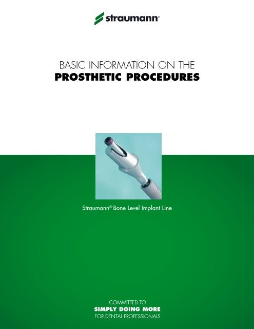
BASIC INFORMATION ON THE<br />
pros<strong>the</strong>tic <strong>procedures</strong><br />
<strong>Straumann</strong> ® B<strong>on</strong>e Level Implant Line
<strong>Straumann</strong> is <strong>the</strong> industrial partner of <strong>the</strong> Internati<strong>on</strong>al Team for Implantology (ITI)<br />
in <strong>the</strong> areas of research, development and educati<strong>on</strong>.
C<strong>on</strong>tent 1. <strong>Straumann</strong> ® B<strong>on</strong>e Level Implant –<br />
C<strong>on</strong>fidence at b<strong>on</strong>e level 3<br />
2. General <str<strong>on</strong>g>informati<strong>on</strong></str<strong>on</strong>g> 4<br />
2.1 CrossFit C<strong>on</strong>necti<strong>on</strong> 4<br />
2.2 Pros<strong>the</strong>tic opti<strong>on</strong>s 6<br />
2.3 Abutment overview 8<br />
2.4 Coding 10<br />
3. Preoperative planning 12<br />
3.1 Wax-up/Set-up 12<br />
3.2 X-ray template with reference spheres 12<br />
3.3 Custom-made drill template 13<br />
3.4 Thermoplastic drill template 14<br />
4. Soft tissue management 15<br />
4.1 Soft tissue management soluti<strong>on</strong>s 15<br />
4.2 Prefabricated Healing Abutment 16<br />
4.3 Customizable Healing Abutment 19<br />
4.4 Temporary Abutment 21<br />
5. Impressi<strong>on</strong> taking 28<br />
5.1 Opti<strong>on</strong>s for impressi<strong>on</strong> taking 28<br />
5.2 Open tray impressi<strong>on</strong> 29<br />
5.3 Closed tray impressi<strong>on</strong> 33<br />
5.4 Bite registrati<strong>on</strong> 37<br />
6. Restorati<strong>on</strong> 39<br />
6.1 CrossFit PLAN Set/PLAN Abutment 39<br />
6.2 Anatomic (and Meso) Abutment 42<br />
6.3 Gold Abutment for crown 49<br />
6.4 Gold Abutment for bridge 61<br />
6.5 Customized CAD/CAM Abutment 71<br />
6.6 Cementable Abutment 81<br />
6.7 Multi-Base Abutment 96<br />
6.8 Abutment for bars 114<br />
6.9 LOCATOR ® Abutment 124<br />
7. Aids and instruments 140<br />
7.1 SCS Screwdriver 140<br />
7.2 Polishing Aid 141<br />
7.3 Ratchet and Torque C<strong>on</strong>trol Device 142<br />
7.4 Assembling <strong>the</strong> Ratchet and <strong>the</strong> Torque C<strong>on</strong>trol Device 144<br />
7.5 Tightening an abutment to 35 Ncm 146<br />
8. About sterilizati<strong>on</strong> 148<br />
9. Important guidelines 149<br />
10. Index 150
Purpose of this guide<br />
This guide describes <strong>the</strong> essential steps required for <strong>the</strong> fabricati<strong>on</strong> and<br />
inserti<strong>on</strong> of pros<strong>the</strong>tic restorati<strong>on</strong>s for <strong>Straumann</strong> ® B<strong>on</strong>e Level implants.<br />
For detailed <str<strong>on</strong>g>informati<strong>on</strong></str<strong>on</strong>g> regarding implantati<strong>on</strong> and soft tissue management see<br />
“Basic <str<strong>on</strong>g>informati<strong>on</strong></str<strong>on</strong>g> <strong>on</strong> <strong>the</strong> surgical <strong>procedures</strong> with <strong>the</strong> <strong>Straumann</strong> ® Dental Implant<br />
System” (Art. No. USLIT100).<br />
Note<br />
Different <strong>procedures</strong> apply for dental technicians and prosthod<strong>on</strong>tists. Such<br />
<strong>procedures</strong> are marked with a color code in <strong>the</strong> respective chapters of this guide:<br />
88<br />
88<br />
Lab procedure<br />
Pros<strong>the</strong>tic procedure<br />
2<br />
Purpose of this guide
1. <strong>Straumann</strong> ® B<strong>on</strong>e Level Implant –<br />
c<strong>on</strong>fidence at b<strong>on</strong>e level<br />
The <strong>Straumann</strong> ® B<strong>on</strong>e Level Implant provides you with a soluti<strong>on</strong> for all b<strong>on</strong>e level treatments, with <strong>Straumann</strong> expertise<br />
and quality built in. The implant design is based <strong>on</strong> <strong>the</strong> latest technology and scientific research in implant dentistry.<br />
<strong>Straumann</strong>’s b<strong>on</strong>e level implant respects five key biological principles, is designed to provide predictable es<strong>the</strong>tic results<br />
and offers simple handling in a variety of indicati<strong>on</strong>s.<br />
C<strong>on</strong>sistent Emergence Profiles<br />
Experience simplified soft tissue<br />
management from start to finish<br />
CrossFit C<strong>on</strong>necti<strong>on</strong><br />
B<strong>on</strong>e C<strong>on</strong>trol Design <br />
Feel <strong>the</strong> fit of <strong>the</strong> self-guiding c<strong>on</strong>necti<strong>on</strong><br />
Designed to optimize crestal b<strong>on</strong>e preservati<strong>on</strong><br />
though adherence to biological<br />
principles<br />
B<strong>on</strong>e C<strong>on</strong>trol Design<br />
The unique B<strong>on</strong>e C<strong>on</strong>trol Design is<br />
based <strong>on</strong> key biological principles and<br />
thorough scientific research to support<br />
crestal b<strong>on</strong>e preservati<strong>on</strong> and stable<br />
soft tissue margins. It features <strong>the</strong> following<br />
strengths:<br />
Fast osseointegrati<strong>on</strong> with <strong>the</strong><br />
SLActive ® surface technology<br />
Transmissi<strong>on</strong> of forces into <strong>the</strong> b<strong>on</strong>e<br />
through <strong>the</strong> biomechanical implant<br />
design<br />
C<strong>on</strong>siderati<strong>on</strong> of <strong>the</strong> biological<br />
distance with a horiz<strong>on</strong>tal distance<br />
of microgap to b<strong>on</strong>e<br />
Minimal micromovement through a<br />
c<strong>on</strong>ical c<strong>on</strong>necti<strong>on</strong><br />
C<strong>on</strong>sistent Emergence Profiles<br />
The pros<strong>the</strong>tic comp<strong>on</strong>ents of <strong>the</strong><br />
<strong>Straumann</strong> ® B<strong>on</strong>e Level implant line are<br />
designed to facilitate highly es<strong>the</strong>tic restorati<strong>on</strong>s<br />
that mimic natural teeth. These<br />
implant line comp<strong>on</strong>ents, designed to<br />
match <strong>the</strong> abutment profiles, allow you<br />
to easily attain es<strong>the</strong>tic results through<br />
soft tissue management.<br />
CrossFit C<strong>on</strong>necti<strong>on</strong><br />
The pros<strong>the</strong>tic c<strong>on</strong>necti<strong>on</strong> is intuitive,<br />
self-guiding and easy to grasp. The<br />
CrossFit C<strong>on</strong>necti<strong>on</strong>:<br />
Provides a clear-cut inserti<strong>on</strong> through<br />
<strong>the</strong> guidance by 4 grooves and <strong>the</strong><br />
deep, c<strong>on</strong>ical c<strong>on</strong>necti<strong>on</strong><br />
Prevents rotati<strong>on</strong> through orthog<strong>on</strong>al<br />
fit between implant and abutment<br />
Gives pros<strong>the</strong>tic flexibility with<br />
mechanical l<strong>on</strong>g-term stability<br />
through its c<strong>on</strong>ical c<strong>on</strong>necti<strong>on</strong><br />
1. <strong>Straumann</strong> ® B<strong>on</strong>e Level Implant – <strong>Straumann</strong> expertise applied at b<strong>on</strong>e level<br />
3
2. General <str<strong>on</strong>g>informati<strong>on</strong></str<strong>on</strong>g><br />
2.1 crossFit c<strong>on</strong>necti<strong>on</strong><br />
The <strong>Straumann</strong> ® B<strong>on</strong>e Level Implant features an intuitive implant-abutment<br />
c<strong>on</strong>necti<strong>on</strong> that is self-guiding and designed<br />
to enable simple positi<strong>on</strong>ing. The new c<strong>on</strong>necti<strong>on</strong> is designed<br />
to allow clear-cut inserti<strong>on</strong> with all comp<strong>on</strong>ents to<br />
provide outstanding protecti<strong>on</strong> against rotati<strong>on</strong>, as well as<br />
l<strong>on</strong>g-term stability.<br />
Precisi<strong>on</strong> and simplicity: 4 grooves<br />
The CrossFit C<strong>on</strong>necti<strong>on</strong> features 4 grooves for<br />
<strong>the</strong> repositi<strong>on</strong>ing of pros<strong>the</strong>tic comp<strong>on</strong>ents. This c<strong>on</strong>figurati<strong>on</strong><br />
is designed for:<br />
simple implant alignment<br />
clear-cut and guided comp<strong>on</strong>ent inserti<strong>on</strong><br />
flexibility in <strong>the</strong> placement of angled pros<strong>the</strong>tic<br />
comp<strong>on</strong>ents<br />
designed to prevent rotati<strong>on</strong> by<br />
orthog<strong>on</strong>al implant-abutment fit<br />
Figure 1: The internal c<strong>on</strong>necti<strong>on</strong> viewed from above<br />
shows <strong>the</strong> 4 internal grooves.<br />
Figure 2: Abutment inserti<strong>on</strong>, step 1.<br />
The abutment is placed <strong>on</strong> <strong>the</strong> 4 grooves in <strong>the</strong> implant.<br />
4<br />
2. General <str<strong>on</strong>g>informati<strong>on</strong></str<strong>on</strong>g>
Figure 3a: Abutment inserti<strong>on</strong>, step 2.<br />
The abutment is turned until it is aligned with <strong>the</strong> 4 implant<br />
grooves.<br />
Figure 3b: Abutment inserti<strong>on</strong>, step 3.<br />
The abutment <strong>the</strong>n falls into its final positi<strong>on</strong>.<br />
Figure 4: The CrossFit c<strong>on</strong>necti<strong>on</strong> provides an orthog<strong>on</strong>al<br />
fit between <strong>the</strong> implant and abutment.<br />
Reliability and flexibility: C<strong>on</strong>ical c<strong>on</strong>necti<strong>on</strong><br />
The CrossFit C<strong>on</strong>necti<strong>on</strong> features a c<strong>on</strong>e with improved mechanical properties,<br />
providing more flexibility for pros<strong>the</strong>tic treatments.<br />
The c<strong>on</strong>ical pros<strong>the</strong>tic c<strong>on</strong>necti<strong>on</strong> provides:<br />
reduced micromovements and minimized microgap<br />
outstanding mechanical stability and optimized stress distributi<strong>on</strong><br />
exact implant-abutment fit<br />
simplified impressi<strong>on</strong> taking with divergently positi<strong>on</strong>ed implants<br />
2. General <str<strong>on</strong>g>informati<strong>on</strong></str<strong>on</strong>g><br />
5
2.2 Pros<strong>the</strong>tic opti<strong>on</strong>s<br />
Gold Abutment, for crown<br />
Screw-retained<br />
CAD/CAM Customized Ceramic<br />
Abutment<br />
Single crown<br />
Anatomic Abutment<br />
Meso Abutment<br />
Gold Abutment, for crown<br />
Cement-retained<br />
CAD/CAM Customized Ceramic<br />
Abutment<br />
CAD/CAM Customized Titanium<br />
Abutment<br />
Cementable Abutment<br />
Screw-retained<br />
Gold Abutment, for bridge<br />
Multi-Base Abutment<br />
Bridge<br />
Anatomic Abutment<br />
Meso Abutment<br />
Gold Abutment, for crown<br />
Cement-retained<br />
CAD/CAM Customized Ceramic<br />
Abutment<br />
CAD/CAM Customized Titanium<br />
Abutment<br />
Cementable Abutment<br />
6<br />
2. General <str<strong>on</strong>g>informati<strong>on</strong></str<strong>on</strong>g>
Retentive anchor<br />
LOCATOR ® Abutment<br />
Abutment for Bar, Gold<br />
Removable overdenture<br />
Bar<br />
Abutment for Bar, Titanium<br />
Multi-Base Abutment<br />
Customized bar<br />
Gold Abutment, for bridge<br />
Anatomic Abutment<br />
Telescope<br />
Meso Abutment<br />
Gold Abutment, for crown<br />
2. General <str<strong>on</strong>g>informati<strong>on</strong></str<strong>on</strong>g><br />
7
2.3 Abutment Overview<br />
Anatomic<br />
Abutment<br />
Meso<br />
Abutment<br />
Gold Abutment,<br />
for crown<br />
Gold Abutment,<br />
for bridge<br />
CAD/CAM<br />
Customized Ceramic<br />
Abutment<br />
Single crown<br />
Screw-retained • •<br />
Cement-retained • • • •<br />
Bridge<br />
Screw-retained<br />
•<br />
Cement-retained • • • •<br />
Removable overdenture<br />
Telescope • • •<br />
Bar<br />
•<br />
Impressi<strong>on</strong><br />
Implant level • • • • •<br />
Abutment level<br />
Material* Titanium Titanium Ceramicor ® Ceramicor ® Zirc<strong>on</strong>ia<br />
Page 42 42 49 61 71<br />
*See <str<strong>on</strong>g>informati<strong>on</strong></str<strong>on</strong>g> <strong>on</strong> sterilizati<strong>on</strong> c<strong>on</strong>diti<strong>on</strong>s <strong>on</strong> page 148.<br />
Ceramicor ® is a registered trademark of Cendres & Métaux SA<br />
(Biel-Bienne, Switzerland)<br />
8<br />
2. General <str<strong>on</strong>g>informati<strong>on</strong></str<strong>on</strong>g>
CAD/CAM Customized<br />
Titanium<br />
Abutment<br />
Cementable<br />
Abutment<br />
Multi-Base<br />
Abutment<br />
Abutment for<br />
Bar, Gold<br />
Abutment for<br />
Bar, Titanium<br />
LOCATOR ® Abutment<br />
• •<br />
• •<br />
•<br />
• • •<br />
• • • • • •<br />
• • •<br />
Titanium Titanium Titanium alloy Ceramicor ® Titanium Ti alloy<br />
71 81 96 114 114 124<br />
2. General <str<strong>on</strong>g>informati<strong>on</strong></str<strong>on</strong>g><br />
9
2.4 Coding<br />
The <strong>Straumann</strong> ® B<strong>on</strong>e Level Implant line is color-coded and c<strong>on</strong>tains laser markings, enabling quick and precise identificati<strong>on</strong><br />
of sec<strong>on</strong>dary parts, surgical instruments and auxiliaries. This c<strong>on</strong>cept simplifies <strong>the</strong> communicati<strong>on</strong> between all individuals<br />
involved in <strong>the</strong> treatment process.<br />
The following scheme illustrates <strong>the</strong> above menti<strong>on</strong>ed approach:<br />
C<strong>on</strong>necti<strong>on</strong> Implant Ø Instruments Implant Closure screw<br />
Narrow CrossFit <br />
(NC)<br />
3.3 mm<br />
Regular CrossFit <br />
(RC)<br />
4.1 mm<br />
4.8 mm<br />
Laser marked (NC/RC) • •<br />
Color-coded •<br />
10<br />
2. General <str<strong>on</strong>g>informati<strong>on</strong></str<strong>on</strong>g>
Healing abutment Impressi<strong>on</strong> post Implant analog Temporary<br />
abutment<br />
Sec<strong>on</strong>dary part<br />
abutment<br />
• •<br />
• • • • •<br />
Screw head<br />
Screw head<br />
*See <str<strong>on</strong>g>informati<strong>on</strong></str<strong>on</strong>g> <strong>on</strong> sterilizati<strong>on</strong> c<strong>on</strong>diti<strong>on</strong>s <strong>on</strong> page 148.<br />
2. General <str<strong>on</strong>g>informati<strong>on</strong></str<strong>on</strong>g><br />
11
3. Preoperative planning<br />
Careful treatment planning is of utmost importance. A comprehensive pre-implantati<strong>on</strong><br />
diagnosis, evaluati<strong>on</strong> and plan are an absolute prerequisite to ensure treatment<br />
success. The implant forms <strong>the</strong> apical extensi<strong>on</strong> of <strong>the</strong> restorati<strong>on</strong> and serves<br />
as <strong>the</strong> planning basis for <strong>the</strong> surgical procedure, ultimately achieving a specific<br />
pros<strong>the</strong>tic result. Close communicati<strong>on</strong> between <strong>the</strong> patient, dentist and dental<br />
technician is imperative to achieve excellent implant-borne restorati<strong>on</strong>s.<br />
3.1 Wax-up/Set-up<br />
To determine <strong>the</strong> topographical situati<strong>on</strong>, axial orientati<strong>on</strong><br />
and choice of implants, making a wax-up/set up using <strong>the</strong><br />
previously prepared study cast is recommended. Subsequently,<br />
<strong>the</strong> type of superstructure can be defined. The waxup/set-up<br />
can later be used as <strong>the</strong> basis for a custom-made<br />
X-ray or drill template and for a temporary restorati<strong>on</strong>.<br />
Abutments should always be loaded axially. Ideally, <strong>the</strong><br />
l<strong>on</strong>g axis of <strong>the</strong> implant is aligned with <strong>the</strong> cusps of <strong>the</strong><br />
opposing tooth. Extreme cusp formati<strong>on</strong> should be avoided<br />
as this can lead to unphysiological loading.<br />
3.2 X-ray template with reference spheres<br />
To accurately determine b<strong>on</strong>e availability, <strong>the</strong> use of an X-<br />
ray template with X-ray reference spheres is recommended.<br />
First, mark <strong>the</strong> proposed implant positi<strong>on</strong>s <strong>on</strong> <strong>the</strong> study cast.<br />
Then, fix <strong>the</strong> X-ray reference spheres at <strong>the</strong> marked points<br />
and make <strong>the</strong> vacuum-formed template with <strong>the</strong> spheres. The<br />
subsequently taken X-ray or computer tomography (CT) scan<br />
provides <str<strong>on</strong>g>informati<strong>on</strong></str<strong>on</strong>g> <strong>on</strong> b<strong>on</strong>e availability, quality and mucosal<br />
thickness. Based <strong>on</strong> <strong>the</strong>se properties, <strong>the</strong> exact implant<br />
positi<strong>on</strong>s, number of implants, diameters and lengths can be<br />
determined.<br />
The X-ray reference sphere has a diameter of<br />
5 mm. The image of <strong>the</strong> sphere <strong>on</strong> <strong>the</strong> X-ray<br />
provides <strong>the</strong> reference value for <strong>the</strong> magnificati<strong>on</strong><br />
scale.<br />
12<br />
3. Preoperative planning
3.3 Custom-made drill template<br />
A custom-made drill template can facilitate planning and <strong>the</strong> preparati<strong>on</strong> of <strong>the</strong> implant bed and enables precise use of <strong>the</strong><br />
cutting instruments. The desired pros<strong>the</strong>tic result should serve as <strong>the</strong> focus throughout all treatment planning stages.<br />
With <strong>the</strong>se comp<strong>on</strong>ents, a surgical drill template can be produced in <strong>the</strong> usual manner:<br />
Art. No. Article Dimensi<strong>on</strong>s<br />
049.810V4 Drill sleeve with collar height 10 mm<br />
outside Ø 3.5 mm<br />
inside Ø 2.3 mm<br />
049.818V4 Stepped pin for 049.810 height 16 mm<br />
Ø 2.2/3.5 mm<br />
049.816V4 Pin for 049.810 height 16 mm,<br />
Ø 2.2 mm<br />
049.817V4 Pin for 049.810 height 10 mm,<br />
Ø 2.2 mm<br />
049.819V4 Pin for 049.810 height 16 mm,<br />
Ø 3.5 mm<br />
The <strong>Straumann</strong> brochure “Basic <str<strong>on</strong>g>informati<strong>on</strong></str<strong>on</strong>g> <strong>on</strong> <strong>the</strong> surgical procedure with <strong>the</strong> <strong>Straumann</strong> ® Dental Implant<br />
System“ (USLIT 100) c<strong>on</strong>tains two fabricati<strong>on</strong> methods with step by step instructi<strong>on</strong>s.<br />
Vacuum-formed template with integral pins as<br />
X-ray reference<br />
Vacuum-formed template with integrated drill<br />
sleeve as drilling template<br />
3. Preoperative planning<br />
13
3.4 Thermoplastic drill template<br />
Art. No. Article Dimensi<strong>on</strong>s Material<br />
040.526 Thermoplastic drill templates set, single tooth, c<strong>on</strong>tents:<br />
Thermoplastic drill template for<br />
single-tooth sites (V5)<br />
sleeve height 10 mm,<br />
inner Ø 2.3 mm<br />
titanium/<br />
polymer<br />
Guide pin (V5) length 20 mm, Ø 2.3 mm stainless steel<br />
040.527 Thermoplastic drill templates set, free-end situati<strong>on</strong>, c<strong>on</strong>tents:<br />
Drill for dental laboratory Ø 2.3 mm steel<br />
Thermoplastic drill template for<br />
free-end situati<strong>on</strong>s (V5)<br />
sleeve height 10 mm,<br />
inner Ø 2.3 mm<br />
titanium/<br />
polymer<br />
Guide pin (V5) length 20 mm, Ø 2.3 mm stainless steel<br />
Drill for dental laboratory Ø 2.3 mm steel<br />
V5 = 5 comp<strong>on</strong>ents per pack<br />
Drill a hole in <strong>the</strong> previously determined implant positi<strong>on</strong> and axis in <strong>the</strong> plaster anatomic cast. Then insert<br />
<strong>the</strong> pin into <strong>the</strong> prepared site in order to check <strong>the</strong> implant positi<strong>on</strong>. Subsequently, heat <strong>the</strong> template<br />
in water until it is soft and transparent. Place <strong>the</strong> template <strong>on</strong> <strong>the</strong> guide pin and press it <strong>on</strong>to <strong>the</strong> plaster<br />
teeth. After it has cooled and been disinfected, <strong>the</strong> <strong>the</strong>rmoplastic drill template determines exactly how <strong>the</strong><br />
pilot drill (Ø 2.2 mm) is to be guided.<br />
Drill hole template for single tooth situati<strong>on</strong><br />
Drill hole template for free end situati<strong>on</strong><br />
14 3. Preoperative planning
4. Soft tissue management<br />
The <strong>Straumann</strong> ® B<strong>on</strong>e Level Implant line emphasizes es<strong>the</strong>tic c<strong>on</strong>siderati<strong>on</strong>s, offering tailor-made soluti<strong>on</strong>s<br />
that allow for natural soft tissue shaping and maintenance in a variety of indicati<strong>on</strong>s. A versatile portfolio<br />
of healing and temporary abutments is available, including customizable products made of polymer for<br />
easy and quick processing.<br />
4.1 Soft tissue management soluti<strong>on</strong>s<br />
Healing Abutment<br />
Temporary Abutment<br />
Prefabricated healing abutment<br />
(titanium)<br />
p. 16–18<br />
Customizable healing abutment<br />
(polymer)<br />
p. 19–20<br />
(polymer with titanium inlay)<br />
p. 21–27<br />
4. Soft tissue management<br />
15
4.2 Prefabricated healing abutment<br />
Intended use<br />
Soft tissue management<br />
Closure of implant c<strong>on</strong>necti<strong>on</strong> for submerged and n<strong>on</strong>-submerged healing<br />
Characteristics<br />
Simple<br />
One-piece design<br />
Color-coded and laser-marked<br />
Anatomically shaped emergence profiles, matching impressi<strong>on</strong> post and final<br />
abutments<br />
Reliable<br />
CrossFit c<strong>on</strong>necti<strong>on</strong><br />
88 Pros<strong>the</strong>tic procedure: p. 17–18<br />
16<br />
4. Soft tissue management
Pros<strong>the</strong>tic procedure<br />
4.2.1 Prefabricated Healing Abutment – Pros<strong>the</strong>tic procedure<br />
1<br />
Step 1 – Inserti<strong>on</strong><br />
Insert <strong>the</strong> healing abutment with <strong>the</strong> SCS screwdriver. The<br />
fricti<strong>on</strong> fit secures <strong>the</strong> healing abutment to <strong>the</strong> instrument<br />
during inserti<strong>on</strong> and ensures safe handling.<br />
Hand-tighten <strong>the</strong> healing abutment. The c<strong>on</strong>e-in-c<strong>on</strong>e<br />
design provides a tight c<strong>on</strong>necti<strong>on</strong> between <strong>the</strong> two<br />
comp<strong>on</strong>ents.<br />
2<br />
Step 2 – Wound closure<br />
Adapt <strong>the</strong> soft tissue and suture it back tightly around <strong>the</strong><br />
abutment.<br />
4. Soft tissue management<br />
17
Pros<strong>the</strong>tic procedure<br />
Opti<strong>on</strong>al: Bottle-shaped and customizable healing abutment<br />
The bottle-shaped healing abutment pre-shapes <strong>the</strong> soft tissue<br />
by allowing for a slight excess of mucosa to accumulate<br />
during healing. The inserti<strong>on</strong> of <strong>the</strong> final restorati<strong>on</strong> pushes<br />
<strong>the</strong> formed tissue outward, supporting <strong>the</strong> creati<strong>on</strong> of naturally<br />
shaped peri-implant soft tissue.<br />
The customizable healing abutment allows for individual soft<br />
tissue management.<br />
Note<br />
Do not use <strong>the</strong> customizable healing abutment for l<strong>on</strong>ger<br />
than 6 m<strong>on</strong>ths.<br />
Healing abutments are delivered n<strong>on</strong>-sterile and must be<br />
sterilized prior to use (see instructi<strong>on</strong>s, p. 148).<br />
18<br />
4. Soft tissue management
4.3 Customizable Healing Abutment<br />
Intended use<br />
Individual soft tissue management for es<strong>the</strong>tic cases<br />
Closure of implant c<strong>on</strong>necti<strong>on</strong> during healing phase<br />
Characteristics<br />
Simple<br />
Polymer material allows for easy and quick chair-side modificati<strong>on</strong><br />
Easy to achieve es<strong>the</strong>tics due to gingiva-colored and modifiable polymer<br />
material<br />
Reliable<br />
CrossFit C<strong>on</strong>necti<strong>on</strong><br />
Note<br />
Do not use in <strong>the</strong> mouth for l<strong>on</strong>ger than 6 m<strong>on</strong>ths<br />
88 Pros<strong>the</strong>tic procedure: p. 20<br />
4. Soft tissue management<br />
19
Pros<strong>the</strong>tic procedure<br />
4.3.1 Customizable Healing Abutment – Pros<strong>the</strong>tic procedure<br />
1a<br />
Step 1 – Customizing<br />
Individualize <strong>the</strong> healing abutment <strong>on</strong> an analog, in<br />
accordance with <strong>the</strong> mouth situati<strong>on</strong>. Heatless wheels and<br />
new cross-too<strong>the</strong>d millers are recommended for grinding.<br />
1b<br />
p p To avoid smearing of <strong>the</strong> polymer, adjust <strong>the</strong> bur<br />
speed properly (low rpm number, minimal pressure).<br />
Step 2 – Inserti<strong>on</strong><br />
Hand-tighten <strong>the</strong> healing abutment in <strong>the</strong> implant with <strong>the</strong><br />
SCS screwdriver and temporarily seal <strong>the</strong> screw channel<br />
(e.g., with composite).<br />
20<br />
4. Soft tissue management
4.4 Temporary Abutment<br />
Intended use<br />
Individual soft tissue management for es<strong>the</strong>tic cases<br />
Screw- or cement-retained temporary crowns<br />
Cement-retained temporary bridges<br />
Characteristics<br />
Simple<br />
Polymer material allows for easy and quick chair-side modificati<strong>on</strong><br />
Easy to achieve es<strong>the</strong>tics due to tooth-colored and modifiable polymer material<br />
Reliable<br />
Precise fit and high stability due to reinforcement with titanium inlay<br />
CrossFit C<strong>on</strong>necti<strong>on</strong><br />
Note<br />
Do not use in <strong>the</strong> mouth for l<strong>on</strong>ger than 6 m<strong>on</strong>ths<br />
Place temporary restorati<strong>on</strong> out of occlusi<strong>on</strong><br />
The NC temporary abutment may be modified by a maximum of 6.0 mm vertically<br />
and 0.5 mm laterally. The RC temporary abutment may be modified by a<br />
maximum of 6.0 mm vertically and 1.0 mm laterally.<br />
88 Lab procedure: p. 22–27<br />
88 Pros<strong>the</strong>tic procedure: p. 22–27<br />
4. Soft tissue management<br />
21
Lab procedure<br />
Pros<strong>the</strong>tic procedure<br />
4.4.1 Temporary Abutment – Procedure<br />
Opti<strong>on</strong> A: Screw-retained temporary crown<br />
1a<br />
Step 1 – Customizing<br />
Individualize <strong>the</strong> temporary abutment <strong>on</strong> an analog, in<br />
accordance with <strong>the</strong> mouth situati<strong>on</strong>. Heatless wheels and<br />
new cross-too<strong>the</strong>d millers are recommended for grinding.<br />
To avoid smearing of <strong>the</strong> polymer, adjust <strong>the</strong> bur speed<br />
properly (low rpm number, minimal pressure).<br />
1b<br />
Note<br />
For optimal adhesi<strong>on</strong> of <strong>the</strong> temporary veneering material,<br />
roughen or sandblast <strong>the</strong> upper secti<strong>on</strong> of <strong>the</strong> abutment or<br />
integrate a means of retenti<strong>on</strong>.<br />
22<br />
4. Soft tissue management
Lab procedure<br />
Pros<strong>the</strong>tic procedure<br />
2a<br />
Step 2 – First inserti<strong>on</strong><br />
Hand-tighten <strong>the</strong> temporary abutment in <strong>the</strong> implant/<br />
implant analog with <strong>the</strong> SCS screwdriver and temporarily<br />
seal <strong>the</strong> screw channel (e.g., with cott<strong>on</strong>).<br />
2b<br />
2c<br />
p p Use a standard technique to fabricate <strong>the</strong> temporary<br />
restorati<strong>on</strong> (e.g., prefabricated crown form or vacuumformed<br />
sheet technique, as shown here).<br />
2d<br />
4. Soft tissue management<br />
23
Lab procedure<br />
Pros<strong>the</strong>tic procedure<br />
3<br />
Step 3 – Finishing<br />
Remove excess acrylic, reopen <strong>the</strong> screw channel and<br />
finish <strong>the</strong> temporary restorati<strong>on</strong>.<br />
4<br />
Step 4 – Final inserti<strong>on</strong><br />
Clean <strong>the</strong> polished temporary restorati<strong>on</strong>, place it <strong>on</strong><br />
<strong>the</strong> implant and tighten <strong>the</strong> screw with a torque between<br />
15 Ncm and 35 Ncm using <strong>the</strong> SCS screwdriver, al<strong>on</strong>g<br />
with <strong>the</strong> ratchet and <strong>the</strong> torque c<strong>on</strong>trol device (see instructi<strong>on</strong>s<br />
in chapter 7.5, p. 146).<br />
Cover <strong>the</strong> screw head with absorbent cott<strong>on</strong> or gutta<br />
percha and seal <strong>the</strong> screw channel with temporary<br />
veneering material (e.g., composite).<br />
24<br />
4. Soft tissue management
Lab procedure<br />
Pros<strong>the</strong>tic procedure<br />
Opti<strong>on</strong> B: Cement-retained temporary crown<br />
1a<br />
Step 1 – Customizing<br />
Individualize <strong>the</strong> temporary abutment <strong>on</strong> an analog, in<br />
accordance with <strong>the</strong> mouth situati<strong>on</strong>. Heatless wheels and<br />
new cross-too<strong>the</strong>d millers are recommended for grinding.<br />
To avoid smearing of <strong>the</strong> polymer, adjust <strong>the</strong> bur speed<br />
properly (low rpm number, minimal pressure).<br />
1b<br />
Note<br />
For optimal adhesi<strong>on</strong> of <strong>the</strong> cement-retained temporary<br />
crown, roughen or sandblast <strong>the</strong> upper secti<strong>on</strong> of <strong>the</strong><br />
abutment.<br />
4. Soft tissue management<br />
25
Lab procedure<br />
Pros<strong>the</strong>tic procedure<br />
2a<br />
Step 2 – Fabricating <strong>the</strong> cement-retained temporary<br />
single crown<br />
Use a standard procedure to fabricate <strong>the</strong> cement- retained<br />
single crown (e.g., grind out a prefabricated plastic tooth).<br />
2b<br />
26<br />
4. Soft tissue management
Lab procedure<br />
Pros<strong>the</strong>tic procedure<br />
3a<br />
Step 3 – Placing <strong>the</strong> customized abutment<br />
Place <strong>the</strong> abutment <strong>on</strong> <strong>the</strong> implant and tighten <strong>the</strong> screw<br />
with a torque between 15 Ncm and 35 Ncm using <strong>the</strong><br />
SCS screwdriver, al<strong>on</strong>g with <strong>the</strong> ratchet and <strong>the</strong> torque<br />
c<strong>on</strong>trol device (see instructi<strong>on</strong>s in chapter 7.5, p. 146).<br />
3b<br />
Cover <strong>the</strong> screw head with absorbent cott<strong>on</strong> or gutta<br />
percha and seal <strong>the</strong> screw channel temporarily (e.g., with<br />
absorbent cott<strong>on</strong>).<br />
4<br />
Step 4 – Cementing <strong>the</strong> temporary single crown<br />
Coat <strong>the</strong> internal c<strong>on</strong>figurati<strong>on</strong> of <strong>the</strong> crown with temporary<br />
cement and cement it <strong>on</strong> <strong>the</strong> temporary abutment.<br />
4. Soft tissue management<br />
27
5. impressi<strong>on</strong> taking<br />
5.1 Opti<strong>on</strong>s for impressi<strong>on</strong> taking<br />
Impressi<strong>on</strong>s for <strong>the</strong> <strong>Straumann</strong> ® B<strong>on</strong>e Level Implant can be taken by ei<strong>the</strong>r of <strong>the</strong> following two<br />
<strong>procedures</strong>:<br />
Open tray technique<br />
Closed tray technique<br />
p. 29–32 p. 33–36<br />
<strong>Straumann</strong> ® B<strong>on</strong>e Level Implant<br />
The technique used depends up<strong>on</strong> <strong>the</strong> user’s preference and <strong>the</strong> clinical situati<strong>on</strong>. Both techniques are<br />
described in <strong>the</strong> following chapters.<br />
28<br />
5. Impressi<strong>on</strong> taking
5.2 Open tray impressi<strong>on</strong><br />
Intended use<br />
Open tray impressi<strong>on</strong> technique<br />
Characteristics<br />
Simple<br />
Color-coded comp<strong>on</strong>ents corresp<strong>on</strong>d to pros<strong>the</strong>tic c<strong>on</strong>necti<strong>on</strong><br />
Slender emergence profile accommodates space limitati<strong>on</strong>s<br />
Guide screw can be tightened by hand or with <strong>the</strong> SCS screwdriver<br />
Reliable<br />
High precisi<strong>on</strong> impressi<strong>on</strong> comp<strong>on</strong>ents replicate <strong>the</strong> intraoral situati<strong>on</strong><br />
Clear-cut tactile resp<strong>on</strong>se from <strong>the</strong> pros<strong>the</strong>tic c<strong>on</strong>necti<strong>on</strong> verifies proper seating<br />
of comp<strong>on</strong>ents<br />
Note<br />
Open tray impressi<strong>on</strong> procedure requires a custom-made tray with perforati<strong>on</strong>s.<br />
Impressi<strong>on</strong> posts are intended for single use <strong>on</strong>ly, to ensure optimal fit and<br />
precise impressi<strong>on</strong> taking for each patient.<br />
88 Pros<strong>the</strong>tic procedure: p. 30–31<br />
88 Lab procedure: p. 32<br />
5. Impressi<strong>on</strong> taking<br />
29
Pros<strong>the</strong>tic procedure<br />
5.2.1 Open tray impressi<strong>on</strong> – Pros<strong>the</strong>tic procedure<br />
1<br />
Step 1 – Positi<strong>on</strong>ing <strong>the</strong> impressi<strong>on</strong> post<br />
Ensure sufficient access to <strong>the</strong> implant site in order<br />
to avoid pinching of <strong>the</strong> gingival tissue. Be aware<br />
that <strong>the</strong> sulcus may collapse rapidly <strong>on</strong>ce <strong>the</strong> healing<br />
comp<strong>on</strong>ents have been removed.<br />
Clean <strong>the</strong> internal c<strong>on</strong>figurati<strong>on</strong> of <strong>the</strong> implant thoroughly<br />
prior to <strong>the</strong> impressi<strong>on</strong> procedure.<br />
Place <strong>the</strong> impressi<strong>on</strong> post accurately into <strong>the</strong> implant and<br />
hand-tighten <strong>the</strong> guide screw.<br />
In situati<strong>on</strong>s where occlusal space is limited, <strong>the</strong> length of<br />
<strong>the</strong> impressi<strong>on</strong> post can be reduced by <strong>on</strong>e retenti<strong>on</strong> ring<br />
after <strong>the</strong> guide screw has been removed.<br />
30<br />
5. Impressi<strong>on</strong> taking
Pros<strong>the</strong>tic procedure<br />
2a<br />
Step 2 – Impressi<strong>on</strong> taking<br />
Make perforati<strong>on</strong>s in <strong>the</strong> custom-made impressi<strong>on</strong> tray<br />
(light cured resin) according to <strong>the</strong> individual situati<strong>on</strong> so<br />
that <strong>the</strong> positi<strong>on</strong>ing screw of <strong>the</strong> impressi<strong>on</strong> post sticks out.<br />
2b<br />
p p Take <strong>the</strong> impressi<strong>on</strong> using an elastomeric impressi<strong>on</strong><br />
material (polyvinyl siloxane or polye<strong>the</strong>r rubber).<br />
Note<br />
Due to its low tensile strength, hydrocolloid is not suitable for<br />
this applicati<strong>on</strong>.<br />
2c<br />
p p Uncover <strong>the</strong> screws before <strong>the</strong> material is cured.<br />
p p Once <strong>the</strong> material is cured, loosen <strong>the</strong> guide screws<br />
and remove <strong>the</strong> tray.<br />
2d<br />
5. Impressi<strong>on</strong> taking<br />
31
Lab procedure<br />
5.2.2 Open tray impressi<strong>on</strong> – Lab procedure<br />
1a<br />
Step 1 – Analog repositi<strong>on</strong>ing and fixing<br />
Repositi<strong>on</strong> and fix <strong>the</strong> analog in <strong>the</strong> impressi<strong>on</strong> using <strong>the</strong><br />
guide screw. To avoid inaccuracies when c<strong>on</strong>necting, <strong>the</strong><br />
analog must be positi<strong>on</strong>ed exactly in line with <strong>the</strong> grooves<br />
of <strong>the</strong> impressi<strong>on</strong> post before screwing in.<br />
1b<br />
1c<br />
Note<br />
When tightening <strong>the</strong> screw, grasp <strong>the</strong> retentive secti<strong>on</strong> of <strong>the</strong><br />
analog securely to prevent <strong>the</strong> impressi<strong>on</strong> post from rotating.<br />
This step is especially important when dealing with a shortened<br />
post.<br />
2<br />
Step 2 – Fabricating <strong>the</strong> master cast<br />
Fabricate <strong>the</strong> master cast using standard methods and<br />
type 4 dental st<strong>on</strong>e (DIN 6873). A gingival mask should<br />
always be used to ensure that <strong>the</strong> emergence profile of<br />
<strong>the</strong> crown is optimally c<strong>on</strong>toured.<br />
32<br />
5. Impressi<strong>on</strong> taking
5.3 Closed tray impressi<strong>on</strong><br />
Intended use<br />
Closed tray impressi<strong>on</strong> technique<br />
Characteristics<br />
Simple<br />
Color-coded comp<strong>on</strong>ents corresp<strong>on</strong>d to pros<strong>the</strong>tic c<strong>on</strong>necti<strong>on</strong><br />
Slender emergence profile to accommodate space limitati<strong>on</strong>s<br />
No additi<strong>on</strong>al preparati<strong>on</strong> (i.e., perforati<strong>on</strong>) of impressi<strong>on</strong> tray required<br />
Reliable<br />
High precisi<strong>on</strong> impressi<strong>on</strong> comp<strong>on</strong>ents replicate <strong>the</strong> intraoral situati<strong>on</strong><br />
Clear-cut tactile resp<strong>on</strong>se from <strong>the</strong> pros<strong>the</strong>tic c<strong>on</strong>necti<strong>on</strong> verifies proper seating<br />
of comp<strong>on</strong>ents<br />
Note<br />
Impressi<strong>on</strong> posts are intended for single use <strong>on</strong>ly, to ensure optimal fit and precise<br />
impressi<strong>on</strong> taking for each patient.<br />
88 Pros<strong>the</strong>tic procedure: p. 34–35<br />
88 Lab procedure: p. 36<br />
5. Impressi<strong>on</strong> taking<br />
33
Pros<strong>the</strong>tic procedure<br />
5.3.1 Closed tray impressi<strong>on</strong> – Pros<strong>the</strong>tic procedure<br />
1a<br />
Step 1 – Positi<strong>on</strong>ing <strong>the</strong> impressi<strong>on</strong> post<br />
Ensure sufficient access to <strong>the</strong> implant site in order<br />
to avoid pinching of <strong>the</strong> gingival tissue. Be aware<br />
that <strong>the</strong> sulcus may collapse rapidly <strong>on</strong>ce <strong>the</strong> healing<br />
comp<strong>on</strong>ents have been removed.<br />
Clean <strong>the</strong> internal c<strong>on</strong>figurati<strong>on</strong> of <strong>the</strong> implant thoroughly<br />
prior to <strong>the</strong> impressi<strong>on</strong> procedure.<br />
Place <strong>the</strong> impressi<strong>on</strong> post accurately into <strong>the</strong> implant and<br />
hand-tighten <strong>the</strong> guide screw with <strong>the</strong> SCS screwdriver.<br />
Note<br />
Ensure that <strong>the</strong> lateral planar areas of <strong>the</strong> post are facing<br />
mesial and distal.<br />
1b<br />
p p Place <strong>the</strong> polymer impressi<strong>on</strong> cap <strong>on</strong> top of <strong>the</strong><br />
fixed impressi<strong>on</strong> post. Ensure that <strong>the</strong> color of <strong>the</strong><br />
cap corresp<strong>on</strong>ds to <strong>the</strong> color of <strong>the</strong> positi<strong>on</strong>ing screw<br />
in <strong>the</strong> post and that <strong>the</strong> arrows are aligned in a<br />
p p buccal-lingual directi<strong>on</strong>.<br />
p p Push <strong>the</strong> impressi<strong>on</strong> cap in an apical directi<strong>on</strong> until it<br />
clicks. The impressi<strong>on</strong> cap is now firmly seated <strong>on</strong> <strong>the</strong><br />
impressi<strong>on</strong> post.<br />
34<br />
5. Impressi<strong>on</strong> taking
Pros<strong>the</strong>tic procedure<br />
2a<br />
Step 2 – Impressi<strong>on</strong> taking<br />
Take <strong>the</strong> impressi<strong>on</strong> using an elastomeric impressi<strong>on</strong><br />
material (polyvinyl siloxane or polye<strong>the</strong>r rubber).<br />
Note<br />
Due to its low tensile strength, hydrocolloid is not suitable for<br />
this applicati<strong>on</strong>.<br />
2b<br />
Once <strong>the</strong> material is cured, carefully remove <strong>the</strong> tray.<br />
The impressi<strong>on</strong> cap remains in <strong>the</strong> impressi<strong>on</strong> material and<br />
<strong>the</strong>refore is automatically pulled off from <strong>the</strong> impressi<strong>on</strong><br />
post with <strong>the</strong> removal of <strong>the</strong> tray.<br />
2c<br />
Unscrew and remove <strong>the</strong> impressi<strong>on</strong> post and send it with<br />
<strong>the</strong> impressi<strong>on</strong> tray to <strong>the</strong> dental technician.<br />
5. Impressi<strong>on</strong> taking<br />
35
Lab procedure<br />
5.3.2 Closed tray impressi<strong>on</strong> – Lab procedure<br />
1a<br />
Step 1 – Analog fixing and impressi<strong>on</strong> post<br />
repositi<strong>on</strong>ing<br />
Mount <strong>the</strong> impressi<strong>on</strong> post <strong>on</strong>to <strong>the</strong> analog using <strong>the</strong><br />
guide screw. To avoid inaccuracies when c<strong>on</strong>necting, <strong>the</strong><br />
analog must be positi<strong>on</strong>ed exactly in line with <strong>the</strong> grooves<br />
of <strong>the</strong> impressi<strong>on</strong> post before screwing it in.<br />
1b<br />
Note<br />
Ensure that <strong>the</strong> color code of <strong>the</strong> guide screw corresp<strong>on</strong>ds<br />
to <strong>the</strong> color code of <strong>the</strong> analog, and that <strong>the</strong> color code of<br />
<strong>the</strong> analog corresp<strong>on</strong>ds to <strong>the</strong> color code of <strong>the</strong> polymer<br />
cap in <strong>the</strong> impressi<strong>on</strong> material.<br />
1c<br />
Repositi<strong>on</strong> <strong>the</strong> impressi<strong>on</strong> post in <strong>the</strong> tray.<br />
Gently push <strong>the</strong> impressi<strong>on</strong> post until you feel <strong>the</strong> tactile<br />
resp<strong>on</strong>se of engagement. It is now firmly seated <strong>on</strong> <strong>the</strong><br />
impressi<strong>on</strong> cap in <strong>the</strong> impressi<strong>on</strong> tray.<br />
2<br />
Step 2 – Fabricating <strong>the</strong> master cast<br />
Fabricate <strong>the</strong> master cast using standard methods and a<br />
type 4 dental st<strong>on</strong>e (DIN 6873). A gingiva mask should<br />
always be used to ensure that <strong>the</strong> emergence profile of<br />
<strong>the</strong> crown is optimally c<strong>on</strong>toured.<br />
36<br />
5. Impressi<strong>on</strong> taking
Pros<strong>the</strong>tic procedure<br />
5.4 Bite registrati<strong>on</strong><br />
To simplify bite registrati<strong>on</strong> after impressi<strong>on</strong> taking, plastic bite registrati<strong>on</strong> aids are available in various heights.<br />
For repositi<strong>on</strong>ing <strong>on</strong> <strong>the</strong> master cast, <strong>the</strong> bite registrati<strong>on</strong> aids have a flat side laterally.<br />
1<br />
Step 1 – Inserti<strong>on</strong><br />
Insert <strong>the</strong> bite registrati<strong>on</strong> aids into <strong>the</strong> implants. Each comp<strong>on</strong>ent<br />
is fitted with a snap mechanism that holds it in <strong>the</strong><br />
internal c<strong>on</strong>figurati<strong>on</strong>.<br />
Note<br />
Protect <strong>the</strong> comp<strong>on</strong>ents against aspirati<strong>on</strong> (e.g., use a<br />
throat pack or a thread).<br />
5. Impressi<strong>on</strong> taking<br />
37
Pros<strong>the</strong>tic procedure<br />
2a<br />
Step 2 – Shortening<br />
Shorten <strong>the</strong> bite registrati<strong>on</strong> aids (if needed) and apply<br />
<strong>the</strong> bite registrati<strong>on</strong> material. To ensure <strong>the</strong> repositi<strong>on</strong>ing<br />
from <strong>the</strong> mouth to <strong>the</strong> master cast, <strong>the</strong> occlusal area and<br />
<strong>the</strong> lateral flat side of <strong>the</strong> bite registrati<strong>on</strong> aids must be<br />
adequately surrounded with <strong>the</strong> registrati<strong>on</strong> material.<br />
Note<br />
Bite registrati<strong>on</strong> aids must be shaped out of <strong>the</strong> mouth. If<br />
<strong>the</strong>y need to be shortened occlusally due to lack of space,<br />
ensure that <strong>the</strong> lateral flat side is not ground off.<br />
2b<br />
3<br />
Step 3 – Positi<strong>on</strong>ing<br />
To transfer <strong>the</strong> bite, put <strong>the</strong> bite registrati<strong>on</strong> in <strong>the</strong> analogs<br />
<strong>on</strong> <strong>the</strong> master cast. Fix <strong>the</strong> bite wax model and mount <strong>the</strong><br />
maxilla and mandible casts <strong>on</strong> <strong>the</strong> articulator.<br />
38<br />
5. Impressi<strong>on</strong> taking
6. Restorati<strong>on</strong><br />
6.1 CrossFit PLAN SET/PLAN abutment<br />
Intended use<br />
Intra- and extra-oral planning of pros<strong>the</strong>tic restorati<strong>on</strong><br />
Characteristics<br />
Simple<br />
Color-coded, well-marked and easily identifiable PLAN abutments<br />
Comprehensive PLAN set c<strong>on</strong>tains all PLAN abutments arranged clearly<br />
Easy handling with <strong>the</strong> SCS screwdriver<br />
Reliable<br />
Proper seating of PLAN abutments verified through <strong>the</strong> clear-cut resp<strong>on</strong>se from<br />
<strong>the</strong> pros<strong>the</strong>tic c<strong>on</strong>necti<strong>on</strong><br />
PLAN abutments fabricated of sterilizable polymer material<br />
Note<br />
Clean and moist-heat sterilize PLAN abutments after intra-oral use<br />
Do not g-sterilize PLAN abutments<br />
Do not sterilize <strong>the</strong> cassette<br />
88 Lab procedure: p. 40<br />
88 Pros<strong>the</strong>tic procedure: p. 40–41<br />
6. Restorati<strong>on</strong><br />
39
Lab procedure<br />
Pros<strong>the</strong>tic procedure<br />
6.1.2 CrossFit PLAN Set/PLAN abutment selecti<strong>on</strong><br />
The <strong>Straumann</strong> ® CrossFit PLAN Set allows for specified planning of <strong>the</strong> restorati<strong>on</strong> in <strong>the</strong> mouth and <strong>on</strong> <strong>the</strong> model, providing<br />
<strong>the</strong> dentist and <strong>the</strong> dental technician great flexibility in cooperative planning and minimizes <strong>the</strong> quantity of stock abutments.<br />
The PLAN set c<strong>on</strong>tains all PLAN abutments available for <strong>the</strong> <strong>Straumann</strong> ® B<strong>on</strong>e Level Implant (anatomic, cementable,<br />
gold, and LOCATOR ® ).<br />
1a<br />
Step 1 – Selecting <strong>the</strong> right abutment<br />
Open <strong>the</strong> PLAN set, pick up a PLAN abutment and secure<br />
it with <strong>the</strong> SCS screwdriver (empty mold for instruments<br />
built in).<br />
1b<br />
Place <strong>the</strong> PLAN abutment <strong>on</strong> <strong>the</strong> implant (intra-oral use)<br />
or implant analog (extra-oral use). Check dimensi<strong>on</strong>s (rings<br />
<strong>on</strong> PLAN abutments indicate gingiva height), axial alignment<br />
and screw axis of <strong>the</strong> potential restorati<strong>on</strong>.<br />
2<br />
Step 2 – Ordering <strong>the</strong> stock abutment<br />
Once <strong>the</strong> most accurate fit of <strong>the</strong> PLAN abutment is determined,<br />
order <strong>the</strong> corresp<strong>on</strong>ding stock abutment (titanium,<br />
gold) using <strong>the</strong> allocati<strong>on</strong> chart <strong>on</strong> <strong>the</strong> PLAN set inlay<br />
card.<br />
40 6. Restorati<strong>on</strong>
Pros<strong>the</strong>tic procedure<br />
6.1.3 Cleaning and sterilizing PLAN abutments<br />
Clean <strong>the</strong> PLAN abutments thoroughly with water or ethanol after intra-oral use.<br />
After cleaning, moist-heat sterilize (autoclave) PLAN abutments for 18 minutes at 134 °C (273 °F).<br />
Refer to <strong>the</strong> manufacturer’s specificati<strong>on</strong>s for <strong>the</strong> heat-sterilizati<strong>on</strong> device.<br />
Note<br />
Do not sterilize PLAN abutments more than 20 times<br />
Do not g-sterilize PLAN abutments<br />
Do not sterilize <strong>the</strong> cassette<br />
6. Restorati<strong>on</strong><br />
41
6.2 Anatomic (and meso) Abutment<br />
Intended use<br />
Cement-retained restorati<strong>on</strong>s<br />
Characteristics<br />
Simple<br />
Less grinding necessary due to prepared mucosa margins<br />
Adaptati<strong>on</strong> to natural soft tissue c<strong>on</strong>tour due to prepared mucosa margins in<br />
different heights<br />
Oval shape resembles emergence profile of a natural tooth<br />
Reliable<br />
CrossFit C<strong>on</strong>necti<strong>on</strong><br />
Note<br />
Not suitable for direct ceramic veneering<br />
A minimum height of 3.0 mm above <strong>the</strong> mucosa margin of <strong>the</strong> abutment must<br />
be maintained in order to maintain proper stability of <strong>the</strong> abutment<br />
The cement margin must not be more than 2.0 mm below <strong>the</strong> mucosa<br />
Use a new basal screw for <strong>the</strong> final inserti<strong>on</strong> of <strong>the</strong> abutment<br />
88 Lab procedure: p. 43–47<br />
88 Pros<strong>the</strong>tic procedure: p. 48<br />
42<br />
6. Restorati<strong>on</strong>
Lab procedure<br />
6.2.1 Anatomic (and Meso) Abutment – Lab procedure<br />
The following case describes <strong>the</strong> fabricati<strong>on</strong> of a cement-retained single crown by using <strong>the</strong> anatomic abutment.<br />
1a<br />
Step 1 – Fabricating <strong>the</strong> master cast and wax-up<br />
Fabricate <strong>the</strong> master cast, including a gingiva mask with<br />
<strong>the</strong> corresp<strong>on</strong>ding implant analog (see instructi<strong>on</strong>s in<br />
chapter 5, p. 28).<br />
1b<br />
For optimal es<strong>the</strong>tic planning, model a full anatomical<br />
wax-up.<br />
1c<br />
Make a silic<strong>on</strong>e key over <strong>the</strong> full wax-up in order to define<br />
<strong>the</strong> optimal shape of <strong>the</strong> customized abutment.<br />
6. Restorati<strong>on</strong><br />
43
Lab procedure<br />
2a<br />
Step 2 – Preparing <strong>the</strong> Anatomic or Meso Abutment<br />
The anatomic abutment and <strong>the</strong> meso abutment (p. 45)<br />
c<strong>on</strong>sist of titanium and can be modified as required.<br />
Note<br />
To maintain proper stability of <strong>the</strong> abutment, a minimum<br />
height of 3 mm above <strong>the</strong> mucosa margin of <strong>the</strong> abutment<br />
must be maintained.<br />
2b<br />
Modify <strong>the</strong> anatomic abutment <strong>on</strong> a polishing aid.<br />
The modified anatomic abutment is placed in <strong>the</strong> master<br />
cast.<br />
44<br />
6. Restorati<strong>on</strong>
Lab procedure<br />
If <strong>the</strong> anatomic abutment does not fit your individual demands or if you prefer grinding <strong>the</strong> mucosa margins yourself, you can<br />
use <strong>the</strong> meso abutment. The processing of <strong>the</strong> meso abutment corresp<strong>on</strong>ds to <strong>the</strong> steps of <strong>the</strong> anatomic abutment.<br />
2c 2d 2e<br />
6. Restorati<strong>on</strong><br />
45
Lab procedure<br />
3<br />
Step 3 – Fabricating <strong>the</strong> superstructure<br />
Fabricate <strong>the</strong> superstructure <strong>on</strong> <strong>the</strong> modified abutment using<br />
standard modeling, casting and veneering methods.<br />
Place <strong>the</strong> modified abutment <strong>on</strong> <strong>the</strong> polishing aid/analog<br />
and hand-tighten <strong>the</strong> screw using <strong>the</strong> SCS screwdriver.<br />
Wax an individual resin cap <strong>on</strong>to <strong>the</strong> abutment.<br />
C<strong>on</strong>tour a wax model according to <strong>the</strong> anatomical<br />
circumstances of <strong>the</strong> individual cast.<br />
Check <strong>the</strong> wax-up with <strong>the</strong> silic<strong>on</strong>e key.<br />
46<br />
6. Restorati<strong>on</strong>
Lab procedure<br />
4a<br />
Step 4 – Casting and veneering<br />
Cast <strong>the</strong> framework using <strong>the</strong> standard casting methods.<br />
Check <strong>the</strong> framework with <strong>the</strong> silic<strong>on</strong>e key before<br />
veneering.<br />
4b<br />
Veneer <strong>the</strong> superstructure.<br />
6. Restorati<strong>on</strong><br />
47
Pros<strong>the</strong>tic procedure<br />
6.2.2 Anatomic Abutment – Pros<strong>the</strong>tic procedure<br />
The final restorati<strong>on</strong> is delivered to <strong>the</strong> doctor’s office <strong>on</strong> <strong>the</strong><br />
master cast.<br />
Step 1 – Preparati<strong>on</strong><br />
Remove <strong>the</strong> healing cap or temporary restorati<strong>on</strong>.<br />
Remove <strong>the</strong> superstructure from <strong>the</strong> master cast and<br />
unscrew <strong>the</strong> abutment from <strong>the</strong> analog.<br />
Clean and dry <strong>the</strong> interior of <strong>the</strong> implant and <strong>the</strong><br />
abutment thoroughly.<br />
Step 2 – Final inserti<strong>on</strong><br />
Positi<strong>on</strong> <strong>the</strong> cleaned abutment in <strong>the</strong> implant. Tighten <strong>the</strong><br />
screw with 35 Ncm using <strong>the</strong> SCS screwdriver al<strong>on</strong>g with<br />
<strong>the</strong> ratchet and <strong>the</strong> torque c<strong>on</strong>trol device (see instructi<strong>on</strong>s<br />
in chapter 7.5, p. 146).<br />
Close <strong>the</strong> SCS c<strong>on</strong>figurati<strong>on</strong> of <strong>the</strong> screw with cott<strong>on</strong><br />
and sealing compound (e.g., gutta percha). This allows a<br />
later removal of <strong>the</strong> anatomic abutment in case a crown<br />
replacement is required.<br />
Cement <strong>the</strong> superstructure to <strong>the</strong> abutment.<br />
Remove superfluous cement.<br />
48 6. Restorati<strong>on</strong>
6.3 Gold Abutment for crown<br />
Intended use<br />
Screw-retained or cement-retained crowns<br />
Cement-retained bridges via mesostructure (custom abutment technique)<br />
Characteristics<br />
Simple<br />
Easy wax-up and protecti<strong>on</strong> of <strong>the</strong> screw channel due to modeling aid<br />
(burn-out polymer)<br />
Easy-to-achieve es<strong>the</strong>tics due to individual c<strong>on</strong>touring of <strong>the</strong> emergence<br />
profile and adaptati<strong>on</strong> to <strong>the</strong> margin of <strong>the</strong> gingival c<strong>on</strong>tour<br />
Reliable<br />
Superfluous cement easily removable by raising <strong>the</strong> cement margin by an<br />
individually designed mesostructure<br />
CrossFit C<strong>on</strong>necti<strong>on</strong><br />
Note<br />
Not suitable for direct splinting with o<strong>the</strong>r gold abutments. For screw-retained<br />
bridges, <strong>the</strong> gold abutment for bridge must be used (see instructi<strong>on</strong>s in chapter<br />
6.4, p. 61).<br />
Use a new basal screw for <strong>the</strong> final inserti<strong>on</strong> of <strong>the</strong> abutment.<br />
Do not shorten <strong>the</strong> gold abutment for crown by more than 1.5 mm.<br />
88 Lab procedure: p. 50–59<br />
88 Pros<strong>the</strong>tic procedure: p. 60<br />
6. Restorati<strong>on</strong><br />
49
Lab procedure<br />
6.3.1 Gold Abutment for crown – Lab procedure<br />
The following case describes <strong>the</strong> fabricati<strong>on</strong> of a cement-retained single crown by utilizing <strong>the</strong> custom abutment technique.<br />
1a<br />
Step 1 – Fabricating <strong>the</strong> master cast and wax-up<br />
Fabricate <strong>the</strong> master cast, including a gingiva mask with<br />
<strong>the</strong> corresp<strong>on</strong>ding implant analog (see instructi<strong>on</strong>s in<br />
chapter 5, p. 28).<br />
1b<br />
For optimal es<strong>the</strong>tic planning, model a full anatomical<br />
wax-up.<br />
1c<br />
Make a silic<strong>on</strong>e key over <strong>the</strong> full wax-up in order to define<br />
<strong>the</strong> optimal shape of <strong>the</strong> customized abutment.<br />
50<br />
6. Restorati<strong>on</strong>
Lab procedure<br />
2a<br />
Step 2 – Preparing <strong>the</strong> Gold Abutment<br />
Place <strong>the</strong> gold abutment <strong>on</strong> <strong>the</strong> analog and hand-tighten<br />
<strong>the</strong> screw using <strong>the</strong> SCS screwdriver.<br />
2b<br />
Shorten <strong>the</strong> modeling aid to <strong>the</strong> height of <strong>the</strong> occlusal<br />
plane according to <strong>the</strong> individual circumstances. Working<br />
with <strong>the</strong> modeling aid ensures a clean and sharp-edged<br />
finish of <strong>the</strong> screw channel.<br />
2c<br />
2d<br />
Attach <strong>the</strong> gold abutment to <strong>the</strong> polishing aid for easier<br />
handling during manipulati<strong>on</strong> outside of <strong>the</strong> model.<br />
6. Restorati<strong>on</strong><br />
51
Lab procedure<br />
3a<br />
Step 3 – Wax modeling<br />
C<strong>on</strong>tour a wax-up shape according to <strong>the</strong> individual<br />
anatomical situati<strong>on</strong>. The silic<strong>on</strong>e key shows <strong>the</strong> exact<br />
space for <strong>the</strong> cement-retained crown, which will be made<br />
over <strong>the</strong> customized abutment.<br />
3b<br />
Make sure that <strong>the</strong> wax layer <strong>on</strong> <strong>the</strong> abutment is<br />
sufficiently thick (at least 0.7 mm). Do not cover <strong>the</strong><br />
delicate margin of <strong>the</strong> abutment with wax.<br />
3c<br />
Check <strong>the</strong> wax-up with <strong>the</strong> silic<strong>on</strong>e key.<br />
3d<br />
Note<br />
The picture displays <strong>the</strong> optimal c<strong>on</strong>figurati<strong>on</strong> of a customized<br />
abutment, showing an ideal emergence profile. This<br />
c<strong>on</strong>figurati<strong>on</strong> ideally adapts <strong>the</strong> crown c<strong>on</strong>tours to <strong>the</strong><br />
margin of <strong>the</strong> gingival c<strong>on</strong>tour. For hygiene purposes, <strong>the</strong><br />
cement margin must not be more than 2.0 mm below <strong>the</strong><br />
gingival level.<br />
52<br />
6. Restorati<strong>on</strong>
Lab procedure<br />
4<br />
Step 4 – Investment<br />
Invest <strong>the</strong> customized abutment according to standard<br />
methods without using wetting agents.<br />
Note<br />
In order to avoid overflow of <strong>the</strong> cast-<strong>on</strong> alloy, thoroughly<br />
clean <strong>the</strong> abutment prior to investment (removal of wax<br />
particles, insulating agents with a cott<strong>on</strong> pellet or brush<br />
moistened with alcohol).<br />
Always do <strong>the</strong> cast with <strong>the</strong> modeling aid. O<strong>the</strong>rwise,<br />
<strong>the</strong> dental casting alloy will not or <strong>on</strong>ly minimally flow out at<br />
<strong>the</strong> upper coping rim.<br />
Ensure that <strong>the</strong>re is no wax <strong>on</strong> <strong>the</strong> delicate margin.<br />
The use of investment materials for rapid heating methods<br />
(speed investment materials) is not recommended.<br />
When processing <strong>the</strong> investment material, follow <strong>the</strong><br />
manufacturer’s instructi<strong>on</strong>s. Observe <strong>the</strong> recommended<br />
mixing ratio and preheating time exactly.<br />
6. Restorati<strong>on</strong><br />
53
Lab procedure<br />
5a<br />
Step 5 – Casting and devestment<br />
Cast <strong>the</strong> customized abutment.<br />
Gently devest <strong>the</strong> customized abutment with ultrasound,<br />
water jet, pickling acid or a glass fiber brush.<br />
5b<br />
Note<br />
For <strong>the</strong> devestment of <strong>the</strong> gold abutment with sandblasting<br />
(maximum pressure: 2 bars; maximum alumina particle<br />
size: 50 µm), <strong>the</strong> inner c<strong>on</strong>figurati<strong>on</strong> must be protected from<br />
infiltrati<strong>on</strong> with sand with <strong>the</strong> polishing aid.<br />
5c<br />
p p The wax-fixed polishing aid allows better fixati<strong>on</strong> and<br />
protects <strong>the</strong> pre-polished part of <strong>the</strong> gold abutment.<br />
54<br />
6. Restorati<strong>on</strong>
Lab procedure<br />
5d<br />
p p The gold abutment following sandblasting.<br />
5e<br />
Note<br />
Do not sandblast <strong>the</strong> inner c<strong>on</strong>figurati<strong>on</strong> of <strong>the</strong> gold<br />
abutment.<br />
6. Restorati<strong>on</strong><br />
55
Lab procedure<br />
6a<br />
Step 6 – Polishing<br />
After trimming, polish <strong>the</strong> finished customized abutment.<br />
6b<br />
The customized abutment is now ready for <strong>the</strong> fabricati<strong>on</strong><br />
of <strong>the</strong> cement-retained single crown.<br />
7a<br />
Step 7 – Fabricating <strong>the</strong> cement-retained single crown<br />
Block out <strong>the</strong> screw channel and wax <strong>the</strong> framework<br />
directly over <strong>the</strong> customized abutment.<br />
The silic<strong>on</strong>e key shows <strong>the</strong> spatial relati<strong>on</strong>s for <strong>the</strong><br />
restorati<strong>on</strong>.<br />
56<br />
6. Restorati<strong>on</strong>
Lab procedure<br />
7b<br />
p p Cast <strong>the</strong> framework in <strong>the</strong> c<strong>on</strong>venti<strong>on</strong>al manner. After<br />
trimming <strong>the</strong> cast, <strong>the</strong> metal crown fits precisely <strong>on</strong> <strong>the</strong><br />
customized abutment.<br />
p p The silic<strong>on</strong>e key shows <strong>the</strong> spatial relati<strong>on</strong>s for<br />
p p veneering.<br />
7c<br />
p p Veneer <strong>the</strong> superstructure.<br />
6. Restorati<strong>on</strong><br />
57
Lab procedure<br />
Casting errors and incorrect handling<br />
Ground down to<br />
abutment level<br />
Note<br />
The l<strong>on</strong>g-term success of <strong>the</strong> pros<strong>the</strong>tic work depends up<strong>on</strong><br />
<strong>the</strong> accurate fit of <strong>the</strong> restorati<strong>on</strong>.<br />
The entire procedure must repeated if…<br />
…trimming through <strong>the</strong> cast-<strong>on</strong> alloy prohibits <strong>the</strong> Ceramicor ®<br />
surface from being covered with ceramic veneering material<br />
(Ceramicor ® is a n<strong>on</strong>-oxidizing alloy and does not allow<br />
ceramic b<strong>on</strong>ding).<br />
Failed casting<br />
p p …<strong>the</strong> cast-<strong>on</strong> gold did not flow out entirely.<br />
Casting beads and<br />
overflow of alloy<br />
p p …intruded casting metals and casting pearls cannot be<br />
removed from <strong>the</strong> c<strong>on</strong>necti<strong>on</strong> part of <strong>the</strong> gold abutment.<br />
58 6. Restorati<strong>on</strong>
Lab procedure<br />
Using alloys with castable Ceramicor ® comp<strong>on</strong>ents<br />
Ceramicor ® is <strong>on</strong>ly suitable for cast-<strong>on</strong> <strong>procedures</strong><br />
Ceramics cannot be b<strong>on</strong>ded directly to cast-<strong>on</strong> Ceramicor ® comp<strong>on</strong>ents as this<br />
alloy does not form b<strong>on</strong>ding oxides.<br />
When selecting <strong>the</strong> casting alloy, ensure that it is compatible with <strong>the</strong> high-fusing<br />
alloy of <strong>the</strong> Ceramicor ® comp<strong>on</strong>ents. The melting range of <strong>the</strong> casting alloy must<br />
not exceed a liquidus temperature of 1350 °C/2462 °F.<br />
Ceramicor ® must not be cast <strong>on</strong> with base metal casting alloys because gold, in<br />
combinati<strong>on</strong> with nickel or cobalt, destroys <strong>the</strong> comp<strong>on</strong>ents.<br />
Suitable dental casting alloys:<br />
High noble alloys<br />
Precious metal alloys with a minimum c<strong>on</strong>tent of gold and platinum group<br />
metals of 25%<br />
Palladium-based alloys with a minimum c<strong>on</strong>tent of palladium of 50%<br />
ISO standard alloy types<br />
Alloy types according to <strong>the</strong> following ISO standards are suitable for cast-<strong>on</strong><br />
<strong>procedures</strong> to <strong>the</strong> prefabricated Ceramicor ® comp<strong>on</strong>ent:<br />
ISO standard 9693<br />
ISO standard 1562<br />
ISO standard 8891<br />
Note<br />
The alloy manufacturer’s recommendati<strong>on</strong> must be followed. Due to diffusi<strong>on</strong> at<br />
<strong>the</strong> alloy and <strong>the</strong> cast-<strong>on</strong> coping interface, comp<strong>on</strong>ents made from an unsuitable<br />
alloy may form phases with low-strength, reduced corrosi<strong>on</strong> resistance or a lower<br />
melting range.<br />
Ceramicor ® is a registered trademark of Cendres & Métaux SA<br />
(Biel-Bienne, Switzerland).<br />
6. Restorati<strong>on</strong><br />
59
Pros<strong>the</strong>tic procedure<br />
6.3.2 Gold Abutment for crown – Pros<strong>the</strong>tic procedure<br />
The final restorati<strong>on</strong> is delivered to <strong>the</strong> doctor’s office <strong>on</strong> <strong>the</strong> master cast.<br />
Step 1 – Preparati<strong>on</strong><br />
Remove <strong>the</strong> healing cap or temporary restorati<strong>on</strong>.<br />
Remove <strong>the</strong> superstructure from <strong>the</strong> master cast and<br />
unscrew <strong>the</strong> abutment from <strong>the</strong> analog.<br />
Clean and dry <strong>the</strong> interior of <strong>the</strong> implant and <strong>the</strong><br />
abutment thoroughly.<br />
Step 2 – Final inserti<strong>on</strong><br />
Opti<strong>on</strong> A: Screw-retained crown<br />
Positi<strong>on</strong> <strong>the</strong> cleaned abutment in <strong>the</strong> implant. Tighten <strong>the</strong><br />
screw with 35 Ncm using <strong>the</strong> SCS screwdriver al<strong>on</strong>g with<br />
<strong>the</strong> ratchet and <strong>the</strong> torque c<strong>on</strong>trol device (see instructi<strong>on</strong>s<br />
in chapter 7.5, p. 146).<br />
Close <strong>the</strong> SCS c<strong>on</strong>figurati<strong>on</strong> of <strong>the</strong> screw with cott<strong>on</strong> and<br />
sealing compound (e.g., gutta percha or composite).<br />
This allows later removal of <strong>the</strong> customized abutment in<br />
case a crown replacement is required.<br />
Opti<strong>on</strong> B: Cement-retained crown<br />
Positi<strong>on</strong> <strong>the</strong> cleaned abutment in <strong>the</strong> implant. Tighten <strong>the</strong><br />
screw with 35 Ncm using <strong>the</strong> SCS screwdriver, al<strong>on</strong>g<br />
with <strong>the</strong> ratchet and <strong>the</strong> torque c<strong>on</strong>trol device (see instructi<strong>on</strong>s<br />
in chapter 7.5, p. 146).<br />
Close <strong>the</strong> SCS c<strong>on</strong>figurati<strong>on</strong> of <strong>the</strong> screw with cott<strong>on</strong> and<br />
sealing compound (e.g., gutta percha or composite).<br />
This allows later removal of <strong>the</strong> customized abutment in<br />
case a crown replacement is required.<br />
Cement <strong>the</strong> crown to <strong>the</strong> mesostructure and remove<br />
superfluous cement.<br />
Note<br />
The picture displays <strong>the</strong> optimal c<strong>on</strong>figurati<strong>on</strong> of a<br />
customized abutment, showing an ideal emergence profile.<br />
This c<strong>on</strong>figurati<strong>on</strong> ideally adapts <strong>the</strong> crown c<strong>on</strong>tours to<br />
<strong>the</strong> margin of <strong>the</strong> gingival c<strong>on</strong>tour. For hygiene purposes,<br />
<strong>the</strong> cement margin must not be more than 2.0 mm below<br />
<strong>the</strong> gingival level.<br />
60 6. Restorati<strong>on</strong>
6.4 Gold abutment for bridge<br />
Intended use<br />
Screw-retained bridges<br />
Screw-retained customized bar<br />
Characteristics<br />
Simple<br />
Easy wax-up and protecti<strong>on</strong> of <strong>the</strong> screw channel due to modeling aid<br />
(burn-out polymer)<br />
Easy to achieve es<strong>the</strong>tics due to individual c<strong>on</strong>touring of <strong>the</strong> emergence<br />
profile and adaptati<strong>on</strong> to <strong>the</strong> margin of <strong>the</strong> gingival c<strong>on</strong>tour<br />
Reliable<br />
No cement gap<br />
One-screw soluti<strong>on</strong><br />
Note<br />
Not suitable for single crowns. For single crowns, <strong>the</strong> gold abutment for crown<br />
must be used (see instructi<strong>on</strong>s in chapter 6.3, p. 49).<br />
Use a new basal screw for <strong>the</strong> final inserti<strong>on</strong> of <strong>the</strong> abutment.<br />
Do not shorten <strong>the</strong> gold abutment for bridge by more than 2.5 mm.<br />
88 Lab procedure: p. 62–69<br />
88 Pros<strong>the</strong>tic procedure: p. 70<br />
6. Restorati<strong>on</strong><br />
61
Lab procedure<br />
6.4.1 Gold abutment for bridge – Lab procedure<br />
The following case describes <strong>the</strong> planning of a screw-retained bridge.<br />
1a<br />
Step 1 – Fabricating <strong>the</strong> master cast and wax-up<br />
Fabricate a master cast, including a gingiva mask with<br />
<strong>the</strong> corresp<strong>on</strong>ding analogs (see instructi<strong>on</strong>s in chapter 5,<br />
p. 28).<br />
1b<br />
For optimal es<strong>the</strong>tic planning, model a full anatomical<br />
wax-up.<br />
1c<br />
Make a silic<strong>on</strong>e key over <strong>the</strong> full anatomical wax-up<br />
in order to define <strong>the</strong> optimal shape of <strong>the</strong> customized<br />
bridge.<br />
62<br />
6. Restorati<strong>on</strong>
Lab procedure<br />
2a<br />
Step 2 – Preparing <strong>the</strong> gold abutments<br />
Place <strong>the</strong> gold abutments for bridge <strong>on</strong> <strong>the</strong> analogs and<br />
hand-tighten <strong>the</strong> screws using <strong>the</strong> SCS screwdriver.<br />
2b<br />
Shorten <strong>the</strong> modeling aids to <strong>the</strong> height of <strong>the</strong> occlusal<br />
plane according to individual circumstances. Working<br />
with <strong>the</strong> modeling aid ensures a clean and sharp-edged<br />
finish of <strong>the</strong> screw channel.<br />
2c<br />
To avoid a deformati<strong>on</strong> of <strong>the</strong> c<strong>on</strong>ical design of <strong>the</strong><br />
c<strong>on</strong>necti<strong>on</strong>, it is highly recommended to always attach <strong>the</strong><br />
gold abutment to <strong>the</strong> polishing aid while working outside<br />
of <strong>the</strong> model.<br />
6. Restorati<strong>on</strong><br />
63
Lab procedure<br />
3a<br />
Step 3 – Wax modeling<br />
C<strong>on</strong>tour a wax-up shape according to <strong>the</strong> individual<br />
anatomical situati<strong>on</strong>.<br />
Make sure that <strong>the</strong> wax layer <strong>on</strong> <strong>the</strong> abutment is<br />
sufficiently thick (at least 0.7 mm). Do not cover <strong>the</strong><br />
delicate margin of <strong>the</strong> abutments with wax.<br />
3b<br />
Check <strong>the</strong> spatial c<strong>on</strong>diti<strong>on</strong>s before casting <strong>the</strong> bridge<br />
framework with <strong>the</strong> silic<strong>on</strong>e key of <strong>the</strong> wax-up.<br />
64<br />
6. Restorati<strong>on</strong>
Lab procedure<br />
4<br />
Step 4 – Investment<br />
Check that <strong>the</strong> wax framework of <strong>the</strong> bridge is absolutely<br />
tensi<strong>on</strong>-free before investing <strong>the</strong> framework.<br />
Invest <strong>the</strong> bridge framework according to standard<br />
methods without using wetting agents.<br />
Note<br />
In order to avoid overflow of <strong>the</strong> cast-<strong>on</strong> alloy, thoroughly<br />
clean <strong>the</strong> abutments prior to investment (removal of wax<br />
particles, insulating agents with a cott<strong>on</strong> pellet or brush<br />
moistened with alcohol).<br />
Ensure that <strong>the</strong>re is no wax <strong>on</strong> <strong>the</strong> delicate margin.<br />
The use of investment materials for rapid heating methods<br />
(speed investment materials) is not recommended.<br />
When processing <strong>the</strong> investment material, follow <strong>the</strong><br />
manufacturer’s instructi<strong>on</strong>s. Observe <strong>the</strong> recommended<br />
mixing ratio and preheating time exactly.<br />
6. Restorati<strong>on</strong><br />
65
Lab procedure<br />
5a<br />
Step 5 – Casting and devestment<br />
Cast <strong>the</strong> bridge framework.<br />
Note<br />
The l<strong>on</strong>g term success of <strong>the</strong> pros<strong>the</strong>tic work depends up<strong>on</strong><br />
<strong>the</strong> accurate fit of <strong>the</strong> restorati<strong>on</strong>. The entire procedure will<br />
have to be repeated if casting errors occur (see examples<br />
<strong>on</strong> p. 58).<br />
5b<br />
Allow for enough cooling time of <strong>the</strong> casted bridge before<br />
<strong>the</strong> devestment.<br />
Gently devest <strong>the</strong> bridge framework with ultrasound,<br />
water jet, pickling acid or a glass fiber brush.<br />
5c<br />
For <strong>the</strong> devestment of <strong>the</strong> gold abutments with sandblasting<br />
(maximum pressure: 2 bars; maximum alumina particle<br />
size: 50 µm), <strong>the</strong> inner c<strong>on</strong>figurati<strong>on</strong> must be protected<br />
from infiltrati<strong>on</strong> from sand with <strong>the</strong> polishing aid.<br />
The wax-fixed polishing aid allows better fixati<strong>on</strong> and<br />
protects <strong>the</strong> pre-polished part of <strong>the</strong> gold abutments.<br />
66<br />
6. Restorati<strong>on</strong>
Lab procedure<br />
5d<br />
Note<br />
To help ensure success of <strong>the</strong> restorati<strong>on</strong>, a perfect pros<strong>the</strong>tic<br />
fit in <strong>the</strong> internal c<strong>on</strong>necti<strong>on</strong> of <strong>the</strong> implant is mandatory.<br />
Take particular care not to let <strong>the</strong> bridge rec<strong>on</strong>structi<strong>on</strong> fall<br />
down <strong>on</strong>to any surface. The weight of <strong>the</strong> bridge c<strong>on</strong>structi<strong>on</strong><br />
might have a negative impact <strong>on</strong> <strong>the</strong> high precisi<strong>on</strong> c<strong>on</strong>necti<strong>on</strong><br />
of <strong>the</strong> gold abutment. If <strong>the</strong> c<strong>on</strong>structi<strong>on</strong> falls down<br />
at anytime, repeat <strong>the</strong> entire procedure.<br />
5e<br />
5f<br />
Do not sandblast <strong>the</strong> internal c<strong>on</strong>figurati<strong>on</strong> of <strong>the</strong> gold<br />
abutment.<br />
6. Restorati<strong>on</strong><br />
67
Lab procedure<br />
6a<br />
Step 6 – Preparati<strong>on</strong> before veneering<br />
Remove <strong>the</strong> sprues and smooth <strong>the</strong> removal areas.<br />
Check <strong>the</strong> spatial c<strong>on</strong>diti<strong>on</strong>s with <strong>the</strong> silic<strong>on</strong>e key.<br />
6b<br />
C<strong>on</strong>trol tensi<strong>on</strong>-free fitting <strong>on</strong> <strong>the</strong> master cast<br />
(Sheffield test). If <strong>the</strong> bridge is not tensi<strong>on</strong>-free and<br />
wiggles, cut <strong>the</strong> bridge and resplint it in a tensi<strong>on</strong>-free<br />
manner.<br />
Note<br />
In order to take <strong>the</strong> bridge off <strong>the</strong> master cast, all basal<br />
screws need to be removed first.<br />
6c<br />
68<br />
6. Restorati<strong>on</strong>
Lab procedure<br />
6d<br />
p p Do an additi<strong>on</strong>al try-<strong>on</strong> of <strong>the</strong> tensi<strong>on</strong>-free fit of <strong>the</strong><br />
framework in <strong>the</strong> mouth of <strong>the</strong> patient.<br />
7<br />
Step 7 – Veneering<br />
Veneer <strong>the</strong> superstructure.<br />
6. Restorati<strong>on</strong><br />
69
Pros<strong>the</strong>tic procedure<br />
6.4.2 Gold abutment for bridge – Pros<strong>the</strong>tic procedure<br />
The final restorati<strong>on</strong> is delivered to <strong>the</strong> doctor’s office <strong>on</strong> <strong>the</strong><br />
master cast.<br />
Step 1 – Preparati<strong>on</strong><br />
Remove <strong>the</strong> healing abutment or temporary restorati<strong>on</strong>.<br />
Remove <strong>the</strong> superstructure from <strong>the</strong> master cast and unscrew<br />
<strong>the</strong> bridge from <strong>the</strong> analogs.<br />
Clean and dry <strong>the</strong> interior of <strong>the</strong> implants and <strong>the</strong><br />
bridgework thoroughly.<br />
Check <strong>the</strong> tensi<strong>on</strong> free fit of <strong>the</strong> bridgework before<br />
tightening it in <strong>the</strong> mouth of <strong>the</strong> patient.<br />
Note<br />
In case of movements due to tensi<strong>on</strong>s in <strong>the</strong> bridgework, do<br />
not insert <strong>the</strong> bridge.<br />
Step 2 – Final inserti<strong>on</strong><br />
Positi<strong>on</strong> <strong>the</strong> cleaned bridgework in <strong>the</strong> implants.<br />
Tighten <strong>the</strong> screws with 35 Ncm using <strong>the</strong> SCS screwdriver,<br />
al<strong>on</strong>g with <strong>the</strong> ratchet and <strong>the</strong> torque c<strong>on</strong>trol device<br />
(see instructi<strong>on</strong>s in chapter 7.5, p. 146).<br />
Close <strong>the</strong> SCS c<strong>on</strong>figurati<strong>on</strong> of <strong>the</strong> screws with cott<strong>on</strong> and<br />
sealing compound (e.g., gutta percha or composite). This<br />
allows later removal of <strong>the</strong> bridge work if needed.<br />
70<br />
6. Restorati<strong>on</strong>
6.5 Customized CAD/CAM Abutment<br />
Intended use<br />
Cement-retained crowns<br />
Cement-retained bridges via mesostructure<br />
Screw-retained crowns (ceramic abutments <strong>on</strong>ly)<br />
Characteristics<br />
Simple<br />
Anatomic emergence profile<br />
Fast scan and design process<br />
Cost and time savings in <strong>the</strong> dental lab<br />
Ideal cement finish line<br />
Es<strong>the</strong>tic soluti<strong>on</strong> in thin mucosa<br />
Reliable<br />
Crossfit C<strong>on</strong>necti<strong>on</strong><br />
High performance materials<br />
Biocompatability<br />
88<br />
88<br />
Lab procedure: p. 73–78<br />
Pros<strong>the</strong>tic procedure: p. 76; 79-80<br />
6. Restorati<strong>on</strong><br />
71
6.5.1 Technical Requirements<br />
To design <strong>Straumann</strong> ® customized abutments, <strong>the</strong> dental lab needs <strong>the</strong> following comp<strong>on</strong>ents:<br />
etk<strong>on</strong> es1 scanner and software<br />
The laser-driven etk<strong>on</strong> es1 system is designed to scan within<br />
10 micr<strong>on</strong>s of accuracy, which allows image capturing <strong>on</strong> <strong>the</strong><br />
most difficult preps, whe<strong>the</strong>r <strong>the</strong>y are angular or shoulder depth<br />
chamfer preparati<strong>on</strong>s.<br />
The software to check <strong>the</strong> pros<strong>the</strong>tic part of <strong>the</strong> abutment shape<br />
is part of <strong>the</strong> etk<strong>on</strong>_visual 4 software and included with each<br />
scanner purchase.<br />
Abutment Wax-up Kit<br />
The Abutment Wax-up Kit includes all analog holders needed<br />
to design restorati<strong>on</strong>s for <strong>the</strong> <strong>Straumann</strong> ® Dental Implant System.<br />
Analog holders are needed to correctly scan <strong>the</strong> wax-ups of<br />
<strong>the</strong> customized abutments.<br />
Wax-up Sleeve<br />
To model <strong>the</strong> abutment for <strong>the</strong> scan process, a wax-up sleeve<br />
is required. A wax-up sleeve is included in each customized<br />
abutment set.<br />
72<br />
6. Restorati<strong>on</strong>
Lab procedure<br />
6.5.2 <strong>Straumann</strong> Customized Abutment – Lab procedure<br />
1a<br />
Step 1 – Fabricating <strong>the</strong> master cast<br />
Fabricate <strong>the</strong> master cast using standard methods and<br />
type 4 dental st<strong>on</strong>e (DIN 6873). A gingival mask<br />
should be used to ensure that <strong>the</strong> emergence profile of<br />
<strong>the</strong> crown is optimally c<strong>on</strong>toured.<br />
1b<br />
For ideal es<strong>the</strong>tic planning, model a full anatomical<br />
wax-up to <strong>the</strong> wax-up of <strong>the</strong> abutment.<br />
1c<br />
Prepare a silic<strong>on</strong>e key over <strong>the</strong> full wax-up to define<br />
<strong>the</strong> optimal shape of <strong>the</strong> customized abutment.<br />
6. Restorati<strong>on</strong><br />
73
Lab procedure<br />
2a<br />
Step 2 – Preparing <strong>the</strong> scan – duplicate model<br />
Insert a wax-up sleeve in <strong>the</strong> master cast.<br />
2b<br />
Use <strong>the</strong> wax-up sleeve to model <strong>the</strong> desired shape of<br />
<strong>the</strong> abutment.<br />
Note<br />
For an accurate scan, scannable wax must be used<br />
(CopyCadWax from etk<strong>on</strong>).<br />
74<br />
6. Restorati<strong>on</strong>
Lab procedure<br />
3a<br />
wax-up sleeve<br />
analog holder<br />
scan pot<br />
Step 3a – Scanning <strong>the</strong> abutment<br />
Fix <strong>the</strong> modified wax-up sleeve <strong>on</strong> <strong>the</strong> corresp<strong>on</strong>ding analog<br />
holder.<br />
Insert <strong>the</strong> analog holder into <strong>the</strong> scan pot.<br />
Ensure <strong>the</strong> bolt <strong>on</strong> <strong>the</strong> analog holder is in line with <strong>the</strong><br />
white marking of <strong>the</strong> scan pot. This allows for proper positi<strong>on</strong>ing<br />
for <strong>the</strong> analog holder at <strong>the</strong> bottom of <strong>the</strong> scan<br />
pot. Integrated magnets help locate <strong>the</strong> correct positi<strong>on</strong>.<br />
Positi<strong>on</strong> <strong>the</strong> complete scan pot into <strong>the</strong> scan cylinder of<br />
<strong>the</strong> es1 scanner.<br />
scan cylinder<br />
3b<br />
Note<br />
For an accurate scan, <strong>the</strong> wax-up sleeve must be positi<strong>on</strong>ed<br />
correctly <strong>on</strong> <strong>the</strong> analog holder. With a correctly positi<strong>on</strong>ed<br />
wax-up sleeve, <strong>the</strong>re is no gap and no rotati<strong>on</strong> between <strong>the</strong><br />
wax-up sleeve and <strong>the</strong> analog holder. To ensure optimal fit<br />
and precisi<strong>on</strong>, wax-up sleeves are intended for single use<br />
<strong>on</strong>ly.<br />
Step 3b – Scanning*<br />
Close <strong>the</strong> cover of <strong>the</strong> scanner and follow <strong>the</strong> normal<br />
scan instructi<strong>on</strong>s of <strong>the</strong> es1 scanner.<br />
*Please refer to <strong>the</strong> CAD/CAM Abutment User Guide<br />
(USLIT 242) to set up <strong>the</strong> es1 laser scanner.<br />
6. Restorati<strong>on</strong><br />
75
Pros<strong>the</strong>tic procedure<br />
4<br />
Step 4 – Ordering <strong>the</strong> abutment<br />
After you have scanned <strong>the</strong> abutment, you can order<br />
your abutment directly via <strong>the</strong> etk<strong>on</strong>_visual 4 software.<br />
After <strong>the</strong> data transmissi<strong>on</strong> is completed, an e-mail<br />
c<strong>on</strong>firmati<strong>on</strong> is sent.<br />
Once <strong>the</strong> abutment design has been verified, you will<br />
receive an order c<strong>on</strong>firmati<strong>on</strong>.<br />
Note<br />
Before <strong>the</strong> abutment is fabricated, <strong>the</strong> data is subjected to<br />
an incoming inspecti<strong>on</strong>. If <strong>the</strong> data record is found to c<strong>on</strong>tain<br />
errors or is incomplete, a message will be sent to you,<br />
requesting correcti<strong>on</strong>s or additi<strong>on</strong>al <str<strong>on</strong>g>informati<strong>on</strong></str<strong>on</strong>g>. A definitive<br />
order c<strong>on</strong>firmati<strong>on</strong> will be sent after completing this step.<br />
76<br />
6. Restorati<strong>on</strong>
Lab procedure<br />
6.5.3 Manufacturing and Delivery<br />
Fabricating <strong>the</strong> abutment<br />
Based <strong>on</strong> <strong>the</strong> final and verified design data, <strong>the</strong><br />
customized abutment is manufactured in our Basel,<br />
Switzerland producti<strong>on</strong> center.<br />
The customized abutment is inspected for quality c<strong>on</strong>trol<br />
prior to delivery.<br />
DHL Shipping Service is used to deliver <strong>the</strong> customized<br />
abutments.<br />
After <strong>the</strong> order has left <strong>the</strong> producti<strong>on</strong> center, you will receive<br />
a delivery notificati<strong>on</strong> e-mail with an order tracking<br />
number. You can check <strong>the</strong> status of your order <strong>on</strong> DHL’s<br />
website, www.dhl.com.<br />
6. Restorati<strong>on</strong><br />
77
Lab procedure<br />
6.5.4 Product Completi<strong>on</strong> at <strong>the</strong> Dental Laboratory<br />
Opti<strong>on</strong> A: Screw - retained crown<br />
Ceramic abutment<br />
<strong>Straumann</strong> customized abutments made of zirc<strong>on</strong>ia dioxide<br />
have a <strong>the</strong>rmal expansi<strong>on</strong> coefficient of 10.5 x 10-<br />
6/K (25°C – 500°C, 77°F – 932°F).<br />
Fabricate a screw-retained crown with a ceramic synchr<strong>on</strong>ized<br />
to <strong>the</strong> <strong>the</strong>rmal expansi<strong>on</strong> coefficient of zirc<strong>on</strong>ia<br />
dioxide.<br />
Note<br />
Particular attenti<strong>on</strong> must be given to form an even layer of<br />
porcelain veneered <strong>on</strong> <strong>the</strong> abutment.<br />
Opti<strong>on</strong> B: Cement - retained crown<br />
Mount <strong>the</strong> ceramic abutment <strong>on</strong> <strong>the</strong> implant analog.<br />
Use a standard procedure to fabricate <strong>the</strong> cementretained<br />
single crown.<br />
Veneer <strong>the</strong> crown.<br />
Titanium abutment<br />
The procedure for <strong>the</strong> titanium abutment is <strong>the</strong> same as <strong>the</strong><br />
procedure for <strong>the</strong> cement-retained ceramic abutment, opti<strong>on</strong><br />
B.<br />
Note<br />
Customized abutments are not sterile when delivered. Please<br />
use <strong>the</strong> following procedure for sterilizati<strong>on</strong> before use:<br />
Titanium Autoclave 134°C (273°F), 18 minutes<br />
Ceramic Dry heat 160°C (320°F), 4 hours<br />
78 6. Restorati<strong>on</strong>
Pros<strong>the</strong>tic procedure<br />
6.5.5 Customized Abutments – Pros<strong>the</strong>tic Procedures<br />
The final restorati<strong>on</strong> is delivered to <strong>the</strong> doctor’s office <strong>on</strong> <strong>the</strong> master cast.<br />
Step 1 – Preparati<strong>on</strong><br />
Remove <strong>the</strong> healing cap or temporary restorati<strong>on</strong>.<br />
Remove <strong>the</strong> superstructure from <strong>the</strong> master cast and unscrew<br />
<strong>the</strong> abutment from <strong>the</strong> analog.<br />
Step 2 – Final inserti<strong>on</strong><br />
Clean and dry <strong>the</strong> inner joint of <strong>the</strong> implant and <strong>the</strong> abutment<br />
thoroughly.<br />
Insert <strong>the</strong> customized abutment.<br />
Note<br />
If <strong>the</strong> model c<strong>on</strong>tains more than <strong>on</strong>e abutment, use transfer<br />
aids.<br />
Only tighten <strong>the</strong> screw using <strong>the</strong> SCS Screwdriver,<br />
toge<strong>the</strong>r with <strong>the</strong> ratchet and torque c<strong>on</strong>trol device.<br />
Never use cement when inserting <strong>the</strong> abutment into <strong>the</strong><br />
implant.<br />
<strong>Straumann</strong> customized ceramic abutments made of zirc<strong>on</strong>ia<br />
dioxide are not autoclavable and must not be cleaned<br />
with a steam jet.<br />
Follow recommended sterilizati<strong>on</strong> <strong>procedures</strong>.<br />
6. Restorati<strong>on</strong><br />
79
Pros<strong>the</strong>tic procedure<br />
6.5.6 Customized Ceramic Abutment<br />
Opti<strong>on</strong> A: Screw-retained crown<br />
Positi<strong>on</strong> <strong>the</strong> ceramic abutment in <strong>the</strong> implant. Tighten <strong>the</strong><br />
screw with 35 Ncm using <strong>the</strong> SCS screwdriver, al<strong>on</strong>g<br />
with <strong>the</strong> ratchet and <strong>the</strong> torque c<strong>on</strong>trol device.<br />
Close <strong>the</strong> SCS c<strong>on</strong>figurati<strong>on</strong> of <strong>the</strong> screw with cott<strong>on</strong><br />
and sealing compound (e.g., gutta percha). This allows<br />
removal of <strong>the</strong> customized abutment should a crown<br />
replacement be required.<br />
Opti<strong>on</strong> B: Cement-retained crown<br />
Positi<strong>on</strong> <strong>the</strong> ceramic abutment in <strong>the</strong> implant. Tighten <strong>the</strong><br />
screw with 35 Ncm using <strong>the</strong> SCS screwdriver, al<strong>on</strong>g<br />
with <strong>the</strong> ratchet and <strong>the</strong> torque c<strong>on</strong>trol device.<br />
Close <strong>the</strong> SCS c<strong>on</strong>figurati<strong>on</strong> of <strong>the</strong> screw with cott<strong>on</strong> and<br />
sealing compound (e.g., gutta percha). This facilitates<br />
removal of <strong>the</strong> customized abutment should a crown<br />
replacement be required.<br />
Cement <strong>the</strong> superstructure to <strong>the</strong> abutment.<br />
Remove superfluous cement.<br />
Note<br />
Use <strong>on</strong>ly <strong>the</strong> special basal screws provided for <strong>the</strong> ceramic<br />
abutment.<br />
Customized titanium abutment<br />
Cement-retained crown<br />
Positi<strong>on</strong> <strong>the</strong> titanium abutment in <strong>the</strong> implant. Tighten <strong>the</strong><br />
screw with 35 Ncm using <strong>the</strong> SCS screwdriver, al<strong>on</strong>g<br />
with <strong>the</strong> ratchet and <strong>the</strong> torque c<strong>on</strong>trol device.<br />
Close <strong>the</strong> SCS c<strong>on</strong>figurati<strong>on</strong> of <strong>the</strong> screw with cott<strong>on</strong> and<br />
sealing compound (e.g., gutta percha). This facilitates<br />
removal of <strong>the</strong> customized abutment should a crown replacement<br />
be required.<br />
Cement <strong>the</strong> superstructure to <strong>the</strong> abutment.<br />
Remove superfluous cement.<br />
Note<br />
Direct ceramic veneering is not possible with a customized<br />
titanium abutment. Use <strong>on</strong>ly <strong>the</strong> basal screws provided for<br />
<strong>the</strong> titanium abutment.<br />
80 6. Restorati<strong>on</strong>
6.6 Cementable abutment<br />
Intended use<br />
Cement-retained crowns and bridges<br />
Characteristics<br />
Simple<br />
Flexible impressi<strong>on</strong> taking <strong>on</strong> implant or abutment level<br />
Easy handling of prefabricated copings<br />
Reduce adjustment work (e.g., height adjustment)<br />
Easy choice of comp<strong>on</strong>ents thanks to color-coding<br />
Reliable<br />
CrossFit c<strong>on</strong>necti<strong>on</strong><br />
Perfect fit due to prefabricated comp<strong>on</strong>ents<br />
Proper fit of abutment level impressi<strong>on</strong> cap verified by clear-cut resp<strong>on</strong>se<br />
Note<br />
Cement margin must be no more than 2.0 mm below <strong>the</strong> gingiva.<br />
A minimum height of 3.0 mm above <strong>the</strong> mucosa margin of <strong>the</strong> abutment must<br />
be maintained to ensure proper stability and retenti<strong>on</strong> of <strong>the</strong> restorati<strong>on</strong>.<br />
Lab procedure: p. 89–92; 94<br />
Pros<strong>the</strong>tic procedure: p. 82-88; 93; 95<br />
81
6.6.1 Cementable abutment coding<br />
Narrow CrossFit<br />
Regular CrossFit<br />
Diameter (D)<br />
3.5 mm<br />
(blue coding)<br />
5.0 mm<br />
(yellow coding)<br />
5.0 mm<br />
(grey coding)<br />
6.5 mm<br />
(brown coding)<br />
AH 4.0 mm<br />
(black marking)<br />
AH 5.5 mm<br />
(white marking)<br />
AH: Abutment height<br />
GH: Gingiva height<br />
D<br />
4.0 mm<br />
5.5 . mm<br />
AH<br />
1.0 mm<br />
2.0 mm<br />
3.0 mm<br />
GH<br />
82 6. Restorati<strong>on</strong>
Pros<strong>the</strong>tic procedure<br />
Opti<strong>on</strong> A: Impressi<strong>on</strong> taking <strong>on</strong> abutment level – Pros<strong>the</strong>tic procedure<br />
1a<br />
Step 1 – Abutment inserti<strong>on</strong><br />
Select <strong>the</strong> appropriate size cementable abutment using<br />
<strong>the</strong> PLAN set (see instructi<strong>on</strong>s in chapter 6.1, p. 39).<br />
1b<br />
Thoroughly clean and dry <strong>the</strong> interior of <strong>the</strong> implant.<br />
Positi<strong>on</strong> <strong>the</strong> abutment in <strong>the</strong> implant. Tighten <strong>the</strong> screw<br />
to 35 Ncm using <strong>the</strong> SCS screwdriver, al<strong>on</strong>g with <strong>the</strong><br />
ratchet and <strong>the</strong> torque c<strong>on</strong>trol device (see instructi<strong>on</strong>s in<br />
chapter 7.5, p. 146).<br />
6. Restorati<strong>on</strong><br />
83
Pros<strong>the</strong>tic procedure<br />
2<br />
Step 2 – Customizing <strong>the</strong> abutment<br />
Make height adjustments according to <strong>the</strong> individual<br />
situati<strong>on</strong>. This can be d<strong>on</strong>e down to <strong>the</strong> bottom of <strong>the</strong><br />
black/white ring.<br />
Note<br />
The abutment level impressi<strong>on</strong> does not carry any <str<strong>on</strong>g>informati<strong>on</strong></str<strong>on</strong>g><br />
of potential customizati<strong>on</strong>s. In this case, <strong>the</strong> abutment<br />
level impressi<strong>on</strong> has to be taken without any auxiliaries. We<br />
recommend taking <strong>the</strong> impressi<strong>on</strong> <strong>on</strong> implant level, and <strong>the</strong>n<br />
ask <strong>the</strong> technician to customize <strong>the</strong> abutment according to<br />
<strong>the</strong> individual situati<strong>on</strong>.<br />
We recommend customizing <strong>the</strong> abutment right before <strong>the</strong><br />
final crown is integrated, if <strong>the</strong> spatial surroundings allow it<br />
(no chewing forces against <strong>the</strong> abutment). Ask your dental<br />
lab to supply you with a reducti<strong>on</strong> coping.<br />
84<br />
6. Restorati<strong>on</strong>
Pros<strong>the</strong>tic procedure<br />
3a<br />
Step 3 – Impressi<strong>on</strong> taking <strong>on</strong> abutment level<br />
Click <strong>the</strong> impressi<strong>on</strong> cap <strong>on</strong>to <strong>the</strong> abutment.<br />
The white ring <strong>on</strong> <strong>the</strong> abutment indicates <strong>the</strong> abutment<br />
height (AH). It corresp<strong>on</strong>ds to <strong>the</strong> white arrow <strong>on</strong> top of<br />
<strong>the</strong> impressi<strong>on</strong> cap and <strong>the</strong> white clicking mechanism<br />
inside of <strong>the</strong> impressi<strong>on</strong> cap.<br />
Note<br />
Due to its low tensile strength, hydrocolloid materials are not<br />
suitable for this applicati<strong>on</strong>.<br />
3b<br />
p p Take <strong>the</strong> impressi<strong>on</strong> using an elastomeric impressi<strong>on</strong><br />
material (polyvinyl siloxane or polye<strong>the</strong>r rubber).<br />
6. Restorati<strong>on</strong><br />
85
Pros<strong>the</strong>tic procedure<br />
Chairside temporizati<strong>on</strong> of <strong>the</strong> abutment<br />
Temporary coping<br />
Protective cap<br />
4a<br />
Using <strong>the</strong> temporary coping<br />
Step 4 – Preparati<strong>on</strong><br />
Snap <strong>the</strong> temporary coping <strong>on</strong>to <strong>the</strong> abutment in <strong>the</strong><br />
mouth of <strong>the</strong> patient.<br />
4b<br />
Mark <strong>the</strong> appropriate height according to <strong>the</strong> individual<br />
situati<strong>on</strong> and shorten <strong>the</strong> coping as necessary.<br />
If you intend to provisi<strong>on</strong>alize a bridge, remove <strong>the</strong><br />
rotati<strong>on</strong>al feature of <strong>the</strong> temporary coping.<br />
Note<br />
Do not use Vaseline (aliphatic isolati<strong>on</strong> agent) for insulati<strong>on</strong><br />
of <strong>the</strong> abutment.<br />
86<br />
6. Restorati<strong>on</strong>
Pros<strong>the</strong>tic procedure<br />
5a<br />
Step 5 – Creating <strong>the</strong> provisi<strong>on</strong>al<br />
Use a standard procedure to fabricate <strong>the</strong> provisi<strong>on</strong>al<br />
(e.g., prefabricated crown form or vacuum-formed sheet<br />
technique). The retenti<strong>on</strong> rings ensure proper mechanical<br />
b<strong>on</strong>ding of <strong>the</strong> veneering material to <strong>the</strong> coping. The<br />
plateau of <strong>the</strong> coping helps to prevent <strong>the</strong> veneering<br />
material from flowing under <strong>the</strong> abutment.<br />
5b<br />
After <strong>the</strong> polymerizati<strong>on</strong> is completed, take <strong>the</strong> provisi<strong>on</strong>al<br />
out of <strong>the</strong> mouth and place it <strong>on</strong> <strong>the</strong> analog.<br />
5c<br />
Grind down and polish <strong>the</strong> emergence profile of <strong>the</strong><br />
coping and <strong>the</strong> restorati<strong>on</strong> to achieve an even profile.<br />
To avoid tissue irritati<strong>on</strong>, <strong>the</strong> interface needs to be smooth<br />
and flush with <strong>the</strong> restorati<strong>on</strong>.<br />
6. Restorati<strong>on</strong><br />
87
Pros<strong>the</strong>tic procedure<br />
6<br />
Step 6 – Inserting <strong>the</strong> provisi<strong>on</strong>al<br />
Close <strong>the</strong> SCS c<strong>on</strong>figurati<strong>on</strong> of <strong>the</strong> screw with cott<strong>on</strong> and<br />
sealing compound (e.g., gutta percha). This allows a later<br />
removal of <strong>the</strong> provisi<strong>on</strong>al.<br />
Apply temporary cement to <strong>the</strong> inner part of <strong>the</strong> coping<br />
and cement it <strong>on</strong>to <strong>the</strong> abutment.<br />
Note<br />
The restorati<strong>on</strong> must always be out of occlusi<strong>on</strong>.<br />
Use temporary cement in order to remove <strong>the</strong> temporary<br />
restorati<strong>on</strong> in due time.<br />
Temporary copings must not be kept in <strong>the</strong> mouth l<strong>on</strong>ger<br />
than 28 days.<br />
4<br />
Using <strong>the</strong> protective cap<br />
Step 4 – Cementing <strong>the</strong> protective cap<br />
Close <strong>the</strong> SCS c<strong>on</strong>figurati<strong>on</strong> of <strong>the</strong> screw with cott<strong>on</strong><br />
and sealing compound (e.g., gutta percha). This allows a<br />
later removal of <strong>the</strong> provisi<strong>on</strong>al.<br />
Apply temporary cement to <strong>the</strong> inner part of <strong>the</strong><br />
protective cap and cement it <strong>on</strong>to <strong>the</strong> abutment.<br />
Note<br />
Use temporary cement in order to remove <strong>the</strong> temporary<br />
restorati<strong>on</strong> in due time.<br />
Protective caps can be kept in <strong>the</strong> mouth for up to 6 m<strong>on</strong>ths.<br />
88<br />
6. Restorati<strong>on</strong>
Lab procedure<br />
Lab procedure<br />
1a<br />
Step 1 – Fabricating <strong>the</strong> master cast<br />
Click <strong>the</strong> corresp<strong>on</strong>ding analog into <strong>the</strong> impressi<strong>on</strong>.<br />
Note<br />
Ensure that <strong>the</strong> color code of <strong>the</strong> analog corresp<strong>on</strong>ds to<br />
<strong>the</strong> color code of <strong>the</strong> impressi<strong>on</strong> cap.<br />
The white ring <strong>on</strong> <strong>the</strong> abutment indicates <strong>the</strong> abutment height<br />
(AH). It corresp<strong>on</strong>ds to <strong>the</strong> white arrow <strong>on</strong> top of <strong>the</strong> impressi<strong>on</strong><br />
cap and <strong>the</strong> white clicking mechanism inside of <strong>the</strong><br />
impressi<strong>on</strong> cap.<br />
1b<br />
2<br />
Step 2 – Preparati<strong>on</strong><br />
Fabricate <strong>the</strong> master cast in a c<strong>on</strong>venti<strong>on</strong>al manner<br />
(see instructi<strong>on</strong>s in chapter 5, p. 28).<br />
Model a full anatomical wax-up for optimal es<strong>the</strong>tic<br />
planning. Use <strong>the</strong> corresp<strong>on</strong>ding burn-out coping as a<br />
basis for this wax-up.<br />
Make a silic<strong>on</strong>e key over <strong>the</strong> full wax-up in order to define<br />
<strong>the</strong> optimal shape of <strong>the</strong> restorati<strong>on</strong>.<br />
6. Restorati<strong>on</strong><br />
89
Lab procedure<br />
3<br />
Step 3 – Customizing<br />
Depending <strong>on</strong> <strong>the</strong> individual situati<strong>on</strong>, height adaptati<strong>on</strong>s<br />
can be made without damaging <strong>the</strong> anti-rotati<strong>on</strong>al<br />
grooves.<br />
Customize <strong>the</strong> abutment porti<strong>on</strong> of <strong>the</strong> analog according<br />
to <strong>the</strong> individual situati<strong>on</strong>.<br />
Fabricate a reducti<strong>on</strong> coping for <strong>the</strong> practiti<strong>on</strong>er. This<br />
will enable <strong>the</strong> precise transfer of <strong>the</strong> individualizati<strong>on</strong><br />
into <strong>the</strong> mouth of <strong>the</strong> patient.<br />
Note<br />
To ensure proper stability and retenti<strong>on</strong> of <strong>the</strong> restorati<strong>on</strong>,<br />
a minimum height of 3.0 mm above <strong>the</strong> mucosa margin of<br />
<strong>the</strong> abutment must be maintained.<br />
90 6. Restorati<strong>on</strong>
Lab procedure<br />
4a<br />
Step 4 – Fabricating <strong>the</strong> crown<br />
Select <strong>the</strong> burn-out coping and place it <strong>on</strong> <strong>the</strong> analog.<br />
4b<br />
Shorten if necessary.<br />
4c<br />
Fabricate <strong>the</strong> superstructure <strong>on</strong> <strong>the</strong> (modified) abutment<br />
using standard modeling methods.<br />
4d<br />
Check <strong>the</strong> wax-up with <strong>the</strong> silic<strong>on</strong>e key.<br />
6. Restorati<strong>on</strong><br />
91
Lab procedure<br />
5a<br />
Step 5 – Casting and veneering<br />
Cast <strong>the</strong> framework using standard casting methods.<br />
Adjust <strong>the</strong> framework so that it can be attached to<br />
<strong>the</strong> analog. Remove <strong>the</strong> clamping ring using a circular<br />
moti<strong>on</strong>. Do not harm <strong>the</strong> rotati<strong>on</strong>al faces nor <strong>the</strong> exact<br />
margin fit.<br />
5b<br />
Check <strong>the</strong> spatial c<strong>on</strong>diti<strong>on</strong>s with <strong>the</strong> silic<strong>on</strong>e key.<br />
5c<br />
Veneer <strong>the</strong> superstructure.<br />
92 6. Restorati<strong>on</strong>
Pros<strong>the</strong>tic procedure<br />
Pros<strong>the</strong>tic procedure<br />
The final restorati<strong>on</strong> is delivered to <strong>the</strong> doctor’s office <strong>on</strong> <strong>the</strong> master cast.<br />
1<br />
Step 1 – Final inserti<strong>on</strong><br />
Remove <strong>the</strong> temporary restorati<strong>on</strong> in a c<strong>on</strong>venti<strong>on</strong>al<br />
manner.<br />
If necessary, do <strong>the</strong> required customizati<strong>on</strong> of <strong>the</strong><br />
abutment by using <strong>the</strong> reducti<strong>on</strong> coping from <strong>the</strong> dental<br />
technician.<br />
Clean <strong>the</strong> abutment thoroughly and remove all remaining<br />
temporary cement.<br />
Cement <strong>the</strong> crown to <strong>the</strong> abutment and remove<br />
superfluous cement.<br />
6. Restorati<strong>on</strong><br />
93
Lab procedure<br />
Opti<strong>on</strong> B: Impressi<strong>on</strong> taking <strong>on</strong> implant level<br />
Take <strong>the</strong> impressi<strong>on</strong> according to <strong>the</strong> instructi<strong>on</strong>s in chapter 5, p. 28.<br />
Lab procedure<br />
1<br />
Step 1 – Inserting <strong>the</strong> abutment<br />
Select <strong>the</strong> correct size cementable abutment by using <strong>the</strong><br />
PLAN set (see instructi<strong>on</strong>s in chapter 6.1, p. 39).<br />
Hand-tighten <strong>the</strong> abutment <strong>on</strong> <strong>the</strong> analog in <strong>the</strong> master<br />
cast.<br />
2a<br />
Step 2 – Customizing<br />
Make height adaptati<strong>on</strong>s according to <strong>the</strong> individual<br />
situati<strong>on</strong> without damaging <strong>the</strong> anti-rotati<strong>on</strong>al grooves.<br />
Note<br />
To ensure proper stability and retenti<strong>on</strong> of <strong>the</strong> restorati<strong>on</strong>, a<br />
minimum height of 3.0 mm above <strong>the</strong> mucosa margin of <strong>the</strong><br />
abutment must be maintained.<br />
Follow <strong>the</strong> corresp<strong>on</strong>ding steps as described for <strong>the</strong><br />
impressi<strong>on</strong> <strong>on</strong> abutment level (p. 85).<br />
2b<br />
Apply <strong>the</strong> transfer aid and attach it to <strong>the</strong> adjacent teeth.<br />
Deliver <strong>the</strong> customized abutment with <strong>the</strong> attached transfer<br />
aid and <strong>the</strong> final restorati<strong>on</strong> to <strong>the</strong> doctor’s office for<br />
inserti<strong>on</strong>.<br />
94<br />
6. Restorati<strong>on</strong>
Pros<strong>the</strong>tic procedure<br />
Pros<strong>the</strong>tic procedure<br />
1<br />
Step 1 – Final inserti<strong>on</strong><br />
Positi<strong>on</strong> <strong>the</strong> cleaned abutment in <strong>the</strong> implant. Tighten <strong>the</strong><br />
screw to 35 Ncm using <strong>the</strong> SCS screwdriver, al<strong>on</strong>g with<br />
<strong>the</strong> ratchet and <strong>the</strong> torque c<strong>on</strong>trol device (see instructi<strong>on</strong>s<br />
in chapter 7.5, p. 146).<br />
Insert <strong>the</strong> abutment toge<strong>the</strong>r with <strong>the</strong> transfer aid for a<br />
better orientati<strong>on</strong>.<br />
Close <strong>the</strong> SCS c<strong>on</strong>figurati<strong>on</strong> of <strong>the</strong> screw with cott<strong>on</strong><br />
and sealing compound (e.g., gutta percha). This later<br />
allows removal of <strong>the</strong> abutment.<br />
Cement <strong>the</strong> crown to <strong>the</strong> abutment and remove<br />
superfluous cement.<br />
6. Restorati<strong>on</strong><br />
95
6.7 Multi-Base Abutment<br />
Intended use<br />
Screw-retained bridges<br />
Bar-retained implant-borne dentures in <strong>the</strong> mandible and maxilla<br />
Characteristics<br />
Simple<br />
Flexible impressi<strong>on</strong> taking <strong>on</strong> implant or abutment level<br />
Color-coded comp<strong>on</strong>ents for simple selecti<strong>on</strong><br />
Highly flexible due to 30° c<strong>on</strong>e and low occlusal height<br />
Reliable<br />
CrossFit C<strong>on</strong>necti<strong>on</strong><br />
Ideal fit due to prefabricated comp<strong>on</strong>ents<br />
Proper fit of abutment level impressi<strong>on</strong> cap verified by clear-cut resp<strong>on</strong>se<br />
Note<br />
Do not use <strong>the</strong> multi-base abutment for single-tooth restorati<strong>on</strong>s.<br />
Use new occlusal screws for <strong>the</strong> final inserti<strong>on</strong> of <strong>the</strong> bar.<br />
Pros<strong>the</strong>tic procedure: p. 98–102, 111, 113<br />
Lab procedure: p. 103–110, 112<br />
96<br />
6. Restorati<strong>on</strong>
6.7.1 Multi-Base abutment coding<br />
Multi-Base Abutment, straight<br />
Narrow CrossFit<br />
Regular CrossFit<br />
Diameter (D)<br />
3.5 mm<br />
(blue coding)<br />
4.5 mm<br />
(yellow coding)<br />
4.5 mm<br />
(grey coding)<br />
6.5 mm<br />
(brown coding)<br />
Multi-Base Abutment, angled 25°<br />
Narrow CrossFit<br />
Regular CrossFit<br />
D = Diameter<br />
GH = Gingiva Height<br />
D<br />
1.0 mm<br />
2.5 mm<br />
4.0 mm<br />
GH<br />
6. Restorati<strong>on</strong><br />
97
Pros<strong>the</strong>tic procedure<br />
Opti<strong>on</strong> A: Impressi<strong>on</strong> taking <strong>on</strong> abutment level – Pros<strong>the</strong>tic procedure<br />
1a<br />
Step 1 – Abutment inserti<strong>on</strong><br />
Use <strong>the</strong> PLAN set to choose <strong>the</strong> appropriate size of <strong>the</strong><br />
multi-base abutments (see instructi<strong>on</strong>s in chapter 6.1, p. 39).<br />
1b<br />
Thoroughly clean and dry <strong>the</strong> interior of <strong>the</strong> implants.<br />
Positi<strong>on</strong> <strong>the</strong> abutments in <strong>the</strong> implants. Tighten to 35 Ncm<br />
using <strong>the</strong> SCS screwdriver al<strong>on</strong>g with <strong>the</strong> ratchet and <strong>the</strong><br />
torque c<strong>on</strong>trol device (see instructi<strong>on</strong>s in chapter 7.5, p. 146).<br />
Note<br />
Do not modify <strong>the</strong> abutments.<br />
98<br />
6. Restorati<strong>on</strong>
Pros<strong>the</strong>tic procedure<br />
2a<br />
Step 2 – Impressi<strong>on</strong> taking <strong>on</strong> abutment level<br />
Click <strong>the</strong> impressi<strong>on</strong> caps or screw <strong>the</strong> impressi<strong>on</strong> posts<br />
<strong>on</strong>to <strong>the</strong> abutments. Check <strong>the</strong> proper fit of <strong>the</strong> impressi<strong>on</strong><br />
cap by rotating it <strong>on</strong> <strong>the</strong> abutment.<br />
To ensure accuracy of <strong>the</strong> impressi<strong>on</strong> procedure, do not<br />
damage <strong>the</strong> inner aspect of <strong>the</strong> impressi<strong>on</strong> cap.<br />
2b<br />
Take <strong>the</strong> impressi<strong>on</strong> using an elastomeric impressi<strong>on</strong><br />
material (polyvinyl siloxane or polye<strong>the</strong>r rubber).<br />
Note<br />
Due to its low tensile strength, hydrocolloid materials are<br />
not suitable for this applicati<strong>on</strong>.<br />
6. Restorati<strong>on</strong><br />
99
Pros<strong>the</strong>tic procedure<br />
Chairside temporizati<strong>on</strong><br />
Temporary coping<br />
Protective cap<br />
3a<br />
Using <strong>the</strong> temporary coping<br />
Step 3 – Preparati<strong>on</strong><br />
Mount <strong>the</strong> temporary copings <strong>on</strong> analogs.<br />
Mark <strong>the</strong> appropriate heights according to <strong>the</strong> individual<br />
situati<strong>on</strong> and shorten <strong>the</strong> copings as necessary.<br />
Sandblast and opaque <strong>the</strong> copings to avoid <strong>the</strong> titanium<br />
showing through.<br />
Screw <strong>the</strong> copings <strong>on</strong>to <strong>the</strong> abutments in <strong>the</strong> patient’s<br />
mouth and seal <strong>the</strong> screw channels (e.g., with cott<strong>on</strong>).<br />
3b<br />
3c<br />
100<br />
6. Restorati<strong>on</strong>
Pros<strong>the</strong>tic procedure<br />
4a<br />
Step 4 – Creating <strong>the</strong> provisi<strong>on</strong>al<br />
Use a standard technique to fabricate <strong>the</strong> provisi<strong>on</strong>al (e.g.,<br />
prefabricated crown form or vacuum-formed sheet technique).<br />
Retenti<strong>on</strong> elements ensure proper mechanical b<strong>on</strong>ding of <strong>the</strong><br />
veneering material to <strong>the</strong> coping.<br />
4b<br />
4c<br />
Remove excess acrylic, reopen <strong>the</strong> screw channel and<br />
finish <strong>the</strong> temporary restorati<strong>on</strong>.<br />
6. Restorati<strong>on</strong><br />
101
Pros<strong>the</strong>tic procedure<br />
5<br />
Step 5 – Inserting <strong>the</strong> provisi<strong>on</strong>al<br />
Clean <strong>the</strong> polished temporary restorati<strong>on</strong>, place it <strong>on</strong> <strong>the</strong><br />
abutments and tighten <strong>the</strong> screw to 15 Ncm using <strong>the</strong><br />
SCS screwdriver al<strong>on</strong>g with <strong>the</strong> ratchet and <strong>the</strong> torque<br />
c<strong>on</strong>trol device (see instructi<strong>on</strong>s in chapter 7.5, p. 146).<br />
Cover <strong>the</strong> screw head with absorbent cott<strong>on</strong> or guttapercha<br />
and seal <strong>the</strong> screw channel with temporary<br />
veneering material (e.g., composite).<br />
Note<br />
Keep <strong>the</strong> temporary restorati<strong>on</strong> out of occlusi<strong>on</strong>.<br />
3<br />
Using <strong>the</strong> protective cap<br />
Step 3 – Mounting <strong>the</strong> protective caps<br />
Use <strong>the</strong> SCS screwdriver to hand-tighten <strong>the</strong> screws of <strong>the</strong><br />
protective caps <strong>on</strong> <strong>the</strong> abutments.<br />
Note<br />
Protective cap can be kept in <strong>the</strong> patient’s mouth for up<br />
to 6 m<strong>on</strong>ths.<br />
102<br />
6. Restorati<strong>on</strong>
Lab procedure<br />
Lab procedure for bridge restorati<strong>on</strong><br />
1a<br />
Step 1 – Fabricating <strong>the</strong> master cast<br />
Click <strong>the</strong> corresp<strong>on</strong>ding analogs into <strong>the</strong> impressi<strong>on</strong> or<br />
repositi<strong>on</strong> and fix <strong>the</strong> analog in <strong>the</strong> impressi<strong>on</strong> using <strong>the</strong><br />
guide screw.<br />
1b<br />
Note<br />
Ensure that <strong>the</strong> color code of <strong>the</strong> analogs corresp<strong>on</strong>ds to <strong>the</strong><br />
color code of <strong>the</strong> impressi<strong>on</strong> caps or posts.<br />
Impressi<strong>on</strong> material can get under <strong>the</strong> cap. If this occurs,<br />
remove any residue prior to repositi<strong>on</strong>ing <strong>the</strong> analogs.<br />
2<br />
Step 2 – Preparati<strong>on</strong><br />
Fabricate <strong>the</strong> master cast in a c<strong>on</strong>venti<strong>on</strong>al manner<br />
(see instructi<strong>on</strong>s in chapter 5, p. 28).<br />
Model a full anatomical wax-up for optimal es<strong>the</strong>tic<br />
planning. Use <strong>the</strong> corresp<strong>on</strong>ding gold or burn-out copings<br />
as a basis for <strong>the</strong> wax-up (here <strong>the</strong> procedure using a<br />
gold coping is shown).<br />
You can define <strong>the</strong> optimal shape of <strong>the</strong> restorati<strong>on</strong> by<br />
making a silic<strong>on</strong>e key over <strong>the</strong> full wax-up.<br />
6. Restorati<strong>on</strong><br />
103
Lab procedure<br />
3a<br />
Step 3 – Fabricating <strong>the</strong> bridge<br />
Place <strong>the</strong> gold copings <strong>on</strong> <strong>the</strong> analogs and hand-tighten<br />
<strong>the</strong> occlusal screws using <strong>the</strong> SCS screwdriver.<br />
Note<br />
When using burn-out copings, do not over-tighten <strong>the</strong><br />
copings. This precauti<strong>on</strong> prevents <strong>the</strong> wax framework from<br />
undergoing excessive stress while loosening <strong>the</strong> occlusal<br />
screw after <strong>the</strong> wax modelati<strong>on</strong>.<br />
3b<br />
Shorten <strong>the</strong> modeling aids to <strong>the</strong> height of <strong>the</strong> occlusal<br />
plane according to <strong>the</strong> individual situati<strong>on</strong>. Working with<br />
<strong>the</strong> modeling aid ensures a clean and sharp-edged finish<br />
of <strong>the</strong> screw channel.<br />
3c<br />
Fabricate <strong>the</strong> superstructure <strong>on</strong> <strong>the</strong> abutments.<br />
Make sure that <strong>the</strong> wax layer <strong>on</strong> <strong>the</strong> abutment is<br />
sufficiently thick (at least 0.7 mm). Do not cover <strong>the</strong><br />
delicate margin of <strong>the</strong> copings with wax.<br />
104<br />
6. Restorati<strong>on</strong>
Lab procedure<br />
3d<br />
Use <strong>the</strong> silic<strong>on</strong>e key of <strong>the</strong> wax-up to check <strong>the</strong> spatial<br />
c<strong>on</strong>diti<strong>on</strong>s before casting <strong>the</strong> bridge framework.<br />
Check <strong>the</strong> wax-up with <strong>the</strong> silic<strong>on</strong>e key.<br />
4a<br />
Step 4 – Investment<br />
Check that <strong>the</strong> wax framework of <strong>the</strong> bridge is absolutely<br />
tensi<strong>on</strong>-free before investing <strong>the</strong> framework.<br />
Invest <strong>the</strong> bridge framework, according to standard<br />
methods without wetting agents.<br />
6. Restorati<strong>on</strong><br />
105
Lab procedure<br />
4b<br />
Note<br />
In order to avoid overflow of <strong>the</strong> cast-<strong>on</strong> alloy, thoroughly<br />
clean <strong>the</strong> copings prior to investment (removal of wax<br />
particles, insulating agents with a cott<strong>on</strong> pellet or brush<br />
moistened with alcohol).<br />
Ensure that <strong>the</strong>re is no wax <strong>on</strong> <strong>the</strong> delicate margin.<br />
The use of investment materials for rapid heating methods<br />
(speed investment materials) is not recommended.<br />
4c<br />
When processing <strong>the</strong> investment material, follow <strong>the</strong><br />
manufacturer’s instructi<strong>on</strong>s. Observe <strong>the</strong> recommended<br />
mixing ratio and preheating time exactly.<br />
Make sure <strong>the</strong> screw channel and <strong>the</strong> internal c<strong>on</strong>figurati<strong>on</strong><br />
of <strong>the</strong> copings are filled with investment<br />
material from <strong>the</strong> bottom to <strong>the</strong> top in order to avoid<br />
air bubbles (see graphic).<br />
4d<br />
106<br />
6. Restorati<strong>on</strong>
Lab procedure<br />
5a<br />
Step 5 – Casting and veneering<br />
Cast and devest <strong>the</strong> framework using standard methods<br />
(see instructi<strong>on</strong>s in chapter 6.4.1, p. 66–67).<br />
Note<br />
The l<strong>on</strong>g term success of <strong>the</strong> pros<strong>the</strong>tic work depends <strong>on</strong> <strong>the</strong><br />
accurate fit of <strong>the</strong> restorati<strong>on</strong>. The entire procedure will have<br />
to be repeated, if casting errors occur (see examples <strong>on</strong> p. 58).<br />
5b<br />
Check <strong>the</strong> spatial c<strong>on</strong>diti<strong>on</strong>s with <strong>the</strong> silic<strong>on</strong>e key.<br />
C<strong>on</strong>trol tensi<strong>on</strong>-free fitting <strong>on</strong> <strong>the</strong> master cast by applying<br />
<strong>the</strong> Sheffield test. If <strong>the</strong> bridge is not tensi<strong>on</strong>-free and<br />
wiggles, cut <strong>the</strong> bridge and resplint it tensi<strong>on</strong>-free.<br />
Note<br />
In order to take <strong>the</strong> bridge off <strong>the</strong> master cast, all occlusal<br />
screws must first be removed.<br />
6. Restorati<strong>on</strong><br />
107
Lab procedure<br />
5c<br />
Do an additi<strong>on</strong>al try-<strong>on</strong> of <strong>the</strong> tensi<strong>on</strong>-free fit of <strong>the</strong><br />
framework in <strong>the</strong> patient’s mouth.<br />
5d<br />
Veneer <strong>the</strong> superstructure.<br />
108<br />
6. Restorati<strong>on</strong>
Lab procedure<br />
Lab procedure for bar restorati<strong>on</strong><br />
1a<br />
Step 1 – Fabricating <strong>the</strong> master cast<br />
Click <strong>the</strong> corresp<strong>on</strong>ding analogs into <strong>the</strong> impressi<strong>on</strong> or<br />
repositi<strong>on</strong> and fix <strong>the</strong> analog in <strong>the</strong> impressi<strong>on</strong> using<br />
<strong>the</strong> guide screw.<br />
1b<br />
Note<br />
Ensure that <strong>the</strong> color code of <strong>the</strong> analogs corresp<strong>on</strong>ds to<br />
<strong>the</strong> color code of <strong>the</strong> impressi<strong>on</strong> caps or posts.<br />
Impressi<strong>on</strong> material can get under <strong>the</strong> cap. In this case,<br />
remove <strong>the</strong> remains prior to repositi<strong>on</strong>ing <strong>the</strong> analogs.<br />
6. Restorati<strong>on</strong><br />
109
Lab procedure<br />
2<br />
Step 2 – Preparati<strong>on</strong><br />
Before placing <strong>the</strong> copings we recommend mounting <strong>the</strong><br />
occlusal screws <strong>on</strong>to <strong>the</strong> SCS screwdriver. Next, place<br />
<strong>the</strong> occlusal screws into <strong>the</strong> copings for bars.<br />
Mount <strong>the</strong> copings <strong>on</strong>to <strong>the</strong> abutment and hand-tighten<br />
<strong>the</strong> occlusal screws using <strong>the</strong> SCS screwdriver.<br />
3<br />
Step 3 and following steps – Fabricati<strong>on</strong> of <strong>the</strong> bar<br />
Follow <strong>the</strong> steps described <strong>on</strong> p. 116–122 for <strong>the</strong><br />
fabricati<strong>on</strong> of <strong>the</strong> soldered gold bar or laser-welded<br />
titanium bar.<br />
Note<br />
Always use stabilizati<strong>on</strong> pins for <strong>the</strong> soldering of a gold bar.<br />
110<br />
6. Restorati<strong>on</strong>
Pros<strong>the</strong>tic procedure<br />
Pros<strong>the</strong>tic procedure<br />
The final restorati<strong>on</strong> is delivered to <strong>the</strong> doctor’s office <strong>on</strong> <strong>the</strong> master cast.<br />
1<br />
Step 1 – Final inserti<strong>on</strong><br />
Remove <strong>the</strong> temporary restorati<strong>on</strong>.<br />
Throroughly clean <strong>the</strong> abutments.<br />
Check <strong>the</strong> tensi<strong>on</strong> free fit of <strong>the</strong> bridgework or bar<br />
before tightening it in <strong>the</strong> patient’s mouth. Do not insert<br />
<strong>the</strong> bridge or bar in case of movements due to tensi<strong>on</strong>s<br />
in <strong>the</strong> bridgework or bar.<br />
Tighten <strong>the</strong> occlusal screws to 15 Ncm using <strong>the</strong> SCS<br />
screwdriver al<strong>on</strong>g with <strong>the</strong> ratchet and <strong>the</strong> torque c<strong>on</strong>trol<br />
device (see instructi<strong>on</strong>s in chapter 7.5, p. 146).<br />
For bridgework, close <strong>the</strong> SCS c<strong>on</strong>figurati<strong>on</strong> of <strong>the</strong> screws<br />
with cott<strong>on</strong> and sealing compound (e.g., gutta percha) to<br />
allow removal of <strong>the</strong> bridge work if needed.<br />
6. Restorati<strong>on</strong><br />
111
Lab procedure<br />
Opti<strong>on</strong> B: Impressi<strong>on</strong> taking <strong>on</strong> implant level<br />
Take <strong>the</strong> impressi<strong>on</strong> according to <strong>the</strong> instructi<strong>on</strong>s in chapter 5, p. 28.<br />
Lab procedure for bridge and bar restorati<strong>on</strong><br />
1a<br />
Step 1 – Abutment inserti<strong>on</strong><br />
Select <strong>the</strong> correct size of <strong>the</strong> multi-base abutments by<br />
using <strong>the</strong> PLAN set (see instructi<strong>on</strong>s in chapter 6.1, p. 39).<br />
Hand-tighten <strong>the</strong> abutments <strong>on</strong> <strong>the</strong> analogs in <strong>the</strong><br />
master cast.<br />
1b<br />
Step 2 and following steps – Fabricati<strong>on</strong> of <strong>the</strong><br />
bridge/bar<br />
Follow <strong>the</strong> corresp<strong>on</strong>ding steps described <strong>on</strong> p. 104<br />
for <strong>the</strong> fabricati<strong>on</strong> of <strong>the</strong> bridge.<br />
Follow <strong>the</strong> corresp<strong>on</strong>ding steps described <strong>on</strong> p. 116–122<br />
for <strong>the</strong> fabricati<strong>on</strong> of <strong>the</strong> soldered gold bar or laserwelded<br />
titanium bar.<br />
Note<br />
Always use stabilizati<strong>on</strong> pins for soldering a gold bar.<br />
112<br />
6. Restorati<strong>on</strong>
Pros<strong>the</strong>tic procedure<br />
Pros<strong>the</strong>tic procedure<br />
The final restorati<strong>on</strong> is delivered to <strong>the</strong> doctor’s office <strong>on</strong> <strong>the</strong> master cast.<br />
1<br />
Step 1 – Final inserti<strong>on</strong><br />
Positi<strong>on</strong> <strong>the</strong> cleaned abutments in <strong>the</strong> implants. Tighten to<br />
35 Ncm using <strong>the</strong> SCS screwdriver al<strong>on</strong>g with <strong>the</strong> ratchet<br />
and <strong>the</strong> torque c<strong>on</strong>trol device (see instructi<strong>on</strong>s in chapter<br />
7.5, p. 146).<br />
Check <strong>the</strong> tensi<strong>on</strong>-free fit of <strong>the</strong> bridgework/bar before<br />
tightening it in <strong>the</strong> patient’s mouth. Do not insert <strong>the</strong><br />
bridge/bar in case of movement due to tensi<strong>on</strong>s in <strong>the</strong><br />
bridgework/bar.<br />
Tighten <strong>the</strong> occlusal screws to 15 Ncm using <strong>the</strong> SCS<br />
screwdriver al<strong>on</strong>g with <strong>the</strong> ratchet and <strong>the</strong> torque c<strong>on</strong>trol<br />
device (see instructi<strong>on</strong>s in chapter 7.5, p. 146).<br />
For bridgework, close <strong>the</strong> SCS c<strong>on</strong>figurati<strong>on</strong> of <strong>the</strong> screws<br />
with cott<strong>on</strong> and sealing compound (e.g. gutta percha) to<br />
allow removal of <strong>the</strong> bridge work if needed.<br />
6. Restorati<strong>on</strong><br />
113
6.8 Abutment for bars<br />
Intended use<br />
Bar-retained implant-borne dentures in <strong>the</strong> mandible and maxilla<br />
Stabilizati<strong>on</strong> and primary splinting of <strong>the</strong> implants<br />
Characteristics<br />
Simple<br />
Effective <strong>on</strong>e piece soluti<strong>on</strong> provides simplified bar restorati<strong>on</strong>s for standard<br />
situati<strong>on</strong>s<br />
A 15° c<strong>on</strong>e allows implant divergence flexibility up to 30°<br />
Abutment can be easily shortened due to 7.0 mm distance from soft tissue level<br />
Reliable<br />
Flexible design for soldered and laser-welded bar c<strong>on</strong>structi<strong>on</strong>s with<br />
prefabricated comp<strong>on</strong>ents<br />
Note<br />
Use a new basal screw for <strong>the</strong> final inserti<strong>on</strong> of <strong>the</strong> abutment.<br />
88 Lab procedure: p. 115–122<br />
88 Pros<strong>the</strong>tic procedure: p. 123<br />
114<br />
6. Restorati<strong>on</strong>
Lab procedure<br />
6.8.1 Abutment for bars – Lab procedure<br />
1<br />
Step 1 – Fabricating <strong>the</strong> master cast<br />
Fabricate <strong>the</strong> master cast using standard methods and<br />
type 4 dental st<strong>on</strong>e (DIN 6873).<br />
2a<br />
Step 2 – Preparati<strong>on</strong><br />
Place <strong>the</strong> abutment for bars <strong>on</strong> <strong>the</strong> analogs and<br />
hand-tighten <strong>the</strong> screw using <strong>the</strong> SCS screwdriver.<br />
2b<br />
6. Restorati<strong>on</strong><br />
115
Lab procedure<br />
Soldered gold bar<br />
(For <strong>the</strong> lab procedure of a laser-welded titanium bar, c<strong>on</strong>tinue at step 3 <strong>on</strong> p. 120.)<br />
3<br />
Step 3 – Placing <strong>the</strong> bar segments<br />
Place <strong>the</strong> individual bar segments between <strong>the</strong><br />
abutment units.<br />
Note<br />
The space between <strong>the</strong> bar and <strong>the</strong> gingiva must be at least<br />
2.0 mm. To achieve a good joint, <strong>the</strong> gap between <strong>the</strong><br />
abutment and <strong>the</strong> bar should be as small as possible.<br />
Step 4 – Fixati<strong>on</strong> of <strong>the</strong> bar segments<br />
Use a residue-free burn-out plastic to fix <strong>the</strong> bar segments<br />
to <strong>the</strong> abutments.<br />
Note<br />
Do not cover <strong>the</strong> basal screws.<br />
116<br />
6. Restorati<strong>on</strong>
Lab procedure<br />
5<br />
Step 5 – Removing <strong>the</strong> bar framework<br />
After loosening <strong>the</strong> screws, carefully remove <strong>the</strong> bar<br />
framework.<br />
Place <strong>the</strong> framework <strong>on</strong> <strong>the</strong> polishing aids and<br />
hand-tighten <strong>the</strong> screws. The polishing aids ensure that<br />
<strong>the</strong> abutments are anchored accurately in <strong>the</strong> soldering<br />
investment during soldering.<br />
6. Restorati<strong>on</strong><br />
117
Lab procedure<br />
6a<br />
Step 6 – Soldering <strong>the</strong> bar<br />
Note<br />
To prevent possible distorti<strong>on</strong> of <strong>the</strong> bar through uneven<br />
preheating with <strong>the</strong> flame, preheat <strong>the</strong> soldering investment<br />
to 500–600 ºC (932–1112 ºF) in a preheating furnace.<br />
6b<br />
After preheating, solder <strong>the</strong> invested bar according to<br />
standard procedure.<br />
Once soldering is complete, cool down <strong>the</strong> investment to<br />
room temperature.<br />
Devest and clean <strong>the</strong> bar in an ultras<strong>on</strong>ic bath.<br />
Remove <strong>the</strong> oxides and soldering flux residues in an acid<br />
bath.<br />
Note<br />
Check <strong>the</strong> fit.<br />
Do not sandblast <strong>the</strong> framework.<br />
6c<br />
pp<br />
Note<br />
Stress-free repositi<strong>on</strong>ing of <strong>the</strong> bar <strong>on</strong> <strong>the</strong> implant analogs<br />
should be possible without securing it with <strong>the</strong> screws.<br />
118<br />
6. Restorati<strong>on</strong>
Lab procedure<br />
6d<br />
p p Shorten <strong>the</strong> bar in height if necessary, and polish.<br />
6e<br />
p p Send <strong>the</strong> finished bar with 4 new basal screws to<br />
<strong>the</strong> doctor’s office.<br />
Note<br />
At this point, <strong>the</strong> screws used for soldering are extremely<br />
oxidized. Therefore, do not use <strong>the</strong>m to secure <strong>the</strong> bar in<br />
<strong>the</strong> mouth.<br />
See p. 123 for <strong>the</strong> pros<strong>the</strong>tic procedure.<br />
6. Restorati<strong>on</strong><br />
119
Lab procedure<br />
Laser-welded titanium bar<br />
3a<br />
Step 3 – Placing <strong>the</strong> bar segments<br />
Fit <strong>the</strong> bar segments to <strong>the</strong> master cast, allowing for a<br />
certain gap that will be offset by <strong>the</strong> additi<strong>on</strong> of titanium<br />
(see graphic 3b).<br />
Note<br />
The space between <strong>the</strong> bar and <strong>the</strong> gingiva must be at<br />
least 2.0 mm.<br />
3b<br />
120<br />
6. Restorati<strong>on</strong>
Lab procedure<br />
4a<br />
Step 4 – Welding of <strong>the</strong> segments<br />
Weld <strong>the</strong> segments toge<strong>the</strong>r with adequate arg<strong>on</strong><br />
gas rinsing.<br />
4b<br />
Check <strong>the</strong> fit.<br />
4c<br />
If necessary, shorten <strong>the</strong> height of <strong>the</strong> bar and<br />
polish.<br />
Note<br />
Stress-free repositi<strong>on</strong>ing of <strong>the</strong> bar <strong>on</strong> <strong>the</strong> implant analogs<br />
should be possible without securing it with <strong>the</strong> screws.<br />
6. Restorati<strong>on</strong><br />
121
Lab procedure<br />
4d<br />
Send <strong>the</strong> finished bar with 4 new basal screws to<br />
<strong>the</strong> doctor’s office.<br />
Note<br />
At this point, <strong>the</strong> screws used for soldering are extremely<br />
oxidized. Therefore, do not use <strong>the</strong>m to secure <strong>the</strong> bar in<br />
<strong>the</strong> mouth.<br />
122<br />
6. Restorati<strong>on</strong>
Pros<strong>the</strong>tic procedure<br />
6.8.2 Abutment for bars – Pros<strong>the</strong>tic procedure<br />
The final restorati<strong>on</strong> is delivered to <strong>the</strong> doctor’s office <strong>on</strong> <strong>the</strong> master cast.<br />
1<br />
Step 1 – Final inserti<strong>on</strong><br />
Positi<strong>on</strong> <strong>the</strong> cleaned bar in <strong>the</strong> implants. Ensure <strong>the</strong> stressfree<br />
repositi<strong>on</strong>ing of <strong>the</strong> bar <strong>on</strong> <strong>the</strong> implants.<br />
Tighten <strong>the</strong> screw with 35 Ncm using <strong>the</strong> SCS screwdriver,<br />
al<strong>on</strong>g with <strong>the</strong> ratchet and <strong>the</strong> torque c<strong>on</strong>trol device<br />
(see instructi<strong>on</strong>s in chapter 7.5, p. 146).<br />
6. Restorati<strong>on</strong><br />
123
6.9 LOCATOR ® Abutment<br />
Intended use<br />
Dentures retained by implants in <strong>the</strong> mandible and maxilla<br />
Characteristics<br />
Simple<br />
Divergence compensati<strong>on</strong> up to 40° between two implants<br />
Minimum comp<strong>on</strong>ent height for limited occlusal space<br />
Reliable<br />
Dual retenti<strong>on</strong> for optimal abutment-denture c<strong>on</strong>necti<strong>on</strong><br />
Excellent l<strong>on</strong>g-term performance due to high wear resistance of comp<strong>on</strong>ents<br />
The LOCATOR ® comp<strong>on</strong>ents are a registered trademark of Zest Anchors, Inc.<br />
0473<br />
Manufacturer:<br />
Zest Anchors, Inc.<br />
Esc<strong>on</strong>dido, CA 92029<br />
USA<br />
88 Lab procedure: p. 125–128<br />
88 Pros<strong>the</strong>tic procedure: p. 129–136<br />
124<br />
6. Restorati<strong>on</strong>
Lab procedure<br />
6.9.1 LOCATOR ® Abutment – Lab procedure<br />
Opti<strong>on</strong> A: Master cast from implant level impressi<strong>on</strong><br />
Take <strong>the</strong> impressi<strong>on</strong> according to <strong>the</strong> instructi<strong>on</strong>s in chapter 5, p. 28.<br />
1<br />
Step 1 – Selecting <strong>the</strong> abutment height<br />
Select <strong>the</strong> height of <strong>the</strong> LOCATOR ® abutment by determining<br />
<strong>the</strong> height of <strong>the</strong> replica gingiva at its highest point <strong>on</strong><br />
<strong>the</strong> master cast. The top margin of <strong>the</strong> abutment should be<br />
1.0 mm above <strong>the</strong> mucosa.<br />
Note<br />
Inserting <strong>the</strong> pros<strong>the</strong>sis is easier for <strong>the</strong> patient when <strong>the</strong><br />
LOCATOR ® abutments are <strong>on</strong> <strong>the</strong> same horiz<strong>on</strong>tal level.<br />
2<br />
Step 2 – Abutment inserti<strong>on</strong><br />
Hand-tighten <strong>the</strong> abutment into <strong>the</strong> implant analog using<br />
<strong>the</strong> LOCATOR ® driver.<br />
6. Restorati<strong>on</strong><br />
125
Lab procedure<br />
Opti<strong>on</strong> B: Master cast from abutment level impressi<strong>on</strong><br />
For abutment level impressi<strong>on</strong>-taking, special LOCATOR ® analogs are used. The selecti<strong>on</strong> of <strong>the</strong> LOCATOR ® abutments has<br />
already been made by <strong>the</strong> prosthod<strong>on</strong>tist.<br />
1<br />
Step 1 – Female analog inserti<strong>on</strong><br />
Insert <strong>the</strong> LOCATOR ® female analogs into <strong>the</strong> LOCATOR ®<br />
impressi<strong>on</strong> copings.<br />
2<br />
Step 2 – Fabricating of <strong>the</strong> master cast<br />
Fabricate <strong>the</strong> master cast using standard methods and<br />
type 4 dental st<strong>on</strong>e (DIN 6873).<br />
126<br />
6. Restorati<strong>on</strong>
Lab procedure<br />
C<strong>on</strong>structi<strong>on</strong> of an overdenture with LOCATOR ® denture housings<br />
You can c<strong>on</strong>struct a new overdenture or upgrade an already existing and well-functi<strong>on</strong>ing overdenture with LOCATOR ®<br />
comp<strong>on</strong>ents.<br />
Opti<strong>on</strong> A: C<strong>on</strong>structi<strong>on</strong> of a new overdenture<br />
1<br />
Step 1 – Placing <strong>the</strong> white block out spacers and<br />
denture caps<br />
Place <strong>on</strong>e white block out spacer over each abutment.<br />
Place <strong>the</strong> denture caps with <strong>the</strong> black processing males<br />
<strong>on</strong>to <strong>the</strong> LOCATOR ® abutments, or <strong>the</strong> LOCATOR ®<br />
analogs in <strong>the</strong> master cast.<br />
2<br />
Step 2 – Overdenture c<strong>on</strong>structi<strong>on</strong><br />
C<strong>on</strong>struct <strong>the</strong> overdenture according to <strong>the</strong> standard<br />
procedure, adding <strong>the</strong> LOCATOR ® denture housing.<br />
Return <strong>the</strong> completed overdenture to <strong>the</strong> doctor’s office<br />
with <strong>the</strong> black processing males still in place.<br />
6. Restorati<strong>on</strong><br />
127
Lab procedure<br />
Opti<strong>on</strong> B: Upgrading an existing overdenture<br />
1<br />
Step 1 – Placing <strong>the</strong> white block out spacers and<br />
denture caps<br />
Place <strong>on</strong>e white block out spacer over each abutment.<br />
Place <strong>the</strong> denture caps with <strong>the</strong> black processing males<br />
<strong>on</strong>to <strong>the</strong> LOCATOR ® abutments, or <strong>the</strong> LOCATOR ®<br />
analogs in <strong>the</strong> master cast.<br />
2<br />
Step 2 – Hollowing out <strong>the</strong> denture base<br />
Hollow out <strong>the</strong> existing denture base in <strong>the</strong> areas of <strong>the</strong><br />
LOCATOR ® denture caps.<br />
3<br />
Step 3 – Overdenture rebase<br />
Rebase <strong>the</strong> overdenture according to <strong>the</strong> standard procedure,<br />
adding <strong>the</strong> LOCATOR ® denture housing.<br />
Return to <strong>the</strong> dentist <strong>the</strong> completed overdenture with <strong>the</strong><br />
black processing males still in place.<br />
128<br />
6. Restorati<strong>on</strong>
Pros<strong>the</strong>tic procedure<br />
6.9.2 LOCATOR ® Abutment – Pros<strong>the</strong>tic procedure (standard)<br />
Impressi<strong>on</strong> taking<br />
Opti<strong>on</strong> B: Abutment level impressi<strong>on</strong> taking<br />
For abutment level impressi<strong>on</strong> taking, special LOCATOR ® impressi<strong>on</strong> comp<strong>on</strong>ents are used. As a c<strong>on</strong>sequence, abutment<br />
heights are selected by <strong>the</strong> doctor <strong>on</strong> <strong>the</strong> patient.<br />
1<br />
Step 1 – Selecting <strong>the</strong> abutment height<br />
Make sure <strong>the</strong> top of <strong>the</strong> implant is not covered by hard<br />
or soft tissue.<br />
Note<br />
It is imperative that all hard and soft tissue is removed<br />
from <strong>the</strong> implant shoulder to ensure correct seating of <strong>the</strong><br />
LOCATOR ® abutment.<br />
Select <strong>the</strong> height of <strong>the</strong> LOCATOR ® abutment by determining<br />
<strong>the</strong> height of <strong>the</strong> gingiva at its highest point surrounding<br />
<strong>the</strong> implant site. Choose <strong>the</strong> corresp<strong>on</strong>ding abutment<br />
tissue cuff height or <strong>the</strong> next closest higher size available.<br />
Note<br />
Pros<strong>the</strong>sis inserti<strong>on</strong> is easier for <strong>the</strong> patient if <strong>the</strong> LOCATOR ®<br />
abutments are <strong>on</strong> <strong>the</strong> same horiz<strong>on</strong>tal level.<br />
6. Restorati<strong>on</strong><br />
129
Pros<strong>the</strong>tic procedure<br />
2<br />
Step 2 – Abutment inserti<strong>on</strong><br />
Hand-tighten <strong>the</strong> abutment into <strong>the</strong> implant using <strong>the</strong><br />
LOCATOR ® driver.<br />
Tighten <strong>the</strong> abutment to 35 Ncm using <strong>the</strong> ratchet, al<strong>on</strong>g<br />
with <strong>the</strong> torque c<strong>on</strong>trol device and <strong>the</strong> LOCATOR ® driver.<br />
3<br />
Step 3 – Placing spacer and impressi<strong>on</strong> coping<br />
Place a white block out spacer ring <strong>on</strong> each abutment.<br />
The spacer ring is used to block out <strong>the</strong> area surrounding<br />
<strong>the</strong> abutment.<br />
Place <strong>the</strong> LOCATOR ® impressi<strong>on</strong> copings <strong>on</strong> <strong>the</strong><br />
LOCATOR ® abutments.<br />
4<br />
Step 4 – Impressi<strong>on</strong> taking<br />
Take <strong>the</strong> impressi<strong>on</strong> utilizing <strong>the</strong> mucodynamic technique<br />
(vinyl polysiloxane or polye<strong>the</strong>r rubber).<br />
Send <strong>the</strong> impressi<strong>on</strong> to <strong>the</strong> dental laboratory.<br />
130 6. Restorati<strong>on</strong>
Pros<strong>the</strong>tic procedure<br />
Final restorati<strong>on</strong><br />
The dental technician has completed <strong>the</strong> LOCATOR ®<br />
overdenture and returns it to <strong>the</strong> doctor’s office for final<br />
placement. The finished denture is delivered with <strong>the</strong> black<br />
processing males still in place.<br />
1<br />
Step 1 – Selecting <strong>the</strong> replacement males<br />
Implant divergence up to 10° for a single implant:<br />
Color<br />
• blue<br />
• pink<br />
• clear<br />
Retenti<strong>on</strong><br />
1.5 lbs.<br />
3.0 lbs.<br />
5.0 lbs.<br />
p p Implant divergence between 10° and 20° for a single<br />
implant:<br />
Color<br />
• red<br />
• green<br />
Retenti<strong>on</strong><br />
1.5 lbs.<br />
3.0–4.0 lbs.<br />
Note<br />
Always start with <strong>the</strong> lowest retenti<strong>on</strong> replacement males.<br />
6. Restorati<strong>on</strong><br />
131
Pros<strong>the</strong>tic procedure<br />
2<br />
Step 2 – Removing <strong>the</strong> processing males<br />
Remove <strong>the</strong> black processing males from <strong>the</strong> housing<br />
(p. 139).<br />
3<br />
Step 3 – Inserting <strong>the</strong> replacement male<br />
Insert <strong>the</strong> replacement male with <strong>the</strong> core tool (p. 137).<br />
4<br />
Step 4 – Inserting <strong>the</strong> finished denture<br />
Insert <strong>the</strong> finished denture and check <strong>the</strong> occlusi<strong>on</strong>.<br />
132 6. Restorati<strong>on</strong>
Pros<strong>the</strong>tic procedure<br />
6.9.3 LOCATOR ® Abutment – Pros<strong>the</strong>tic procedure (chairside)<br />
For an already existing and well-functi<strong>on</strong>ing overdenture, <strong>the</strong> LOCATOR ® system can be used in a chair-side procedure.<br />
1<br />
Step 1 – Selecting <strong>the</strong> abutment height<br />
Make sure <strong>the</strong> top of <strong>the</strong> implant is not covered by <strong>the</strong><br />
gingiva.<br />
Select <strong>the</strong> height of <strong>the</strong> LOCATOR ® abutment by<br />
determining <strong>the</strong> height of <strong>the</strong> gingiva at its highest point.<br />
The upper cylindric border should be 1.0 mm or more<br />
(next higher size available) above <strong>the</strong> mucosa.<br />
Note<br />
Pros<strong>the</strong>sis inserti<strong>on</strong> is easier for <strong>the</strong> patient if <strong>the</strong> LOCATOR ®<br />
abutments are <strong>on</strong> <strong>the</strong> same horiz<strong>on</strong>tal level.<br />
2<br />
Step 2 – Inserting <strong>the</strong> abutment<br />
Screw <strong>the</strong> abutment into <strong>the</strong> implant by hand using <strong>the</strong><br />
LOCATOR ® driver.<br />
Tighten <strong>the</strong> abutment to 35 Ncm using <strong>the</strong> ratchet, al<strong>on</strong>g<br />
with <strong>the</strong> torque c<strong>on</strong>trol device and <strong>the</strong> LOCATOR ® driver<br />
attached (see instructi<strong>on</strong>s in Chapter 7.5, p. 146).<br />
3<br />
Step 3 – Placing <strong>the</strong> block-out spacer<br />
Place a white block-out spacer ring <strong>on</strong> <strong>the</strong> abutments.<br />
The spacer is used to block out <strong>the</strong> area surrounding <strong>the</strong><br />
abutment.<br />
6. Restorati<strong>on</strong><br />
133
Pros<strong>the</strong>tic procedure<br />
4<br />
Step 4 – Placing <strong>the</strong> denture caps<br />
Place <strong>the</strong> denture caps with <strong>the</strong> black processing males<br />
<strong>on</strong>to <strong>the</strong> LOCATOR ® abutments.<br />
5<br />
Step 5 – Hollowing out <strong>the</strong> denture base<br />
Hollow out <strong>the</strong> existing denture base in <strong>the</strong> areas of <strong>the</strong><br />
LOCATOR ® denture caps.<br />
Note<br />
Ensure that <strong>the</strong> denture caps fixed <strong>on</strong> <strong>the</strong> abutments do not<br />
touch <strong>the</strong> pros<strong>the</strong>sis.<br />
Step 6 – Filling <strong>the</strong> c<strong>on</strong>necting holes<br />
Fill <strong>the</strong> c<strong>on</strong>necting holes with pros<strong>the</strong>tic resin from lingual<br />
and anchor <strong>the</strong> caps in <strong>the</strong> denture (lightcure or selfcuring<br />
resin).<br />
Remove any excess resin after curing and polish <strong>the</strong><br />
denture.<br />
Note<br />
If <strong>the</strong> white LOCATOR ® block-out spacer does not completely<br />
fill <strong>the</strong> space between <strong>the</strong> gingiva and <strong>the</strong> denture caps,<br />
any remaining undercuts must be blocked out to prevent<br />
resin flowing under <strong>the</strong> caps. This can be accomplished by<br />
stacking two or more LOCATOR ® block-out spacers.<br />
Once <strong>the</strong> resin has cured, remove <strong>the</strong> denture from <strong>the</strong><br />
mouth and discard <strong>the</strong> white LOCATOR ® block-out spacers.<br />
134<br />
6. Restorati<strong>on</strong>
Pros<strong>the</strong>tic procedure<br />
7<br />
Step 7 – Selecting <strong>the</strong> replacement males<br />
Implant divergence up to 10° for a single implant:<br />
Color<br />
Retenti<strong>on</strong><br />
*<br />
*<br />
*<br />
blue<br />
pink<br />
clear<br />
1.5 lbs.<br />
3.0 lbs.<br />
5.0 lbs.<br />
p p Implant divergence between 10° and 20° for a single<br />
implant:<br />
Color<br />
Retenti<strong>on</strong><br />
*<br />
*<br />
red<br />
green<br />
1.5 lbs.<br />
3.0–4.0 lbs.<br />
Note<br />
Always start with <strong>the</strong> lowest retenti<strong>on</strong> replacement males.<br />
6. Restorati<strong>on</strong><br />
135
Pros<strong>the</strong>tic procedure<br />
8<br />
Step 8 – Removing <strong>the</strong> processing males<br />
To place <strong>the</strong> replacement males in <strong>the</strong> denture housing,<br />
remove <strong>the</strong> black processing males from <strong>the</strong> housing<br />
(p. 139).<br />
9<br />
Step 9 – Inserting <strong>the</strong> replacement male<br />
Insert <strong>the</strong> replacement male with <strong>the</strong> core tool (p. 137).<br />
10<br />
Step 10 – Inserting <strong>the</strong> finished denture<br />
Insert <strong>the</strong> finished denture and check <strong>the</strong> occlusi<strong>on</strong>.<br />
136<br />
6. Restorati<strong>on</strong>
6.9.4 LOCATOR ® Abutment – Fur<strong>the</strong>r references<br />
1. Using <strong>the</strong> LOCATOR ® core tool<br />
The LOCATOR ® core tool is a three-piece multifuncti<strong>on</strong> instrument.<br />
The tip is used for removing replacement males from <strong>the</strong> denture caps. To do this,<br />
<strong>the</strong> tip must be unscrewed by two full turns. A gap is visible between <strong>the</strong> tip and<br />
<strong>the</strong> middle secti<strong>on</strong>.<br />
Gap<br />
The tip is passed in a straight line into <strong>the</strong> denture cap with a replacement male.<br />
The sharp edges of <strong>the</strong> tip hold <strong>the</strong> replacement male while it is being removed.<br />
The instrument is drawn out of <strong>the</strong> denture cap in a straight line.<br />
To remove <strong>the</strong> replacement male from <strong>the</strong> instrument, <strong>the</strong> tip must be screwed<br />
clockwise completely <strong>on</strong>to <strong>the</strong> middle secti<strong>on</strong>. This activates <strong>the</strong> loosening pin<br />
inside <strong>the</strong> tip, which releases <strong>the</strong> replacement male.<br />
6. Restorati<strong>on</strong><br />
137
The middle secti<strong>on</strong> of <strong>the</strong> LOCATOR ® core tool is used for inserting replacement<br />
males into <strong>the</strong> denture caps. To do this, <strong>the</strong> tip is unscrewed. The exposed end of<br />
<strong>the</strong> replacement male is pressed into <strong>the</strong> denture cap. The replacement male is<br />
fixed firmly in <strong>the</strong> cap when a click is heard.<br />
The end (gold-colored) of <strong>the</strong> LOCATOR ® core tool is used by <strong>the</strong> dental<br />
technician for screwing and unscrewing <strong>the</strong> LOCATOR ® abutments to and from<br />
<strong>the</strong> analogs.<br />
2. Determining <strong>the</strong> implant divergences<br />
Snap <strong>the</strong> LOCATOR ® parallel posts <strong>on</strong>to <strong>the</strong> LOCATOR ® abutments. Use <strong>the</strong><br />
LOCATOR ® angle measurement guide to determine <strong>the</strong> angulati<strong>on</strong> of <strong>the</strong><br />
LOCATOR ® abutments in relati<strong>on</strong> to each o<strong>the</strong>r. With <strong>the</strong> parallel posts in place,<br />
hold <strong>the</strong> angle measurement guide behind <strong>the</strong>m to read <strong>the</strong> angle for each abutment.<br />
Note<br />
Choose <strong>the</strong> appropriate LOCATOR ® replacement males according to <strong>the</strong><br />
angulati<strong>on</strong> measured for each abutment.<br />
Tie dental floss through <strong>the</strong> lateral holes of <strong>the</strong> angle measurement guide to<br />
prevent aspirati<strong>on</strong>.<br />
138<br />
6. Restorati<strong>on</strong>
3. Using <strong>the</strong> black processing male<br />
Both <strong>the</strong> LOCATOR ® female analog and <strong>the</strong> LOCATOR ® denture cap are supplied<br />
with a preassembled black processing male. The black processing male functi<strong>on</strong>s<br />
as a space keeper for <strong>the</strong> various LOCATOR ® replacement males. For <strong>the</strong><br />
relining of a LOCATOR-anchored overdenture, <strong>the</strong> LOCATOR ® replacement males<br />
must be removed from <strong>the</strong> denture caps and exchanged with black processing<br />
males. The black processing males keep <strong>the</strong> denture in a stable vertical positi<strong>on</strong><br />
during <strong>the</strong> relining procedure. When <strong>the</strong> relining of <strong>the</strong> denture is finished, <strong>the</strong><br />
black processing males are exchanged with <strong>the</strong> corresp<strong>on</strong>ding new LOCATOR ®<br />
replacement males.<br />
4. Important cleaning instructi<strong>on</strong>s<br />
The proper cleaning of <strong>the</strong> LOCATOR ® -borne denture and <strong>the</strong> LOCATOR ®<br />
abutments is a prerequisite to ensure <strong>the</strong> l<strong>on</strong>g-term performance of both <strong>the</strong><br />
abutments and <strong>the</strong> nyl<strong>on</strong> processing inserts. An accumulati<strong>on</strong> of plaque <strong>on</strong> <strong>the</strong><br />
abutment that <strong>the</strong>n imbeds into <strong>the</strong> nyl<strong>on</strong> processing insert can abrade, over time,<br />
<strong>the</strong> titanium abutment to a smaller diameter and thus causing it to lose retenti<strong>on</strong>.<br />
According to <strong>the</strong> specific situati<strong>on</strong>, <strong>the</strong> patient might be put <strong>on</strong> shorter recall<br />
appointments to m<strong>on</strong>itor <strong>the</strong> proper cleaning of <strong>the</strong> denture and <strong>the</strong> abutments.<br />
6. Restorati<strong>on</strong><br />
139
7. Aids and instruments<br />
7.1 SCS Screwdriver<br />
The SCS* screwdriver is used for <strong>the</strong> fixati<strong>on</strong> of <strong>the</strong> pros<strong>the</strong>tic parts and healing<br />
comp<strong>on</strong>ents. The star shape of <strong>the</strong> screwdriver tip c<strong>on</strong>nects to <strong>the</strong> top of <strong>the</strong><br />
healing comp<strong>on</strong>ents and abutment screw heads for safe pick-up and handling.<br />
*SCS = Screw Carrying System<br />
SCS screwdriver for manual use<br />
Article: extra short, short, l<strong>on</strong>g<br />
Lengths: 15 mm, 21 mm, 27 mm<br />
Art. Nos.: 046.400, 046.401, 046.402<br />
Material: Stainless steel<br />
140<br />
7. Aids and instruments
7.2 Polishing Aid<br />
The polishing aid is used during polishing and o<strong>the</strong>r lab <strong>procedures</strong> to protect <strong>the</strong><br />
abutment’s pros<strong>the</strong>tic c<strong>on</strong>necti<strong>on</strong> and to establish a c<strong>on</strong>venient fixati<strong>on</strong> extensi<strong>on</strong>.<br />
Art. Nos.: 025.2920, 025.4920<br />
Material: Stainless steel<br />
7. Aids and instruments<br />
141
7.3 Ratchet and Torque C<strong>on</strong>trol Device<br />
The ratchet (Art. No. 046.119) is a two-part lever arm instrument with a rotary<br />
knob for changing <strong>the</strong> directi<strong>on</strong> of force. It is supplied with a service instrument<br />
(Art. No. 046.108), which is used to loosen <strong>the</strong> headed screw. After loosening,<br />
<strong>the</strong> ratchet bolt can be removed from <strong>the</strong> body of <strong>the</strong> ratchet. The ratchet gap<br />
must be disassembled prior to use for cleaning and sterilizati<strong>on</strong>.<br />
To apply a certain torque when tightening an abutment screw, use <strong>the</strong> ratchet<br />
toge<strong>the</strong>r with <strong>the</strong> torque c<strong>on</strong>trol device (Art. No. 046.049) and <strong>the</strong> holding key<br />
(Art. No. 046.064).<br />
Ratchet<br />
The ratchet is used in combinati<strong>on</strong> with <strong>the</strong> torque c<strong>on</strong>trol device to torque in<br />
all <strong>Straumann</strong> ® abutments and screws (it is <strong>the</strong> same ratchet used for placing<br />
<strong>Straumann</strong> ® implants manually).<br />
Note<br />
The ratchet and service instrument are packaged toge<strong>the</strong>r.<br />
looped end<br />
flared part<br />
nut<br />
directi<strong>on</strong>al<br />
arrow<br />
ratchet disassembled<br />
142<br />
7. Aids and instruments
Torque c<strong>on</strong>trol device<br />
C<strong>on</strong>nected to <strong>the</strong> ratchet, <strong>the</strong> torque c<strong>on</strong>trol device is used<br />
to measure <strong>the</strong> value of Ncm (Newt<strong>on</strong> centimeter) applied<br />
when inserting <strong>Straumann</strong> ® abutments and screws.<br />
fluted end<br />
torque scale<br />
tear drop<br />
Service Instrument<br />
The service instrument is used to assemble and disassemble<br />
<strong>the</strong> ratchet.<br />
Holding key<br />
The forked end of <strong>the</strong> holding key can be used to assemble<br />
and disassemble <strong>the</strong> ratchet. The pin can be used to<br />
stabilize drivers when abutments and screws are placed<br />
(also used for implant placement).<br />
pin<br />
forked end<br />
7. Aids and instruments<br />
143
7.4 Assembling <strong>the</strong> Ratchet and <strong>the</strong> Torque C<strong>on</strong>trol Device<br />
1a<br />
Step 1 – Loosening<br />
Loosen <strong>the</strong> ratchet nut with <strong>the</strong> service instrument<br />
or <strong>the</strong> holding key.<br />
1b<br />
2a<br />
Step 2 – Removing<br />
Unscrew and remove <strong>the</strong> internal bolt from <strong>the</strong> ratchet<br />
body.<br />
2b<br />
144<br />
7. Aids and instruments
3a<br />
3b<br />
Step 3a – Inserti<strong>on</strong><br />
Insert <strong>the</strong> ratchet body into <strong>the</strong> torque c<strong>on</strong>trol device<br />
(flared part of <strong>the</strong> ratchet must be flush with fluted end of<br />
torque c<strong>on</strong>trol device).<br />
Step 3b – Inserti<strong>on</strong><br />
Insert <strong>the</strong> internal bolt into <strong>the</strong> opposite end of <strong>the</strong> torque<br />
c<strong>on</strong>trol device. Tighten it firmly by hand.<br />
4a<br />
Step 4 – Tightening<br />
Tighten <strong>the</strong> nut of <strong>the</strong> ratchet with <strong>the</strong> service instrument or<br />
<strong>the</strong> holding key. Do not overtighten.<br />
4b<br />
The ratchet and torque c<strong>on</strong>trol device are now assembled<br />
and ready for use.<br />
7. Aids and instruments<br />
145
7.5 tightening an abutment with 35 Ncm<br />
1<br />
Step 1 – Inserti<strong>on</strong> and tightening<br />
Insert <strong>the</strong> abutment into <strong>the</strong> implant.<br />
Tighten <strong>the</strong> abutment screw by hand using <strong>the</strong> SCS<br />
screwdriver.<br />
2<br />
Step 2 – Placing <strong>the</strong> ratchet<br />
Place <strong>the</strong> looped end of <strong>the</strong> assembled ratchet with<br />
<strong>the</strong> torque c<strong>on</strong>trol device over <strong>the</strong> driver handle. The<br />
directi<strong>on</strong>al arrow must be pointing clockwise (towards <strong>the</strong><br />
torque bar with tear drop). If not, pull <strong>the</strong> arrow out, flip it<br />
over, and let it snap in.<br />
3<br />
Step 3 – Stabilizing <strong>the</strong> ratchet<br />
For stabilizati<strong>on</strong>, put <strong>the</strong> pin end of <strong>the</strong> holding key into<br />
<strong>the</strong> cor<strong>on</strong>al hole <strong>on</strong> <strong>the</strong> driver handle.<br />
146<br />
7. Aids and instruments
4<br />
Step 4 – Positi<strong>on</strong>ing of appropriate Ncm mark<br />
Use <strong>on</strong>e hand to hold <strong>the</strong> holding key and <strong>the</strong> o<strong>the</strong>r hand<br />
to hold <strong>the</strong> torque bar. Grasp <strong>on</strong>ly <strong>the</strong> tear drop and<br />
move <strong>the</strong> torque bar to <strong>the</strong> 35 Ncm mark.<br />
Step 5 – Removing <strong>the</strong> ratchet<br />
After reaching <strong>the</strong> 35 Ncm mark, return <strong>the</strong> torque bar to<br />
its starting positi<strong>on</strong>.<br />
Lift and remove <strong>the</strong> holding key, <strong>the</strong> ratchet with torque<br />
c<strong>on</strong>trol device and <strong>the</strong> driver.<br />
Note<br />
Proper care and maintenance are important to ensure correct<br />
functi<strong>on</strong> of <strong>the</strong> ratchet and torque c<strong>on</strong>trol device. Always disassemble<br />
instruments for proper cleaning and sterilizati<strong>on</strong>.<br />
For detailed instructi<strong>on</strong>s <strong>on</strong> how to care for <strong>the</strong>se instruments,<br />
please refer to <strong>the</strong>ir package inserts.<br />
Recommended torque for abutments and screws<br />
Hand-tight 15 Ncm 15–35 Ncm 35 Ncm<br />
Closure screws<br />
Healing abutments<br />
Temporary copings Temporary abutments Final abutments<br />
7. Aids and instruments<br />
147
8. About sterilizati<strong>on</strong><br />
Unless o<strong>the</strong>rwise stated <strong>on</strong> <strong>the</strong> product packaging, <strong>Straumann</strong> abutments and comp<strong>on</strong>ents are not sterile when<br />
delivered. Please use <strong>the</strong> following procedure for sterilizati<strong>on</strong> prior to use.<br />
Material Method C<strong>on</strong>diti<strong>on</strong>s<br />
Ti, Ti alloy<br />
PEEK, PEEK with Ti inlay<br />
Metal alloy Ceramicor ®<br />
Compositi<strong>on</strong> in weight %:<br />
Au 60%, Pd 20%, Pt 19%, Ir 1%<br />
Autoclave, moist heat<br />
134 °C (273 °F) for 18 minutes<br />
ZrO 2<br />
Dry heat 160 °C (320 °F) for 4 hours<br />
Note<br />
Parts that have been modified or altered from <strong>the</strong>ir original state may require different sterilizati<strong>on</strong> <strong>procedures</strong>.<br />
To prevent tensi<strong>on</strong> cracks in PMMA products, do not use <strong>the</strong> following: alcohol; UV radiati<strong>on</strong>; sterilizati<strong>on</strong>; immersi<strong>on</strong><br />
in liquid for more than <strong>on</strong>e hour; temperatures over 60 °C (140 °F).<br />
148<br />
About Sterilizati<strong>on</strong>
9.<br />
IMPORTANT<br />
Important<br />
NOTES<br />
notes<br />
Disclaimer of liability<br />
The <strong>Straumann</strong> dental implant is part of an overall c<strong>on</strong>cept and<br />
may <strong>on</strong>ly be used in c<strong>on</strong>juncti<strong>on</strong> with <strong>the</strong> associated original<br />
comp<strong>on</strong>ents and instruments according to Institut <strong>Straumann</strong> AG’s<br />
instructi<strong>on</strong>s and recommendati<strong>on</strong>s.<br />
Use of products made by third parties in c<strong>on</strong>juncti<strong>on</strong> with <strong>the</strong><br />
<strong>Straumann</strong> ® Dental Implant System will void any warranty or o<strong>the</strong>r<br />
obligati<strong>on</strong>, express or implied, of Institut <strong>Straumann</strong> AG.<br />
Instructi<strong>on</strong>s as to applicati<strong>on</strong> of our products take place verbally, in<br />
writing, by electr<strong>on</strong>ic media or in hands-<strong>on</strong> trainings corresp<strong>on</strong>ding to<br />
state of <strong>the</strong> art at <strong>the</strong> time of introducti<strong>on</strong> of <strong>the</strong> product.<br />
The user of <strong>Straumann</strong> products has <strong>the</strong> duty to determine whe<strong>the</strong>r or<br />
not any product is suitable for <strong>the</strong> particular patient and circumstances.<br />
<strong>Straumann</strong> disclaims any liability, express or implied, and shall have<br />
no resp<strong>on</strong>sibility for any direct, indirect, punitive or o<strong>the</strong>r damages,<br />
arising out of or in c<strong>on</strong>necti<strong>on</strong> with any errors in professi<strong>on</strong>al judgment<br />
or practice in <strong>the</strong> use or installati<strong>on</strong> of <strong>Straumann</strong> products.<br />
The user is also obliged to study <strong>the</strong> latest developments of <strong>the</strong><br />
<strong>Straumann</strong> ® Dental Implant System and <strong>the</strong>ir applicati<strong>on</strong>s<br />
regularly.<br />
Please note<br />
The descripti<strong>on</strong>s c<strong>on</strong>tained in this document are not sufficient for<br />
immediate use of <strong>the</strong> <strong>Straumann</strong> ® Dental Implant System. Knowledge<br />
of dental implantology and instructi<strong>on</strong> in <strong>the</strong> handling of <strong>the</strong><br />
<strong>Straumann</strong> ® Dental Implant System provided by an operator with <strong>the</strong><br />
relevant experience are always necessary.<br />
Availability<br />
Not all products listed in this brochure are available in all countries.<br />
Validity<br />
Up<strong>on</strong> publicati<strong>on</strong> of this brochure, all previous versi<strong>on</strong>s are superseded.<br />
Cauti<strong>on</strong><br />
Our products must be secured against aspirati<strong>on</strong> when used intraorally.<br />
Do not use damaged or blunt instruments.<br />
Explanati<strong>on</strong> of <strong>the</strong> symbols <strong>on</strong> labels and instructi<strong>on</strong> leaflets<br />
Lot/batch number<br />
Article number<br />
Sterile by gamma irradiati<strong>on</strong><br />
N<strong>on</strong>sterile<br />
…min.<br />
Lower temperature limit<br />
…max.<br />
…max.<br />
Upper temperature limit<br />
…min.<br />
Temperature limit<br />
Cauti<strong>on</strong>: Federal (USA) law restricts this<br />
product to sale by or <strong>on</strong> <strong>the</strong> order of a<br />
dentist or physician<br />
Do not use <strong>on</strong> patients<br />
Do not reuse<br />
Refer to instructi<strong>on</strong>s for use<br />
Use before expiry date<br />
Units per package<br />
Unless stated o<strong>the</strong>rwise, <strong>the</strong>re is <strong>on</strong>e unit in each package.<br />
Documentati<strong>on</strong><br />
You can obtain detailed instructi<strong>on</strong>s <strong>on</strong> <strong>the</strong> <strong>Straumann</strong> ® Dental Implant<br />
System from your <strong>Straumann</strong> representative.<br />
Copyright and trademarks<br />
<strong>Straumann</strong> documents may not be reprinted or published, in whole<br />
or part, without <strong>the</strong> written authorizati<strong>on</strong> of Institut <strong>Straumann</strong> AG.<br />
<strong>Straumann</strong> ® and/or o<strong>the</strong>r products and logos from <strong>Straumann</strong> ®<br />
that are menti<strong>on</strong>ed here are trademarks or registered trademarks of<br />
<strong>Straumann</strong> Holding AG and/or its affiliates.<br />
Definiti<strong>on</strong> SLActive<br />
Sand-blasted, Large grit, Acid-etched, chemically active and<br />
hydrophilic<br />
Definiti<strong>on</strong> SLA ®<br />
Sand-blasted, Large grit, Acid-etched<br />
XXXX<br />
Colored warning labels<br />
YELLOW = CAUTION<br />
ORANGE = WARNING<br />
Protect from exposure to str<strong>on</strong>g light or heat<br />
<strong>Straumann</strong> products carry <strong>the</strong> CE mark and<br />
fulfill <strong>the</strong> requirements of <strong>the</strong> Medical Devices<br />
Directive 93/42 EEC<br />
C<strong>on</strong>sult operating instructi<strong>on</strong>s<br />
Indicates hazards or unsafe handling<br />
which might cause minor injury or<br />
damage to property<br />
Indicates hazards which might cause<br />
serious or fatal injury<br />
RED = DANGER<br />
Indicates hazards which might cause<br />
immediate serious or fatal injury<br />
Important Notes<br />
149
10. Index<br />
Abutment<br />
Anatomic 42<br />
Cementable 81<br />
for bars 114<br />
CAD/CAM Customized 71<br />
Gold, for bridge 61<br />
Gold, for crown 49<br />
LOCATOR ® 124<br />
Meso 42<br />
Multi-Base 96<br />
PLAN 39<br />
Temporary 21<br />
Anchorage<br />
Cement-retained 6<br />
Screw-retained 6<br />
Auxiliary<br />
Modeling aid 49, 61<br />
Polishing aid 141<br />
Scanbody 74<br />
C<strong>on</strong>necti<strong>on</strong> 4<br />
Healing Abutment<br />
Bottle shape 18<br />
C<strong>on</strong>ical 16<br />
Customizable 19<br />
Instrument<br />
Holding Key 143<br />
Ratchet 142<br />
SCS Screwdriver 140<br />
Service Instrument for Ratchet 143<br />
Torque C<strong>on</strong>trol Device for Ratchet 143<br />
Planning<br />
PLAN Set/Abutment 39<br />
Pre-operative 12<br />
Polymer<br />
Impressi<strong>on</strong> cap 85<br />
Healing Abutment 19<br />
Modeling aid 49, 61<br />
Protective Cap 86<br />
Temporary Abutment 21<br />
Temporary Coping 86<br />
Pros<strong>the</strong>tics<br />
Abutment Overview 8<br />
Pros<strong>the</strong>tic opti<strong>on</strong>s 6<br />
Removable overdenture 6, 114, 124<br />
Restorati<strong>on</strong><br />
Final 39, 42, 49, 61, 71, 81, 114, 124<br />
Temporary 21<br />
Soft tissue management 15<br />
Template<br />
Drill 13<br />
Thermoplastic drill 14<br />
X-ray 12<br />
Tightening torque 146<br />
150<br />
8. Index
www.straumann.com<br />
Internati<strong>on</strong>al Headquarters<br />
Institut <strong>Straumann</strong> AG<br />
Peter Merian-Weg 12<br />
CH-4002 Basel, Switzerland<br />
Ph<strong>on</strong>e +41 (0)61 965 11 11<br />
Fax +41 (0)61 965 11 01<br />
North American Distributors<br />
<strong>Straumann</strong> USA, LLC<br />
60 Minuteman Road<br />
Andover, MA 01810<br />
Ph<strong>on</strong>e 800/448 8168<br />
978/747 2500<br />
Fax 978/747 2490<br />
www.straumannusa.com<br />
<strong>Straumann</strong> Canada Limited<br />
4145 North Service Road, Suite 303<br />
Burlingt<strong>on</strong>, ON L7L 6A3<br />
Ph<strong>on</strong>e 800/363 4024<br />
905/319 2900<br />
Fax 905/319 2911<br />
www.straumann.ca<br />
<strong>Straumann</strong> products are CE marked 5/08 USLIT 232