Screw-retained
Screw-retained
Screw-retained

Create successful ePaper yourself
Turn your PDF publications into a flip-book with our unique Google optimized e-Paper software.
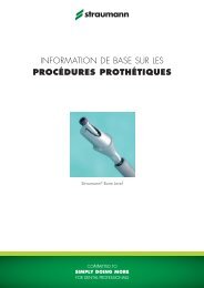
INSTRUCTIONS FOR THE DENTIST<br />
synOcta ® impression procedure, „<strong>Screw</strong>-<strong>retained</strong>“ and „Snap-on“<br />
<strong>Screw</strong>-<strong>retained</strong><br />
(Open tray)<br />
Snap-on<br />
(Closed tray)<br />
“click”<br />
1. Attach synOcta ® Impression caps<br />
to implants. Hand-tighten screws.<br />
2. Take the impression with a special<br />
tray with perforations for screws<br />
and elastomer impression matieral<br />
(vinyl polysiloxane or polyether<br />
rubber).<br />
1. Attach impression caps to the<br />
implants. The cap has engaged<br />
when a “click” is heard. If the<br />
cap is correctly seated, it can be<br />
turned on the implant.<br />
2. The octagon of the synOcta ®<br />
Positioning cylinder must be<br />
aligned with the octagon of the<br />
implant and inserted into the<br />
impression cap up to the limit stop.<br />
3. Undo the screws and remove the<br />
impression.<br />
4. Sending the impression to the<br />
dental lab.<br />
3. Take the impression with elastomer<br />
impression materials (vinyl<br />
polysiloxane or polyether rubber).<br />
4. Sending the impression to the<br />
dental lab.<br />
5. <strong>Screw</strong> the synOcta ® Analog to the<br />
impression caps hand-tight.<br />
5. Replace synOcta ® Analogs into<br />
the impression. The shoulder must<br />
engage audibly.<br />
Make the working model from special<br />
hard plaster, Type 4 (DIN 13911).<br />
Note: The impression-taking method is identical for implant shoulder Ø 4.8 mm RN and implant shoulder Ø 6.5 mm WN.
Art. No. Article Dimensions Material<br />
Components for synOcta ® impressions<br />
048.017V4 RN impression cap, snap-on height 8 mm plastic<br />
048.070V4 RN synOcta ® positioning cylinder, red, snap-on height 12 mm plastic<br />
048.010 RN synOcta ® impression cap, screw-<strong>retained</strong>, red, with integral<br />
guide screw<br />
height 10.1 mm<br />
anodized<br />
aluminium/titanium<br />
048.090 RN synOcta ® impression cap, built-in handle, red, with integral<br />
guide screw<br />
height 21 mm<br />
anodized<br />
aluminium/titanium<br />
048.013 WN impression cap, snap-on height 8 mm plastic<br />
048.095 WN synOcta ® positioning cylinder, white, snap-on height 12 mm plastic<br />
048.091 WN synOcta ® impression cap, screw-<strong>retained</strong>,<br />
with integral guide screw<br />
height 10 mm<br />
aluminium/titanium<br />
synOcta ® Master cast fabrication<br />
048.124 RN synOcta ® analog, gray (with red stripe) length 12 mm stainless steel<br />
048.171 WN synOcta analog, gray length 12 mm stainless steel<br />
Prosthetic Instruments<br />
046.400 SCS <strong>Screw</strong>driver, extra short length 15 mm stainless steel<br />
046.401 SCS <strong>Screw</strong>driver, short length 21 mm stainless steel<br />
046.402 SCS <strong>Screw</strong>driver, long length 27 mm stainless steel<br />
046.410 SCS <strong>Screw</strong>driver, extra short, for handpiece adapter length 20 mm stainless steel<br />
046.411 SCS <strong>Screw</strong>driver, short, for handpiece adapter length 26 mm stainless steel<br />
046.412 SCS <strong>Screw</strong>driver, long, for handpiece adapter length 32 mm stainless steel<br />
Caution: The plastic parts are intended for single use only. They must not be sterilized.<br />
To avoid damage (loss of elasticity, embrittlement) to the plastic parts, they must be protected<br />
from exposure to strong light or heat.<br />
For detailed information, refer to our brochure “Crown and Bridge Restorations with the<br />
synOcta ® Prosthetic System”, Art. No. 152.255.<br />
RN = Regular Neck<br />
WN = Wide Neck<br />
01/08 152.259/e
INSTRUCTIONS FOR THE DENTIST<br />
RN and WN synOcta ® 1.5 <strong>Screw</strong>-<strong>retained</strong> abutments<br />
Placement of two RN synOcta ® 1.5 <strong>Screw</strong>-<strong>retained</strong> abutments<br />
After fabrication, the restoration is given to the dentist on the master cast together with the abutments.<br />
Note: The method of placing the RN and WN synOcta ® 1.5 <strong>Screw</strong>-<strong>retained</strong> abutments is identical.<br />
1. Remove the superstructure and the<br />
abutments from the master cast with<br />
an SCS screwdriver.<br />
2. Insert the abutments into the implants<br />
and tighten the basal screws to a torque<br />
of 35 Ncm.<br />
3. Two methods for screw retention of the<br />
superstructure:<br />
A. <strong>Screw</strong> retention with SCS occlusal<br />
screw (Art. No. 048.350).<br />
In this method, the screw head is<br />
covered with some wax or guttapercha<br />
and subsequently the<br />
transocclusal screw channel is<br />
sealed off (e.g. with composite).<br />
Tightening torque = 15 Ncm!<br />
B. <strong>Screw</strong> retention with SCS guide<br />
screw (Art. No. 048.360/361/<br />
362/363/364).<br />
In this method, the SCS guide screw<br />
is shortened in the mouth to the level<br />
of the occlusal plane.<br />
Tightening torque = 15 Ncm!
Important: For tightening the basal screw, the ratchet<br />
(Art. No. 046.119) with attached torque control device<br />
(Art. No. 046.049) and an SCS screwdriver<br />
(Art. No. 046.400/401/402) are required.<br />
Important: The abutment must be positioned in the octagon before the screw<br />
is tightened. The basal screw in the synOcta ® 1.5 <strong>Screw</strong>-<strong>retained</strong> abutment<br />
is tightened to a torque of 35 Ncm.<br />
The SCS occlusal and guide screws are tightened to a torque of 15 Ncm.<br />
Art. No. Article Dimensions Material<br />
SCS occlusal and guide screws (according to the type of restoration)<br />
048.350<br />
048.350V4<br />
SCS Occlusal screw length 4.4 mm titanium<br />
048.360V4 Guide screw for RN synOcta ® coping bar,<br />
cannot be shortened<br />
length 6 mm<br />
titanium<br />
048.361V4 Guide screw for RN synOcta ® coping bar,<br />
can be shortened by 1.6 mm<br />
length 6 mm<br />
titanium<br />
048.362V4 SCS Guide screw for milling cylinder,<br />
cannot be shortened<br />
length 8 mm<br />
titanium<br />
048.363V4<br />
Guide screw for milling cylinder,<br />
can be shortened by 2 mm<br />
length 8 mm<br />
titanium<br />
048.364V4<br />
Guide screw, can be shortened<br />
by 2 mm<br />
length 10 mm<br />
titanium<br />
Prosthetic instruments<br />
SCS screwdriver (extra short 046.400, short 046.401, long 046.402)<br />
Ratchet, incl. service instrument 046.119<br />
Torque control device for ratchet 046.049<br />
Holding key 046.064<br />
For detailed information, refer to our brochure “Crown and Bridge Restorations with<br />
the synOcta ® Prosthetic System”, Art. No. 152.255.<br />
RN = Regular Neck<br />
WN = Wide Neck<br />
01/08 152.259/e
INSTRUCTIONS FOR THE DENTIST<br />
RN and WN synOcta ® gold abutment<br />
RN and WN synOcta ® gold abutment – placement of the final restoration<br />
Note<br />
The method of placing the RN and WN synOcta ® gold abutment is identical.<br />
1. Align the octagon of the customized<br />
gold abutment on the octagon of<br />
the implant and insert the mesostructure<br />
into the implant. Tighten the<br />
basal screw with a force of 35 Ncm.<br />
2. Then seal off the screw channel with<br />
gutta-percha, and finally cement the<br />
crown onto the mesostructure.
Important: For tightening the basal screw, the ratchet<br />
(Art. No. 046.119) with attached torque control device<br />
(Art. No. 046.049) and an SCS screwdriver<br />
(Art. No. 046.400/401/402) are required<br />
Important: The abutment must be positioned in the octagon before<br />
the screw is tightened. The basal screw in the RN and WN synOcta ®<br />
gold abutment is tightened to a torque of 35 Ncm.<br />
Prosthetic instruments<br />
SCS screwdriver (extra short 046.400, short 046.401, long 046.402)<br />
Ratchet, incl. service instrument 046.119<br />
Torque control device for ratchet 046.049<br />
Holding key 046.064<br />
For detailed information, refer to our brochure “Crown and Bridge Restorations with the<br />
synOcta ® Prosthetic System”, Art. No.152.255.<br />
RN = Regular Neck<br />
WN = Wide Neck<br />
01/08 152.259/e
INSTRUCTIONS FOR THE DENTIST<br />
RN and WN synOcta ® Cement <strong>retained</strong><br />
Placement of two RN synOcta ® Cement <strong>retained</strong> abutments in implants<br />
After fabrication, the restoration is given to the dentist on the master cast together with the abutments.<br />
Note<br />
The method of placing the RN and WN synOcta ® cement-<strong>retained</strong> abutments is identical.<br />
1. Undo the basal screws with the SCS<br />
screwdriver and transfer the index, with<br />
the abutments, from the master cast to<br />
the implants.<br />
2. Tighten the basal screws to a torque of<br />
35 Ncm.<br />
Note: In order to be able to release<br />
the basal screws again if required, fill<br />
the screw head and the abutment with<br />
gutta-percha.<br />
Then cement the superstructure<br />
permanently.
Important: For tightening the basal screw, the ratchet<br />
(Art. No. 046.119) with attached torque control device<br />
(Art. No. 046.049) and an SCS screwdriver<br />
(Art. No. 046.400/401/402) are required.<br />
Important: The abutment must be positioned in the octagon before<br />
the screw is tightened. Tighten the basal screw in the synOcta ®<br />
Cement <strong>retained</strong> abutment to a torque of 35 Ncm.<br />
Art. No. Article Dimensions Material<br />
Transfer of the synOcta ® Cement <strong>retained</strong> abutments<br />
048.059V4 Transfer aid for 048.605, RN height 6.5 mm plastic<br />
048.054V4 Transfer aid for 048.606, WN height 6.5 mm plastic<br />
Prosthetic instruments<br />
SCS screwdriver (extra short 046.400, short 046.401, long 046.402)<br />
Ratchet, incl. service instrument 046.119<br />
Torque control device for ratchet 046.049<br />
Holding key 046.064<br />
Caution: The plastic parts are intended for single use only. They must not be sterilized.<br />
To avoid damage (loss of elasticity, embrittlement) to the plastic parts, they must be protected<br />
from exposure to strong light or heat.<br />
For detailed information, refer to our brochure “Crown and Bridge Restorations with the<br />
synOcta ® Prosthetic System”, Art. No. 152.255.<br />
RN = Regular Neck<br />
WN = Wide Neck<br />
01/08 152.259/e
INSTRUCTIONS FOR THE DENTIST<br />
RN and WN synOcta ® Angled<br />
Placement of an RN synOcta ® Angled abutment into the implant<br />
After fabrication, the restoration is given to the dentist on the master cast together with the abutments.<br />
1. Undo the basal screw with the SCS screwdriver and remove the<br />
abutment with index from the master cast.<br />
2. Insert the abutment into the<br />
implant and tighten the basal<br />
screw to a torque of 35 Ncm.<br />
3. Undo the occlusal screw<br />
and remove the index. Then<br />
cement or screw in the<br />
restoration.<br />
Note: If the restoration is cemented, the lateral and occlusal opening must be sealed off with gutta-percha.<br />
Placement of a WN synOcta ® Angled abutment into the implant<br />
1. Undo the basal screw with the SCS screwdriver and remove the<br />
abutment with index from the master cast.<br />
2. Insert the abutment into the<br />
implant and tighten the basal<br />
screw to a torque of 35 Ncm.<br />
3. Remove the index, then<br />
cement the restoration.<br />
Note: Before cementing the restoration, the lateral opening must be sealed off with gutta-percha.
Important: For tightening the basal screw, the ratchet<br />
(Art. No. 046.119) with attached torque control device<br />
(Art. No. 046.049) and an SCS screwdriver<br />
(Art. No. 046.400/401/402) are required.<br />
Important: The abutment must be positioned in the octagon before the screw<br />
is tightened. The basal screw in the RN and WN synOcta ® Angled abutment<br />
is tightened to a torque of 35 Ncm.<br />
Important: If a screw-<strong>retained</strong> restoration is used, the SCS occlusal screw must<br />
be tightened to a torque of 15 Ncm.<br />
Art. No. Article Dimensions Material<br />
Transfer of the RN and WN synOcta ® Angled abutments<br />
048.000V4 Transfer aid for RN synOcta ® Angled, short, 15° and 20° height 4 mm plastic<br />
048.002V4 Transfer aid for RN synOcta ® Angled, long, 15° and 20° height 4 mm plastic<br />
048.032 Transfer aid for WN synOcta ® Angled, 15° height 5 mm plastic<br />
048.350<br />
048.350V4<br />
SCS occlusal screw length 4.4 mm titanium<br />
Prosthetic instruments<br />
SCS screwdriver (extra short 046.400, short 046.401, long 046.402)<br />
Ratchet, incl. service instrument 046.119<br />
Torque control device for ratchet 046.049<br />
Holding key 046.064<br />
Caution: The plastic parts are intended for single use only. They must not be sterilized. To avoid damage (loss of<br />
elasticity, embrittlement) to the plastic parts, they must be protected from exposure to strong light or heat.<br />
For detailed information, refer to our brochure “Crown and Bridge Restorations with the synOcta ® Prosthetic System”,<br />
Art. No.152.255.<br />
RN = Regular Neck<br />
WN = Wide Neck<br />
01/08 152.259/e
INSTRUCTIONS FOR THE DENTIST<br />
RN synOcta ® Transversal<br />
Placement of an RN synOcta ® Transversal (TS) abutment into the implant<br />
After fabrication, the restoration is given to the dentist on the master<br />
cast together with the abutments.<br />
1. Undo the basal screw with the SCS<br />
screwdriver and remove the index from<br />
the master cast.<br />
2. Insert the abutment into the implant<br />
and tighten the basal screw to a torque<br />
of 35 Ncm.<br />
Then incorporate the superstructure.<br />
3. Attach the restoration with the transversal<br />
screw, and carefully hand-tighten the<br />
transversal screw with the TS hexagonal<br />
screwdriver.
Important: For tightening the basal screw, the ratchet<br />
(Art. No. 046.119) with attached torque control device<br />
(Art. No. 046.049) and an SCS screwdriver<br />
(Art. No. 046.400/401/402) are required.<br />
Important: The abutment must be positioned in the octagon before the screw<br />
is tightened. Tighten the basal screw in the RN synOcta ® Transversal (TS)<br />
abutment to a torque of 35 Ncm.<br />
Important: The transversal screw must only be hand-tightened with the TS<br />
screwdriver (Art. No. 046.420).<br />
Art. No. Article Dimensions Material<br />
Transfer of the RN synOcta ® Transversal (TS) abutment<br />
048.003V4 Transfer aid for RN synOcta ® TS abutment height 5 mm plastic<br />
Prosthetic instruments<br />
SCS screwdriver (extra short 046.400, short 046.401, long 046.402)<br />
Ratchet, incl. service instrument 046.119<br />
Torque control device for ratchet 046.049<br />
Holding key 046.064<br />
TS hexagonal screwdriver 046.420<br />
Caution: The plastic parts are intended for single use only. They must not be sterilized.<br />
To avoid damage (loss of elasticity, embrittlement) to the plastic parts, they must be protected<br />
from exposure to strong light or heat.<br />
For detailed information, refer to our brochure “Crown and Bridge Restorations with<br />
the synOcta ® Prosthetic System”, Art. No. 152.255.<br />
RN = Regular Neck<br />
01/08 152.259/e
INSTRUCTIONS FOR THE DENTIST<br />
<strong>Screw</strong>ing in an RN solid abutment with subsequent impression taking and temporary restoration<br />
<strong>Screw</strong>ing in the abutment<br />
1. Insert the RN solid abutment into<br />
the driver and screw it into the<br />
implant.<br />
Note: WN solid abutments must<br />
be screwed into the WN implant<br />
using the SCS screwdriver.<br />
2. Position the ratchet with attached<br />
torque control device and stabilize<br />
with the holding key.<br />
3. Tighten the abutment with a force of<br />
35 Ncm and remove the instruments<br />
again.<br />
Taking the impression<br />
1. Attach impression cap to implant<br />
(make sure it “clicks” into place).<br />
If it is correctly seated, the<br />
impression cap is easy to turn on<br />
the implant.<br />
2. Insert the positioning cylinder into<br />
the impression cap. Check that it is<br />
seated without any gap.<br />
3. Take the impression with elastomer<br />
impression material (vinyl<br />
polysiloxane or polyether rubber).<br />
Impression, e.g. for RN (gray,<br />
height 5.5 mm) and WN (green,<br />
height 4.0 mm) following removal<br />
from the mouth.<br />
Temporary restoration<br />
Option A: Temporary restoration with<br />
temporary copings (plastic).<br />
Temporary copings can be individually<br />
shortened and coated with plastic<br />
on the master cast or intraorally by the<br />
conventional technique.<br />
Option B: Temporary restoration with<br />
protective caps (PEEK).<br />
Protective caps are cemented on solid<br />
abutments with temporary cement.<br />
Note: The method of impression taking and the temporary restoration are identical for RN and WN solid abutments.
Art. no. Article Dimensions Material<br />
RN and WN solid abutments<br />
048.540 RN Solid abutment, 6°, yellow height 4 mm titanium<br />
048.541 RN Solid abutment, 6°, gray height 5.5 mm titanium<br />
048.542 RN Solid abutment, 6°, blue height 7 mm titanium<br />
048.545 WN Solid abutment, 6°, green height 4 mm titanium<br />
048.546 WN Solid abutment, 6°, brown height 5.5 mm titanium<br />
Color-coded components for RN and WN impressions<br />
048.017V4 RN impression cap height 8 mm plastic<br />
048.060V4 Positioning cylinder for 048.540, yellow height 10.2 mm plastic<br />
048.061V4 Positioning cylinder for 048.541, gray height 10.2 mm plastic<br />
048.062V4 Positioning cylinder for 048.542, blue height 10.2 mm plastic<br />
048.013V4 WN Impression cap height 8 mm plastic<br />
048.065V4 Positioning cylinder for 048.545, green height 10 mm plastic<br />
048.066V4 Positioning cylinder for 048.546, brown height 10 mm plastic<br />
Components for RN and WN temporary restorations<br />
048.654 RN Temporary coping for RN solid abutments, bridge height 8.5 mm plastic<br />
048.655 RN Temporary coping for RN solid abutments, crown height 8.5 mm plastic<br />
048.047V4 RN Protective cap, cemented, for 048.540 height 5.8 mm PEEK<br />
048.048V4 RN Protective cap, cemented, for 048.541 height 7.3 mm PEEK<br />
048.049V4 RN Protective cap, cemented, for 048.542 height 8.8 mm PEEK<br />
048.656 WN Temporary coping for WN solid abutments, bridge height 7.3 mm plastic<br />
048.657 WN Temporary coping for WN solid abutments, crown height 7.3 mm plastic<br />
048.051 WN Protective cap, cemented, for 048.545 height 6 mm PEEK<br />
048.052 WN Protective cap, cemented, for 048.546 height 7.5 mm PEEK<br />
Caution: The plastic parts are intended for single use only.<br />
They must not be sterilized. To avoid damage (loss of elasticity, embrittlement) to the plastic parts,<br />
they must be protected from exposure to strong light or heat.<br />
Inserting instruments for RN and WN Solid abutments<br />
For RN Solid abutments: solid abutment driver (short, 046.067; long, 046.068)<br />
For WN Solid abutments: SCS screwdriver (extra short 046.400, short 046.401, long 046.402<br />
Ratchet 046.119<br />
Torque control device 046.049<br />
Holding key 046.064<br />
For detailed information, refer to our brochures “Fixed Crown and Bridge Restorations with the solid abutment system”,<br />
Art. No. 152.254.<br />
RN = Regular Neck<br />
WN = Wide Neck<br />
01/08 152.259/e
INSTRUCTIONS FOR THE DENTal Technician<br />
Fabrication of a mesostructure with the RN synOcta ®<br />
gold abutment and a cement-<strong>retained</strong> crown<br />
Fabrication of the mesostructure<br />
1. In order to design the emergence<br />
profile optimally on the neck of the<br />
crown, a gingival mask should be<br />
made on the master cast.<br />
2. Attach the RN synOcta ® gold<br />
abutment to the analog, ensuring<br />
that the abutment is aligned in the<br />
octagon of the analog. Then handtighten<br />
the screw with an SCS<br />
screwdriver.<br />
3. If required, the modeling aid can<br />
be shortened occlusally to suit the<br />
anatomical conditions.<br />
4. Make a wax model of the mesostructure<br />
on the abutment. Minimum<br />
wax thickness 0.7 mm.<br />
5. Check for correct spacing with the<br />
silicone index from the wax-up.<br />
6. For reasons of hygiene, the<br />
mesostructure/crown cement gap<br />
must not be more than 2.0 mm<br />
below the gingiva.<br />
7. Embed the mesostructure.<br />
Do not use a wetting agent!<br />
To prevent the cast-on alloy overflowing,<br />
it is essential to clean the<br />
slender edge of the coping and the<br />
internal configuration thoroughly<br />
with alcohol.<br />
8. Cast the mesostructure in the conventional<br />
way. Do not use speed<br />
investment materials! Follow the<br />
instructions for use provided by<br />
the manufacturer of the investment<br />
material and cast-on alloy!<br />
9. Carefully devest the casting<br />
using only ultrasound, water jet<br />
or pickling. Do not sandblast!<br />
10. Finish the mesostructure. Polish the<br />
subgingival part.
Fabrication of the cement-<strong>retained</strong> crown<br />
11. Block out the screw channel and<br />
model the crown.<br />
12. Invest, cast and veneer the crown<br />
in the conventional way.<br />
13. a The mesostructure with the<br />
finished crown.<br />
13. b <br />
Art. No. Article Dimensions Material<br />
RN synOcta ® gold abutment for transocclusal screw-<strong>retained</strong> or cement-<strong>retained</strong> crowns<br />
048.642 RN synOcta ® gold abutment for<br />
premounted modeling aid (including<br />
screw*)<br />
height 14.1 mm<br />
Ceramicor/burn-out<br />
plastic/titanium<br />
*also available as spare part Art. No. 048.356<br />
For detailed information, refer to our brochure “Crown and Bridge Restorations with the synOcta ®<br />
Prosthetic System”, Art. No. 152.255.<br />
RN = Regular Neck<br />
01/08 152.259/e