Chip Blaster manual - Salvex
Chip Blaster manual - Salvex
Chip Blaster manual - Salvex

You also want an ePaper? Increase the reach of your titles
YUMPU automatically turns print PDFs into web optimized ePapers that Google loves.
.<br />
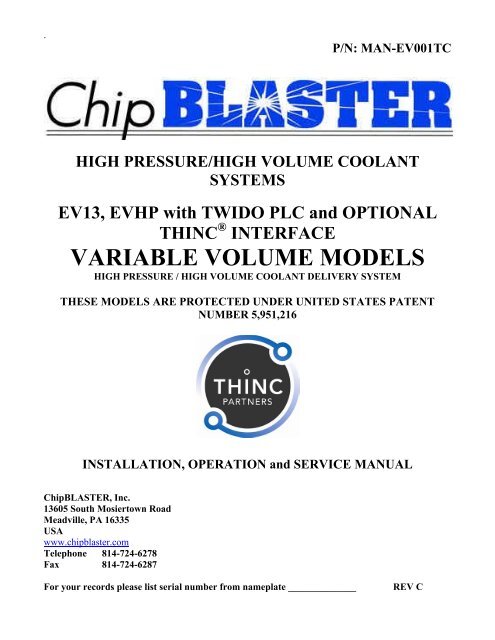
P/N: MAN-EV001TC<br />
HIGH PRESSURE/HIGH VOLUME COOLANT<br />
SYSTEMS<br />
EV13, EVHP with TWIDO PLC and OPTIONAL<br />
THINC ® INTERFACE<br />
VARIABLE VOLUME MODELS<br />
HIGH PRESSURE / HIGH VOLUME COOLANT DELIVERY SYSTEM<br />
THESE MODELS ARE PROTECTED UNDER UNITED STATES PATENT<br />
NUMBER 5,951,216<br />
INSTALLATION, OPERATION and SERVICE MANUAL<br />
<strong>Chip</strong>BLASTER, Inc.<br />
13605 South Mosiertown Road<br />
Meadville, PA 16335<br />
USA<br />
www.chipblaster.com<br />
Telephone 814-724-6278<br />
Fax 814-724-6287<br />
For your records please list serial number from nameplate ______________<br />
REV C
<strong>Chip</strong>BLASTER, Inc. 2<br />
REVISION RECORD<br />
REVISION DATE PERSON DESCRIPTION OF CHANGE<br />
A 17MAR08 TD NEW RELEASE<br />
B 02APR 08 TD UPDATE PRINTS<br />
C 16 OCT 08 TD UPDATE EXPLANATION OF<br />
MARKINGS
<strong>Chip</strong>BLASTER, Inc. 3<br />
GENERAL:<br />
This <strong>manual</strong> covers the following <strong>Chip</strong>BLASTER models:<br />
EV13 and EVHP with THINC ® Control<br />
For the model number of your unit refer to the data nameplate located on<br />
the enclosure door.<br />
UNIT MODEL NUMBER<br />
UNIT SERIAL NUMBER<br />
DATA NAME PLATE
<strong>Chip</strong>BLASTER, Inc. 4<br />
1.0. GENERAL WARNINGS:<br />
Thank you for purchasing a <strong>Chip</strong>BLASTER high-pressure coolant system.<br />
For reliable, safe and long term operation of your <strong>Chip</strong>BLASTER:<br />
Machine must be installed and connected to electric service per the installation<br />
portion of this <strong>manual</strong>.<br />
All persons who will be operating and maintaining this machine must read and<br />
understand this <strong>manual</strong>.<br />
DO NOT AT ANY TIME USE FLAMMABLE OR EXPLOSIVE FLUIDS IN OR<br />
NEAR MACHINE.<br />
THE ADJUSTABLE FREQUENCY DRIVE HAS THE POTENTIAL TO HOLD A<br />
LETHAL CHARGE FOR APPROXIMATELY 10 MINUTES AFTER POWER IS<br />
REMOVED FROM THE DRIVE. REFER TO THE DRIVE MANUAL FOR<br />
DETAILS.<br />
DO NOT STAND ON MOTORS, SUPPORTS, or JUNCTION BOXES WHILE<br />
WORKING ON THE <strong>Chip</strong>BLASTER.<br />
REFER TO SECTION 4.1. FOR EXPLANATION OF MARKINGS<br />
1.0
<strong>Chip</strong>BLASTER, Inc. 5<br />
2.0. TABLE OF CONTENTS:<br />
General Page 3<br />
General warnings Section 1.0 Page 4<br />
Table of contents Section 2.0 Page 5<br />
Specifications Section 3.0 Page 9<br />
Safety precautions Section 4.0 Page 11<br />
Explanation of markings Section 4.1 Page 11<br />
Storage Section 5.0 Page 16<br />
Moving machine Section 6.0 Page 16<br />
Placing a <strong>Chip</strong>BLASTER Section 7.0 Page 17<br />
Mechanical installation Section 8.0 Page 19<br />
Electrical installation Section 9.0 Page 19<br />
Control interface Section 9.1 Page 20<br />
Power connections Section 9.3 Page 20<br />
Start up Section 10.0 Page 20<br />
System air purge Section 11.0 Page 21<br />
Single filter Section 11.1 Page 21<br />
Dual filter Section 11.2 Page 21<br />
Autocross Section 11.3 Page 22<br />
Operation Section 12.0 Page 23<br />
Electrical operation Section 12.1 Page 23<br />
Coolant flow Section 12.2 Page 23<br />
Theory of operation auto cross option Section 12.3 Page 26<br />
Alarms Section 13.0 Page 27<br />
Preventive maintenance Section 14.0 Page 28<br />
Maintenance schedule chart Section 14.1 Page 28<br />
High pressure pump check oil Section 14.2 Page 29<br />
High pressure pump change oil Section 14.3 Page 30<br />
High pressure pump check belt Section 14.4 Page 33<br />
High pressure pump check for leaks Section 14.5 Page 33<br />
High pressure pump rebuild Section 14.6 Page 33<br />
Filter pump - check for leaks Section 14.9 Page 33<br />
Bag filter unit - check pressure gauges Section 14.12 Page 33<br />
Bag filter unit - change filter<br />
single filter unit Section 14.13.1 Page 34<br />
Bag filter unit – change filter<br />
dual filter-unit shut down Section 14.14 Page 35<br />
2.0
<strong>Chip</strong>BLASTER, Inc. 6<br />
2.0. TABLE OF CONTENTS (Cont.):<br />
Bag filter unit - dual filter unit operating Section 14.15 Page 36<br />
Bag filter unit – autocross unit operating Section 14.16 Page 37<br />
Filter replacement form Section 14.16.13 Page 38<br />
Bag filter unit change filter check for leaks Section 14.17 Page 39<br />
Post filter - changing Section 14.18 Page 39<br />
Sock filter - changing Section 14.19 Page 39<br />
Float switch – cleaning Section 14.23 Page 39<br />
Tank - cleaning Section 14.25 Page 40<br />
Pump mounting bolts – checking Section 14.27 Page 40<br />
Return (transfer) pump – check flow rate Section 14.29 Page 40<br />
Return (transfer) pump – check for leaks Section 14.30 Page 40<br />
Return (transfer) pump – check inlet/outlet Section 14.31 Page 40<br />
LDENS sample line filter - changing Section 14.34 Page 41<br />
Equipment cooling fans – cleaning Section 14.37 Page 41<br />
Troubleshooting Section 15.0 Page 42<br />
Troubleshooting chart Section 15.1 Page 42<br />
Transducer voltage Section 15.2 Page 44<br />
Troubleshooting flow chart Section 15.3 Page 45<br />
Drive error codes – ALTIVAR 31 Drive Section 15.4 Page 46<br />
Drive as set parameters 230 VAC Section 15.8 Page 50<br />
Drive as set parameters 460 VAC Section 15.9 Page 53<br />
Pressure adjustment procedure Section 16.0 Page 56<br />
High pressure pump replacement (single pump) Section 17.0 Page 59<br />
Belt installation Section 18.0 Page 61<br />
Align sprockets Section 18.1 Page 61<br />
Install belt Section 18.2 Page 61<br />
Belt tensioning – General method Section 18.3 Page 61<br />
Belt tensioning – Force deflection method Section 18.4 Page 62<br />
Deflection and force chart Section 18.5 Page 63<br />
System contamination purging procedure Section 19.0 Page 64<br />
Electrical drawings Section 20.0 Page 67<br />
Power wiring schematic Section 20.1 Page 67<br />
Control wiring schematic Section 20.3 Page 68<br />
PLC input wiring Section 20.5 Page 69<br />
PLC output wiring Section 20.7 Page 70<br />
Drive control and power wiring Section 20.9 Page 71<br />
Power and Mistblaster Interface Section 20.13 Page 72<br />
Interface Cable Wiring Section 20.15 Page 73<br />
2.0
<strong>Chip</strong>BLASTER, Inc. 7<br />
2.0. TABLE OF CONTENTS (Cont.):<br />
EV Sub panel layout Section 20.23 Page 74<br />
Schematic piping drawings Section 21.0 Page 75<br />
EV Piping schematic single filter Section 21.1 Page 75<br />
EV Piping schematic dual filters Section 21.2 Page 76<br />
EV Piping schematic autocross filters Section 21.3 Page 77<br />
Mechanical assembly Section 22.0 Page 78<br />
EV Gauge panel side Section 22.1 Page 78<br />
EV Filter side Section 22.6 Page 79<br />
EV Control panel side Section 22.11 Page 80<br />
EV Filter assembly Section 22.16 Page 81<br />
EV Manifold block Section 22.17 Page 82<br />
EV Sub plate plan view Section 22.22 Page 83<br />
EV Oil level site gauge Section 22.27 Page 84<br />
EV Tank plan view<br />
w/ screens and baffles Section 22.28 Page 85<br />
EV Ship loose items Section 22.33 Page 86<br />
EV Spare parts Section 22.38 Page 87<br />
Footprint drawings Section 23.0 Page 88<br />
EV Footprint Section 23.1 Page 88<br />
Warranty Section 24.0 Page 89<br />
Warranty (limited) – New equipment Section 24.1 Page 89<br />
Warranty (limited) – Used equipment Section 24.2 Page 91<br />
Warranty (limited) – Retrofits Section 24.3 Page 93<br />
Warranty claim form Section 24.4 Page 95<br />
Warranty registration card Section 24.5 Page 96<br />
Warranty validation card Section 24.6 Page 97<br />
Optional Equipment Section 27.0 Page 98<br />
Magelis Human machine interface unit Section 27.1 Page 98<br />
Oil skimmer for model<br />
without MistBLASTER Section 27.15 Page 101<br />
Magnetic separator Section 27.17 Page 103<br />
Hydrocyclonic filter insert Section 27.18 Page 104<br />
Multiple preset pressures Section 27.19 Page 105<br />
Low pressure wash down option Section 27.20 Page 106<br />
Optional drop in chiller Section 27.21 Page 107<br />
2.0
<strong>Chip</strong>BLASTER, Inc. 8<br />
2.0. TABLE OF CONTENTS (Cont.):<br />
Supplement Data Section 28.0 Page 118<br />
Program revision using EEPROM chip Section 28.1 Page 118<br />
1000 PSI orifice chart Section 28.2 Page 119<br />
1500 PSI orifice chart Section 28.3 Page 120<br />
2000 PSI orifice chart Section 28.4 Page 121<br />
2500 PSI orifice chart Section 28.5 Page 122<br />
3000 PSI orifice chart Section 28.6 Page 123<br />
5000 PSI orifice chart Section 28.7 Page 123<br />
2.0
<strong>Chip</strong>BLASTER, Inc. 9<br />
3.0. EV13, EVHP SPECIFICATIONS:<br />
3.0
<strong>Chip</strong>BLASTER, Inc. 10<br />
3.0. SPECIFICATIONS: (Cont.):<br />
FCC REGULATIONS:<br />
THIS DEVICE COMPLIES WITH PART 15 OF THE FCC RULES. OPERATION IS<br />
SUBJECT TO THE FOLLOWING TWO CONDITIONS: (1) THIS DEVICE MAY NOT CAUSE<br />
HARMFUL INTERFERENCE, AND (2) THIS DEVICE MUST ACCEPT ANY<br />
INTERFERENCE RECEIVED, INCLUDING INTERFERENCE THAT MAY CAUSE<br />
UNDESIRED OPERATION.<br />
**ALL SPECIFICATIONS, INSTRUCTION, PICTURES, AND ILLUSTRATIONS IN THIS<br />
MANUAL ARE BELIEVED TO BE ACCURATE AND MAY CONTAIN CHIPBLASTER INC.<br />
PROPRIETARY INFORMATION, WHICH IS PRIVILEGED, CONFIDENTIAL, OR<br />
SUBJECT TO COPYRIGHT / PATENT BELONGING TO CHIPBLASTER INC. THIS<br />
MANUAL IS INTENDED FOR THE OPERATION AND MAINTENANCE OF YOUR<br />
CHIPBLASTER UNIT. YOU ARE HEREBY NOTIFIED THAT ANY DISSEMINATION,<br />
DISTRIBUTION, COPYING, OR ACTION TAKEN IN REGARD TO THE CONTENT OF<br />
THIS MANUAL IS STRICTLY PROHIBITED AND MAY BE UNLAWFUL. CHIPBLASTER<br />
INC. ALSO RESERVES THE RIGHT TO CHANGE THE CONTENTS OF THIS MANUAL<br />
WITHOUT NOTICE. IF YOU HAVE ANY QUESTIONS PLEASE CONTACT CHIPBLASTER<br />
INC. AT (814) 724-6278.<br />
3.0
<strong>Chip</strong>BLASTER, Inc. 11<br />
4.0. SAFETY PRECAUTIONS:<br />
The items described in these instructions are a very important, so that you can use<br />
the <strong>Chip</strong>BLASTER safely, prevent injury to yourself and other people around you as well<br />
as prevent damage to property in the area. Thoroughly familiarize yourself with the<br />
symbols and indications shown below and then continue to read the <strong>manual</strong>. Make sure<br />
that you observe all warnings given.<br />
4.1. EXPLANATION of MARKINGS:<br />
Symbols<br />
Meaning of Symbols<br />
!<br />
DANGER<br />
Indicates that error in operation may lead to death or serious injury.<br />
WARNING<br />
Indicates that error in operation may lead to injury (*1) to people or that<br />
these errors may cause damage to physical property. (*2)<br />
*(1) Such things as injury, burns or shock that will require<br />
hospitalization or long periods of outpatient treatment.<br />
*(2) Physical property damage refers to wide-ranging damage to<br />
assets and materials.<br />
PROHIBITED<br />
Indicates prohibition (Don’t do it).<br />
What is prohibited will be described in or near the symbol in either text<br />
or picture form.<br />
4.0 - 4.1
<strong>Chip</strong>BLASTER, Inc. 12<br />
4.1. EXPLANATION of MARKINGS (Cont.):<br />
Symbols (Cont.)<br />
Meaning of Symbols<br />
!<br />
MANDATORY<br />
Indicates something mandatory (must be done).<br />
What is mandatory will be described in or near the symbol in either text or<br />
picture form.<br />
PINCH POINT<br />
Any point where fingers may be pinched by lids or covers.<br />
Exercise caution when closing lids or covers. (Oil skimmer cover).<br />
CUTTING HAZARD<br />
Any point where exposed fan blades may cause a cutting hazard to fingers<br />
when guard or inlet hose is not in place. Do not operate without guard or<br />
inlet hose in place. (Inlet to MistBLASTER).<br />
PINCH POINT<br />
Any point where fingers may be pinched by the motion of a belt.<br />
Do not operate with guard or cover open. (Oil skimmer).<br />
LIFTING HAZARD<br />
Use caution when lifting filter bags from filter housing. Bags may be<br />
heavy depending on the material being machined.<br />
4.1
<strong>Chip</strong>BLASTER, Inc. 13<br />
4.1. EXPLANATION of MARKINGS (Cont.):<br />
Symbols<br />
Meaning of Symbols<br />
ELECTRICAL SHOCK HAZARD<br />
Shut off main disconnect before opening any electrical enclosures or<br />
junction boxes. UNITS WITH ADJUSTABLE FREQUENCY<br />
DRIVES: BEFORE PERFORMING ANY WORK, BE AWARE<br />
THAT A DRIVE WILL HOLD A LETHAL CHARGE FOR A<br />
MINIMUM OF 10 MINUTES.<br />
LOCK OUT ELECTRICAL POWER<br />
Lock out and tag any and all disconnect switches before performing any<br />
maintenance work on equipment.<br />
SAFETY GLASSES REQUIRED<br />
When removing filter bags or working on equipment, safety glasses must<br />
be worn to prevent injury from splashing fluid or from other hazards.<br />
MACHINE STARTS AUTOMATICALLY<br />
<strong>Chip</strong>BLASTER equipment will start without operator input. Do not<br />
remove any guards or covers until disconnect switches are shut off, locked<br />
out and tagged.<br />
UNPLUG SOURCE OF ENERGY<br />
Before performing any work on items, such as the oil skimmer, unplug the<br />
unit.<br />
4.1
<strong>Chip</strong>BLASTER, Inc. 14<br />
4.1. EXPLANATION of MARKINGS (Cont.):<br />
Symbols (Cont.)<br />
Meaning of Symbols (Cont.)<br />
NO ACCESS FOR UNAUTHORIZED PERSONS<br />
Do not open electrical enclosures or remove any guards if you have not<br />
been trained or do not have knowledge of the equipment.<br />
FORK TRUCK LIFTING POINT<br />
To transport equipment, forks of truck must be located between points<br />
indicated so that mechanical damage to machine will not result.<br />
SAFE OPERATING PRESSURE<br />
Safe operating pressure will be listed below symbol in PSIG and Bar.<br />
Do not operate above stated pressures as equipment damage or personal<br />
injury will result.<br />
DO NOT STEP OR STAND ON<br />
Do not use surface as a step or platform when servicing equipment.<br />
Motors and electrical boxes are not designed to be used as steps or<br />
platforms and injury may result from falls.<br />
READ THE TECHNICAL MANUAL<br />
Before attempting to work on or repair this machine read and understand<br />
this <strong>manual</strong>. If certain procedures are not followed, mechanical and or<br />
personal injury will result.<br />
4.1
<strong>Chip</strong>BLASTER, Inc. 15<br />
4.1. EXPLANATION of MARKINGS (Cont.):<br />
Symbols (Cont.)<br />
Meaning of Symbols (Cont.)<br />
WEAR SAFETY GLOVES<br />
When changing filter bags it is recommended to wear safety gloves to<br />
protect hands from metal chips and the coolant that may be used in the<br />
machine.<br />
DO NOT OPERATE WITH GUARD REMOVED<br />
Do not operate machine with guards removed as hazards to personnel will<br />
be present and injury to personnel could result.<br />
LIFTING POINT<br />
Machine must only be lifted at points indicated in order to avoid<br />
mechanical damage and personal injury. Lifting slings or chain slings<br />
must be adequately sized to carry the weight of the MistBLASTER.<br />
Refer to MistBLASTER footprint drawing for actual weight.<br />
BURN HAZARD HOT SURFACE<br />
Surface of transformer will become hot after extended periods of<br />
operation. Do not set anything on transformer or restrict airflow around<br />
transformer. DO NOT TOUCH.<br />
INHALATION HAZARD<br />
Consult MSDS Sheet for Hazard Listings<br />
Possible Coolant Mist Emission
<strong>Chip</strong>BLASTER, Inc. 16<br />
5.0. STORAGE:<br />
!<br />
4.1<br />
5.1. If the <strong>Chip</strong>BLASTER is to be stored for any period of time it must be keep in an area that is<br />
protected from freezing. Freezing temperatures will damage the pumps and the valves. Keep<br />
<strong>Chip</strong>BLASTER covered until ready to move to site. If MistBLASTER is also supplied keep<br />
covered.<br />
6.0. MOVING MACHINE:<br />
!<br />
6.1. When moving the <strong>Chip</strong>BLASTER to the final site the following must be adhered to:<br />
6.1.1. Lift <strong>Chip</strong>BLASTER only from the opposite end of the electrical enclosure.<br />
Forks must extend the full distance under <strong>Chip</strong>BLASTER.<br />
6.1.2. The fork truck lifting capacity must be sufficent to safely lift the <strong>Chip</strong>BLASTER<br />
without tipping. Refer to footprint drawing (Section 23) for machine dry weight.<br />
!<br />
MOVE SLOWLY AS NOT TO DROP THE <strong>Chip</strong>BLASTER.<br />
!<br />
DO NOT TRY TO MOVE <strong>Chip</strong>BLASTER WITH FLUID IN TANK.<br />
!<br />
DO NOT STAND UNDER <strong>Chip</strong>BLASTER AT ANY TIME.<br />
If MistBLASTER is supplied with <strong>Chip</strong>BLASTER:<br />
6.2. When lifting or moving the MistBLASTER, lift only at the eye bolts provided on the top.<br />
6.3. Sling must be of sufficent capacity to safely lift the MistBLASTER.<br />
!<br />
!<br />
DO NOT STAND UNDER MistBLASTER AT ANY TIME.<br />
DO NOT MOVE A <strong>Chip</strong>BLASTER WITH A MistBLASTER MOUNTED ON<br />
TOP.<br />
5.0 - 6.0
<strong>Chip</strong>BLASTER, Inc. 17<br />
7.0. PLACING A <strong>Chip</strong>BLASTER:<br />
7.1. After you receive your new <strong>Chip</strong>BLASTER unit the first thing you need to do is prepare<br />
the site where you would like to place the unit.<br />
!<br />
INSTALLATION SITE MUST BE FLAT AND LEVEL.<br />
7.1.1. You need to keep the unit within 10’ of the machining center that you are<br />
connecting the <strong>Chip</strong>BLASTER to.<br />
7.1.2. Locate the unit so the <strong>Chip</strong>BLASTER’s electrical cabinet is within 15’ of the<br />
machining center’s electrical cabinet.<br />
7.1.3. Make sure you place the unit so maintenance can easily get to the filter housing<br />
and electrical cabinet on the <strong>Chip</strong>BLASTER unit. Refer to footprint drawing<br />
(Section 23) for recommended clearances.<br />
7.2. After you have the site cleared for the <strong>Chip</strong>BLASTER unit you are ready to prepare the<br />
<strong>Chip</strong>BLASTER.<br />
7.2.1. Remove the lumber that is used to hold the unit in place during transporation using<br />
a phillips screw driver or an electric screw gun.<br />
7.2.2. Before you remove the <strong>Chip</strong>BLASTER from the skid take a moment and remove<br />
the lid from the top of the <strong>Chip</strong>BLASTER unit. Remove the bag containing the<br />
leveling feet.<br />
7.2.3. When removing the <strong>Chip</strong>BLASTER only from the opposite end of the electrical<br />
enclosure.<br />
7.2.4. Insure the forks extend completely under the <strong>Chip</strong>BLASTER unit to the support.<br />
!<br />
DO NOT AT ANY TIME REACH UNDER THE <strong>Chip</strong>BLASTER UNIT<br />
OR STAND UNDER THE <strong>Chip</strong>BLASTER UNIT WHILE IT IS<br />
SUPPORTED BY A FORK TRUCK. IF YOU MUST REACH UNDER<br />
THE MACHINE BLOCK IT UP FOR SAFETY.<br />
7.2.5. The EV units are shipped from the factory with leveling feet as shown in figure<br />
1a. The leveling feet must be installed when setting up the <strong>Chip</strong>BLASTER.<br />
7.2.8. After you remove the <strong>Chip</strong>BLASTER from the skid take the set of four feet<br />
and install the studs of the leveling feet through the holes in the legs. Block unit<br />
while installing feet for safety. Reference; top of foot to the bottom of second nut<br />
(1”). The feet have two functions the first being to level the <strong>Chip</strong>BLASTER unit<br />
and the second being to help eliminate the transfer of noise. Refer to figure 1.<br />
7.2.9. After you have the feet in place proceed with moving the <strong>Chip</strong>BLASTER<br />
into place.
<strong>Chip</strong>BLASTER, Inc. 18<br />
7.0. PLACING A <strong>Chip</strong>BLASTER (Cont.):<br />
Mounting feet installation<br />
Figure 1<br />
Recommended<br />
1 inch (25.4 mm)<br />
EV<br />
!<br />
Upon positioning the unit, go ahead and level the machine. The <strong>Chip</strong>BLASTER must be<br />
level to insure proper operation. Remember the <strong>Chip</strong>BLASTER unit has float switches<br />
and an overflow, if the unit is not level these items may not work properly.<br />
After <strong>Chip</strong>BLASTER is in place and level, remove all items from inside of the tank..<br />
Items located in the tank are: hoses, filter bag(s), and pre-filters. Place all hoses at the<br />
back of the unit (same end as filters).<br />
7.2.10. After you remove everything from inside the tank, you are now ready to either<br />
contact <strong>Chip</strong>BLASTER, Inc. to schedule installation or proceed yourself<br />
depending on your agreement.<br />
!<br />
POWER FOR <strong>Chip</strong>BLASTER MUST BE AVAILABLE BEFORE<br />
SCHEDULING INSTALLATION.<br />
7.0
<strong>Chip</strong>BLASTER, Inc. 19<br />
8.0. MECHANICAL INSTALLATION:<br />
8.1. PLUMBING INSTALLATION:<br />
8.1.1. When you are ready to start the installation of the <strong>Chip</strong>BLASTER unit you first<br />
must locate the high-pressure hoses that <strong>Chip</strong>BLASTER Inc. has provided.<br />
Connect the female end to the <strong>Chip</strong>BLASTER outlet 1 and 2 hoses located on the<br />
filter side lower right, then connect the other ends to the machining center (spindle,<br />
turret or other designated tool/orifice).<br />
8.1.2. Next you will want to find the 1” clear hose, this will be for the return line.<br />
For units that do not have a <strong>Chip</strong>BLASTER supplied return/transfer pump, connect<br />
the 1” clear hose to the 1” inlet on the <strong>Chip</strong>BLASTER reservoir tank. The other<br />
end will connect either to the existing machining center coolant pump.<br />
For units that are supplied with a return/transfer pump, connect the 1” clear hose to<br />
the inlet of the return/transfer pump and connect the other end to the 1” hose barb<br />
of the standpipe assembly after installation on the machine tool sump.<br />
8.1.3. For best use, the inlet of the 1” clear hose in the machining center coolant sump<br />
should be approximately 1” from the bottom of the coolant Sump. If using the<br />
standpipe assembly position the suction pipe (pipe with 45 degree taper) 1” from<br />
bottom of machine tool sump, this should be connected to the inlet of the<br />
return/transfer pump.<br />
8.1.4. Connect the 1 1/2” hose to the overflow outlet barb on the side of the<br />
<strong>Chip</strong>BLASTER tank. The other end of this hose should go to the machining center<br />
coolant tank. If using the standpipe assembly connect the 1 1/2” to the hose barb.<br />
!<br />
THE RETURN PUMP MUST BE WITHING 12 FEET OF THE<br />
MACHINING CENTER COOLANT TANK.<br />
9.0. ELECTRICAL INSTALLATION:<br />
!<br />
INSTALLER MUST COMPLY WITH ALL LOCAL AND NATIONAL<br />
ELECTRICAL CODES AND SAFETY GUIDELINES WHEN MAKING<br />
ELECTRICAL CONNECTIONS TO THE <strong>Chip</strong>BLASTER.<br />
REFER TO THE ELECTRICAL DRAWING(S) (SECTION 20) DURING<br />
ELECTRICAL INSTALLATION. ALSO REFER TO THE FOOTPRINT<br />
DRAWING (SECTION 23) FOR RECOMMENDED WORK CLEARANCE.<br />
!<br />
BEFORE OPENING THE MACHINING CENTER CABINET<br />
DISCONNECT AND LOCKOUT / TAGOUT ALL<br />
ELECTRICAL ENERGY SOURCES.<br />
*NOTE-The <strong>Chip</strong>BLASTER is equipped to accept control interface voltages of 115vac or 24vdc. Please<br />
make sure the appropriate control voltage relays are installed in CR1 through CR4. Before applying<br />
control power to the unit. The unit is shipped from the factory with 115vac relays installed in CR1, CR2,<br />
CR3, CR4. We also include the 24vdc relays loose in the electrical cabinet for interfacing convenience<br />
to 24vdc machines.<br />
8.0 – 9.0
<strong>Chip</strong>BLASTER, Inc. 20<br />
9.0. ELECTRICAL INSTALLATION (Cont.):<br />
9.1. CONTROL INTERFACE EV<br />
For Control Interface instructions please refer to The <strong>Chip</strong>blaster with THINC ®<br />
Control Installation Procedure received with the <strong>Chip</strong>blaster.<br />
9.3. POWER SUPPLY CONNECTIONS:<br />
!<br />
REFER TO <strong>Chip</strong>BLASTER DATA NAMEPLATE FOR CORRECT<br />
SUPPLY VOLTAGE. DO NOT EXCEED AMP RATING OF<br />
MACHINING CENTER BREAKER IF CONNECTING TO LOAD<br />
SIDE. IF CONNECTING TO A MAIN DROP, SIZE DISCONNECT<br />
AND WIRE BASED ON INFORMATION SUPPLIED ON THE<br />
<strong>Chip</strong>BLASTER NAMEPLATE.<br />
9.3.1. The EV is supplied from the factory with a 12 pin plug and receptacle. If the<br />
receptacle is not used wire L1, L2 and L3 to the line (top) of the main circuit<br />
breaker (1CB). Wire the PE from the machining center to the ground terminal in<br />
the <strong>Chip</strong>BLASTER control panel, otherwise connecL1 to terminal 1, L2 to<br />
terminal 2 and L3 to terminal 3. Connect PE to the ground terminal of the<br />
receptacle.<br />
10.0. START – UP:<br />
10.1. Fill the <strong>Chip</strong>BLASTER reservoir with clean coolant to within 3” (76 mm) of top. DO NOT<br />
OVERFILL.<br />
10.1. If machine tool sump is not full, top off as required. DO NOT OVERFILL.<br />
10.2. If <strong>Chip</strong>BLASTER’s optional return (transfer) pump is used; the pump must be primed.<br />
10.3.1. Remove the fill line form the inlet of the <strong>Chip</strong>BLASTER tank.<br />
10.3.2. Fill line with clean coolant.<br />
10.3.3. Manually energize return (transfer) pump motor starter (MR3).<br />
10.3.4. The return (transfer) pump should now pull from machine tool sump.<br />
10.3.5. If pump does not pull fluid from machine tool sump repeat the above steps.<br />
9.7 – 9.8<br />
!<br />
CHECK MOTOR ROTATIONS. PLEASE REFER TO BELOW.<br />
!<br />
CHECK FILTER PUMP ROTATION. ROTATION IS<br />
CLOCKWISE VIEWED FROM FAN END<br />
9.3 – 9.4<br />
!<br />
!<br />
CHECK MAIN PUMP ROTATION. ROTATION IS COUNTER<br />
CLOCKWISE VIEWED FROM THE SHAFT END.<br />
CHECK RETURN PUMP ROTATION (IF USED). ROTATION<br />
IS CLOCKWISE VIEWED FROM FAN END.
<strong>Chip</strong>BLASTER, Inc. 21<br />
11.0. SYSTEM AIR PURGE:<br />
11.1. SINGLE FILTER<br />
11.1.1. Open the 1/4” petcock located on both the filter and post filter, so that trapped air<br />
can escape both filters.<br />
11.1.2. Press the (RESET / AIR PURGE) push button, to remove the air from<br />
the filters. When all of the air has escaped, close the petcocks. This will lower the<br />
tank level and start the return (transfer) pump and lower the sump level.<br />
Depending on the capacity of the machine tool sump, the lower level will allow<br />
the <strong>Chip</strong>BLASTER high pressure to fill the sump without overflowing the<br />
machine tool sump. Unless the sump is completely emptied DO NOT REFILL<br />
MACHINE TOOL SUMP.<br />
11.1.3. Start the <strong>Chip</strong>BLASTER and check for any coolant leaks.<br />
11.1.4. Insure that all electrical circuits are operating correctly.<br />
11.1.5. The coolant outlet pressure is factory preset to run at 1000 PSIG (69 bar), or a<br />
customer specified pressure. Refer to Pressure Adjustment Procedure. (Section<br />
16.0).11.0. SYSTEM AIR PURGE (Cont.):<br />
11.2. DUAL FILTER<br />
11.2.1. Open the 1/4” petcock located on both the filters and post filter, so that trapped air<br />
can escape both filters.<br />
11.2.2. Rotate the ball valve handle to the “RUN FILTER A” position. See Figure 4.<br />
Figure 4<br />
“Run filter A”<br />
11.2.3. Press the (RESET / AIR PURGE) push button , to remove air from the<br />
filter and post filter. When all the air has escaped from the filters close the 1/4”<br />
petcock on filter “A”.<br />
11.2.4. Rotate the ball valve handle to the “RUN FILTER B” position. See figure 5.<br />
Figure 5<br />
“Run filter B”
<strong>Chip</strong>BLASTER, Inc. 22<br />
11.0. SYSTEM AIR PURGE: (Con’t)<br />
11.2.5. Press the (RESET / AIR PURGE) push button, to remove air from the<br />
filter and post filter. When all the air has escaped from the filters close the 1/4”<br />
petcock on filter “B” and on the post filter. This will lower the tank level and start<br />
the return (transfer) pump and lower the sump level. Depending on the capacity of<br />
the machine tool sump, the lower level will allow the <strong>Chip</strong>BLASTER high<br />
pressure to fill the sump without over flowing the machine tool sump. Unless the<br />
sump is completely emptied DO NOT REFILL MACHINE TOOL SUMP.<br />
11.2.6. Start the <strong>Chip</strong>BLASTER and check for any coolant leaks.<br />
11.2.7. Insure that all electrical circuits are operating correctly.<br />
11.2.8. The coolant outlet pressure is factory preset to run at 1000 PSIG (69 bar), or a<br />
customer specified pressure. Refer to Pressure Adjustment Procedure. (Section<br />
16.0).<br />
11.3. AUTOCROSS<br />
11.3.1. Open the 1/4” petcock located on both the filters and post filter, so that<br />
trapped air can escape both filters.<br />
11.3.2. Press the (RESET / AIR PURGE) push button, to remove air from the<br />
filters and post filter. When all the air has escaped from the filters close the 1/4”<br />
petcocks. This will lower the tank level and start the return (transfer) pump and<br />
lower the sump level. Depending on the capacity of the machine tool sump, the<br />
lower level will allow the <strong>Chip</strong>BLASTER high pressure to fill the sump without<br />
over flowing the machine tool sump. Unless the sump is completely emptied DO<br />
NOT REFILL MACHINE TOOL SUMP.<br />
11.3.3. Start the <strong>Chip</strong>BLASTER and check for any coolant leaks.<br />
11.3.4. Insure that all electrical circuits are operating correctly.<br />
11.2<br />
!<br />
DO NOT RUN THE HIGH-PRESSURE PUMP DRY FOR ANY<br />
PERIOD OF TIME. CAVITATION WILL RESULT IN<br />
FAILURE OF THE PUMP. ALWAYS REMEMBER TO<br />
CHECK THAT ALL PLUMBING VALVES ARE OPEN AND<br />
THAT PUMPED COOLANT CAN FLOW FREELY TO THE<br />
INLET OF THE HIGH- PRESSURE PUMP.
<strong>Chip</strong>BLASTER, Inc. 23<br />
12.0. OPERATION:<br />
12.1. ELECTRICAL OPERATION:<br />
12.1.1. Energizing CR1 will start the automatic operation on the coolant system and<br />
provide coolant out of solenoid #1. At this time the filter pump and the main<br />
drive will come on line.<br />
12.1.2. Energizing CR3 (index#1) will stop coolant flow out of solenoid #1 and place the<br />
unit into an idle condition. This state is primarily used for tool changes on turning<br />
center applications.<br />
12.1.3. De-energizing CR3 will return the unit to normal operation.<br />
12.1.2. The coolant systems return pump will run automatically and independent of<br />
CR1. This pump is controlled through the PLC via the tank level switch.<br />
12.2. COOLANT FLOW (Refer to figures 6 through 6b)<br />
12.2.1. Coolant flow is divided into two groups, High-pressure and Low-pressure.<br />
Low- pressure is the flow of coolant from the fourth compartment of the<br />
<strong>Chip</strong>BLASTER’s tank to the high-pressure pump. High-pressure is the flow of<br />
coolant from the high-pressure pump to the nozzle outlet or tool, at the<br />
machining center.<br />
12.2.2. LOW-PRESSURE – Low-pressure leaves the fourth compartment of the<br />
<strong>Chip</strong>BLASTER’s coolant tank and goes to the filter pump. The filter pump<br />
pumps the coolant into a large filter where it will be filtered to 5 micron. If a<br />
post-filter is used, it will be in series with the larger filter. If the filters gets dirty a<br />
flashing red lamp will give an alarm. After filtration, the coolant is then sent<br />
through a post filter which is used to protect the high pressure pump in the event<br />
the bag filter was incorrectly changed. A steady red light will indicate a dirty post<br />
filter. The coolant is sent to the high pressure pump.<br />
12.2.3. HIGH-PRESSURE - High-pressure coolant leaving the pressure pump goes to the<br />
manifold block, which consists of an unloader, 3000-psi (206 Bar) pressure<br />
gauge, solenoids, transducer, pulsation dampener and a pressure switch<br />
(optional). The unloader is adjustable to blow off coolant at 200 psi (13.7 Bar)<br />
above the normal running pressure to prevent any over pressure in the<br />
high-pressure coolant system. The blow off coolant is then returned to the first<br />
compartment in the <strong>Chip</strong>BLASTER’s tank through a check valve. The dampener<br />
unit is installed to dampen the fast changes in coolant pressure. A pressure gauge<br />
is installed to read the overall pressure between the high-pressure pump and the<br />
nozzle's outlet at the machining center. The transducer reads the overall pressure<br />
and produces an error voltage that is fed back to control the speed of the variable<br />
drive(1AFD). The optional pressure which is only used to produce an error signal<br />
if there is a reduction of pressure below 300 psi (20.6 Bar). The solenoids are<br />
used for diverting the coolant for different machine operations.<br />
The high-pressure coolant leaves the manifold block and flows through the<br />
machining center to the tool being used.<br />
12.1 – 12.2
<strong>Chip</strong>BLASTER, Inc. 24<br />
12.0. OPERATION (Cont.):<br />
12.2.4. The RETURN (TRANSFER) PUMP is a separate system but is very important.<br />
It must maintain the levels of the coolant in the <strong>Chip</strong>BLASTER’s coolant tank<br />
and the machining center’s coolant tank. The return pump returns coolant from<br />
the machining center’s sump to the <strong>Chip</strong>BLASTER’s coolant tank. The float<br />
assembly in the <strong>Chip</strong>BLASTER’s coolant tank will maintain all coolant levels<br />
including the machining center’s sump.<br />
12.2.5. If the <strong>Chip</strong>BLASTER is to operated from a CENTRAL COOLANT SUPPLY<br />
the <strong>Chip</strong>BLASTER will be supplied with a fill solenoid valve and regulator in<br />
place of a return pump. The fill solenoid will operate based on the float<br />
assembly in the <strong>Chip</strong>BLASTER’s coolant tank and will maintain the tank coolant<br />
level. The central supply system must be capable of supplying at least 1.5 times<br />
the flow rate of the <strong>Chip</strong>BLASTER model being used. The supply pressure<br />
should be in the range of 20 to 30 PSIG (1.4 to 2 bar) The maximum particle size<br />
should not exceed 100 micron.<br />
12.2.6. LOW PRESSURE FLOOD is a factory installed feature. It is designed to be<br />
used to supply filtered coolant at 5 gpm (18.9 liters/minute) 35 psig (2.4bar)<br />
maximum. The flow and pressure is dependent on orifice diameter. The low<br />
pressure flood is controlled by a separate maintained “M” code from the machine<br />
tool. The low pressure, as supplied from the factory, is available at coolant outlet<br />
number 1 and/or 2, depending on <strong>Chip</strong>BLASTER model. The low pressure flood<br />
is used to flush parts, tool plates and general chip clearing.<br />
NOTE: If the low pressure flood coolant is in use; high pressure coolant is<br />
not available.<br />
12.2.7. HIGH / LOW PRESSURE is available as a factory option if high pressure<br />
coolant is required from one coolant outlet and low pressure flood coolant is<br />
required from the other coolant outlet at the same time. The low pressure coolant<br />
as supplied from the factory is available, as standard, on coolant outlet number 1.<br />
NOTE: If HIGH/LOW PRESSURE is required for both coolant outlets a second<br />
HIGH/LOW PRESSURE option must be purchased. The low pressure is designed<br />
to be used to supply filtered coolant at 5 gpm (18.9 liters/minute) 35 psig (2.4bar)<br />
maximum. The flow and pressure is dependent on orifice diameter. The low<br />
pressure flood is controlled by a separate maintained “M” code from the machine<br />
tool.<br />
12.2.8. LOW PRESSURE HOSE WASH DOWN is also available as an option to<br />
provide low pressure filtered coolant through a 20’-0” (6 meter)“garden” hose.<br />
Refer to SECTION 27.19 for a complete description of this option.<br />
12.2
<strong>Chip</strong>BLASTER, Inc. 25<br />
12.0. OPERATION (Cont.):<br />
SINGLE FILTER<br />
FILTER INLET<br />
PRESSURE<br />
FILTER OUTLET<br />
PRESSURE<br />
RETURN PUMP<br />
<strong>Chip</strong>BLASTER<br />
TANK<br />
FILTER PUMP<br />
FILTER VESSEL<br />
"A"<br />
Figure 6 (JV, EV units)<br />
Single filter<br />
PRESSURE<br />
SWITCH<br />
MACHINE TOOL<br />
SUMP<br />
DUMP<br />
SOLENOID "C"<br />
VALVE<br />
UNLOADER<br />
POST<br />
FILTER<br />
COOLANT #1<br />
SOLENOID "A"<br />
PRESSURE<br />
SWITCH<br />
MACHINE TOOL<br />
VALVE<br />
MANIFOLD<br />
BLOCK WITH<br />
HIGH PRESSURE<br />
OPTIONAL<br />
COOLANT #2<br />
SOLENOID "B"<br />
ACCUMULATOR<br />
PUMP<br />
MECHANICAL COUPLING<br />
VALVE<br />
TRANSDUCER<br />
FEEDBACK SIGNAL<br />
MOTOR<br />
CONTROLLED BY<br />
AFD<br />
MANIFOLD BLOCK<br />
HIGH PRESSURE<br />
SAMPLE LINE<br />
LOW PRESSURE<br />
ELECTRICAL CONNECTION<br />
DUAL FILTERS<br />
FILTER INLET<br />
PRESSURE<br />
FILTER OUTLET<br />
PRESSURE<br />
RETURN PUMP<br />
<strong>Chip</strong>BLASTER<br />
FILTER PUMP<br />
TANK<br />
FILTER VESSEL<br />
MACHINE TOOL<br />
SUMP<br />
DUMP<br />
SOLENOID "C"<br />
VALVE<br />
UNLOADER<br />
PRESSURE<br />
SWITCH<br />
"A"<br />
FILTER VESSEL<br />
"B"<br />
POST<br />
FILTER<br />
Figure 6a (JV, EV units)<br />
Dual filters<br />
Manual change over<br />
MACHINE TOOL<br />
COOLANT #1<br />
SOLENOID "A"<br />
VALVE<br />
MANIFOLD<br />
PRESSURE<br />
SWITCH<br />
BLOCK WITH<br />
HIGH PRESSURE<br />
OPTIONAL<br />
COOLANT #2<br />
SOLENOID "B"<br />
ACCUMULATOR<br />
PUMP<br />
MECHANICAL COUPLING<br />
VALVE<br />
TRANSDUCER<br />
FEEDBACK SIGNAL<br />
MOTOR<br />
CONTROLLED BY<br />
AFD<br />
MANIFOLD BLOCK<br />
HIGH PRESSURE<br />
SAMPLE LINE<br />
LOW PRESSURE<br />
ELECTRICAL CONNECTION<br />
AUTO CROSS FILTERS<br />
FILTER INLET<br />
PRESSURE<br />
FILTER OUTLET<br />
PRESSURE<br />
RUN FILTER "A"<br />
RETURN PUMP<br />
<strong>Chip</strong>BLASTER<br />
FILTER PUMP<br />
SOLENOID "K"<br />
TANK<br />
VALVE<br />
FILTER VESSEL<br />
"A"<br />
RUN FILTER "B"<br />
MACHINE TOOL<br />
SUMP<br />
DUMP<br />
SOLENOID "C"<br />
VALVE<br />
UNLOADER<br />
SOLENOID "L"<br />
VALVE<br />
Figure<br />
PRESSURE<br />
SWITCH<br />
FILTER VESSEL<br />
"B"<br />
POST<br />
FILTER<br />
Figure 6b (JV, EV units)<br />
Autocross filters<br />
Automatic change over<br />
COOLANT #1<br />
SOLENOID "A"<br />
PRESSURE<br />
SWITCH<br />
MACHINE TOOL<br />
VALVE<br />
MANIFOLD<br />
BLOCK WITH<br />
HIGH PRESSURE<br />
OPTIONAL<br />
COOLANT #2<br />
SOLENOID "B"<br />
ACCUMULATOR<br />
PUMP<br />
MECHANICAL COUPLING<br />
VALVE<br />
TRANSDUCER<br />
FEEDBACK SIGNAL<br />
MOTOR<br />
CONTROLLED BY<br />
AFD<br />
MANIFOLD BLOCK<br />
HIGH PRESSURE<br />
LOW PRESSURE<br />
SAMPLE LINE<br />
ELECTRICAL CONNECTION<br />
12.2
<strong>Chip</strong>BLASTER, Inc. 26<br />
12.0. OPERATION: (Cont.):<br />
12.3. THEORY OF OPERATION AUTO CROSS OPTION:<br />
12.3.1. The <strong>Chip</strong>BLASTER is designed to operate with two (2) filters. The<br />
<strong>Chip</strong>BLASTER will typically start on filter A and run until this filter<br />
becomes clogged (dirty). When the filter becomes clogged (dirty) the flow<br />
will be switched to filter B automatically. The red tower light will begin to<br />
flash indicating a clogged (dirty) filter A. The <strong>Chip</strong>BLASTER will<br />
continue to operate.<br />
12.3.2. While the <strong>Chip</strong>BLASTER is running on filter B, filter A can be changed.<br />
(refer to Section 14.9 for procedure)<br />
12.3.3. When the <strong>Chip</strong>BLASTER is running on filter B and it becomes clogged<br />
(dirty) the <strong>Chip</strong>BLASTER will go to an emergency stop condition after the “call<br />
for coolant” is shut off. This will prevent damage to the high pressure pump.<br />
12.3.4. It should be noted the filter bag A or B is monitored when the <strong>Chip</strong>BLASTER is<br />
operating. The post filter is also monitored when the <strong>Chip</strong>BLASTER is operating.<br />
If the post filter becomes dirty the red tower light will turn on steady.<br />
The reason the post filter can become dirty is do to improper changing of the filter<br />
bags. Improper changing will allow chips or contaminates into the bottom of the<br />
filter housing which than pass to the post filter. The post filter is designed to<br />
prevent chips or contaminates from going through the high pressure pump and<br />
damaging the seals. The post filter also prevents chips or contaminates from<br />
damaging solenoid vales and pressure switches.<br />
12.3.5. Refer to figure 6b section 12.2 for flow diagram<br />
12.3.6. The autocross units are also equipped to change from filter “A” to “B” after a<br />
timed period. This prevents coolant in filter “B” from becoming stagnate and<br />
allowing algae to grow. The <strong>Chip</strong>BLASTER will start out on filter “A” and after<br />
one (1) hour of accumulated run time the flow will be diverted through filter “B”.<br />
Filter “B” will be used for twenty (20) minutes and than change back to filter “A”.<br />
This cycle will repeat until a filter becomes dirty at which time the timed change<br />
over will be stopped until the filters are changed. During the timed change over<br />
the filters will still be monitored.<br />
12.2<br />
DO NOT ALLOW CHIPS OR CONTAMINATES TO FALL OUT OF<br />
FILTER BAGS INTO FILTER HOUSING WHEN CHANGING BAGS.<br />
DO NOT POUR COOLANT FROM BAG INTO FILTER HOUSING,<br />
POUR INTO MACHINE TOOL SUMP.<br />
DO NOT POKE HOLES IN BAG WHEN LIFTING OUT OF FILTER<br />
HOUSING.<br />
DO REFER TO SECTION 14.9 FOR CORRECT PROCEDURE<br />
FOR CHANGING FILTER BAGS.<br />
DO NOT REUSE DIRTY FILTER BAG.<br />
12.3
<strong>Chip</strong>BLASTER, Inc. 27<br />
13.0. ALARMS:<br />
13.1. THE FOLLOWING ERRORS WILL STOP THE OPERATION ON<br />
THE COOLANT SYSTEM AND CAUSE THE ES RELAY TO<br />
CHANGE STATES:<br />
13.1.1. Main drive fault.<br />
13.1.2. Filter pump overload.<br />
13.1.3. Return pump overload.<br />
13.1.4. Monitored circuit breaker trip.<br />
13.1.5. Dirty “A” filter at end of cycle. De-energize “call for coolant”.<br />
(Single filter unit).<br />
13.1.6. Dirty “B” filter at end of cycle. De-energize “call for coolant”.<br />
(Auto cross over option).<br />
13.1.7. Dirty post filter at end of cycle. De-energize “call for coolant”.<br />
13.1.8. Low coolant level in the <strong>Chip</strong>BLASTER coolant tank<br />
13.1.9. High pressure to the machining center is below 300 PSI (20.6 Bar) - (with no<br />
alarm). This requires an optional pressure switch to be purchased with<br />
<strong>Chip</strong>BLASTER.<br />
13.2 . THE FOLLOWING ERRORS WILL CAUSE THE ALARM TO<br />
SOUND:<br />
13.1.1. Any motor overload (constant blast).<br />
13.1.2. Monitored circuit breaker trip (constant blast).<br />
13.1.3. Low coolant limit (intermittent blast).<br />
13.1.4. Post filter for one (1) hour without de-energizing “call for coolant”.<br />
13.1.5. Flow rate of coolant from the machining center’s coolant tank sump to the<br />
<strong>Chip</strong>BLASTER tank is less than 8 GPM [30.2 l/min] (intermittent blast/warning<br />
only). SLOW COOLANT RETURN.<br />
13.3. THE FOLLOWING ERROR WILL CAUSE THE ERROR LIGHT TO<br />
FLASH:<br />
13.3.1. Dirty “A” filter either a single, dual or autocross filter system.<br />
13.4. THE FOLLOWING WILL CAUSE THE ERROR LIGHT TO TURN<br />
ON STEADY:<br />
13.4.1. Post filter dirty.<br />
13.5. TO RESET A FAULT:<br />
13.5.1. Determine the cause of the fault and correct. Press RESET / AIR PURGE push<br />
button on enclosure door. Re-energize the required “M” code to start the<br />
<strong>Chip</strong>BLASTER.<br />
13.0
<strong>Chip</strong>BLASTER, Inc. 28<br />
14.0. PREVENTATIVE MAINTENANCE:<br />
14.1. PREVENTATIVE MAINTENANCE SCHEDULE:<br />
14.1
<strong>Chip</strong>BLASTER, Inc. 29<br />
14.0. PREVENTATIVE MAINTENANCE (Cont.):<br />
14.2. CHECKING HIGH PRESSURE PUMP OIL:<br />
14.2.1.The high pressure pump oil may be checked by observing the level in oil sight<br />
glass located on exterior of the <strong>Chip</strong>BLASTER.<br />
EV13, EVHP<br />
Typical sight glass mounting<br />
OIL SIGHT<br />
GLASS<br />
14.2.2. The oil level must be maintained between the full and add mark. If required add<br />
oil (refer to Section 14.3.2.5.)<br />
!<br />
FAILURE TO USE<br />
MOBIL 1 FULLY-SYNTHETIC 15W-50 WILL<br />
VOID YOUR WARRANTY<br />
!<br />
DO NOT ATTEMPT ANY SERVICE ON <strong>Chip</strong>BLASTER UNIT<br />
WITH POWER ENERGIZED. REMOVE ALL ENERGY<br />
SOURCES AND LOCK OUT / TAG OUT.<br />
14.2
<strong>Chip</strong>BLASTER, Inc. 30<br />
14.0. PREVENTATIVE MAINTENANCE (Cont.):<br />
14.3. OIL CHANGE PROCEDURE:<br />
IT IS EXTREMELY IMPORTANT TO DISCONNECT AND LOCKOUT<br />
ANY AND ALL POWER SOURCES BEFORE ANY WORK IS TO BE<br />
PERFORMED ON the <strong>Chip</strong>BLASTER UNIT.<br />
14.3.1. <strong>Chip</strong>BLASTER High-Pressure Pump: Change the crankcase oil every<br />
2000 hours.<br />
USE:<br />
For <strong>Chip</strong>BLASTER Inc. pump 2106 - Mobil 1 fully-synthetic 15W-50.<br />
!<br />
FAILURE TO USE<br />
MOBIL 1 FULLY-SYNTHETIC 15W-50 WILL<br />
VOID YOUR WARRANTY<br />
Other Pumps and Motors: All have sealed bearings, no lubrication is necessary.<br />
14.3.2. Oil Change Procedure.<br />
14. 3.2.1 <strong>Chip</strong><strong>Blaster</strong> High Pressure pump: Change the crankcase oil<br />
every 2000 hrs.<br />
14.3.2.2. Remove accesses panel (use 6mm hex wrench).<br />
Typical access panel<br />
14.3.2.3. Locate OIL SIGHT GAUGE ASSEMBLY and remove plug.<br />
(use 8mm hex wrench). Allow to drain into a container. For a<br />
single pump unit there will be 32 ounces (0.9 liters) for a two<br />
pump unit there will be 64 ounces (1.9 liters). NOTE: In a two<br />
pump unit both pumps will be drained at the same time.<br />
DRAIN<br />
PLUG<br />
LOCATION<br />
14.3
!<br />
<strong>Chip</strong>BLASTER, Inc. 31<br />
14.0. PREVENTATIVE MAINTENANCE (Cont.):<br />
14.3.2. OIL CHANGE PROCEDURE (Cont.):<br />
14.3.2.4. After oil is drained from pump reinstall the plug in oil sight<br />
gauge assembly. Torque to 180 In LB. (20 Nm).<br />
BE SURE TO INSPECT NYLON WASHER TO INSURE IT IS<br />
NOT DAMAGED.<br />
!<br />
PROPERLY DISPOSE OF OIL PER LOCAL REGULATIONS.<br />
DO NOT REUSE OIL.<br />
14.3.2.5. Locate High Pressure Pump (p/n 2106) and remove dip stick<br />
(LOCATED AT TOP OF PUMP) Place a small funnel in<br />
dipstick opening.<br />
OIL FILL<br />
CAP<br />
Single pump unit<br />
Refilling pump with MOBIL 1 TRI-<br />
SYNTHETIC 15W-50<br />
NOTE: IN A TWO PUMP<br />
UNIT ONLY ONE PUMP<br />
WILL NEED FILLING AS<br />
FLUID WILL SELF<br />
LEVEL.<br />
14.3
<strong>Chip</strong>BLASTER, Inc. 32<br />
14.0. PREVENTATIVE MAINTENANCE (Cont.):<br />
14.3.2. OIL CHANGE PROCEDURE (Cont.):<br />
14.3.2.6. Add only (MOBIL 1 FULLY-SYNTHETIC 15W-50) Bring oil<br />
level to “ADD” indicator mark on sight glass.<br />
FULL / ADD<br />
INDICATOR<br />
LABEL<br />
14.3.2.7. Allow oil to settle for 3 to 4 minutes.<br />
14.3.2.8. Check level and if required add small amounts slowly until<br />
level is at “FULL” indicator.<br />
14.3.2.9. Reinstall dipstick plug. Do not over tighten.<br />
14.3.2.10. Reinstall gauge panel. Tighten BHCS to 200 In Lb (22 Nm).<br />
BE CAREFUL NOT CRIMP GAUGE TUBING LINES.<br />
!<br />
DO NOT RUN HIGH PRESSURE RUN WITHOUT OIL AS<br />
DAMAGE WILL RESULT AND VOID YOUR WARRANTY.<br />
!<br />
DO NOT ATTEMPT ANY SERVICE ON <strong>Chip</strong>BLASTER UNIT<br />
WITH POWER ENERGIZED. REMOVE ALL ENERGY<br />
SOURCES AND LOCK OUT / TAG OUT.<br />
14.3
<strong>Chip</strong>BLASTER, Inc. 33<br />
14.0. PREVENTATIVE MAINTENANCE (Cont.):<br />
14.4. HIGH PRESSURE PUMP – CHECK BELT(s):<br />
14.4.1. To check the high pressure pump drive belt, the panel to the left of the gauge<br />
panel will need to be removed, using a 6 mm hex wrench.<br />
14.4.2. Check belt tension. Refer to SECTION 18.0.<br />
14.4.3. To adjust motor to pump drive belt turn the adjustment bolt on the pump<br />
mounting base using a 9/16” socket. To tighten belt turn the adjustment screw<br />
counter clockwise, to loosen belt, turn the adjustment screw clockwise.<br />
14.4.4. Replace panel before operating the <strong>Chip</strong>BLASTER.<br />
14.5. HIGH PRESSURE PUMP – CHECK FOR LEAKS:<br />
14.5.1. Remove the panel to the left of the gauge panel using a 6 mm hex wrench.<br />
14.5.2. Check for leaks around pump head and on sub plate.<br />
14.5.3. Verify the fluid is not coming from a fitting or hose. If a hose is leaking shut down the<br />
<strong>Chip</strong>BLASTER unit and replace hose. If a fitting is leaking, check tightness of fitting.<br />
14.5.4. If fluid is noticed the high pressure pump will require replacement. Contact<br />
<strong>Chip</strong>BLASTER service department.<br />
14.5.5. Replace gauge panel before operating the <strong>Chip</strong>BLASTER unit.<br />
14.6. HIGH PRESURE PUMP – REBUILD:<br />
14.6.1. Due to the manufacturing tolerances required for the internal parts of the high<br />
pressure pump, rebuilding the high pressure it is not recommended. A new<br />
replacement pump can be purchased from <strong>Chip</strong>BLASTER. When ordering a new<br />
pump from the <strong>Chip</strong>BLASTER service department, advise the contact person that<br />
you wish to receive an RGA number for the pump to be replaced.<br />
14.6.2. When the old pump is received at <strong>Chip</strong>BLASTER, the pump will be inspected for<br />
any damage. If no damage is noted a core charge credit will be issued.<br />
14.9. FILTER PUMP – CHECK FOR LEAKS:<br />
14.9.1. Remove the panel to the left of the gauge panel using a 6 mm hex wrench.<br />
14.9.2. Check for leaks around pump head and on sub plate.<br />
14.9.3. Verify the fluid is not coming from a fitting or hose. If a hose is leaking shut down the<br />
<strong>Chip</strong>BLASTER unit and replace hose. If a fitting is leaking, check tightness of fitting.<br />
14.12. BAG FILTER UNIT(s): - CHECK PRESSURE GAUGES:<br />
14.12. The inlet and outlet pressure gauges should read within 15 PSI (1 Bar) of each other.<br />
If the outlet filter gauge reads less than the inlet gauge this will be an indication of the bag<br />
filter becoming clogged. The JV units will indicate a dirty or clogged filter with a flashing<br />
red light.<br />
14.4-14.12
<strong>Chip</strong>BLASTER, Inc. 34<br />
14.0. PREVENTATIVE MAINTENANCE (Cont.):<br />
14.13. FILTER CHANGING PROCEDURE:<br />
USE CARE WHEN CHANGING FILTER BAGS AS THEY MAY BE<br />
HEAVY DEPENDING ON MATERIAL BEING MACHINED. THE USE OF<br />
GLOVES AND SAFETY GLASSES IS STRONGLY RECOMMENDED DO<br />
TO THE CHIPS THAT MAY BE IN THE FILTERS.<br />
DO NOT POKE HOLES IN FILTER BAG WHEN CHANGING.<br />
DO NOT DUMP COOLANT FROM FILTER BAGS INTO <strong>Chip</strong>BLASTER TANK<br />
– DUMP COOLANT INTO MACHINE TOOL SUMP.<br />
DO NOT REUSE DIRTY FILTER BAGS.<br />
14.0. PREVENTATIVE MAINTENANCE (Cont.):<br />
14.13.1. SINGLE FILTER:<br />
14.13.1.1. A flashing red light will indicate when the bag filter is dirty.<br />
!<br />
WHEN RUNNING A SINGLE FILTER THE SYSTEM MUST BE TURNED<br />
OFF BEFORE CHANGING THE FILTER.<br />
14.13.1.2. Open the air bleed valve to remove any pressure from the filter housing. Then<br />
remove the filter lid.<br />
14.13.1.3. Remove lid and inspect for damage. Be careful not to damage filter hold<br />
down plate, seal or springs. Set lid aside.<br />
14.13.1.4. Remove optional hydrocyclonic filter (if used) from center of filter bag.<br />
14.13.1.5. Pull the filter bag out of the housing.<br />
14.13.1.6. Install the new filter bag in the housing insure it is all the way down.<br />
14.13.1.6.Install optional hydrocyclonic filter (if used) into the center of filter<br />
bag.<br />
14.13.1.7. Inspect the O-ring for cracks or tears, replace if damaged.<br />
14.13.1.8. Inspect filter hold down seal for cracks or tears, replace if damaged.<br />
14.13.1.9. Make sure the O-ring is in the proper groove before replacing the lid.<br />
Replace the filter lid by setting straight down so that the filter hold<br />
down plate will contact filter bag.<br />
14.13.1.10. Torque filter lid cap screws to 30 FT LB (41Nm) in a star pattern.<br />
14.13.1.11. Refer to SECTION 11 START UP FOR FILTER PURGE.<br />
14.13
<strong>Chip</strong>BLASTER, Inc. 35<br />
14.0. PREVENTATIVE MAINTENANCE (Cont.):<br />
14.14. DUAL MANUAL FILTER: (CHIPBLASTER SHUT DOWN)<br />
The preferred method is to shut down the <strong>Chip</strong>BLASTER.<br />
14.14.1. A flashing red light will indicate when the bag filter is dirty.<br />
14.14.2. Open the air bleed valve to remove any pressure from the housing.<br />
Then remove the filter lid.<br />
14.14.3. Remove lid and inspect for damage. Be careful not to damage<br />
filter hold down plate, seal or springs. Set lid aside.<br />
14.14.4. Remove optional hydrocyclonic filter (if used) from center of bag.<br />
14.14.5. Pull the filter bag out of the housing.<br />
14.14.6. Install the new filter bag in the housing insure it is all the way<br />
down.<br />
14.14.7. Replace the optional hydrocyclonic filter (if used).<br />
14.14.8. Inspect the O-ring for cracks or tears, replace if damaged.<br />
14.14.9. Inspect filter hold down seal for cracks or tears, replace if damaged.<br />
14.14.10. Replace the filter lid. Make sure the O-ring is in the proper groove<br />
before replacing the lid. Replace the filter lid by setting straight down so<br />
that the filter hold down plate will contact filter bag.<br />
14.14.11. Torque filter lid cap screws to 30 FT LB (41Nm) in a star pattern.<br />
14.14.12. Refer to SECTION 11 START UP FOR FILTER PURGE.<br />
DO NOT POKE HOLES IN FILTER BAG WHEN CHANGING.<br />
DO NOT DUMP COOLANT FROM FILTER BAGS INTO<br />
<strong>Chip</strong>BLASTER TANK – DUMP COOLANT INTO MACHINE TOOL SUMP.<br />
DO NOT REUSE DIRTY FILTER BAGS.<br />
14.13–14.14<br />
Handle at “RUN FILTER “A”<br />
Handle at “RUN FILTER “B”
<strong>Chip</strong>BLASTER, Inc. 36<br />
14.0. PREVENTATIVE MAINTENANCE (Cont.):<br />
14.15. DUAL MANUAL FILTER: (CHIPBLASTER OPERATING)<br />
!<br />
!<br />
USE EXTREME CAUTION WHEN CHANGING THE FILTER<br />
BAG WHILE THE MACHINE IS IN OPERATION.<br />
MAKE SURE TO LOCK OUT THE BALL VALVE TO PREVENT<br />
COOLANT FROM COMING THROUGH THE FILTER THAT IS BEING<br />
SERVICED. IF THE BALL VALVE IS POSITIONED TO DIRECT FLOW<br />
WHILE THE LID IS OFF POTENTIAL PERSONAL INJURY COULD<br />
RESULT.<br />
14.15.1. Check the handle of the filter ball valve. If the handle is in the horizontal<br />
position (running "B" filter) than it is safe to change filter "A".<br />
14.15.2. If the filter ball valve is in the vertical position (running "A" filter)<br />
then it is safe to change filter "B".<br />
14.15.3. Make sure the air bleed petcocks are opened before changing the filter<br />
bag.<br />
14.15.4. Remove lid and inspect for damage. Be careful not to damage filter<br />
hold down plate, seal or springs. Set lid aside.<br />
14.15.5. Remove optional hydrocyclonic filter (if used) from center of bag.<br />
14.15.6. Pull the filter bag out of the housing.<br />
14.15.7. Install the new filter bag in the housing.<br />
14.15.8. Replace the optional hydrocyclonic filter (if used).<br />
14.15.9. Inspect the O-ring for cracks or tears, replace if damaged.<br />
14.15.10. Inspect filter hold down seal for cracks or tears, replace if damaged.<br />
14.15.11. Replace the filter lid. Make sure the O-ring is in the proper groove before<br />
replacing the lid. Replace the filter lid by setting straight down so that the filter<br />
hold down plate will contact filter bag.<br />
14.15.12. Torque filter lid cap screws to 30 FT LB (41Nm) in a star pattern.<br />
14.15.13. Refer to SECTION 11 START UP FOR FILTER PURGE.<br />
14.15
<strong>Chip</strong>BLASTER, Inc. 37<br />
14.0. PREVENTATIVE MAINTENANCE (Cont.):<br />
14.16. AUTO CROSS OVER: ("A" filter change while unit is in operation).<br />
14.16.1. Change the filter only when the "CHANGE FILTER LIGHT" is<br />
flashing.<br />
14.16.2. Place the "CHANGE FILTER" key switch in the change filter position.<br />
Remove the key.<br />
14.16.3. Open the "A" filter petcock to make sure there is no pressure coming out of the filter<br />
housing.<br />
14.16.4. If air or coolant is coming out of this valve. DO NOT PROCEED, PLEASE CALL<br />
THE FACTORY FOR ASSISTANCE.<br />
14.16.5. Remove lid and inspect for damage. Be careful not to damage filter<br />
hold down plate, seal or springs. Set lid aside.<br />
14.16.6. Remove optional hydrocyclonic filter (if used) from center of bag.<br />
14.16.7. Pull the filter bag out of the housing. Close the filter air purge petcock.<br />
14.16.8. Install the new filter bag in the housing.<br />
14.16.9. Replace the optional hydrocyclonic filter (if used).<br />
14.16.10. Inspect the O-ring for cracks or tears, replace if damaged.<br />
14.16.11. Inspect filter hold down seal for cracks or tears, replace if damaged.<br />
14.16.12. Replace the filter lid. Make sure the O-ring is in the proper groove before<br />
replacing the lid. Replace the filter lid by setting straight down so that the filter<br />
hold down plate will contact filter bag.<br />
14.16.13. Torque filter lid cap screws to 30 FT LB (41Nm) in a star pattern.<br />
14.16.14. Refer to SECTION 11 START UP FOR FILTER PURGE.<br />
DO NOT CHANGE THE "B" FILTER WHILE THE UNIT IS RUNNING.<br />
THE "B" FILTER IS USED ONLY AS A BACKUP FILTER TANK TO<br />
CHANGE THE "A" FILTER WHILE THE UNIT IS RUNNING.<br />
14.16.11. Both filters can be changed while the unit is shut off.<br />
14.16.12. Refer to SECTION 11 START UP FOR FILTER PURGE after the<br />
filter(s) have been changed.
<strong>Chip</strong>BLASTER, Inc. 38<br />
14.0. PREVENTATIVE MAINTENANCE: (Cont.):<br />
14.16.13. FILTER REPLACEMENT FORM<br />
14.15-14.16<br />
PLEASE MAKE A COPY OF THE FILTER REPLACEMENT FORM BEFORE ORDERING.<br />
14.16.13
<strong>Chip</strong>BLASTER, Inc. 39<br />
14.0. PREVENTATIVE MAINTENANCE: (Cont.):<br />
14.17. FILTER BAG ASSEMBLIES – CHECK FOR LEAKS:<br />
14.17.1. Check inlet and outlet hoses for leaks especially at hose clamps. If leaks are<br />
found replace hoses. THE <strong>Chip</strong>BLASTER MUST BE SHUT DOWN.<br />
14.18. POST FILTER - CHANGING:<br />
!<br />
!<br />
THIS CAN ONLY BE REPLACED WHEN THE <strong>Chip</strong>BLASTER IS SHUT<br />
DOWN.<br />
14.18.1. Change post filter when the filter light is on steady.<br />
14.18.2. Unscrew and remove the post filter when dirty,<br />
14.18.3. Remove gasket if it does not come off with filter.<br />
14.18.4. Fill the new filter with clean coolant before replacing. This will speed up the<br />
purge time. USE THE SUPPLIED GASKET, install in groove in the post filter<br />
mounting base. Screw the filter into place being careful not to cross thread the<br />
filter. If the post filter is equipped with a petcock, open the petcock, and<br />
press the air purge button, (on the electrical panel), to remove air from<br />
the filter. When all of the air is purged from the filter, close the petcock.<br />
14.19. SOCK FILTER - CHANGING:<br />
14.19.1. This can only be replaced when the <strong>Chip</strong>BLASTER is shut down.<br />
14.19.2. To remove, cut or untie the cord holding sock filter in place.<br />
14.19.3. Slide the replacement sock filter in place over the fitting and tie securely.<br />
14.19.4. To reorder sock pre-filters refer to form in SCTION 14.16.13.<br />
14.23. FLOAT SWITCH - CLEANING:<br />
14.23.1. Check float switch rod for build up of particulate material, BE<br />
CAREFUL NOT TO BEND THE ROD.<br />
14.23.2. If float switch barrel has dirt build up inside it will be necessary<br />
to disassemble the switch assembly.<br />
14.23.2.1. Remove the plug from the top using a 3/16” hex key.<br />
14.23.2.2. Unscrew the float bulb from the brass rod.<br />
14.23.2.3. Push the brass rod and magnetic carrier up until the<br />
magnetic carrier can be pulled out of the housing.<br />
14.23.2.4. Clean the barrel of the housing with a round soft bristle<br />
brush.<br />
DO NOT LUBRICATE THE FLOAT ASSEMBLY AS THIS<br />
WILL CAUSE IMPROPER OPERATION.<br />
14.23.3. Re-assemble float switch. BE CAREFUL NOT TO BEND THE<br />
ROD.<br />
14.23.4. Clean the float bulb also.<br />
14.23.5. After cleaning insure the rod moves up and down freely without<br />
any binding.<br />
NOTE: FLOAT STEM CLEANING MAY REQUIRE MORE FREQUENT<br />
CLEANING IF LARGE AMOUNTS OF TRAMP OIL IS PRESENT IN<br />
COOLANT RESERVOIR OR CUTTING OILS ARE USED.
<strong>Chip</strong>BLASTER, Inc. 40<br />
14.0. PREVENTATIVE MAINTENANCE: (Cont.):<br />
14.25. TANK - CLEANING:<br />
14.25.1. Coolant in the tank should be drained yearly so that the tank may be properly<br />
14.17-14.23<br />
cleaned.<br />
14.25.2. Dispose of fluid per local regulations.<br />
14.25.3. Clean all baffles and replace.<br />
14.25.4. After tank has been cleaned, all filters should be replaced.<br />
14.25.5. The <strong>Chip</strong>BLASTER should be stated as a new unit. Refer to SECTION 10.0.<br />
14.27. PUMP MOUNTING BOLTS – CHECK:<br />
14.27.1. The filter pump mounting bolts should be checked for tightnes. The<br />
recommended torque is 210 IN LB (24 Newton-meters).<br />
14.27.2. The bolts for the main high pressure prussure pump to mounting rails should be<br />
torqued to 200 IN LB (23 Newton-meters).<br />
14.29. RETURN PUMP (<strong>Chip</strong>BLASTER supplied) – CHECK FLOW RATE:<br />
14.29.1. This pump should be checked every six months to insure the correct flow rate. If<br />
the flow rate has decreased, the pump should be rebuilt or replaced.<br />
14.29.2. An indication the return pump may be clogged will be constant “SLOW<br />
COOLANT RETURN” warnings.<br />
14.29.3. The <strong>Chip</strong>BLASTER must be powered down and the disconnect placed in the<br />
OFF position and locked out.<br />
14.29.4. Remove the inlet and outlet hoses by loosening the hose clamps. Inspect the inlet<br />
and outlet for chips that may have accumulated, remove chips as required.<br />
14.29.5. Remove the four (4) bolts using a 7/16” wrench that hold the casting in place.<br />
14.29.6. Clean all chips from the casting and impeller. Be careful not to damage the back<br />
of the casting where it mates to the adapter as this is a metal to metal seal.<br />
14.29.7. Re-assemble the casting and replace the four (4) bolts. Insure the casting is<br />
snugly in place. Check the shaft to insure it rotates freely. (Use the screwdriver<br />
slot in the motor to turn the shaft).<br />
14.29.8. Re-install the inlet and outlet hoses and tighten the hose clamps securely.<br />
14.29.9. Re-power the <strong>Chip</strong>BLASTER unit and check for leaks.<br />
14.30. RETURN PUMP (<strong>Chip</strong>BLASTER supplied) – CHECK FOR LEAKS:<br />
14.30.1. Check for leaks around the casting where it mates with the adapter.<br />
14.30.2. If pump is leaking around casting, tighten the four (4) bolts. DO NOT OVER<br />
TIGHTEN.<br />
14.31. RETURN PUMP (<strong>Chip</strong>BLASTER supplied) – INLET and OUTLET:<br />
14.31.1. Check for leaks around the inlet and outlet connections.<br />
14.31.2. If the hoses are cracked or cut replace hoses.
!<br />
<strong>Chip</strong>BLASTER, Inc. 41<br />
14.0. PREVENTATIVE MAINTENANCE: (Cont.):<br />
14.34. LDENS SAMPLE LINE FILTER (Used with optional Auto<br />
Concentrate Monitor and Adjust) - CHANGING:<br />
THIS CAN ONLY BE REPLACED WHEN THE CHIPBLASTER IS SHUT<br />
DOWN.<br />
The LDENS filter is not monitored because of the very low flow rate. The cartridge filter should<br />
be changed every 30 days under normal conditions. If there is a high volume of way oil (in the<br />
case of lathes) the filter should be changed more often. The tell tail signs of a dirty filter<br />
cartridge are:<br />
• Erratic density readings (large fluctuations between readings).<br />
• A large difference between the percent of concentrate read on a refractometer and the<br />
percentage shown on the HMI. If a large amount of way oil is present in the coolant a<br />
good refractometer reading may be difficult.<br />
14.34.1. Power down <strong>Chip</strong>BLASTER unit.<br />
14.34.2. Depress pressure release button to relieve pressure in filter housing.<br />
14.34.3. Unscrew housing using spanner wrench.<br />
NOTE: When opening filter housing to change cartridge, it is common for<br />
o- ring/Gasket to lift out of housing and stick to cap. Remove used cartridge and<br />
discard. Rinse out housing and fill about 1/3 full with clean premixed coolant.<br />
NOTE: Make sure the o-ring is seated level in the groove (or gasket is on rim of<br />
sump).<br />
CAUTION: If a ring gasket appears damaged or crimped it should be replaced at<br />
this time. Contact <strong>Chip</strong>BLASTER service for replacement parts.<br />
14.34.4. Insert a new cartridge into the sump making sure that it slips down over the<br />
sump standpipe.<br />
14.34.5. Screw the sump onto the cap and hand tighten. DO NOT OVER-TIGHTEN.<br />
Make sure cartridge slips over the cap standpipe.<br />
14.34.6. Turn on power to the <strong>Chip</strong>BLASTER and energized a call for coolant. Allow<br />
the <strong>Chip</strong>BLASTER to run until the “DELAY BEFORE SAMPLE” timer in the<br />
PLC times out and a coolant sample is diverted through the filter. Check for any<br />
leaks. The <strong>Chip</strong>BLASTER may require several samples before the filter housing<br />
and sample line is purged of air.<br />
14.37. EQUIPMENT COOLAING FANS - CLEANING:<br />
14.37.1.To clean the equipment cooling fans, first power down the <strong>Chip</strong>BLASTER unit<br />
by turning off the main disconnect and locking it out.<br />
14.37.2. Use a soft bristle brush to clean the fan blades. If dirt is caked on it may be<br />
necessary to remove the fan guard to clean, use a mild soap and water with stiff<br />
bristle brush to clean the fan blades. Be careful not to damage the fan blades.<br />
Replace the fan guards before returning the <strong>Chip</strong>BLASTER to service.<br />
DO NOT USE COMPRESSED AIR TO CLEAN EQUIPMENT COOLING<br />
FANS.<br />
14.34-14.37
<strong>Chip</strong>BLASTER, Inc. 42<br />
15.0. TROUBLESHOOTING:<br />
15.1. TROUBLESHOOTING CHART:<br />
FAULT SYMPTOMS CURE<br />
<strong>Chip</strong>blaster Has No<br />
Power<br />
CR1 Or CR3 Not<br />
Energized<br />
High Pressure Motor<br />
Not Operating With<br />
"CALL FOR<br />
COOLANT" (CR1 And<br />
Or CR3) Energized<br />
High Pressure Motor<br />
Running Slow<br />
High Pressure Motor<br />
Running Fast<br />
Cannot Achieve<br />
Required Outlet<br />
Pressure<br />
Disconnect Switch Is Off<br />
Machine Tool Off<br />
Overload Tripped<br />
No Command Voltage<br />
From Machining Center<br />
Faulty Relay<br />
Faulty Transducer<br />
Faulty Solenoid<br />
CR1 Or CR7 Not<br />
Working<br />
ES Relay De-Energized<br />
CR8 Not Working<br />
Faulty Transducer<br />
Faulty Solenoid (Sol A Or<br />
B)<br />
Nozzle To Large<br />
Leak In Pressure Line<br />
Faulty Transducer<br />
Faulty Solenoid<br />
Faulty Unloader<br />
Faulty AFD<br />
Pump Seals Are Bad<br />
Faulty Solenoid<br />
Faulty Unloader<br />
Incorrect Nozzle Size<br />
Unloader Not Set Properly<br />
Faulty AFD<br />
Plugged Or Kinked Hose<br />
Turn On Main Power.<br />
Turn On Disconnect.<br />
Turn On Machine Tool<br />
Correct Problem, Reset Overload<br />
Check Command Voltage<br />
Replace Relay<br />
Changes Transducer<br />
Change Solenoid<br />
Check Circuits<br />
Correct Problem And Press<br />
Reset/Air Purge Pushbutton.<br />
Check CR8 Circuit<br />
Replace Transducer<br />
Replace Solenoid<br />
Replace Nozzle<br />
Repair Leak<br />
Replace Transducer<br />
Replace Solenoid<br />
Check Unloader<br />
Repair AFD<br />
Replace Seals<br />
Replace Solenoid<br />
Check Unloader<br />
Replace Nozzle With A<br />
Recommended Standard Size.<br />
Adjust Unloader<br />
Repair AFD<br />
Replace Coil
<strong>Chip</strong>BLASTER, Inc. 43<br />
Fault Systems Cure<br />
Solenoid Valve Is<br />
No Coolant Flowing Sticking<br />
Replace Solenoid<br />
When High Pressure Is<br />
Operating<br />
Solenoid Coil Is Faulty Replace Coil<br />
Coolant Is Pulsating<br />
From High Pressure<br />
Nozzle<br />
Coolant Continues To<br />
Flow During Tool<br />
Changes(Lathes Only)<br />
Return Pump Not<br />
Operating<br />
Return Pump Coolant<br />
Flow Rate Is Slow<br />
Coolant Is Foaming<br />
High Pressure Pump<br />
Shuts Down After 5<br />
Seconds<br />
High Pressure Pump<br />
Valve Is Sticking<br />
Hose Plugged<br />
CR3 Or CR4 Not<br />
Working<br />
Solenoid (SOL A Or B)<br />
Sticking<br />
MR3 Motor Protector<br />
Tripped Or Not Turned<br />
On<br />
Center Float Sticking<br />
Plugged Inlet<br />
Low On Coolant<br />
<strong>Chip</strong>s Stuck Inside Pump<br />
Vane<br />
Motor Wired In Reverse<br />
Incorrect Coolant<br />
Faulty Optional Low<br />
Pressure Detect Switch<br />
Seals Bad In High<br />
Pressure Pump<br />
Clean Or Replace The Valve<br />
Replace Hose<br />
Check Circuit<br />
Change Solenoid<br />
Reset Breaker<br />
Turn On MR3<br />
Free Up Float<br />
Clean Inlet<br />
Add Coolant<br />
Clean <strong>Chip</strong>s From Inside Pump<br />
Change Motor Rotation<br />
Use Coolant With Anti-Foaming<br />
Agents For High Pressure<br />
Replace Low Pressure Detect<br />
Switch<br />
Change High Pressure Pump<br />
Check For Leaks And Repair<br />
ES Relay Not Energized<br />
System Won't Operate<br />
Motor Overload Trip<br />
AFD Trip<br />
Low Limit Coolant<br />
Circuit Breaker Trip<br />
Loss Of 120VAC<br />
Reset Motor Overload<br />
Reset Power To AFD<br />
Add Coolant<br />
Reset Circuit Breaker<br />
Check Transformer, Reset 3CB<br />
And Or 4CB
<strong>Chip</strong>BLASTER, Inc. 44<br />
!<br />
BEFORE RESETTING AN AFD, CIRCUIT BREAKER OR MOTOR<br />
STARTER OVERLOAD – DETERMINE THE CAUSE AND CORRECT<br />
FIRST!<br />
!<br />
IF THE “ES” RELAY TURNS OFF, THE SYSTEM MUST BE RESET.<br />
AFTER THE ERROR IS CLEARED PRESS THE RESET / PURGE<br />
PUSHBUTTON ON THE ENCLOSURE DOOR.<br />
FOR ADDITIONAL INFORMATION PLEASE CONTACT <strong>Chip</strong>BLASTER<br />
SERVICE DEPARTMENT AT (814) 724-6278.<br />
WHEN CONTACTING <strong>Chip</strong>BLASTER SERVICE DEPARTMENT PLEASE<br />
HAVE MODEL AND SERIAL NUMBER OF YOUR <strong>Chip</strong>BLASTER UNIT.<br />
15.2. TRANSDUCER VOLTAGE:<br />
15.2.1. If calling we would like to know the transducer’s feedback voltage. The<br />
information displayed on the digital read-out of the AFD, (Motor Drive), and<br />
what the high pressure gauge reading is on the <strong>Chip</strong>BLASTER’s panel.<br />
15.2.2. ALTIVAR 31 DRIVE<br />
To check the Transducer’s feedback voltage, use your meter in the DC mode.<br />
Remove the drive control cover. Start the machine and place your Neg lead on<br />
The COM terminal. Place your Pos lead on the AI2 terminal and record the<br />
reading.<br />
15.1<br />
NOTE: Electrical troubleshooting can be done over the phone if you have a qualified<br />
person.<br />
!<br />
USE EXTREME CAUTION WHEN WORKING INSIDE<br />
THE ELECTRICAL ENCLOSURE.
<strong>Chip</strong>BLASTER, Inc. 45<br />
15.0. TROUBLESHOOTING (Cont.):<br />
15.3. Troubleshooting Flow Chart<br />
TROUBLE SHOOTING FLOW CHART<br />
DO YOU HAVE CORRECT<br />
PRESSURE AT<br />
THE MACHINE TOOL?<br />
DO YOU HAVE PRESSURE<br />
ON <strong>Chip</strong>BLASTER's HIGH<br />
PRESSURE GAUGE?<br />
YES<br />
NO<br />
DO YOU HAVE ANY<br />
PRESSURE ON<br />
<strong>Chip</strong>BLASTER's HIGH<br />
PRESSURE GAUGE?<br />
YES<br />
NO<br />
YES<br />
NO<br />
<strong>Chip</strong>BLASTER IS<br />
OKAY<br />
HIGH PRESSURE<br />
GAUGE NOT<br />
WORKING<br />
IS PRESSURE<br />
HIGHER OR<br />
LOWER<br />
THAN NORMAL?<br />
FAULTY UNLOADER,<br />
BYPASS SOLENOID<br />
NOT WORKING,<br />
BROKEN BELT<br />
HIGHER<br />
LOWER<br />
N/C SOLENOID NOT<br />
WORKING, NOZZLE<br />
PLUGGED WITH CHIPS,<br />
NOZZLE TOO SMALL<br />
IS HIGH PRESSURE<br />
PUMP RUNNING?<br />
YES<br />
NO<br />
NOZZLE OPENING TOO LARGE,<br />
LEAKAGE BETWEEN<br />
<strong>Chip</strong>BLASTER AND<br />
MACHINE TOOL NOZZLE<br />
AFD DRIVE TRIPPED,<br />
CR7 NOT ENERGIZED,<br />
FAULTY AFD DRIVE,<br />
FAULTY MOTOR<br />
Figure 7<br />
15.3
<strong>Chip</strong>BLASTER, Inc. 46<br />
15.0. TROUBLESHOOTING (Cont.):<br />
15.4. ALTIVAR 31 DRIVE (1 AFD) ERROR CODES:<br />
FOR DETAILED INFORMATION ON DRIVE AND / OR FAULTS<br />
REFER TO THE SQUARE D ALTIVAR 31 MANUAL<br />
15.4.1. The drive controller can be unlocked after a fault by the following methods:<br />
15.4.1.1. Removing power from the drive controller until the display clears.<br />
15.4.1.2. Automatically, if the automatic restart function is enabled<br />
(PARAMETER Atr IS SET TO YES, SEE PAGE 75 OF THE<br />
Altivar31 PROGRAMMING MANUAL).<br />
15.4.1.2. By a logic input, if a logic input is assigned to the fault reset<br />
Function. (PARAMETER rSF ASSIGNED TO LI., (SEE PAGE 75 OF<br />
THE Altivar31 PROGRAMMING MANUAL).<br />
DO NOT RESET THE INVERTER WHEN TRIPPED BECAUSE OF<br />
A FAULT OR ERROR BEFORE ELIMINATING THE PROBLEM<br />
THAT CAUSED THE FAULT OR TRIP.<br />
15.4.2 Faults which cannot be automatically reset:<br />
15.4.2.1. Faults which cannot be automatically reset are listed in the table on next<br />
page, to clear these faults:<br />
15.4.2.2. Remove power from the drive controller.<br />
15.4.2.3. Wait for the display to go off completely.<br />
15.4.2.4. Determine the cause of the fault and correct it.<br />
15.4.2.5. Reapply power.<br />
bLF, CrF, OCF, SOF, AND tnF CAN ALSO BE RESET REMOTELY VIA A LOGIC<br />
INPUT. REFER TO THE RSF PARAMETER ON PAGE 75 OF THE<br />
PROGRAMMING MANUAL.<br />
15.4
<strong>Chip</strong>BLASTER, Inc. 47<br />
15.0. TROUBLESHOOTING (Cont.):<br />
15.5. ALTIVAR 31 DRIVE (1 AFD) ERROR CODES (Cont.):<br />
FAULTS WHICH CANNOT BE AUTOMATICALLY RESET<br />
15.5.1. Faults which can be automatically reset:<br />
15.5.1.1. After the cause of the fault has been removed, the faults in the table<br />
listed on the next page can be reset.<br />
15.5.1.2. With the automatic restart function. Refer to the “Atr” parameter in the<br />
FLT menu on page 75 of the programming <strong>manual</strong>.<br />
15.5.1.3. Via a logic input. Refer to the “rSF” parameter in the FLt menu on<br />
page 75 of the programming <strong>manual</strong>.<br />
15.5.1.4. By cycling power to the drive controller.<br />
15.5
<strong>Chip</strong>BLASTER, Inc. 48<br />
15.0. TROUBLESHOOTING (Cont.):<br />
15.6. ALTIVAR 31 DRIVE (1 AFD) ERROR CODES (Cont.):<br />
FAULTS WHICH CAN BE AUTOMATICALLY RESET<br />
15.6
<strong>Chip</strong>BLASTER, Inc. 49<br />
15.0. TROUBLESHOOTING (Cont.):<br />
15.7. ALTIVAR 31 DRIVE (1 AFD) ERROR CODES (Cont.):<br />
FAULTS THAT RESET WHEN THE FAULT IS CLEARED<br />
TURNING THE INVERTER POWER OFF AND THEN ON AGAIN<br />
RESETS THE INVERTER IMMEDIATELY. THIS OPERATION MAY<br />
DAMAGE THE SYSTEM OR THE MOTOR IF REPEATED.<br />
15.7
<strong>Chip</strong>BLASTER, Inc. 50<br />
15.0. TROUBLESHOOTING (Cont.):<br />
15.8. ALTIVAR 31 DRIVE AS SET PARAMETERS 230 VAC W/ and W/O<br />
PRESETS:<br />
Code Label Value Default value Logical address Menu<br />
ACC<br />
Acceleration ramp time<br />
1.0 s<br />
ALL MODELS<br />
3.0 s 9001<br />
ADC Automatic DC Injection Yes: DC inj. for adj. time Yes: DC inj. for adj. time 10401<br />
ADCO Drive CANopen address 0 0 6051<br />
AI1A<br />
AI2A<br />
Configuration of AI1<br />
Configuration of AI2<br />
Not configured<br />
ALL MODELS<br />
Configuration reference 1 PI<br />
regulator feedback<br />
ALL MODELS<br />
Configuration reference 1 4821<br />
Summing input 2 4822<br />
AI3A Configuration of AI3 Not configured Not configured 4823<br />
AO1T Configuration of AO1 Configuration 0 - 20 mA Configuration 0 - 20 mA 4601<br />
ATR Automatic restart No No 7122<br />
BDCO CANopen trans. speed 125 kbitls 125 kbitls 6053<br />
BFR<br />
Std. motor frequency<br />
60Hz<br />
ALL MODELS<br />
50 Hz 3015<br />
BLC Brake control Not assigned Not assigned 10001<br />
BRA Decel ramp adaptation Yes Yes 9003<br />
CHP Switching, motor 2 Not assigned Not assigned 8011<br />
CLI Internal current limit 41.2A 41.2A 9201<br />
COL Stop for CANopen fit. COF Freewheel Freewheel 7011<br />
cas Motor power factor 0.85 0.85 9606<br />
CRH3 Value for high speed AI3 20.0 mA 20.0 mA 4444<br />
CRL3 Value for low speed AI3 4.0mA 4.0mA 4434<br />
CTD Motor current detection 27.5 A 27.5 A 11001<br />
DCI DC brake via logic input Not assigned Not assigned 11203<br />
DEC<br />
Deceleration ramp time<br />
0.5 s<br />
ALL MODELS<br />
3.0 s 9002<br />
DO AOC/AOVassignment Not assigned Not assigned 5031<br />
DRN Derating for undervoltage No No 7007<br />
EPL Stop mode at external fit. Freewheel Freewheel 7006<br />
ERCO Error registry CANopen 0 0 6056<br />
ETF External fault Not assigned Not assigned 7131<br />
FBS PI multiplication coef. 1.0 1.0 11903<br />
FLG Frequency loop gain 20% 20% 9620<br />
FLO Forced local mode Not assigned Not assigned 8431<br />
FLR Catch on fly No No 3110<br />
FR1 Configuration reference 1<br />
Analog input AI2<br />
ALL MODELS<br />
Analog input AI1 8413<br />
FR2 Configuration reference 2 Not configured Not configured 8414<br />
FRS Nominal motor frequency 60.0 Hz 60.0 Hz 9602<br />
FRT Ramp 2 switch frequency 0.0 Hz 0.0 Hz 9011<br />
FST Fast stop Not assigned Not assigned 11204<br />
FTD Motor freq. threshold 60.0 Hz 60.0 Hz 11003<br />
HSP<br />
High Speed<br />
68.0 Hz JV4 & 8, 75.0 Hz EV<br />
80.0 Hz GV & CV<br />
60.0 Hz 3104<br />
15.8
<strong>Chip</strong>BLASTER, Inc. 51<br />
15.0. TROUBLESHOOTING (Cont.):<br />
15.8. ALTIVAR 31 DRIVE AS SET PARAMETERS 230 VAC W/ and W/O<br />
PRESETS (Cont.):<br />
Code Label Value Default value Logical address Menu<br />
INH Fault inhibit Not assigned Not assigned 7125<br />
IPL loss of input phase Yes Yes 7002<br />
ITH<br />
Motor Thermal Current<br />
JV4 12.6 A, JV8 19.1 A, EV 25.5<br />
A, GV20 42 A<br />
27.5 A 9622<br />
JF2 Skip frequency 2 0.0 Hz 0.0 Hz 11302<br />
JOG Jog operation Not assigned Not assigned 11110<br />
JPF Skip frequency 0.0 Hz 0.0 Hz 11301<br />
LAC Function access level Access to std. functions Access to std. functions 3006<br />
lAF Limit, forward direction Not assigned Not assigned 11601<br />
LAR Limit, reverse direction Not assigned Not assigned 11602<br />
LC2 Enable current limit 2 Not assigned Not assigned 9202<br />
LCC Remote terminal control No No 64003<br />
lFF Fall back speed 10.0 Hz 10.0 Hz 7080<br />
LFL Stop mode at loss 4-20mA Fault ignored Fault ignored 7003<br />
Ll1A Config. logic input 1<br />
Ll2A Config. logic input 2<br />
Ll3A Config. logic input 3<br />
Forward<br />
ALL UNITS<br />
Select 2 preset PI refs.<br />
ALL UNITS<br />
Select 4 preset PI refs.<br />
ALL UNITS<br />
Forward 4801<br />
Reverse 4802<br />
Select 2 preset speeds 4803<br />
Ll4A Config. logic input 4 Not configured Select 4 preset speeds 4804<br />
Ll5A Config. logic input 5 Not configured Not configured 4805<br />
Ll6A Config. logic input 6 Not configured Not configured 4806<br />
LSP<br />
NCR<br />
Low Speed<br />
Nominal motor current<br />
JV4 & 8 15.0 Hz<br />
0.0 Hz 3105<br />
EV, GV, CV 10.0 Hz<br />
JV4 12.6 A, JV8 19.1 A, EV 25.5<br />
22.0A 9603<br />
A, GV20 42 A<br />
NRD Motor Noise Reduction Yes Yes 3107<br />
NSP<br />
Nominal motor speed<br />
1780 rpm<br />
ALL MODELS<br />
1780 rpm 9604<br />
NST Freewheel stop Not assigned Not assigned 11202<br />
OHl Stop mode at drive oheat Freewheel Freewheel 7008<br />
all Stop mode at motor oheat Freewheel Freewheel 7009<br />
OPl Output Phase loss OPF fault OPF fault 9611<br />
PIC PI inversion No No 11940<br />
PIF<br />
PII<br />
PR2<br />
PR4<br />
PI regulator feedback<br />
Internal reference PI<br />
Enable 2 preset PI refs<br />
Enable 4 preset PI refs<br />
Analog input AI2<br />
ALL MODELS<br />
Yes<br />
ALL MODELS<br />
logic input Ll2<br />
ALL MODELS<br />
Logic input Ll3<br />
ALL MODELS<br />
Not configured 11901<br />
No 11908<br />
Not assigned 11909<br />
Not assigned 11910<br />
PS16 Enable 16 preset speeds Not assigned Not assigned 11404<br />
PS2<br />
PS4<br />
Enable 2 preset speeds<br />
Enable 4 preset speeds<br />
Not assigned<br />
ALL MODELS<br />
Not assigned<br />
ALL MODELS<br />
Logic input Ll3 11401<br />
Logic input Ll4 11402<br />
PS8 Enable 8 preset speeds Not assigned Not assigned 11403<br />
PST STOP Key Priority Yes Yes 64002<br />
15.8
<strong>Chip</strong>BLASTER, Inc. 52<br />
15.0. TROUBLESHOOTING (Cont.):<br />
15.8. ALTIVAR 31 DRIVE AS SET PARAMETERS 230 VAC W/ and W/O<br />
PRESETS (Cont.):<br />
Code Label Value Default value logical address Menu<br />
R1 Relay R1 Drive fault Drive fault 5001<br />
R2 Relay R2 Not assigned Not assigned 5002<br />
RFC Enable switching refs. Configuration reference 1 Configuration reference 1 8411<br />
RIG<br />
RP2<br />
RP3<br />
RP4<br />
Integral gain PI regulator<br />
2nd PI preset reference<br />
3rd PI preset reference<br />
4th PI preset reference<br />
3.75<br />
ALL MODELS<br />
36.0%<br />
ALL MODELS<br />
24.0%<br />
ALL MODELS<br />
10.0 %<br />
ALL MODELS<br />
1.00 11942<br />
30.0% 11921<br />
60.0% 11922<br />
90.0% 11923<br />
RPG PI Proportional gain 1.50 1.00 11941<br />
RPI Internal PI reference 45.0% 0.0% 11920<br />
RPS Ramp switching Not assigned Not assigned 9010<br />
RPT<br />
RRS<br />
Type of Ramp<br />
Reverse<br />
U-Ramp<br />
ALL MODELS<br />
Not assigned<br />
ALL MODELS<br />
Linear ramp 9004<br />
Logic input Ll2 11105<br />
RSC Cold stator resistance Inactiv. Inactiv. 9643<br />
RSF Fault reset Not assigned Not assigned 7124<br />
SA2 Summing input 2<br />
Not configured<br />
ALL MODELS<br />
Analog input AI2 11801<br />
SA3 Summing input 3 Not configured Not configured 11802<br />
SDC1 DC current at standstill 19.2A 19.2A 10403<br />
SDC2 DC current at standstill 2<br />
13.7 A<br />
ALL MODELS<br />
9.5A 10405<br />
SDS Display scale factor 30.0 30.0 12001<br />
SFR Drive switching frequency 4.0 kHz 4.0 kHz 3102<br />
SLL Stop mode at Modbus SLF Freewheel Freewheel 7010<br />
SLP Slip Compensation 100% 100 % 9625<br />
SRF Disable speed loop filter No No 9101<br />
STA Frequency loop stability 20% 20% 9621<br />
SIP Ctrld stop on power loss Lock drive freewheel stop Lock drive freewheel stop 7004<br />
sn Normal stop mode On ramp On ramp 11201<br />
TCC 2 wire or 3 wire control 2-wire control 2-wire control 11101<br />
TCT Type of 2 wire control Edge triggered Edge triggered 11102<br />
TDC1 DC injection time 0.5 s O.5"s 10402<br />
TDC2 2nd DC injection time 0.0 s 0.0 s 10404<br />
TFR<br />
Max. output frequency<br />
JV4 & 8 68.0 Hz, EV 75.0 Hz<br />
GV & CV 80.0 Hz<br />
72.0 Hz 3103<br />
TLS Low speed time out O.Os 0.0 s 11701<br />
TNL Auto-tuning fault config. Yes Yes 7012<br />
nD Motor thermal threshold 100% 100 % 11002<br />
TUN Automatic tuning Not assigned Not assigned 9608<br />
UFR Voltage boost 20% 20% 9623<br />
UFT Select type of U/F ratio Sensorless flux vector ctrl Sensorless flux vector ctrl 9607<br />
NS Nominal motor voltage 240 V All MODELS 230V 9601<br />
15.8
<strong>Chip</strong>BLASTER, Inc. 53<br />
15.0. TROUBLESHOOTING (Cont.):<br />
15.9. ALTIVAR 31 DRIVE AS SET PARAMETERS 460 VAC W/ and W/O<br />
PRESETS:<br />
Code Label Value Default value Logical address Menu<br />
ACC<br />
Acceleration ramp time<br />
1.0 s<br />
ALL MODELS<br />
3.0 s 9001<br />
ADC Automatic DC Injection Yes: DC inj. for adj. time Yes: DC inj. for adj. time 10401<br />
ADCO Drive CANopen address 0 0 6051<br />
AI1A<br />
AI2A<br />
Configuration of AI1<br />
Configuration of AI2<br />
Not configured<br />
ALL MODELS<br />
Configuration reference 1 PI<br />
ALL MODELS<br />
regulator feedback<br />
Configuration reference 1 4821<br />
Summing input 2 4822<br />
AI3A Configuration of AI3 Not configured Not configured 4823<br />
AO1T Configuration of AO1 Configuration 0 - 20 mA Configuration 0 - 20 mA 4601<br />
ATR Automatic restart No No 7122<br />
BDCO CANopen trans. speed 125 kbitls 125 kbitls 6053<br />
BFR<br />
Std. motor frequency<br />
60Hz<br />
ALL MODELS<br />
50 Hz 3015<br />
BLC Brake control Not assigned Not assigned 10001<br />
BRA Decel ramp adaptation Yes Yes 9003<br />
CHP Switching, motor 2 Not assigned Not assigned 8011<br />
CLI Internal current limit 41.2A 41.2A 9201<br />
COL Stop for CANopen fit. COF Freewheel Freewheel 7011<br />
cas Motor power factor 0.85 0.85 9606<br />
CRH3 Value for high speed AI3 20.0 mA 20.0 mA 4444<br />
CRL3 Value for low speed AI3 4.0mA 4.0mA 4434<br />
CTD Motor current detection 27.5 A 27.5 A 11001<br />
DCI DC brake via logic input Not assigned Not assigned 11203<br />
DEC<br />
Deceleration ramp time<br />
0.5 s<br />
ALL MODELS<br />
3.0 s 9002<br />
DO AOC/AOVassignment Not assigned Not assigned 5031<br />
DRN Derating for undervoltage No No 7007<br />
EPL Stop mode at external fit. Freewheel Freewheel 7006<br />
ERCO Error registry CANopen 0 0 6056<br />
ETF External fault Not assigned Not assigned 7131<br />
FBS PI multiplication coef. 1.0 1.0 11903<br />
FLG Frequency loop gain 20% 20% 9620<br />
FLO Forced local mode Not assigned Not assigned 8431<br />
FLR Catch on fly No No 3110<br />
FR1 Configuration reference 1<br />
Analog input AI2<br />
ALL MODELS<br />
Analog input AI1 8413<br />
FR2 Configuration reference 2 Not configured Not configured 8414<br />
FRS Nominal motor frequency 60.0 Hz 60.0 Hz 9602<br />
FRT Ramp 2 switch frequency 0.0 Hz 0.0 Hz 9011<br />
FST Fast stop Not assigned Not assigned 11204<br />
FTD Motor freq. threshold 60.0 Hz 60.0 Hz 11003<br />
HSP<br />
High Speed<br />
68.0 Hz JV4 & 8, 75.0 Hz EV<br />
80.0 Hz GV & CV<br />
60.0 Hz 3104<br />
15.9
<strong>Chip</strong>BLASTER, Inc. 54<br />
15.0. TROUBLESHOOTING (Cont.):<br />
15.9. ALTIVAR 31 DRIVE AS SET PARAMETERS 460 VAC W/ and W/O<br />
PRESETS (Cont.):<br />
Code Label Value Default value Logical address Menu<br />
INH Fault inhibit Not assigned Not assigned 7125<br />
IPL loss of input phase Yes Yes 7002<br />
ITH<br />
Motor Thermal Current<br />
JV4 12.6 A, JV8 19.1 A, EV 25.5<br />
A, GV20 42 A<br />
27.5 A 9622<br />
JF2 Skip frequency 2 0.0 Hz 0.0 Hz 11302<br />
JOG Jog operation Not assigned Not assigned 11110<br />
JPF Skip frequency 0.0 Hz 0.0 Hz 11301<br />
LAC Function access level Access to std. functions Access to std. functions 3006<br />
lAF Limit, forward direction Not assigned Not assigned 11601<br />
LAR Limit, reverse direction Not assigned Not assigned 11602<br />
LC2 Enable current limit 2 Not assigned Not assigned 9202<br />
LCC Remote terminal control No No 64003<br />
lFF Fall back speed 10.0 Hz 10.0 Hz 7080<br />
LFL Stop mode at loss 4-20mA Fault ignored Fault ignored 7003<br />
Ll1A Config. logic input 1<br />
Ll2A Config. logic input 2<br />
Ll3A Config. logic input 3<br />
Forward<br />
ALL UNITS<br />
Select 2 preset PI refs.<br />
ALL UNITS<br />
Select 4 preset PI refs.<br />
ALL UNITS<br />
Forward 4801<br />
Reverse 4802<br />
Select 2 preset speeds 4803<br />
Ll4A Config. logic input 4 Not configured Select 4 preset speeds 4804<br />
Ll5A Config. logic input 5 Not configured Not configured 4805<br />
Ll6A Config. logic input 6 Not configured Not configured 4806<br />
LSP<br />
NCR<br />
Low Speed<br />
Nominal motor current<br />
JV4 & 8 15.0 Hz<br />
0.0 Hz 3105<br />
EV, GV, CV 10.0 Hz<br />
JV4 12.6 A, JV8 19.1 A, EV 25.5<br />
22.0A 9603<br />
A, GV20 42 A<br />
NRD Motor Noise Reduction Yes Yes 3107<br />
NSP<br />
Nominal motor speed<br />
1780 rpm<br />
ALL MODELS<br />
1780 rpm 9604<br />
NST Freewheel stop Not assigned Not assigned 11202<br />
OHl Stop mode at drive oheat Freewheel Freewheel 7008<br />
all Stop mode at motor oheat Freewheel Freewheel 7009<br />
OPl Output Phase loss OPF fault OPF fault 9611<br />
PIC PI inversion No No 11940<br />
PIF<br />
PII<br />
PR2<br />
PR4<br />
PI regulator feedback<br />
Internal reference PI<br />
Enable 2 preset PI refs<br />
Enable 4 preset PI refs<br />
Analog input AI2<br />
ALL MODELS<br />
Yes<br />
ALL MODELS<br />
logic input Ll2<br />
ALL MODELS<br />
Logic input Ll3<br />
ALL MODELS<br />
Not configured 11901<br />
No 11908<br />
Not assigned 11909<br />
Not assigned 11910<br />
PS16 Enable 16 preset speeds Not assigned Not assigned 11404<br />
PS2<br />
PS4<br />
Enable 2 preset speeds<br />
Enable 4 preset speeds<br />
Not assigned<br />
ALL MODELS<br />
Not assigned<br />
ALL MODELS<br />
Logic input Ll3 11401<br />
Logic input Ll4 11402<br />
PS8 Enable 8 preset speeds Not assigned Not assigned 11403<br />
PST STOP Key Priority Yes Yes 64002<br />
15.9
<strong>Chip</strong>BLASTER, Inc. 55<br />
15.0. TROUBLESHOOTING (Cont.):<br />
15.9. ALTIVAR 31 DRIVE AS SET PARAMETERS 460 VAC W/ and W/O<br />
PRESETS (Cont.):<br />
Code Label Value Default value logical address Menu<br />
R1 Relay R1 Drive fault Drive fault 5001<br />
R2 Relay R2 Not assigned Not assigned 5002<br />
RFC Enable switching refs. Configuration reference 1 Configuration reference 1 8411<br />
RIG<br />
RP2<br />
RP3<br />
RP4<br />
Integral gain PI regulator<br />
2nd PI preset reference<br />
3rd PI preset reference<br />
4th PI preset reference<br />
3.75<br />
ALL MODELS<br />
36.0%<br />
ALL MODELS<br />
24.0%<br />
ALL MODELS<br />
10.0 %<br />
ALL MODELS<br />
1.00 11942<br />
30.0% 11921<br />
60.0% 11922<br />
90.0% 11923<br />
RPG PI Proportional gain 1.50 1.00 11941<br />
RPI Internal PI reference 45.0% 0.0% 11920<br />
RPS Ramp switching Not assigned Not assigned 9010<br />
RPT<br />
RRS<br />
Type of Ramp<br />
Reverse<br />
U-Ramp<br />
ALL MODELS<br />
Not assigned<br />
ALL MODELS<br />
Linear ramp 9004<br />
Logic input Ll2 11105<br />
RSC Cold stator resistance Inactiv. Inactiv. 9643<br />
RSF Fault reset Not assigned Not assigned 7124<br />
SA2 Summing input 2<br />
Not configured<br />
ALL MODELS<br />
Analog input AI2 11801<br />
SA3 Summing input 3 Not configured Not configured 11802<br />
SDC1 DC current at standstill 19.2A 19.2A 10403<br />
SDC2 DC current at standstill 2 9.5A ALL MODELS 9.5A 10405<br />
SDS Display scale factor 30.0 30.0 12001<br />
SFR Drive switching frequency 4.0 kHz 4.0 kHz 3102<br />
SLL Stop mode at Modbus SLF Freewheel Freewheel 7010<br />
SLP Slip Compensation 100% 100 % 9625<br />
SRF Disable speed loop filter No No 9101<br />
STA Frequency loop stability 20% 20% 9621<br />
SIP Ctrld stop on power loss Lock drive freewheel stop Lock drive freewheel stop 7004<br />
sn Normal stop mode On ramp On ramp 11201<br />
TCC 2 wire or 3 wire control 2-wire control 2-wire control 11101<br />
TCT Type of 2 wire control Edge triggered Edge triggered 11102<br />
TDC1 DC injection time 0.5 s O.5"s 10402<br />
TDC2 2nd DC injection time 0.0 s 0.0 s 10404<br />
TFR<br />
Max. output frequency<br />
JV4 & 8 68.0 Hz, EV 75.0 Hz<br />
GV & CV 80.0 Hz<br />
72.0 Hz 3103<br />
TLS Low speed time out O.Os 0.0 s 11701<br />
TNL Auto-tuning fault config. Yes Yes 7012<br />
nD Motor thermal threshold 100% 100 % 11002<br />
TUN Automatic tuning Not assigned Not assigned 9608<br />
UFR Voltage boost 20% 20% 9623<br />
UFT Select type of U/F ratio Sensorless flux vector ctrl Sensorless flux vector ctrl 9607<br />
UNS<br />
Nominal motor voltage<br />
460 V<br />
ALL MODELS<br />
460V 9601<br />
15.9
<strong>Chip</strong>BLASTER, Inc. 56<br />
16.0. PRESSURE ADJUSTMENT PROCEDURE ALTIVAR 31<br />
DRIVES:<br />
This procedure is to be used to adjust the output pressure of the <strong>Chip</strong>BLASTER high-pressure unit.<br />
Please be aware that you must have working knowledge of the complete <strong>Chip</strong>BLASTER system<br />
before making any pressure adjustments. All <strong>Chip</strong>BLASTER units are shipped out of the factory<br />
pre-set at a working pressure of 1000 psi, (68.9 Bar) unless otherwise specified by the end user. This<br />
pressure can be read from the high pressure gauge located on the side of the <strong>Chip</strong>BLASTER unit.<br />
Check the machine tool specifications for a maximum operating pressure before proceeding with<br />
this procedure.<br />
DO NOT EXCEED THE MANUFACTURERS MAXIMUM OPERATING<br />
PRESSURE.<br />
Procedure:<br />
16.0.1. Shut off power to the <strong>Chip</strong>BLASTER unit.<br />
16.0.2. Locate the Coolant Manifold Assembly under the <strong>Chip</strong>BLASTER’s coolant tank.<br />
This Manifold Assembly will need to be accessible during this procedure for<br />
achieving settings over 1000 psi (68.9 Bar).<br />
16.0.3. Locate coolant outlet #1 (SOL A), and coolant outlet #2 (SOL B), disconnect the<br />
solenoid din connector from each solenoid coil.<br />
16.0.4. Repower the <strong>Chip</strong>BLASTER unit.<br />
USE EXTREME CAUTION WHEN WORKING ON LIVE EQUIPMENT.<br />
16.0.5. Energize call for coolant on the machining center.<br />
16.0.6. Locate and adjust the high-pressure unloader using the high-pressure gauge to<br />
view the pressure setting. Set the high-pressure unloader 200-psi (13.7 Bar) over<br />
the desired working pressure. After the correct adjustment has been made, tighten<br />
the lock nut to secure the setting.<br />
TURNING THE UNLOADER ADJUSTMENT ROD (CLOCKWISE) INCREASES THE<br />
PRESSURE SETTING OF THE UNLOADER.<br />
TURNING THE UNLOADER ADJUSTMENT ROD (COUNTER-CLOCKWISE)<br />
DECREASES THE PRESSURE SETTING OF THE UNLOADER.<br />
16.0.7 Turn off high-pressure coolant and power down the <strong>Chip</strong>BLASTER unit.<br />
16.0.8. Locate coolant outlet #1 (SOL A), and coolant outlet#2 (SOL B), re-connect the<br />
solenoid din connector from each solenoid coil.<br />
16.0.9. Open the enclosure door and locate the adjustable frequency drive (located in the<br />
lower left corner of the enclosure).<br />
16.0
<strong>Chip</strong>BLASTER, Inc. 57<br />
16.0. PRESSURE ADJUSTMENT PROCEDURE ALTIVAR 31<br />
DRIVES: (Cont.)<br />
16.0.10. Turn the main disconnect on to repower the <strong>Chip</strong>BLASTER unit to alter the<br />
program pressure setting changes to the AFD (Adjustable Frequency Drive).<br />
USE EXTREME CAUTION WHEN WORKING ON LIVE<br />
EQUIPMENT.<br />
16.0.11. FOR ALTIVAR 31 DRIVES without setpoints - Adjust the PID setpoint as<br />
follows:<br />
16.0.11.1. At the rdY promp on the display PRESS ENT. SEt will be displayed.<br />
16.0.11.2.Press ENT. rPI will be displayed.<br />
16.0.11.3.Press ENT, 50.0 will be displayed.<br />
16.0.11.4. Press the up or down arrow keys as required to change hertz setting<br />
of the drive. Decreasing the hertz setting will reduce the output<br />
pressure like wise increasing the hertz setting will increase the output<br />
pressure. Do not exceed the maximum pressure rating of the<br />
machine tool.<br />
16.0.11.5. When the revised pressure setting is reached (indicated on the high<br />
pressure gauge) PRESS ENT.<br />
16.0.11.6. PRESS ESC three times to return to the rdy screen.<br />
NOTE:<br />
-Lowering the setpoint will decrease the output pressure.<br />
-Raising the setpoint will increase the output pressure.<br />
To view the load on the motor:<br />
With display showing rdY.<br />
Press ENT display will show Set.<br />
Press the “DOWN” arrow three times until SUP is displayed.<br />
Display will show FrH.<br />
Press the “DOWN” arrow key four times until LCr is displayed.<br />
This will display the motor current in amps.<br />
To return to the rdY display press ESC.<br />
DO NOT PRESS ENT.<br />
16.0.11.7. Test run the machine and check the output pressure on the high -<br />
pressure gauge and make the necessary adjustments to achieve the<br />
desired working pressure.<br />
16.0
<strong>Chip</strong>BLASTER, Inc. 58<br />
16.0. PRESSURE ADJUSTMENT PROCEDURE ALTIVAR 31<br />
DRIVES: (Cont.)<br />
If you cannot achieve the desired output pressure, please check to be sure that the unloader has been<br />
properly set. Also refer to the orifice reference charts (SECTION 28) included to verify nozzle size to<br />
make sure you are within the machine’s capabilities.<br />
MODEL ORIFICE SIZE FLOW PRESSURE<br />
EV13, EVHP 0.110” (2.9 mm) 13.8 GPM 52.2/m 1000 PSIG (68.9 bar)<br />
16.0
<strong>Chip</strong>BLASTER, Inc. 59<br />
17.0. HIGH PRESSURE PUMP REPLACEMENT (SINGLE PUMP):<br />
IT IS EXTREMELY IMPORTANT TO DISCONNECT AND<br />
LOCKOUT ANY AND ALL POWER SOURCES BEFORE<br />
ANY WORK IS TO BE PERFORMED ON THE<br />
<strong>Chip</strong>BLASTER UNIT!<br />
!<br />
17.1. LUBRICATION<br />
17.1.2. After pump replacement procedure, check to insure that the replacement pump<br />
crankcase contains oil, and is at the proper level.<br />
Use synthetic Mobil One 15w-50 oil only.<br />
Refer to SECTION 14.3.2. for oil filling instructions.<br />
17.2. HYDRAULIC CONNECTIONS AND DRIVE BELT REMOVAL:<br />
17.2.1. Loosen the four mounting bolts, located on the high pressure pump, to allow for<br />
high pressure pump adjustment or drive belt removal. To remove the drive belt,<br />
release the belt tension by advancing the high pressure pump forward. Turning the<br />
high pressure pump mount adjustment idler counter-clockwise will advance the<br />
high pressure pump forward, towards the driven pulley.<br />
17.2.2. Tools required for pump replacement:<br />
17.2.2.1. Pump mounting bolts – 9/16” wrench.<br />
17.2.2.2. Pump mount adjustment idler – 9/16” wrench.<br />
17.2.2.3. Motor drive pulley – 7/16” wrench.<br />
17.2.2.4. JV10, JVHP, GV20, GVHP high pressure fittings – 7/8” wrench.<br />
17.2.2.5. EV13, EVHP high pressure fittings – 1 1/8” wrench.<br />
17.2.2.6. JV10, JVHP, EV13, EVHP, GV20, GVHP low pressure fittings – pipe<br />
wrench.<br />
17.2.2.7. Pump bracket bolts – 5/16” hex key.<br />
DO NOT PRY OR FORCE THE DRIVE BELT OFF OF THE PULLEYS,<br />
THIS MAY RESULT IN PERMANENT DAMAGE TO THE PULLEY OR<br />
BELT.<br />
!<br />
ONCE THE DRIVE BELT HAS BEEN REMOVED, VISUALLY INSPECT<br />
IT FOR ABNORMAL WEAR AND TOOTH SHEAR. REPLACE THE<br />
BELT AS NECESSARY.<br />
17.0
<strong>Chip</strong>BLASTER, Inc. 60<br />
17.0. HIGH PRESSURE PUMP REPLACEMENT (SINGLE PUMP):<br />
(Cont.):<br />
17.3. THE REPLACEMENT PUMP:<br />
17.3.1. Remove the low pressure hose, high pressure hose, oil line hose, black<br />
drain line lines and the pulley from the defective pump. Remove the 4 bolts that<br />
secure the pump to the rails and remove the defective pump.<br />
17.3.2. Install the replacement pump on the rails using the hardware removed in<br />
step 17.3.1. above.<br />
17.3.3. Install the pulley (DO NOT TIGHTEN), low pressure hose, high pressure hose,<br />
oil line hose, black drain line on the replacement pump. NOTE: The upper port<br />
is the high pressure port and the lower port is the low pressure port.<br />
17.3.4. Torque all of the hex and square plumbing fittings to 36ft/lbs. (48.8 Nm).<br />
Using a straightedge to line up the pulleys on the pump and motor. Tighten pulley<br />
set screws.<br />
17.3.5. Torque bushing bolts to 108 in lb (12.2 Nm).<br />
17.0
<strong>Chip</strong>BLASTER, Inc. 61<br />
18.0. BELT INSTALLATION:<br />
18.1. ALIGN SPROCKETS:<br />
18.1.1. Sprocket alignment and parallelism of the shafts is very important. Proper<br />
alignment helps to equalize the load across the entire belt width, there by<br />
reducing wear and extending belt life. The sketches below show how to align a<br />
Synchronous drive properly. PLACE A STRAIGHTEDGE against the outside<br />
edge of the sprockets as shown in Figure 11; Figure 12 shows the four points<br />
where the straightedge should touch the sprockets.<br />
Figure 11<br />
Figure12<br />
18.1.2. The straightedge should cross the sprockets at the widest possible part. (See<br />
Figure 13.) OR USE A STRING. Tie a string around either shaft (Figure 14) and<br />
pull it around and across the outer edge of both sprockets. Figure 15 shows how<br />
the string should touch four points when the drive is properly aligned. After<br />
aligning the sprockets, check the rigidity of the supporting framework. Shafts<br />
should be well supported to prevent distortion and a resulting change in the center<br />
distance under load. Do not use spring-loaded or weighted idlers. Idler sprockets<br />
or pulleys must be locked into position after adjusting belt tension. Please note: At<br />
least one sprocket must have a flange.<br />
Figure 13 Figure 14 Figure 15<br />
18.2. INSTALL BELT:<br />
18.2.1. Do not pry or otherwise force the belt onto the sprockets, as this can result in<br />
permanent damage to the belt. Either remove the sprocket's outside flange or<br />
reduce the center distance between the sprockets so that the belt can be easily<br />
installed.<br />
18.3. BELT TENSIONING - GENERAL METHOD:<br />
18.3.1. This method of tensioning Synchronous belts should satisfy most drive<br />
requirements.<br />
18.3.1.1. Reduce the center distance so that the belt can be placed onto the<br />
sprockets without forcing or prying it over the flanges.<br />
18.1
<strong>Chip</strong>BLASTER, Inc. 62<br />
18.0. BELT INSTALLATION (Cont.):<br />
18.3.1.2. Increase the belt tension until the belt feels snug or taut. Avoid over<br />
tensing the belt.<br />
18.3.1.3. Start the drive and apply the most severe load condition. This may be<br />
either the motor starting torque or during the work cycle. A belt that is<br />
too loose will “jump teeth" under the most severe load condition. When<br />
this occurs. gradually increase the belt tension until satisfactory<br />
operation is achieved.<br />
18.4. BELT TENSIONING - FORCE DEFLECTION METHOD:<br />
18.4.1. An alternate numerical method can also be used to properly tension the belt on a<br />
Synchronous drive. This procedure, commonly referred to as the Force Deflection<br />
Method, consists of measuring the pounds of force required to deflect the belt a<br />
given amount.<br />
18.4.1.1. Install the belt as per Steps 1 and 2 of the General Method. Measure the<br />
span length (in inches) as illustrated in Figure 11.<br />
18.4.1.2. From Figure 11 determine the deflection height required for the drive.<br />
The deflection height is always 1/64" per inch of span length. For<br />
example. a 32" span length requires a deflection of 32/64" or 1/2". To<br />
measure the deflection height place a straightedge from sprocket to<br />
sprocket on top of the belt or wrap a string or steel tape around the<br />
sprockets on top of the belt. This will serve as a reference line to<br />
measure deflection inches.<br />
18.4.1.3. Using the formula at below, calculate the minimum and maximum force<br />
values (lbs.).<br />
18.4.1.4. Using a spring scale, apply a perpendicular force to the belt at the midpoint<br />
of the span as illustrated in Figure 1. NOTE: For belts wider than 2<br />
inches, it is suggested that a rigid piece of key stock or something<br />
similar be placed across the belt between the point of force and the belt<br />
to prevent belt distortion. Compare this defection force value to that<br />
found in 18.4.1.4. Adjust belt tension accordingly.<br />
Actual belt installation tension required depends on peak loads, system<br />
rigidity, teeth in mesh. etc. In some instances it may be necessary to<br />
gradually increase the belt tension to achieve proper operation of the drive.<br />
18.4
<strong>Chip</strong>BLASTER, Inc. 63<br />
18.0. BELT INSTALLATION (Cont.):<br />
Figure 16<br />
Maximum Force=<br />
4000 x DHP<br />
RPM x Pitch Diameter<br />
Minimum Force =<br />
5000 x BHP<br />
RPM x Pitch Diameter<br />
DHP = Belt Horsepower or Motor Horsepower x Recommended Service Factor<br />
BHP = Brake Horsepower Or Motor Horsepower<br />
RPM = Speed of Fastest Shaft<br />
Pitch Diameter = Diameter of Smallest Sprocket<br />
REINSTALL ALL (GUARDS) PROTECTIVE PANELING ON THE<br />
<strong>Chip</strong>BLASTER UNIT.<br />
18.5. EV, EVHP BELT TIGHTENING CHART:<br />
18.5
<strong>Chip</strong>BLASTER, Inc. 64<br />
19.0. SYSTEM CONTAMINATION PURGING PROCEDURE:<br />
19.1. Tools Required:<br />
19.1.1. 6mm Hex Head Wrench<br />
19.1.2. 7/8” Wrench (For Unit Without Pressure Switch Option)<br />
19.1.3. 1-1/4” Wrench (For Unit With Pressure Switch Option)<br />
19.1.4. 5 Gallon Fluid Container<br />
19.1.5. Section of Low Pressure Hose<br />
19.1.6. Adapter Fitting ( ½” SAE to Hose Connection)<br />
19.1.7. Small Phillips Screw Driver (For Unit With Pressure Switch Option)<br />
19.2. Change Filter Bag:<br />
19.2.1. Shut off all power to machine.<br />
19.2.2. Open the Air Bleeder Valves located on the upper portion of the filter and on<br />
post filter to release any pressure on filter housing.<br />
19.2.3 Visually check filter inlet and outlet pressure gauges for zero pressure.<br />
!<br />
IF THERE IS PRESSURE PRESENT DO NOT OPEN FILTER HOUSING<br />
SEEK ASSISTANCE FROM QUALIFIED MAINTENANCE<br />
PERSONNEL TO RELIEVE PRESSURE.<br />
19.2.4. Remove Filter Housing Lid.<br />
19.2.5. Remove and inspect the “O-ring.<br />
19.2.6. Remove Filter Displacement Device or Optional Hydrocyclonic Filter.<br />
19.2.7. Remove and discard old filter.<br />
DO NOT POUR REMAINING COOLANT FROM FILTER BAG BACK IN<br />
THE VESSEL OR CONTAMINATES WILL ENTER THE SYSTEM.<br />
19.2.8 Replace with a new filter bag, making sure that it is seated firmly against<br />
the top of the Filter Basket.<br />
19.2.9 Replace Filter Displacement Device or Optional Hydrocyclonic Filter.<br />
19.2.10 Fill filter housing with coolant.<br />
19.2.11 Replace the “O-ring, making sure it is properly seated in the rim of the Filter<br />
Body.<br />
19.2.10 Replace the lid, being careful not to displace “O-ring.<br />
19.2.11 Torque all Filter Lid fasteners to 360-480 in-lbs.(40.6 – 54.2 Nm)<br />
19.3 Remove access panel:<br />
19.3.1. Remove rear access panel from <strong>Chip</strong>BLASTER unit (Panel opposite to the<br />
Gauge Panel).<br />
19.4 For units without pressure switch:<br />
19.4.1. Remove SAE pipe plug fitting from the high-pressure manifold. This<br />
fitting is located on the lower right side of the high-pressure manifold. See<br />
Figure 8.<br />
19.0
<strong>Chip</strong>BLASTER, Inc. 65<br />
19.0. SYSTEM CONTAMINATION PURGING PROCEDURE (Cont.):<br />
19.4. For units without pressure switch: Refer to Figure 17.<br />
SOLENOID “A”<br />
P/N 4002<br />
FITTING NOT<br />
SHOWN FOR<br />
CLARITY<br />
SOLENOID “B”<br />
P/N 4001<br />
REGULATOR<br />
(UNLOADER)<br />
P/N 4546<br />
PLUG<br />
P/N 4156<br />
Figure 17<br />
19.4.1. Install Hose Adapter Fitting and attach low-pressure hose.<br />
!<br />
ATTACH DISCHARGE TO FLUID CONTAINER TO ELIMINATE FLUID<br />
SPILLING.<br />
19.5. For units with pressure switch: Refer to Figure 18.<br />
SOLENOID “A”<br />
P/N 4002<br />
SOLENOID “B”<br />
P/N 4001<br />
FITTING NOT<br />
SHOWN FOR<br />
CLARITY<br />
REGULATOR<br />
(UNLOADER)<br />
P/N 4546<br />
PRESSURE<br />
SWITCH<br />
P/N 9498<br />
PRESSURE<br />
SWITCH CORD<br />
ASSEMBLY<br />
P/N<br />
Figure 18.<br />
REDUCING<br />
BUSHING<br />
P/N 4620<br />
19.5.1. Remove electrical din connection from pressure switch.<br />
19.5.2. Remove pressure switch.<br />
19.5.3. Remove ½”x 1/8” reducing bushing. See Figure 18.<br />
19.4
<strong>Chip</strong>BLASTER, Inc. 66<br />
19.0. SYSTEM CONTAMINATION PURGING PROCEDURE (Cont.):<br />
19.5.4. Install hose adapter fitting and attach low-pressure hose.<br />
!<br />
NOTE: ATTACH DISCHARGE TUBE TO FLUID CONTAINER TO<br />
ELIMINATE FLUID SPILLING.<br />
19.6. FLUSHING CYCLE<br />
19.6.1. Press the AIR PURGE / RESET pushbutton located on the front of<br />
<strong>Chip</strong>BLASTER’s electrical enclosure.<br />
19.6.2. Continue pressing the AIR PURGE /RESET pushbutton until 5 gallon container<br />
is full.<br />
19.6.3. Close the Air Bleeder Valves located on the upper portion of the filter.<br />
19.6.4. Press the AIR PURGE /RESET pushbutton again to continue flushing cycle. Fill<br />
the 5-gallon container an addition (3) times to complete the flushing cycle.<br />
19.7. REPLACE ALL PLUMBING FITTINGS AND PANELS TO THEIR<br />
ORIGINAL CONFIGURATION.<br />
REPLACE ALL GUARDS BEFORE OPERATING <strong>Chip</strong>BLASTER<br />
Any questions on the Contamination Purging Procedures, please contact the<br />
<strong>Chip</strong>BLASTER Service Department at (814) 724-6278. Have the model and serial<br />
number of your <strong>Chip</strong>BLASTER unit.<br />
19.6
<strong>Chip</strong>BLASTER, Inc. 67<br />
20.1. Power Wiring Schematic:<br />
REV DESCRIPTION NAME<br />
DATE<br />
C 3CB (500VA) WAS 4A<br />
RB 4 DEC 07<br />
WPA 04 SEP 07<br />
UPDATED 460V 1, 2 & 9CB's & 4CB<br />
B<br />
230 VAC<br />
OR<br />
460 VAC<br />
3 Ø<br />
60 HZ<br />
100<br />
101<br />
102<br />
105<br />
106<br />
107<br />
108<br />
109<br />
110<br />
111<br />
112<br />
113<br />
114<br />
115<br />
116<br />
117<br />
118<br />
119<br />
120<br />
121<br />
122<br />
123<br />
124<br />
125<br />
126<br />
127<br />
128<br />
129<br />
130<br />
131<br />
132<br />
133<br />
134<br />
135<br />
136<br />
137<br />
2<br />
103 GND<br />
104<br />
L1<br />
L2<br />
1<br />
3<br />
L3<br />
4<br />
5<br />
6<br />
1<br />
2<br />
3<br />
COOLER<br />
RECTEPTACLE<br />
460 VAC<br />
WIRING<br />
1<br />
2<br />
3<br />
KEYING<br />
PIN TYP.<br />
H1<br />
H2<br />
H3<br />
H4<br />
POWER PLUG REFER TO DRAWING<br />
T31-0006 OR T31-0006<br />
T31-0006A OR T31-0006A<br />
T31-0006B OR T31-0006C<br />
AS REQUIRED.<br />
1 CB<br />
SEE CHART<br />
1L1<br />
1L2<br />
1L3<br />
1L2<br />
1L3<br />
1L1<br />
1L2<br />
1L3<br />
1ACB<br />
230V - 40 A<br />
460V - 20 A<br />
2CB<br />
1L1<br />
SEE CHART<br />
2L1<br />
2L2<br />
2L3<br />
2L1<br />
2L2<br />
2L3<br />
2L1<br />
2L2<br />
2L3<br />
1 AFD<br />
1AL1 L1 T1 1T1<br />
1AL2<br />
1AL3<br />
L2<br />
L3<br />
2L1<br />
2L2<br />
2L3<br />
T2<br />
T3<br />
GND<br />
MR 2<br />
MR 3<br />
MR 4<br />
MR 5<br />
SEE CHART<br />
RETURN PUMP<br />
SEE CHART<br />
MR 3 AUX<br />
14 13 5 RETURN<br />
PUMP<br />
6<br />
SIGNAL<br />
1TB<br />
STANDARD PUMP SIGNAL<br />
MR 3 AUX<br />
22 21 5 RETURN<br />
PUMP<br />
6<br />
SIGNAL<br />
1TB<br />
OPTIONAL MORI PUMP SIGNAL<br />
OPTIONAL COOLER<br />
SEE BELOW<br />
OPTIONAL MAGNETIC SKIMMER<br />
9 CB<br />
4T2 2<br />
4T3 3<br />
COOLER MOTOR<br />
0.25 HP<br />
1700 RPM<br />
230 VAC 3Ø FLA 1.0<br />
460 VAC 3Ø FLA 0.5<br />
IEC 63 FRAME<br />
MAGNETIC SKIMMER<br />
0.17 HP<br />
1725 RPM<br />
230 VAC 3Ø FLA 1.2<br />
460 VAC 3Ø FLA 0.6<br />
42CZ FRAME<br />
1 TO MISTBLASTER<br />
UNIT<br />
2 (IF USED)<br />
500VA USE (2)<br />
3 CB<br />
1000VA USE (3)<br />
1L1<br />
H1<br />
X2<br />
COM<br />
200<br />
230 VAC H2<br />
WIRING<br />
115 VAC<br />
4 CB<br />
H3 X1<br />
100<br />
1L3<br />
200<br />
500 VA 6 AMPS<br />
H4 1000 VA 10 AMPS<br />
1 TX<br />
SEE CHART<br />
PRIMARY TRANSFORMER TAP CONNECTION<br />
GND 230V INPUT CONNECT H1,H3<br />
CONNECT H2,H4<br />
1L1 24 CB 4L1<br />
460V INPUT CONNECT H2,H3<br />
L1<br />
OPTIONAL<br />
CHILLER<br />
UNIT<br />
230 V 1Ø<br />
1L3<br />
4L3 8000 BTU<br />
L2<br />
20A 230VAC PN #7590 ONLY<br />
NOTE: FOR A DROP IN CHILLER FOR 460 VAC A STEP<br />
DOWN TRANSFORMER WILL BE REQUIRED.<br />
1T2<br />
1T3<br />
2T1<br />
2T2<br />
2T3<br />
3T1<br />
3T2<br />
3T3<br />
4T1<br />
4T2<br />
4T3<br />
5T1<br />
5T2<br />
5T3<br />
3T1 1<br />
3T2 2<br />
3T3 3<br />
4T1 1<br />
1 MTR<br />
1<br />
2<br />
3<br />
4<br />
5 MTR<br />
9L1<br />
9L2<br />
9L3<br />
MAIN PUMP<br />
SEE CHART<br />
3 MTR<br />
4 MTR<br />
3<br />
2 MTR<br />
FILTER PUMP<br />
SEE CHART<br />
RETURN PUMP<br />
3MTR<br />
FILTER PUMP<br />
2MTR<br />
MAIN PUMP<br />
1MTR<br />
9CB<br />
3 HP MISTBLASTER<br />
CHART<br />
1 HP MISTBLASTER<br />
3 CB<br />
2 CB<br />
1 CB<br />
460 VAC<br />
FLA<br />
230 VAC<br />
FLA<br />
FRAME<br />
SIZE<br />
HP<br />
460 VAC<br />
FLA<br />
230 VAC<br />
FLA<br />
FRAME<br />
SIZE<br />
HP<br />
460 VAC<br />
FLA<br />
230 VAC<br />
FLA<br />
FRAME<br />
SIZE<br />
HP<br />
460 VAC<br />
3 Ø<br />
60 HZ<br />
230 VAC<br />
3 Ø<br />
60 HZ<br />
460 VAC<br />
3 Ø<br />
60 HZ<br />
230 VAC<br />
3 Ø<br />
60 HZ<br />
460 VAC<br />
3 Ø<br />
60 HZ<br />
230 VAC<br />
3 Ø<br />
60 HZ<br />
460 VAC<br />
3 Ø<br />
60 HZ<br />
230 VAC<br />
3 Ø<br />
60 HZ<br />
460 VAC<br />
3 Ø<br />
60 HZ<br />
230 VAC<br />
3 Ø<br />
60 HZ<br />
MODEL<br />
1.8 A<br />
3.1 A<br />
1<br />
25.5 A 12.8 A 1<br />
3.1 A 1.8 A<br />
215T<br />
10<br />
15 A<br />
20 A<br />
16 A 15 A<br />
2 A (2)<br />
4 A (3)<br />
5 A (2)<br />
8 A (3)<br />
15 A<br />
16 A<br />
40 A (1)<br />
63 A<br />
EV 13<br />
EVHP<br />
NOTES<br />
PART No.<br />
DESCRIPTION<br />
QTY.<br />
IT.<br />
TITLE:<br />
EV POWER WIRNG SCHEMATIC<br />
BLASTER<br />
<strong>Chip</strong><br />
NOTE:<br />
(1) SET IR COMP TO 0.8<br />
(2) USE FOR 500 VA TRANSFORMER<br />
(3) USE FOR 1000 VA TRANSFORMER<br />
[USE 1000 VA TRANSFORMER<br />
WITH 6 OUTLET UNITS ONLY]<br />
MAT'L:<br />
CUSTOMER:<br />
FAX: (814)724-6287<br />
PHONE: (814)724-6278<br />
www.chipblaster.com<br />
SHEET: DRAWING NUMBER:<br />
REV:<br />
DRAWN BY: APPROVED BY: SCALE: DATE:<br />
13605 S. MOSIERTOWN ROAD<br />
MEADVILLE, PA 16335<br />
USA<br />
SIZE: UNIT:<br />
<strong>Chip</strong> BLASTER Tolerances<br />
(NONACCUMULATIVE)<br />
X.XXXX 0.0005<br />
X.XXX 0.005<br />
X.XX<br />
0.01<br />
X.X<br />
1/32<br />
REMOVE ALL BURRS &<br />
BREAK ALL SHARP EDGES<br />
THIS PRINT IS THE PROPERTY OF <strong>Chip</strong>BLASTER. THIS<br />
DOCUMENT CONTAINS PROPRIETARY INFORMATION AND SUCH<br />
INFORMATION MAY NOT BE DISCLOSED TO OTHERS FOR ANY<br />
PURPOSE OR USED FOR MANUFACTURING PURPOSES WITHOUT<br />
WRITTEN PERMISSION FROM <strong>Chip</strong>BLASTER.<br />
WPA NTS 15 AUG 07 1 OF 7 TI31EV-1 STD C<br />
EV13, EVHP<br />
C<br />
20.1
<strong>Chip</strong>BLASTER, Inc. 68<br />
20.3. Control Wiring Schematic:<br />
REV DESCRIPTION NAME<br />
DATE<br />
200<br />
201<br />
202<br />
203<br />
204<br />
205<br />
206<br />
207<br />
208<br />
209<br />
210<br />
211<br />
212<br />
213<br />
200<br />
100<br />
300<br />
300<br />
I0.0.0<br />
I0.0.1<br />
+24 0V DC IN 0 1<br />
DC OUT COM 0<br />
I0.0.2<br />
PLC WIRING<br />
I0.0.3<br />
I0.0.4<br />
I0.0.5<br />
2 3 4 5<br />
I0.0.6<br />
6<br />
I0.0.7<br />
I0.0.8<br />
I0.0.9<br />
I0.0.10<br />
7 8 9 10<br />
PLC INPUTS<br />
I0.0.11<br />
I0.0.12<br />
I0.0.13<br />
11 DC IN 12 13<br />
COM 1<br />
I0.0.14<br />
14<br />
I0.0.15<br />
I0.0.16<br />
I0.0.17<br />
I0.0.18<br />
15 16 17 18<br />
I0.0.19<br />
I0.0.20<br />
A1<br />
I0.0.21<br />
1LT<br />
I0.0.22<br />
A2<br />
I0.0.23<br />
19 20 21 22 23<br />
COM<br />
200<br />
NOTES<br />
PART No.<br />
DESCRIPTION<br />
QTY.<br />
IT.<br />
TITLE:<br />
CONTROL WIRNG SCHEMATIC<br />
BLASTER<br />
<strong>Chip</strong><br />
MAT'L:<br />
CUSTOMER:<br />
FAX: (814)724-6287<br />
PHONE: (814)724-6278<br />
www.chipblaster.com<br />
13605 S. MOSIERTOWN ROAD<br />
MEADVILLE, PA 16335<br />
USA<br />
SIZE: UNIT:<br />
DRAWN BY: APPROVED BY: SCALE: DATE:<br />
SHEET: DRAWING NUMBER:<br />
REV:<br />
R.B. NTS 18 SEPT 06 2 OF 7 JVEV-THINC-002 A<br />
C JV10,EV13<br />
214<br />
215<br />
216<br />
217<br />
120/240 VAC Tr. OUT<br />
L N V0 + V0 -<br />
100<br />
COM<br />
Q0.0.0<br />
Tr. OUT Ry OUT<br />
0 V1 + V1 - 1 COM 2 2 3 4 5<br />
Q0.0.1<br />
Q0.0.2<br />
Q0.0.3<br />
Q0.0.4<br />
Q0.0.5<br />
Ry OUT<br />
COM 3 6 7 8 9<br />
Q0.0.6<br />
Q0.0.7<br />
Q0.0.8<br />
Q0.0.9<br />
Ry OUT<br />
COM 4 10 11 12<br />
Q0.0.10<br />
Q0.0.11<br />
Q0.0.12<br />
Ry OUT Ry OUT<br />
13 COM 5 14 COM 6 15<br />
Q0.0.13<br />
Q0.0.14<br />
Q0.0.15<br />
<strong>Chip</strong> BLASTER Tolerances<br />
(NONACCUMULATIVE)<br />
X.XXXX 0.0005<br />
X.XXX 0.005<br />
X.XX<br />
0.01<br />
X.X<br />
1/32<br />
REMOVE ALL BURRS &<br />
BREAK ALL SHARP EDGES<br />
218<br />
219<br />
220<br />
221<br />
222<br />
223<br />
224<br />
225<br />
226<br />
227<br />
100 100<br />
COM<br />
NOT USED<br />
100<br />
PLC OUTPUTS<br />
100<br />
PLC OUTPUTS<br />
100<br />
PLC OUTPUTS<br />
PLC<br />
OUTPUTS<br />
100<br />
PLC<br />
OUTPUTS<br />
COM<br />
THIS PRINT IS THE PROPERTY OF <strong>Chip</strong>BLASTER. THIS<br />
DOCUMENT CONTAINS PROPRIETARY INFORMATION AND SUCH<br />
INFORMATION MAY NOT BE DISCLOSED TO OTHERS FOR ANY<br />
PURPOSE OR USED FOR MANUFACTURING PURPOSES WITHOUT<br />
WRITTEN PERMISSION FROM <strong>Chip</strong>BLASTER.<br />
228<br />
20.3
<strong>Chip</strong>BLASTER, Inc. 69<br />
20.5. PLC Input Wiring:<br />
REV DESCRIPTION NAME<br />
DATE<br />
B REMOVED 41CB @ 311 WPA 25 JAN 08<br />
300<br />
301<br />
302<br />
303<br />
304<br />
305<br />
306<br />
307<br />
308<br />
309<br />
310<br />
311<br />
312<br />
313<br />
314<br />
315<br />
316<br />
317<br />
318<br />
319<br />
320<br />
321<br />
322<br />
323<br />
324<br />
325<br />
207<br />
BAG FILTER DIRTY DETECT<br />
SPARE INPUT<br />
TANK LOW LEVEL<br />
TANK HIGH LEVEL<br />
TANK LOW LIMIT<br />
1AFD FAULT<br />
SPARE INPUT<br />
FILTER PUMP OVERLOAD<br />
RETURN PUMP OVERLOAD<br />
SPARE INPUT<br />
SPARE INPUT<br />
RESET / AIR PURGE<br />
SPARE INPUT<br />
POST FILTER DIRTY DETECT<br />
SPARE INPUT<br />
SPARE INPUT<br />
SPARE INPUT<br />
SPARE INPUT<br />
SPARE INPUT<br />
SPARE INPUT<br />
SPARE INPUT<br />
SPARE INPUT<br />
SPARE INPUT<br />
SPARE INPUT<br />
PLC INPUTS<br />
PLC 24 VDC INPUT<br />
1 PS<br />
NO BLACK<br />
RED COM<br />
Ø<br />
NC<br />
2FS<br />
BLACK<br />
WHITE<br />
3FS<br />
BLACK<br />
GREEN<br />
1FS<br />
BROWN<br />
RED<br />
MR2 2OL<br />
96 95<br />
MR3 3OL<br />
96 95<br />
1PB<br />
3 4<br />
3 PS<br />
NO BLACK<br />
RED COM<br />
NC<br />
R1C<br />
1AFD<br />
R1B<br />
COM 0<br />
I0.0.0<br />
0<br />
I0.0.1<br />
1<br />
I0.0.2<br />
2<br />
I0.0.3<br />
.3<br />
I0.0.4<br />
4<br />
I0.0.5<br />
5<br />
I0.0.6<br />
6<br />
I0.0.7<br />
7<br />
I0.0.8<br />
8<br />
I0.0.9<br />
9<br />
I0.0.10<br />
10<br />
I0.0.11<br />
11<br />
COM 1<br />
I0.0.12<br />
12<br />
I0.0.13 13<br />
I0.0.14<br />
14<br />
I0.0.15<br />
15<br />
I0.0.16<br />
16<br />
I0.0.17 17<br />
I0.0.18<br />
18<br />
I0.0.19 19<br />
I0.0.20<br />
20<br />
I0.0.21<br />
21<br />
I0.0.22<br />
22<br />
I0.0.23 23<br />
207<br />
NOTES<br />
PART No.<br />
DESCRIPTION<br />
QTY.<br />
IT.<br />
TITLE:<br />
PLC INPUT WIRING SCHEMATIC<br />
BLASTER<br />
<strong>Chip</strong><br />
MAT'L:<br />
CUSTOMER:<br />
FAX: (814)724-6287<br />
PHONE: (814)724-6278<br />
www.chipblaster.com<br />
13605 S. MOSIERTOWN ROAD<br />
MEADVILLE, PA 16335<br />
USA<br />
SHEET: DRAWING NUMBER:<br />
REV:<br />
DRAWN BY: APPROVED BY: SCALE: DATE:<br />
UNIT:<br />
<strong>Chip</strong> BLASTER Tolerances<br />
(NONACCUMULATIVE)<br />
X.XXXX X.XXX X.XX<br />
X.X<br />
0.0005<br />
0.005<br />
0.01<br />
1/32<br />
REMOVE ALL BURRS &<br />
BREAK ALL SHARP EDGES<br />
THIS PRINT IS THE PROPERTY OF <strong>Chip</strong>BLASTER. THIS<br />
DOCUMENT CONTAINS PROPRIETARY INFORMATION AND SUCH<br />
INFORMATION MAY NOT BE DISCLOSED TO OTHERS FOR ANY<br />
PURPOSE OR USED FOR MANUFACTURING PURPOSES WITHOUT<br />
WRITTEN PERMISSION FROM <strong>Chip</strong>BLASTER.<br />
R.B. NTS 18 SEPT 06 3 OF 7 JVEV-THINC-003 B<br />
JV10,EV13<br />
SIZE:<br />
C<br />
20.5
<strong>Chip</strong>BLASTER, Inc. 70<br />
20.7. PLC Output Wiring:<br />
REV DESCRIPTION NAME<br />
DATE<br />
400<br />
401<br />
402<br />
403<br />
404<br />
405<br />
406<br />
407<br />
408<br />
409<br />
410<br />
411<br />
412<br />
413<br />
414<br />
240 100<br />
TB1-100<br />
100<br />
100<br />
Tr. OUT<br />
205A<br />
V0+<br />
COM<br />
V0-<br />
Q0.0.0<br />
0<br />
Tr. OUT 205B<br />
V1+<br />
COM<br />
V1-<br />
Q0.0.1<br />
1<br />
COM 2<br />
Q0.0.2<br />
2<br />
Q0.0.3<br />
3<br />
Q0.0.4<br />
4<br />
Q0.0.5<br />
5<br />
COM 3<br />
TO 24V, 1AFD<br />
TO COM, 1AFD<br />
TO LI1, 1AFD<br />
SPARE<br />
SPARE<br />
SPARE<br />
PLC RELAY OUTPUTS<br />
CR 6<br />
A1 A2<br />
MR 2<br />
A1 A2<br />
MR3<br />
A1 A2<br />
SOL. "R"<br />
BROWN BLUE<br />
1 N.C. 2<br />
240 COM<br />
TB1-COM<br />
OPTIONAL<br />
OIL SKIMMER<br />
CONTROL<br />
FILTER PUMP MOTOR<br />
SPARE OUTPUT<br />
RETURN PUMP<br />
OPTIONAL CENTRAL<br />
COOLANT SYSTEM<br />
NOTES<br />
PART No.<br />
DESCRIPTION<br />
QTY.<br />
IT.<br />
TITLE:<br />
PLC OUTPUT WIRING SCHEMATIC<br />
BLASTER<br />
<strong>Chip</strong><br />
MAT'L:<br />
CUSTOMER:<br />
FAX: (814)724-6287<br />
PHONE: (814)724-6278<br />
www.chipblaster.com<br />
13605 S. MOSIERTOWN ROAD<br />
MEADVILLE, PA 16335<br />
USA<br />
SHEET: DRAWING NUMBER:<br />
REV:<br />
DRAWN BY: APPROVED BY: SCALE: DATE:<br />
UNIT:<br />
R.B. NTS 18 SEPT 06 4 OF 7 JVEV-THINC-004 A<br />
JV10,EV13<br />
SIZE:<br />
C<br />
415<br />
416<br />
417<br />
418<br />
6<br />
7<br />
8<br />
9<br />
Q0.0.6<br />
Q0.0.7<br />
Q0.0.8<br />
Q0.0.9<br />
SOL. "A A"<br />
BROWN BLUE<br />
1 N.C. 2<br />
CR 7<br />
A1 A2<br />
SOL. "A C"<br />
BROWN BLUE<br />
1 N.O. 2<br />
SOL. "B A"<br />
BROWN BLUE<br />
1 N.C. 2<br />
SIDE "A" COOLANT #1<br />
MISTBLASTER<br />
ENABLE<br />
DUMP SOLENOID<br />
SIDE "B" COOLANT #1<br />
<strong>Chip</strong> BLASTER Tolerances<br />
(NONACCUMULATIVE)<br />
X.XXXX X.XXX X.XX<br />
X.X<br />
0.0005<br />
0.005<br />
0.01<br />
1/32<br />
REMOVE ALL BURRS &<br />
BREAK ALL SHARP EDGES<br />
419<br />
420<br />
421<br />
422<br />
423<br />
424<br />
425<br />
426<br />
427<br />
428<br />
429<br />
430<br />
100<br />
100<br />
100<br />
100<br />
10<br />
11<br />
12<br />
13<br />
14<br />
15<br />
COM 4<br />
Q0.0.10<br />
Q0.0.11<br />
Q0.0.12<br />
Q0.0.13<br />
COM 5<br />
Q0.0.14<br />
COM 6<br />
Q0.0.15<br />
CR 6<br />
AUTO<br />
1KSS<br />
OFF<br />
110 111<br />
SOL. "K" A<br />
BROWN BLUE<br />
1 N.C. 2<br />
SOL. "L"A<br />
BROWN BLUE<br />
1 N.C. 2<br />
2 3 G<br />
COM<br />
SPARE OUTPUT<br />
SPARE OUTPUT<br />
(OPTIONAL AUTOCROSS)<br />
SIDE "A"<br />
RUN FILTER AA<br />
(OPTIONAL AUTOCROSS)<br />
SIDE "A"<br />
RUN FILTER AB<br />
SPARE OUTPUT<br />
SPARE OUTPUT<br />
OIL SKIMMER<br />
6MTR<br />
1/40 HP<br />
0.8 FLA<br />
THIS PRINT IS THE PROPERTY OF <strong>Chip</strong>BLASTER. THIS<br />
DOCUMENT CONTAINS PROPRIETARY INFORMATION AND SUCH<br />
INFORMATION MAY NOT BE DISCLOSED TO OTHERS FOR ANY<br />
PURPOSE OR USED FOR MANUFACTURING PURPOSES WITHOUT<br />
WRITTEN PERMISSION FROM <strong>Chip</strong>BLASTER.<br />
431<br />
432<br />
110<br />
RECT. AND PANEL MOUNT<br />
1<br />
4<br />
COM<br />
AIR PUMP<br />
7MTR<br />
1/40 HP<br />
0.8 FLA<br />
PLUG AND HOOD<br />
2<br />
3<br />
5<br />
1<br />
1 4<br />
0 1<br />
G<br />
1 CAP.<br />
8uF 250 VAC<br />
6MTR<br />
OIL SKIMMER<br />
1/40 HP<br />
0.8 FLA<br />
7MTR<br />
AIR PUMP<br />
1/40 HP<br />
0.8 FLA<br />
20.6 20.7
<strong>Chip</strong>BLASTER, Inc. 71<br />
20.9. Drive Control and Power Wiring:<br />
REV DESCRIPTION NAME<br />
DATE<br />
A INITIAL RELEASE<br />
RRW 31JAN2007<br />
1APT<br />
SUPPLY + -<br />
OUTPUT +<br />
V0-<br />
1 1 RED<br />
2 2 BLACK<br />
3 3 WHITE<br />
PRESSURE TRANSDUCER<br />
0 - 10 VDC OUTPUT<br />
GREEN<br />
205A<br />
COM<br />
206A<br />
SOURCE<br />
COM<br />
FROM PLC: V0-<br />
COM<br />
CL1<br />
SINK<br />
AI1<br />
10 V<br />
AI2<br />
AI3<br />
COM<br />
206A<br />
AOV<br />
AOC<br />
R1A<br />
R1B<br />
R1C<br />
R2A<br />
R2C<br />
I0.0.5<br />
+24 VDC<br />
311 311<br />
LI4<br />
LI5<br />
LI6<br />
CL1<br />
24V<br />
LI1<br />
LI2<br />
LI3<br />
205A Q0.0.0<br />
TO PLC: 0<br />
Q0.0.0<br />
TO PLC: Tr.OUT<br />
205A<br />
V0+<br />
Q0.0.0<br />
NOTES<br />
PART No.<br />
DESCRIPTION<br />
QTY.<br />
IT.<br />
TITLE:<br />
CONTROL & POWER WIRING<br />
SIDEA MASTER DRIVE<br />
BLASTER<br />
<strong>Chip</strong><br />
MAT'L:<br />
CUSTOMER:<br />
FAX: (814)724-6287<br />
PHONE: (814)724-6278<br />
www.chipblaster.com<br />
13605 S. MOSIERTOWN ROAD<br />
MEADVILLE, PA 16335<br />
USA<br />
SHEET: DRAWING NUMBER:<br />
REV:<br />
DRAWN BY: APPROVED BY: SCALE: DATE:<br />
UNIT:<br />
RRW NTS 31JAN07 5 OF 7 JVEV-THINC-005 A<br />
JV10,EV13<br />
SIZE:<br />
C<br />
<strong>Chip</strong> BLASTER Tolerances<br />
(NONACCUMULATIVE)<br />
X.XXXX X.XXX X.XX<br />
X.X<br />
0.0005<br />
0.005<br />
0.01<br />
1/32<br />
REMOVE ALL BURRS &<br />
BREAK ALL SHARP EDGES<br />
R/L1 S/L2 TL3<br />
1L1<br />
1L2<br />
1L3<br />
PO<br />
JUMPER<br />
DO NOT REMOVE<br />
POWER WIRING CONNECTIONS FOR<br />
JV 7 1/2 HP 230 VAC<br />
JV 7 1/2 HP 460 VAC<br />
EV 10 HP 230 VAC<br />
EV 10 HP 460 VAC<br />
PA/+ PB PC/-<br />
U/T1<br />
1AT1<br />
V/T2<br />
1AT2<br />
1A MTR<br />
MAIN PUMP MOTOR<br />
SEE SHEET 1 FOR<br />
HORSEPOWER<br />
W/T3<br />
1AT3<br />
GND<br />
THIS PRINT IS THE PROPERTY OF <strong>Chip</strong>BLASTER. THIS<br />
DOCUMENT CONTAINS PROPRIETARY INFORMATION AND SUCH<br />
INFORMATION MAY NOT BE DISCLOSED TO OTHERS FOR ANY<br />
PURPOSE OR USED FOR MANUFACTURING PURPOSES WITHOUT<br />
WRITTEN PERMISSION FROM <strong>Chip</strong>BLASTER.<br />
20.9
<strong>Chip</strong>BLASTER, Inc. 72<br />
20.13. Power and Mistblaster Interface:<br />
<strong>Chip</strong> BLASTER Tolerances<br />
(NONACCUMULATIVE)<br />
X.XXXX 0.0005<br />
X.XXX 0.005<br />
X.XX<br />
0.01<br />
X.X<br />
1/32<br />
REV DESCRIPTION NAME<br />
DATE<br />
RRW 31JAN2007<br />
<strong>Chip</strong> BLASTER<br />
REMOVE ALL BURRS &<br />
BREAK ALL SHARP EDGES<br />
INITIAL RELEASE<br />
A<br />
CONTROL INTERFACE ETHERNET CABLE<br />
(5171 CABLE 1 METER)<br />
POWER INTERFACE P/N 9484 PLUG (12 PIN)<br />
<strong>Chip</strong>BLASTER MACHINING CENTER<br />
1CB<br />
3 PHASE SUPPLY<br />
1 L1<br />
INPUT REFER TO<br />
2 L2<br />
POWER WIRING<br />
FOR CURRENT<br />
3 L3<br />
DRAW.<br />
GND<br />
IT. QTY.<br />
DESCRIPTION<br />
PART No.<br />
NOTES<br />
TITLE:<br />
POWER AND MISTBLASTER<br />
13605 S. MOSIERTOWN ROAD PHONE: (814)724-6278 POWER PLUG WIRING DIAGRAM<br />
MEADVILLE, PA 16335<br />
FAX: (814)724-6287 CUSTOMER:<br />
MAT'L:<br />
USA<br />
www.chipblaster.com<br />
DRAWN BY: APPROVED BY: SCALE: DATE:<br />
SHEET: DRAWING NUMBER:<br />
REV:<br />
RRW NTS 31JAN2007 6 OF 7 JVEV-THINC-006 A<br />
UNIT:<br />
JV10,EV13<br />
SIZE:<br />
D<br />
OPTIONAL<br />
<strong>Chip</strong>BLASTER TO MISTBLASTER<br />
INTERFACE PLUG (6 PIN)<br />
MISTBLASTER<br />
CHIPBLASTER<br />
INTERFACE PLUG<br />
TERMINAL BLOCK<br />
TERMINAL BLOCK<br />
START SIGNAL<br />
CR7<br />
100<br />
4<br />
115VAC SUPPLY<br />
100<br />
21 24<br />
101<br />
5<br />
101<br />
COM<br />
6<br />
COM COMMON<br />
9 CB<br />
VFD L1<br />
L2<br />
1<br />
2<br />
9L1<br />
9L2<br />
L3<br />
3<br />
9L3<br />
GND<br />
STD. 1 HP MTR OPT. 3 HP MTR.<br />
240 V 16 A 240 V 20 A<br />
480 V 16 A 480 V 16 A<br />
THIS PRINT IS THE PROPERTY OF <strong>Chip</strong>BLASTER. THIS<br />
DOCUMENT CONTAINS PROPRIETARY INFORMATION AND SUCH<br />
INFORMATION MAY NOT BE DISCLOSED TO OTHERS FOR ANY<br />
PURPOSE OR USED FOR MANUFACTURING PURPOSES WITHOUT<br />
WRITTEN PERMISSION FROM <strong>Chip</strong>BLASTER.<br />
20.13 20.10
<strong>Chip</strong>BLASTER, Inc. 73<br />
20.15. Interface Cable Wiring:<br />
NAME<br />
REV DESCRIPTION DATE<br />
A INITIAL RELEASE<br />
5170 TWIDO PLC<br />
24IN 16 OUT<br />
NOTES<br />
PART No.<br />
DESCRIPTION<br />
QTY.<br />
IT.<br />
TITLE:<br />
PLC AND DRIVE WIRING<br />
INTERFACE<br />
BLASTER<br />
<strong>Chip</strong><br />
MAT'L:<br />
CUSTOMER:<br />
FAX: (814)724-6287<br />
PHONE: (814)724-6278<br />
www.chipblaster.com<br />
13605 S. MOSIERTOWN ROAD<br />
MEADVILLE, PA 16335<br />
USA<br />
SHEET: DRAWING NUMBER:<br />
REV:<br />
DRAWN BY: APPROVED BY: SCALE: DATE:<br />
UNIT:<br />
RRW NTS 18SEPT07 7 OF 7 JVEV-THINC-007 A<br />
JV10,EV13<br />
SIZE:<br />
C<br />
5172 SERIAL LINK CABLE<br />
(8 PIN MINI-DIN TO ETHERNET)<br />
<strong>Chip</strong> BLASTER Tolerances<br />
(NONACCUMULATIVE)<br />
X.XXXX X.XXX X.XX<br />
X.X<br />
0.0005<br />
0.005<br />
0.01<br />
1/32<br />
REMOVE ALL BURRS &<br />
BREAK ALL SHARP EDGES<br />
THIS PRINT IS THE PROPERTY OF <strong>Chip</strong>BLASTER. THIS<br />
DOCUMENT CONTAINS PROPRIETARY INFORMATION AND SUCH<br />
INFORMATION MAY NOT BE DISCLOSED TO OTHERS FOR ANY<br />
PURPOSE OR USED FOR MANUFACTURING PURPOSES WITHOUT<br />
WRITTEN PERMISSION FROM <strong>Chip</strong>BLASTER.<br />
5171 CAT5E<br />
TO ENCLOSURE<br />
DOOR<br />
20.15
<strong>Chip</strong>BLASTER, Inc. 74<br />
20.23. Sub Panel Layout:<br />
THINC<br />
WPA 18 OCT 07<br />
PANEL LAYOUT FOR EV<br />
AS NOTED<br />
RRW 1:4 30MAY07 1 1 THINC EV STD<br />
B<br />
MR3<br />
MR2<br />
MR3<br />
OL<br />
MR2<br />
OL<br />
9CB<br />
1ACB<br />
1PLC<br />
1AFD<br />
+24<br />
+24<br />
+24<br />
+24<br />
+24<br />
I0.0<br />
I0.13<br />
I0.14<br />
COM<br />
COM<br />
COM<br />
COM<br />
COM<br />
COM<br />
100<br />
100<br />
100<br />
100<br />
Q0.6<br />
Q0.7<br />
Q0.8<br />
Q0.9<br />
Q0.10<br />
Q0.11<br />
Q0.12<br />
Q0.13<br />
Q0.14<br />
Q0.15<br />
101<br />
110<br />
GND<br />
GND<br />
GND<br />
GND<br />
GND<br />
GND<br />
GND<br />
GND<br />
CR6<br />
CR7<br />
B<br />
UPDATE TO CURRENT LAYOUT, ADD 1ACB<br />
3CB<br />
2CB<br />
1CB<br />
4CB<br />
20.16 20.17 20.20 20.23
<strong>Chip</strong>BLASTER, Inc. 75<br />
21.1. Single Filter Schematic Piping:<br />
OPTIONAL<br />
COOLANT # 3<br />
OUTLET<br />
Q0.Q1.2<br />
COOLANT 3<br />
SOL D<br />
N.C.<br />
PULSATION DAMPENER<br />
(ACCUMULATOR)<br />
1PT<br />
PRESSURE<br />
TRANSDUCER<br />
COOLANT #1<br />
DUMP SOL.<br />
SOL. "A"<br />
SOL. "C"<br />
COOLANT #2<br />
SOL. "B"<br />
NOTE: STANDARD JV10 HAS<br />
COOLANT #1 ONLY.<br />
NOTES:<br />
1. THIS DRAWING IS A SCHEMATIC ONLY OF<br />
PIPING AND DOES NOT REPRESENT AN ACTUAL<br />
NUMBER OF FITTINGS REQUIRED TO PLUMB<br />
MACHINE.<br />
B ADDED STRAINER & CHECK VALVES TO RET. LINE WPA<br />
11 SEP 07<br />
1" 1"<br />
1"<br />
INLET FILTER SOCK<br />
300 MICRON<br />
1"<br />
BAG POST<br />
FILTER FILTER<br />
FILTER INLET<br />
DIRTY DIRTY<br />
GAUGE<br />
1/4" RED I0.0.1 I0.0.12<br />
Q1.3 2PS 3PS<br />
WASH<br />
DOWN<br />
SOL AA<br />
Q0.0.1<br />
N.O.<br />
M 2MTR BAG<br />
POST<br />
FILTER<br />
FILTER<br />
1"<br />
1"<br />
FILTER PUMP<br />
5 MICRON<br />
FILTER<br />
149 MICRON<br />
FILTER<br />
N.C.<br />
Q1.3<br />
WASH<br />
DOWN<br />
SOL BB<br />
WASH DOWN<br />
HOSE<br />
1-1/2"<br />
1/4" CLEAR<br />
1/4" CLEAR<br />
1/4" BLACK<br />
HIGH LEVEL I0.0.3<br />
OPTIONAL DROP<br />
IN CHILLER<br />
LOW LEVEL I0.0.2<br />
1/4" BLUE<br />
OPTIONAL<br />
COOLER<br />
(Q0.0.1)<br />
HIGH PRESSURE UNIT RESERVOIR<br />
1/2"<br />
MANIFOLD BLOCK<br />
HIGH PRESSURE<br />
GAUGE<br />
EV13, EVHP PIPING SCHEMATIC<br />
SINGLE FILTER<br />
EV13, EVHP<br />
R.B. NTS 22 SEPT 06 1 1 T31EV-1 SF B<br />
OVERFLOW<br />
LOW LIMIT I0.0.4<br />
RESERVOIR<br />
DRAIN<br />
FILTER OUTLET<br />
GAUGE<br />
HIGH PRESSURE<br />
PUMP<br />
Q0.0.8<br />
M 1MTR<br />
Q0.0.6<br />
N.O. N.C.<br />
COOLANT 2<br />
SOL B<br />
Q0.0.5 COOLANT 1 SOL A N.C. Q0.0.7 DUMP SOL C BLOWOFF<br />
REGULATER<br />
3/4"<br />
1/4"<br />
PT<br />
1PT<br />
PULSATION<br />
DAMPER<br />
PRESSURE<br />
TRANSDUCER<br />
(ACCUMULATOR)<br />
1/4" BLACK<br />
1/4" CLEAR<br />
1/4" CLEAR<br />
MACHINE TOOL<br />
TOOLING ORFICE<br />
COOLANT No. 1<br />
1/2"<br />
COOLANT No. 2<br />
1/2"<br />
COOLANT No. 3 (OPTIONAL EV 13)<br />
1/2"<br />
OVERFLOW FROM CHIPBLASTER<br />
1-1/2"<br />
MACHINE TOOL SUMP<br />
M<br />
Q0.0.9<br />
3MTR<br />
1"<br />
RETURN (TRANSFER) PUMP<br />
(OPTIONAL)<br />
#20 MESH<br />
STRAINER<br />
20.25 20.26 20.27 20.28<br />
21.1
<strong>Chip</strong>BLASTER, Inc. 76<br />
21.2. Dual Filter Schematic Piping:<br />
OPTIONAL<br />
COOLANT # 3<br />
OUTLET<br />
N.C.<br />
PULSATION DAMPENER<br />
(ACCUMULATOR)<br />
1PT<br />
PRESSURE<br />
TRANSDUCER<br />
COOLANT #1<br />
DUMP SOL.<br />
SOL. "A"<br />
SOL. "C"<br />
COOLANT #2<br />
SOL. "B"<br />
NOTE: STANDARD JV10 HAS<br />
COOLANT #1 ONLY.<br />
NOTES:<br />
1. THIS DRAWING IS A SCHEMATIC ONLY OF<br />
PIPING AND DOES NOT REPRESENT AN ACTUAL<br />
NUMBER OF FITTINGS REQUIRED TO PLUMB<br />
MACHINE.<br />
B ADDED STRAINER & CHECK VALVES TO RET. LINE WPA<br />
11 SEP 07<br />
EV13, EVHP PIPING SCHEMATIC<br />
DUAL FILTERS<br />
EV13, EVHP<br />
R.B. NTS 22 SEPT 06 1 1 T31EV-1 DF B<br />
Q0.0.5 Q0.0.6<br />
COOLANT 1 COOLANT 2<br />
SOL A SOL B<br />
N.C. N.C.<br />
1-1/2"<br />
OVERFLOW<br />
1/4" CLEAR<br />
1/4" CLEAR<br />
1/4" CLEAR<br />
1/4" BLACK<br />
HIGH LEVEL I0.0.3 OPTIONAL DROP<br />
1"<br />
IN CHILLER<br />
LOW LEVEL I0.0.2<br />
INLET FILTER SOCK<br />
300 MICRON<br />
LOW LIMIT I0.0.4<br />
RESERVOIR HIGH PRESSURE UNIT RESERVOIR<br />
1"<br />
DRAIN<br />
POST<br />
1/2"<br />
BAG FILTER<br />
MANIFOLD BLOCK<br />
FILTER INLET<br />
FILTER OUTLET<br />
FILTER DIRTY<br />
GAUGE<br />
GAUGE<br />
DIRTY<br />
1/4" RED I0.0.12 1/4" BLUE<br />
Q0.0.7<br />
I0.0.1 3PS<br />
DUMP<br />
OPTIONAL<br />
2PS<br />
SOL C<br />
COOLER<br />
(Q0.0.1)<br />
HIGH PRESSURE<br />
PUMP<br />
BAG<br />
BLOWOFF<br />
Q0.0.1<br />
POST<br />
Q0.0.8<br />
FILTER<br />
REGULATER<br />
N.O.<br />
2MTR<br />
FILTER<br />
M<br />
M 1MTR<br />
"A"<br />
1"<br />
1"<br />
NOTE 2<br />
FILTER PUMP<br />
N.O.<br />
5 MICRON<br />
FILTER<br />
HIGH PRESSURE 1/4"<br />
Q1.3 GAUGE<br />
FILTER<br />
WASH<br />
PT<br />
"B"<br />
DOWN 149 MICRON<br />
1PT<br />
PULSATION<br />
SOL AA FILTER<br />
PRESSURE<br />
DAMPER<br />
(ACCUMULATOR)<br />
TRANSDUCER<br />
5 MICRON<br />
1/4" BLACK<br />
FILTER<br />
1/4" CLEAR<br />
1/4" CLEAR<br />
1/4" CLEAR<br />
Q1.3<br />
MACHINE TOOL<br />
WASH DOWN<br />
TOOLING ORFICE<br />
SOL BB<br />
N.C.<br />
COOLANT No. 1<br />
1/2"<br />
WASH DOWN<br />
HOSE<br />
COOLANT No. 2<br />
1/2"<br />
Q0.0.9 M<br />
3MTR<br />
COOLANT No. 3 (OPTIONAL EV 13) 1/2"<br />
1"<br />
OVERFLOW FROM CHIPBLASTER 1-1/2"<br />
RETURN (TRANSFER) PUMP<br />
(OPTIONAL)<br />
MACHINE TOOL SUMP<br />
#20 MESH<br />
STRAINER<br />
1"<br />
1"<br />
21.2
<strong>Chip</strong>BLASTER, Inc. 77<br />
21.3. Autocross Schematic Piping:<br />
OPTIONAL<br />
COOLANT # 3<br />
OUTLET<br />
Q0.Q1.2<br />
COOLANT 3<br />
SOL D<br />
N.C.<br />
PULSATION DAMPENER<br />
(ACCUMULATOR)<br />
1PT<br />
PRESSURE<br />
TRANSDUCER<br />
COOLANT #1<br />
DUMP SOL.<br />
SOL. "A"<br />
SOL. "C"<br />
COOLANT #2<br />
SOL. "B"<br />
NOTE: STANDARD JV10 HAS<br />
COOLANT #1 ONLY.<br />
NOTES:<br />
1. THIS DRAWING IS A SCHEMATIC ONLY OF<br />
PIPING AND DOES NOT REPRESENT AN ACTUAL<br />
NUMBER OF FITTINGS REQUIRED TO PLUMB<br />
MACHINE.<br />
B ADDED STRAINER & CHECK VALVES TO RET. LINE WPA 11 SEP 07<br />
EV13, EVHP<br />
EV13, EVHP PIPING SCHEMATIC<br />
AUTOCROSS FILTERS<br />
R.B. NTS 22 SEPT 06 1 1 T31EV-1 AC B<br />
Q0.0.6<br />
COOLANT 2<br />
SOL B<br />
N.C.<br />
1-1/2" OVERFLOW<br />
1/4" CLEAR<br />
1/4" CLEAR<br />
1/4" CLEAR<br />
1/4" BLACK<br />
OPTIONAL DROP<br />
HIGH LEVEL I0.0.3<br />
1"<br />
IN CHILLER<br />
LOW LEVEL I0.0.2<br />
INLET FILTER SOCK<br />
300 MICRON<br />
LOW LIMIT I0.0.4<br />
RESERVOIR<br />
HIGH PRESSURE UNIT RESERVOIR<br />
1"<br />
DRAIN<br />
BAG POST<br />
1/2"<br />
FILTER FILTER<br />
MANIFOLD BLOCK<br />
FILTER INLET<br />
FILTER OUTLET<br />
DIRTY DIRTY<br />
GAUGE<br />
GAUGE<br />
1/4" RED<br />
I0.0.1 I0.0.12 1/4" BLUE<br />
Q0.0.7 Q0.0.5<br />
2PS 3PS<br />
DUMP COOLANT 1<br />
Q0.1.0 Q1.3<br />
OPTIONAL<br />
SOL C SOL A<br />
RUN A WASH<br />
COOLER HIGH<br />
SOL K DOWN<br />
(Q0.0.1) PRESSURE<br />
SOL AA<br />
PUMP BLOWOFF<br />
Q0.0.1<br />
Q1.0 REGULATER<br />
N.O. N.C.<br />
POST<br />
M 2MTR<br />
BAG<br />
M 1MTR<br />
N.C. FILTER FILTER<br />
1"<br />
1"<br />
NOTE 2<br />
1"<br />
FILTER PUMP<br />
N.O.<br />
5 MICRON<br />
FILTER<br />
HIGH PRESSURE 1/4"<br />
Q0.1.1<br />
RUN B<br />
149<br />
GAUGE<br />
SOL L<br />
FILTER<br />
MICRON<br />
PT<br />
FILTER<br />
1PT<br />
N.C. "B"<br />
PULSATION<br />
DAMPER<br />
PRESSURE<br />
TRANSDUCER<br />
(ACCUMULATOR)<br />
Q1.3<br />
1/4" BLACK<br />
WASH DOWN<br />
5 MICRON<br />
SOL BB<br />
FILTER<br />
1/4" CLEAR<br />
1/4" CLEAR<br />
1/4" CLEAR<br />
N.C.<br />
MACHINE TOOL<br />
TOOLING ORFICE<br />
Q0.0.9 M<br />
WASH DOWN<br />
COOLANT No. 1<br />
1/2"<br />
3MTR<br />
HOSE<br />
1"<br />
COOLANT No. 2<br />
1/2"<br />
RETURN (TRANSFER) PUMP<br />
COOLANT No. 3 (OPTIONAL EV 13) 1/2"<br />
(OPTIONAL)<br />
OVERFLOW FROM CHIPBLASTER 1-1/2"<br />
#20 MESH<br />
STRAINER<br />
MACHINE TOOL SUMP<br />
1"<br />
21.3
<strong>Chip</strong>BLASTER, Inc. 78<br />
22.1. EV Gage Panel Side Mechanical Assembly:<br />
ITEM No. DESCRIPTION PART No.<br />
1 BAG FILTER CANISTER 3200<br />
2 MACHINE VENT FAN 5986<br />
3 FILTER OUTLET GAUGE 4077<br />
4 FILTER INLET GAUGE 4077<br />
5 HIGH PRESSURE GAUGE EV13 4025<br />
EVHP 4026<br />
6 CONTROL TRANSFORMER 5781<br />
7 BAG FILTER / POST FILTER DIRTY LIGHT 7538,9<br />
8 TANK FLOAT SWITCH 5968-B<br />
9<br />
10<br />
11<br />
12<br />
13<br />
14<br />
15<br />
8<br />
1<br />
7<br />
6<br />
5<br />
4<br />
2<br />
3<br />
22.1
<strong>Chip</strong>BLASTER, Inc. 79<br />
22.6. EV Single Filter Side Mechanical Assembly:<br />
ITEM No. DESCRIPTION PART No.<br />
1 POST FILTER 3536<br />
2 RETURN PUMP (OPTIONAL) 3510<br />
3 HIGH PRESSURE COOLANT OUTLET #1 N/A<br />
4 HIGH PRESSURE COOLANT OUTLET #2 N/A<br />
5 OIL SIGHT GAUGE (BEHIND FILTER) 8681<br />
6 BAG FILTER CANISTER 3200<br />
7 FILTER BLEED VALVE 4074<br />
8 POST FILTER BLEED VALVE 4074<br />
9<br />
10<br />
11<br />
12<br />
13<br />
14<br />
15<br />
8<br />
1<br />
7<br />
2<br />
6<br />
3<br />
5<br />
4<br />
22.6
<strong>Chip</strong>BLASTER, Inc. 80<br />
22.11. EV Control Panel Side Mechanical Assembly:<br />
ITEM No. DESCRIPTION PART No.<br />
1 BAG FILTER / POST FILTER DIRTY LIGHT 7538,9<br />
2 POWER ON LIGHT 5753<br />
3 CONTROL TRANSFORMER<br />
4 RESET / AIR PURGE PUSHBUTTON 5107<br />
5 DATA NAMEPLATE 661<br />
6 CONTROL SIGNAL INTERFACE CABLE(S) 9486<br />
7 OPTIONAL RETURN PUMP 3510<br />
8 MISTBLASTER POWER AND CONTROL INTERFACE 5731,2<br />
RECEPTACLE<br />
9 POWER INTERFACE CABLE 9484<br />
10 TANK OVER FLOW NA<br />
11 MAIN DISCONNECT 5847<br />
12 TANK FLOAT SWITCH 5968-B<br />
13<br />
14<br />
15<br />
1<br />
2<br />
3<br />
4<br />
5<br />
12<br />
11<br />
10<br />
9<br />
8<br />
7<br />
6<br />
22.11
<strong>Chip</strong>BLASTER, Inc. 81<br />
22.16. EV Filter Mechanical Assembly:<br />
ITEM No. DESCRIPTION PART No.<br />
1 FILTER LID WITH BAG HOLD DOWN 3201A<br />
“O” RING SEAL 8” (NOT SHOWN) 2571<br />
2 FILTER BAG 8” x 30” (5 Micron) 3013-5<br />
3 BASKET SCREEN 8” 3024-R2<br />
4 FILTER HOUSING JV and EV 3200<br />
5 FLUID OUTLET N/A<br />
6 FILTER DRAIN N/A<br />
7 FILTER MOUNTING BRACKET 8700-17<br />
8 FLUID INLET N/A<br />
9 GAUGE PORT (USED ON “J” UNITS ONLY) N/A<br />
10 FILTER BLEED (AIR PURGE) USED ON JV,EV,GV,CV N/A<br />
1<br />
2<br />
10<br />
9<br />
8<br />
3<br />
4<br />
5<br />
7<br />
6<br />
22.16
<strong>Chip</strong>BLASTER, Inc. 82<br />
22.17. EV Manifold Block Assembly:<br />
ITEM No. DESCRIPTION PART No.<br />
1<br />
PUMP SHEAVE EV13<br />
2544<br />
PUMP SHEAVE EVHP<br />
2260<br />
2<br />
DRIVE BELT EV13<br />
2412<br />
DRIVE BELT EVHP<br />
2556<br />
3<br />
DRIVE SHEAVE EV13<br />
2595<br />
DRIVE SHEAVE EVHP<br />
2944<br />
4 PUMP MOTOR 2013<br />
5 SOLENOID VALVE N.O. 4002<br />
6 SOLENOID VALVE N.C. 4001<br />
7<br />
PRESSURE TRANSDUCER EV13<br />
9662<br />
PRESSURE TRANSDUCER EVHP<br />
9670<br />
8<br />
UNLOADER (REGULATOR) EV13<br />
4546<br />
UNLOADER (REGULATOR) EVHP<br />
4642<br />
9 MANIFOLD BLOCK 8967-01<br />
10 HIGH PRESSURE PUMP 2119<br />
11<br />
12<br />
13<br />
1<br />
10<br />
2<br />
3<br />
4<br />
9<br />
8<br />
5<br />
6<br />
7<br />
22.17<br />
22.17
<strong>Chip</strong>BLASTER, Inc. 83<br />
22.22. EV Sub Plate Plain View Mechanical Assembly:<br />
ITEM No. DESCRIPTION PART No.<br />
1 FILTER PUMP 4251A<br />
2<br />
PUMP SHEAVE EV13<br />
2544<br />
PUMP SHEAVE EVHP<br />
2260<br />
3<br />
DRIVE BELT EV13<br />
2412<br />
DRIVE BELT EVHP<br />
2556<br />
4 PUMP MOTOR 2013<br />
5<br />
DRIVE SHEAVE EV13<br />
2595<br />
DRIVE SHEAVE EVHP<br />
2944<br />
6 SOLENOID VALVE N.O. 4002<br />
7<br />
PRESSURE TRANSDUCER EV13<br />
9662<br />
PRESSURE TRANSDUCER EVHP<br />
9670<br />
8 MANIFOLD BLOCK 8967-01<br />
9 SOLENOID VALVE N.C. 4001<br />
10 HIGH PRESSURE COOLANT OUTLET N/A<br />
11 HIGH PRESSURE PUMP 2119<br />
12 HIGH PRESSURE SUPPLY HOSE N/A<br />
1<br />
2<br />
3<br />
4<br />
12<br />
11<br />
10<br />
9<br />
5<br />
6<br />
7<br />
8<br />
22.22
<strong>Chip</strong>BLASTER, Inc. 84<br />
22.27. EV Oil Level Sight Mechanical Assembly:<br />
ITEM No. DESCRIPTION PART No.<br />
1 OIL SIGHT GAUGE ASSEMBLY 8681<br />
2<br />
3<br />
4<br />
5<br />
6<br />
7<br />
8<br />
9<br />
10<br />
OIL LEVEL<br />
LABEL<br />
1<br />
OIL<br />
DRAIN PLUG<br />
22.27<br />
22.27
<strong>Chip</strong>BLASTER, Inc. 85<br />
22.28. EV Tank Plan View With Screens and Baffles Mechanical<br />
Assembly:<br />
ITEM No. DESCRIPTION PART No.<br />
1 OVERFLOW NA<br />
2 DIRTY COOLANT COMPARTMENT NA<br />
3 BAFFLE NA<br />
4 TRAMP OIL COLLECTION BAFFLE 9500<br />
5 REMOVABLE BAFFLE NA<br />
6 CLEAN COOLANT COMPARTMENT NA<br />
7 CONTROL ENCLOSURE 5630<br />
8 DIRTY FILTER LIGHT 7538<br />
7539<br />
9 FLOAT SWITCH ASSEMBLY 5968-B<br />
10 SEMI CLEAN COOLANT COMPARTMENT N/A<br />
11<br />
12<br />
13<br />
14<br />
15<br />
16<br />
10<br />
1<br />
9<br />
2<br />
8<br />
3<br />
4<br />
5 6 7<br />
22.28
<strong>Chip</strong>BLASTER, Inc. 86<br />
22.33. EV Ship Loose Items:<br />
ITEM No. DESCRIPTION PART No.<br />
1 PREFILTER SOCK 3017-300<br />
2 SPARE BAG FILTER<br />
LEVELING FEET<br />
3013-5<br />
8269A<br />
3 HIGH PRESSURE HOSE 4736<br />
4 LOW PRESSURE RETURN HOSE 9543<br />
5<br />
6<br />
7<br />
8<br />
9<br />
10<br />
11<br />
12<br />
13<br />
14<br />
15<br />
16<br />
4<br />
3<br />
2<br />
1<br />
22.33
<strong>Chip</strong>BLASTER, Inc. 87<br />
22.38 EV13, EVHP Spare Parts (Recommended) Listing:<br />
ITEM<br />
No.<br />
DESCRIPTION<br />
SPARE PARTS<br />
PART No.<br />
EV<br />
KIT PART<br />
NO.<br />
EVHP<br />
KIT PART<br />
NO.<br />
30017 30017HP<br />
QT'Y. / KIT QT'Y. / KIT<br />
1<br />
SOLENOID VALVE<br />
N.O.<br />
4002 1 1<br />
2<br />
SOLENOID VALVE<br />
N.C.<br />
4001 1 1<br />
3<br />
UNLOADER(REGULATOR)<br />
3000 PSIG<br />
4546 1 1<br />
4<br />
UNLOADER(REGULATOR)<br />
5000 PSIG<br />
4642 0 1<br />
5 TRANSDUCER 0 - 2000 PSIG 9662 1 0<br />
6 TRANSDUCER 0 - 5000 PSIG 9670 0 1<br />
7<br />
HIGH PRESSURE PUMP<br />
NOT INCLUDED IN<br />
SPARE PARTS KIT<br />
FOR REFERENCE ONLY<br />
2119 1 1<br />
8 MAIN DRIVE BELT 2412 1 0<br />
9 MAIN DRIVE BELT 2611 0 0<br />
10 MAIN DRIVE BELT 2621 0 0<br />
11 MAIN DRIVE BELT 2556 0 1<br />
12 MAIN DRIVE BELT 2938 0 0<br />
13 PRESSURE SWITCH 9668 1 1<br />
22.13 22.35 22.38
<strong>Chip</strong>BLASTER, Inc. 88<br />
23.1. EV Footprint Drawing:<br />
B ADDED SPLIT PANELS JRG 12OCT05<br />
BASE WEIGHT: 1400LB (635KG)<br />
SHIPPING WEIGHT: 1700LB (771KG)<br />
SHIPPING CONTAINER SIZE: 48"W X 67"L X 53"H<br />
W1219MM X L1702MM X H1346MM<br />
ADD FOR:<br />
DUAL FILTERS: 220LB (100KG)<br />
TRANSFER PUMP: 100 (45KG)<br />
OIL SKIMMER: 300LB (136KG)<br />
MAGNETIC SKIMMER: 300LB (136KG)<br />
FLUID (SINGLE FILTER): 581LB (264KG)<br />
FLUID (DUAL FILTER): 664LB (302KG)<br />
NOTE: FLUID WEGHT CALCULATED USING WATER AT 68° 8.3LB (3.8KG)<br />
FLOOR LOADING: BASE WEIGHT + OPTION(S) +FLUID WEIGHT = PSI<br />
28.2744<br />
PSI X .06895 = BAR<br />
28.56 [725]<br />
EV13 EVHP FOOTPRINT<br />
JRG JRG 1:8 12OCT05 1 1 EV13 EVHP FP B<br />
41.45 [1053]<br />
36.00 [914]<br />
MINIMUM SUGGESTED WORKING AREA<br />
116.09 [2949]<br />
57.98 [1473]<br />
24.00 [610]<br />
28.56 [725]<br />
24.00 [610] 24.00 [610]<br />
85.42 [2170]<br />
48.80 [1240]<br />
23.1
<strong>Chip</strong>BLASTER, Inc. 89<br />
24.0. WARRANTY:<br />
24.1. WARRANTY (LIMITED) – NEW EQUIPMENT<br />
<strong>Chip</strong>BLASTER, Inc. Limited Warranty - New Equipment<br />
Limited Warranty. <strong>Chip</strong>BLASTER, Inc. warrants its <strong>Chip</strong>BLASTER high-pressure coolant systems<br />
to be free from defects in materials and workmanship for the lesser of one year or 4160 hours of<br />
operation from the date of original installation, subject to the conditions set forth below. During this<br />
warranty period, <strong>Chip</strong>BLASTER will repair or replace, at its sole option, defective products or parts<br />
without charge to the purchaser.<br />
Limited Warranty Conditions:<br />
24.1.1 Limited warranty applies only to new <strong>Chip</strong>BLASTER equipment, and is solely for<br />
the benefit of and applicable to the end user.<br />
24.1.2 This limited warranty does not apply to any damage, failure, defect or loss<br />
caused by any or all of the following circumstances or conditions: failure to follow<br />
instructions or observe cautions and warnings relating to installation, operation,<br />
applications, inspection and “regular maintenance” 1 , as specified in this warranty<br />
and/or any <strong>Chip</strong>BLASTER <strong>manual</strong>, quotation, acknowledgment, spec. sheet or<br />
installation instructions (all of which shall hereinafter be referred to as “applicable<br />
literature”); use of <strong>Chip</strong>BLASTER equipment outside the parameters of “normal<br />
usage” including, but not limited to, misapplication, misuse, failure to follow<br />
directions and instructions provided by <strong>Chip</strong>BLASTER applicable literature; any<br />
damage or loss to products or parts which results from the alteration, repair,<br />
modification, faulty installation, or service (other than regular maintenance) by<br />
any one other than an authorized <strong>Chip</strong>BLASTER service technician; the use of<br />
any add-ons, parts, accessories or components not obtained from <strong>Chip</strong>BLASTER<br />
or an authorized <strong>Chip</strong>BLASTER supplier or approved in writing by<br />
<strong>Chip</strong>BLASTER; damage to products or parts caused by accident, abuse or<br />
misuse; replacement of filters 1 ; normal wear and tear; damage which occurs in<br />
shipment or as a result of an act of God, such as lightening, or electrical failures<br />
such as line surges or brownouts.<br />
24.1.3. Any replacement equipment or parts provided to the purchaser in fulfilling this<br />
warranty are warranted for the un-expired portion of the original warranty.<br />
24.1.4. If any <strong>Chip</strong>BLASTER products are found upon <strong>Chip</strong>BLASTER’s examination in<br />
response to a warranty claim to have defects in material or workmanship,<br />
<strong>Chip</strong>BLASTER will either replace or repair the product, at its sole option.<br />
24.1.5. <strong>Chip</strong>BLASTER expects that warranty repairs will be completed at the purchaser’s<br />
location; however, if requested by <strong>Chip</strong>BLASTER, purchaser shall return the<br />
alleged defective product to <strong>Chip</strong>BLASTER for examination, at <strong>Chip</strong>BLASTER’s<br />
direction. <strong>Chip</strong>BLASTER will reimburse the purchaser for the expense incurred<br />
in returning any product to <strong>Chip</strong>BLASTER if <strong>Chip</strong>BLASTER has provided prior<br />
written authorization to the purchaser and the problem is covered by this<br />
warranty. In the event the problem is not covered by this limited warranty,<br />
<strong>Chip</strong>BLASTER will not be responsible for payment of shipping expense.<br />
24.1.6. Other than the obligations imposed upon <strong>Chip</strong>BLASTER under this limited<br />
warranty, <strong>Chip</strong>BLASTER shall not be liable for any other costs, expenses or<br />
losses that the purchaser incurs to remedy any defect.<br />
1 Regular maintenance includes the minor normal maintenance required to be performed by buyer, at buyer’s expense as set<br />
forth in the maintenance schedule included with this warranty as Exhibit A and posted on the outside panel of the<br />
<strong>Chip</strong>BLASTER. Use of filters other than <strong>Chip</strong>BLASTER will void warranty coverage for any filtration related<br />
damage or failures.<br />
24.1
<strong>Chip</strong>BLASTER, Inc. 90<br />
24.0. WARRANTY (Cont.):<br />
24.1.7. Repairs of defects in material or workmanship during the limited warranty period<br />
shall be performed only by <strong>Chip</strong>BLASTER approved service technicians; the cost<br />
of repairs performed by others will not be reimbursed by <strong>Chip</strong>BLASTER unless<br />
prior approval is received in writing from <strong>Chip</strong>BLASTER.<br />
24.1.8. This limited warranty shall cover alleged defects in materials and workmanship<br />
about which <strong>Chip</strong>BLASTER receives notice within thirty (30) days of either the<br />
discovery of the alleged defect or the expiration of the limited warranty period,<br />
whichever is earlier. Any claim not made within this time shall be conclusively<br />
deemed to having been waived by the purchaser.<br />
24.1.9. Failure of the purchaser to maintain the equipment by completing all of the<br />
scheduled maintenance tasks set forth in Exhibit A to this limited warranty<br />
entitled “<strong>Chip</strong>BLASTER Maintenance Schedule” will void this limited warranty,<br />
and release <strong>Chip</strong>BLASTER from any liability hereunder. <strong>Chip</strong>BLASTER may<br />
require purchaser to provide evidence of timely completion of the<br />
scheduled maintenance tasks set forth in Exhibit A.<br />
24.1.10. <strong>Chip</strong>BLASTER warranty card must be completed by purchaser and returned to<br />
<strong>Chip</strong>BLASTER within 30 days after installation of <strong>Chip</strong>BLASTER equipment to<br />
validate this limited warranty.<br />
Procedures for Obtaining Technical Service or Warranty Service. Repair or replacement under<br />
this limited warranty can only be obtained by registering a warranty claim directly with <strong>Chip</strong>BLASTER.<br />
To enable <strong>Chip</strong>BLASTER to respond to a request for technical assistance or a request for warranty<br />
service, the purchaser must provide, at a minimum, the following information during the initial telephone<br />
call: model number, serial number and information regarding any optional <strong>Chip</strong>BLASTER<br />
components; the date of purchase; the dealer or supplier from whom the equipment was purchased<br />
and the nature of the problem or difficulty. A warranty claim form can be obtained by contacting<br />
<strong>Chip</strong>BLASTER at 800-241-3163.<br />
Limitation of Liability. <strong>Chip</strong>BLASTER’s liability under this warranty is limited as set forth herein. This<br />
limited warranty and the remedies set forth herein constitute the sole and exclusive remedy available to<br />
the purchaser of <strong>Chip</strong>BLASTER equipment covered by this limited warranty, and are in lieu of any or<br />
all other remedies, whether based on statements or promises which are oral, written, express or<br />
implied, and whether in contract, tort, equity or otherwise.<br />
<strong>Chip</strong>BLASTER neither extends nor provides any warranty, expressed or implied, on any products not<br />
manufactured by or sold by <strong>Chip</strong>BLASTER. Problems caused to <strong>Chip</strong>BLASTER equipment or other<br />
equipment by products used in conjunction with <strong>Chip</strong>BLASTER equipment which are not either<br />
manufactured by <strong>Chip</strong>BLASTER or manufactured to design specifications provided by <strong>Chip</strong>BLASTER<br />
and specifically approved by <strong>Chip</strong>BLASTER in writing are not the responsibility of <strong>Chip</strong>BLASTER,<br />
either under this warranty, or otherwise.<br />
This warranty excludes all implied warranties of merchantability or fitness for particular purpose or any<br />
purpose.<br />
This warranty specifically excludes reimbursement or liability for “downtime,” loss of income and/or<br />
consequential damages.<br />
In no event will <strong>Chip</strong>BLASTER’s liability to the purchaser resulting from any claim or loss arising out of<br />
a purchaser’s purchase of <strong>Chip</strong>BLASTER equipment or the operation thereof exceed the purchase<br />
price of the product manufactured or sold by <strong>Chip</strong>BLASTER.<br />
24.1
<strong>Chip</strong>BLASTER, Inc. 91<br />
24.0. WARRANTY (Cont.):<br />
24.2 WARRANTY (LIMITED) – USED EQUIPMENT<br />
<strong>Chip</strong>BLASTER, Inc. Limited Warranty - Used Equipment<br />
Limited Warranty. <strong>Chip</strong>BLASTER, Inc. warrants the used <strong>Chip</strong>BLASTER high-pressure coolant<br />
systems to be free from defects in materials and workmanship for the lesser of 90 days or 1040 hours<br />
from the date of installation, subject to the conditions set forth below. During this warranty period,<br />
<strong>Chip</strong>BLASTER will repair or replace, at its sole option, defective products or parts without charge to the<br />
purchaser.<br />
Limited Warranty Conditions:<br />
24.2.1 Limited warranty applies only to used <strong>Chip</strong>BLASTER equipment, and is solely for<br />
the benefit of and applicable to initial purchaser.<br />
24.2.2 This limited warranty does not apply to any damage, failure, defect or loss<br />
caused by any or all the following circumstances or conditions: failure to follow<br />
instructions or observe cautions and warnings relating to installation, operation,<br />
applications, inspection and regular maintenance 2 , as specified in this <strong>manual</strong><br />
and/or any <strong>Chip</strong>BLASTER <strong>manual</strong>, quotation, acknowledgment, sales literature,<br />
spec sheet or installation instructions (all of which shall hereinafter be referred to<br />
as “applicable literature”); use of <strong>Chip</strong>BLASTER equipment outside the<br />
parameters of “normal usage” including, but not limited to misapplication, misuse,<br />
failure to follow directions and instructions provided by <strong>Chip</strong>BLASTER applicable<br />
literature; any damage or loss to products or parts which results from the<br />
alteration, repair, modification, faulty installation, or service (other than regular<br />
maintenance) by any one other than an authorized <strong>Chip</strong>BLASTER service<br />
technician and the use of any add-ons, parts, accessories or components not<br />
obtained from <strong>Chip</strong>BLASTER or an authorized <strong>Chip</strong>BLASTER supplier or<br />
approved in writing by <strong>Chip</strong>BLASTER; damage to products or parts caused by<br />
accident, abuse or misuse; replacement of filters 1 ; normal wear and tear;<br />
damage which occurs in shipment or as a result of an act of God, such as<br />
lightening, or electrical failures such as line surges or brownouts.<br />
24.2.3. Any replacement equipment or parts provided to the purchaser in fulfilling this<br />
warranty are warranted for the un-expired portion of the original warranty.<br />
24.2.4. If any <strong>Chip</strong>BLASTER products are found upon <strong>Chip</strong>BLASTER’s examination in<br />
response to a warranty claim to have defects in material or workmanship,<br />
<strong>Chip</strong>BLASTER will either replace or repair the product, at its sole option.<br />
24.2.5. <strong>Chip</strong>BLASTER expects that warranty repairs will be completed at the purchaser’s<br />
location; however, if requested by <strong>Chip</strong>BLASTER, purchaser shall return the<br />
alleged defective product to <strong>Chip</strong>BLASTER for examination, at <strong>Chip</strong>BLASTER’s<br />
direction. <strong>Chip</strong>BLASTER will reimburse the purchaser for the expense incurred<br />
in returning any product to <strong>Chip</strong>BLASTER if <strong>Chip</strong>BLASTER has provided prior<br />
written authorization to the purchaser and the problem is covered by this<br />
warranty. In the event the problem is not covered by this limited warranty,<br />
<strong>Chip</strong>BLASTER will not be responsible for payment of shipping expense.<br />
2 Regular maintenance includes the minor normal maintenance required to be performed by buyer, at buyer’s expense as set<br />
forth in the maintenance schedule included with this warranty as Exhibit A and posted on the outside panel of the<br />
<strong>Chip</strong>BLASTER. Use of filters other than <strong>Chip</strong>BLASTER will void warranty coverage for any filtration related<br />
damage or failures.<br />
24.2
<strong>Chip</strong>BLASTER, Inc. 92<br />
24.0. WARRANTY (Cont.):<br />
24.2.6. Other than the obligations imposed upon <strong>Chip</strong>BLASTER under this limited<br />
warranty, <strong>Chip</strong>BLASTER shall not be liable for any other costs, expenses or<br />
losses that the purchaser incurs to remedy any defect.<br />
24.2.7. Repairs of defects in material or workmanship during the limited warranty period<br />
shall be performed only by <strong>Chip</strong>BLASTER approved service technicians; the cost<br />
of repairs performed<br />
by others will not be reimbursed by <strong>Chip</strong>BLASTER unless prior approval is<br />
received in writing from <strong>Chip</strong>BLASTER.<br />
24.2.8. This limited warranty shall cover alleged defects in materials and workmanship<br />
about which <strong>Chip</strong>BLASTER receives notice within thirty (30) days of either the<br />
discovery of the alleged defect or the expiration of the limited warranty period,<br />
whichever is earlier. Any claim not made within this time shall be conclusively<br />
deemed to have been waived by the purchaser.<br />
24.2.9. Failure of the purchaser to maintain the equipment by completing all of the<br />
scheduled maintenance tasks set forth in Exhibit A to this limited warranty<br />
entitled “<strong>Chip</strong>BLASTER Maintenance Schedule” will void this limited warranty,<br />
and release <strong>Chip</strong>BLASTER from any liability hereunder. <strong>Chip</strong>BLASTER may<br />
require purchaser to provide evidence of timely completion of the<br />
scheduled maintenance tasks set forth in Exhibit A.<br />
24.2.10. <strong>Chip</strong>BLASTER warranty card must be completed by purchaser and returned to<br />
<strong>Chip</strong>BLASTER within 30 days after installation of <strong>Chip</strong>BLASTER equipment to<br />
validate this limited warranty.<br />
Procedures for Obtaining Technical Service or Warranty Service. Repair or replacement under<br />
this limited warranty can only be obtained by registering a warranty claim directly with <strong>Chip</strong>BLASTER.<br />
To enable <strong>Chip</strong>BLASTER to respond to a request for technical assistance or a request for warranty<br />
service, the purchaser must provide, at a minimum, the following information during the initial telephone<br />
call: model number, serial number and information regarding any optional <strong>Chip</strong>BLASTER<br />
components; the date of purchase; the dealer or supplier from whom the equipment was purchased;<br />
the nature of the problem or difficulty. A warranty claim form can be obtained by contacting<br />
<strong>Chip</strong>BLASTER at 800-241-3163.<br />
Limitation of Liability. <strong>Chip</strong>BLASTER’s liability under this warranty is limited as set forth herein. This<br />
limited warranty and the remedies set forth herein constitute the sole and exclusive remedy available to<br />
the purchaser of <strong>Chip</strong>BLASTER equipment covered by this limited warranty, and are in lieu of any or<br />
all other remedies, whether based on statements or promises which are oral, written, express or<br />
implied, and whether in contract, tort, equity or otherwise.<br />
<strong>Chip</strong>BLASTER neither extends nor provides any warranty, expressed or implied, on any products not<br />
manufactured by or sold by <strong>Chip</strong>BLASTER. Problems caused to <strong>Chip</strong>BLASTER equipment or other<br />
equipment by products used in conjunction with <strong>Chip</strong>BLASTER equipment which are not either<br />
manufactured by <strong>Chip</strong>BLASTER or manufactured to design specifications provided by <strong>Chip</strong>BLASTER<br />
and specifically approved by <strong>Chip</strong>BLASTER in writing are not the responsibility of <strong>Chip</strong>BLASTER,<br />
either under this warranty, or otherwise.<br />
This warranty excludes all implied warranties of merchantability or fitness for particular purpose or any<br />
purpose.<br />
This warranty specifically excludes reimbursement or liability for “downtime,” loss of income and/or<br />
consequential damages.<br />
In no event will <strong>Chip</strong>BLASTER’s liability to the purchaser resulting from any claim or loss arising out of<br />
a purchaser’s purchase of <strong>Chip</strong>BLASTER equipment or the operation thereof exceed the purchase<br />
price of the product manufactured or sold by <strong>Chip</strong>BLASTER.<br />
24.2
<strong>Chip</strong>BLASTER, Inc. 93<br />
24.0. WARRANTY (Cont.):<br />
24.3. WARRANTY (LIMITED) – RETROFITS<br />
<strong>Chip</strong>BLASTER, Inc. Limited Warranty - High Pressure Retrofits<br />
Limited Warranty. <strong>Chip</strong>BLASTER, Inc. warrants its <strong>Chip</strong>BLASTER high-pressure retrofits to be free<br />
from defects in materials and workmanship for the lesser of one year or 4160 operating hours from the<br />
date of delivery to the original user, subject to the conditions set forth below. During this warranty<br />
period, <strong>Chip</strong>BLASTER will repair or replace, at its sole option, defective products or parts without<br />
charge to the purchaser. <strong>Chip</strong>BLASTER, Inc. further warrants that its <strong>Chip</strong>BLASTER high-pressure<br />
retrofit systems will not adversely affect or damage the cutting equipment on which <strong>Chip</strong>BLASTER<br />
installs such systems.<br />
Limited Warranty Conditions:<br />
24.3.1. Warranty applies only to new <strong>Chip</strong>BLASTER retrofits.<br />
24.3.2. This limited warranty does not apply to any damage, failure, defect or loss<br />
caused by any or all the following circumstances or conditions: failure to follow<br />
instructions or observe cautions and warnings relating to installation, operation,<br />
applications, inspection and regular 3 maintenance, as specified in any<br />
<strong>Chip</strong>BLASTER <strong>manual</strong>, quotation, acknowledgment, sales literature, spec sheet<br />
or installation instructions (all of which shall hereinafter be referred to as<br />
“applicable literature”); use of <strong>Chip</strong>BLASTER retrofits outside the parameters of<br />
“normal usage” including, but not limited to misapplication, misuse, failure to<br />
follow directions and instructions provided by <strong>Chip</strong>BLASTER applicable<br />
literature; any damage or loss to products or parts which results from the<br />
alteration, repair, modification, faulty installation, or service (other than regular<br />
maintenance) by any one other than an authorized <strong>Chip</strong>BLASTER service<br />
technician and the use of any add-ons, parts, accessories or components not<br />
obtained from <strong>Chip</strong>BLASTER or an authorized <strong>Chip</strong>BLASTER supplier or<br />
approved in writing by <strong>Chip</strong>BLASTER; damage to products or parts caused by<br />
accident, abuse or misuse; normal wear and tear; damage which occurs in<br />
shipment or as a result of an act of God, such as lightening, or electrical failures<br />
such as line surges or brownouts.<br />
24.3.3. Any replacement equipment or parts provided to the purchaser in fulfilling this<br />
warranty are warranted for the un-expired portion of the original warranty.<br />
24.3.4. If any <strong>Chip</strong>BLASTER products are found upon <strong>Chip</strong>BLASTER’s examination in<br />
response to a warranty claim to have defects in material or workmanship,<br />
<strong>Chip</strong>BLASTER will either replace or repair the product, at its sole option.<br />
24.3.5. Warranty repairs will be completed at the purchaser’s location.<br />
24.3.6. Other than the obligations imposed upon <strong>Chip</strong>BLASTER under this limited<br />
warranty, <strong>Chip</strong>BLASTER shall not be liable for any other costs, expenses or<br />
losses that the purchaser incurs to remedy any defect.<br />
24.3.7. Repairs of defects in material or workmanship during the limited warranty period<br />
shall be performed only by <strong>Chip</strong>BLASTER approved service technicians; the cost<br />
of repairs performed by others will not be reimbursed by <strong>Chip</strong>BLASTER unless<br />
prior approval is received in writing from <strong>Chip</strong>BLASTER.<br />
3 Regular maintenance includes the minor normal maintenance required to be performed by buyer, at buyer’s expense as set<br />
forth in the maintenance schedule included with this warranty as Exhibit A and posted on the outside panel of the<br />
<strong>Chip</strong>BLASTER. Use of filters other than <strong>Chip</strong>BLASTER will void warranty coverage for any filtration related<br />
damage or failures.<br />
24.3
<strong>Chip</strong>BLASTER, Inc. 94<br />
24.0. WARRANTY (Cont.):<br />
24.3.8. This limited warranty shall cover alleged defects in materials and workmanship<br />
about which <strong>Chip</strong>BLASTER receives notice within thirty (30) days of either the<br />
discovery of the alleged defect or the expiration of the limited warranty period,<br />
whichever is earlier. Any claim not made within this time shall be conclusively<br />
deemed to have been waived by the purchaser.<br />
24.3.9. <strong>Chip</strong>BLASTER warranty card must be completed by purchaser and returned to<br />
<strong>Chip</strong>BLASTER within 30 days after installation of <strong>Chip</strong>BLASTER retrofits.<br />
Procedures for Obtaining Technical Service or Warranty Service. Repair or replacement under<br />
this limited warranty can only be obtained by registering a warranty claim directly with <strong>Chip</strong>BLASTER.<br />
To enable <strong>Chip</strong>BLASTER to respond to a request for technical assistance or a request for warranty<br />
service, the purchaser must provide, at a minimum, the following information during the initial telephone<br />
call: model and serial number of the equipment on which the <strong>Chip</strong>BLASTER retrofit was installed;<br />
information regarding the installed <strong>Chip</strong>BLASTER retrofit; the date of purchase; the dealer or supplier<br />
from whom the equipment was purchased; the nature of the problem or difficulty. A warranty claim<br />
form can be obtained by contacting <strong>Chip</strong>BLASTER at 800-241-3163.<br />
Limitation of Liability. <strong>Chip</strong>BLASTER’s liability under this warranty is limited as set forth herein. This<br />
limited warranty and the remedies set forth herein constitute the sole and exclusive remedy available to<br />
the purchaser of <strong>Chip</strong>BLASTER retrofits covered by this limited warranty, and are in lieu of any or all<br />
other remedies, whether based on statements or promises which are oral, written, express or implied,<br />
and whether in contract, tort, equity or otherwise.<br />
<strong>Chip</strong>BLASTER neither extends nor provides any warranty, expressed or implied, on any products not<br />
manufactured by or sold by <strong>Chip</strong>BLASTER. Problems caused to <strong>Chip</strong>BLASTER retrofits used in<br />
conjunction with <strong>Chip</strong>BLASTER equipment which are not either manufactured by <strong>Chip</strong>BLASTER or<br />
manufactured to design specifications provided by <strong>Chip</strong>BLASTER and specifically approved by<br />
<strong>Chip</strong>BLASTER in writing are not the responsibility of <strong>Chip</strong>BLASTER, either under this warranty, or<br />
otherwise.<br />
This warranty excludes all implied warranties of merchantability or fitness for particular purpose or any<br />
purpose.<br />
This warranty specifically excludes liability of <strong>Chip</strong>BLASTER for, “downtime,” loss of income and/or<br />
consequential damages.<br />
In no event will <strong>Chip</strong>BLASTER’s liability to the purchaser resulting from any claim or loss arising out of<br />
a purchaser’s purchase of <strong>Chip</strong>BLASTER retrofits or the operation thereof exceed the purchase price<br />
of the product manufactured or sold by <strong>Chip</strong>BLASTER.<br />
24.3
<strong>Chip</strong>BLASTER, Inc. 95<br />
24.0. WARRANTY (Cont.):<br />
24.4.WARRANTY CLAIM FORM:<br />
WARRANTY CLAIM FORM<br />
Unit Serial # ___________________<br />
Unit Description _________________________________<br />
Purchased From ________________________________<br />
Invoice # ___________________<br />
Invoice Date ____________________<br />
Installation Date ______________________<br />
Nature of Problem (including date of occurrence)<br />
________________________________________________________________________<br />
________________________________________________________________________<br />
________________________________________________________________________<br />
____________________________<br />
24.4
<strong>Chip</strong>BLASTER, Inc. 96<br />
24.0. WARRANTY (Cont.):<br />
24.5. WARRANTY REGISTRATION CARD:<br />
----------------------------------------------------------------------------------------------------------------<br />
Detach this part of the sheet and mail to <strong>Chip</strong>BLASTER to activate your<br />
warranty. This form MUST be filled out completely to be a valid<br />
warranty registration.<br />
WARRANTY REGISTRATION CARD<br />
Unit Serial # ____________________<br />
Unit Description _________________<br />
Purchased From _________________<br />
Invoice # _______________________<br />
Invoice Date ____________________<br />
Installation Date _________________<br />
Company Name: ____________________<br />
Address: ___________________________<br />
City: ______________________________<br />
State, Zip Code: _____________________<br />
Contact Person: _____________________<br />
E-mail Address: _____________________<br />
Please mail to:<br />
Phone: _____________________________<br />
<strong>Chip</strong>BLASTER<br />
13605 South Mosiertown Road Fax: _______________________________<br />
Meadville, Pennsylvania 16335<br />
Or fax to (814) 724-6287 Attention Service Department<br />
24.5
<strong>Chip</strong>BLASTER, Inc. 97<br />
24.0. WARRANTY (Cont.):<br />
24.6. WARRANTY VALIDATION CARD:<br />
WARRANTY VALIDATION CARD<br />
UNIT SERIAL # ___________<br />
Unit Description ___________________________<br />
Installation Date_________________ Purchased From____________________________<br />
Invoice # ___________________ Invoice Date ________________<br />
I _____________________________ on _____________ hereby declare the <strong>Chip</strong><strong>Blaster</strong><br />
Signature<br />
high pressure coolant system has been installed on ______________________ according<br />
machine model<br />
to <strong>Chip</strong><strong>Blaster</strong> procedures (Note: <strong>Chip</strong><strong>Blaster</strong> Standard Warranty will commence with<br />
date<br />
the above signed date if all conditions of the procedures are met).<br />
SEND TO: <strong>Chip</strong>BLASTER<br />
(Office Use Only)<br />
13605 South Mosiertown Road<br />
Date Warranty Registration Received __________ Meadville, PA 16335<br />
Attn: Warranty Dept.<br />
24.6
<strong>Chip</strong>BLASTER, Inc. 98<br />
27.0. OPTIONAL EQUIPMENT:<br />
27.1 Magelis Human machine interface Unit (HMI)<br />
27.1.1 Used to display in plain English, operating status, and faults.<br />
27.1.2 During normal operation the status of the of the coolant system<br />
will be displayed on the operator interface unit. The following information<br />
will be displayed:<br />
27.1.2.1.Coolant No. 1 ON ( Will show filter being used [A or B] when<br />
autocross option is being used).<br />
27.1.2.2. Coolant No. 2 ON ( Will show filter being used [A or B] when<br />
autocross option is being used).<br />
27.1.2.3. Coolant No. 1 and 2 ( Will show filter being used [A or B] when<br />
autocross option is being used).<br />
27.1.2.4. Index No. 1 ON ( Will show filter being used [A or B] when<br />
autocross option is being used).<br />
27.1.2.5. Index No. 2 ON ( Will show filter being used [A or B] when<br />
autocross option is being used).<br />
27.1.2.6. Index No. 1 and 2 ON ( Will show filter being used [A or B] when<br />
autocross option is being used).<br />
27.1.3. Faults that will be displayed are:<br />
27.1.3.1. Filter dirty (single filter system).<br />
27.1.3.2. Filter “A” dirty (autocross system).<br />
27.1.3.3. Filter “B” dirty (autocross system).<br />
27.1.3.4. Post filter dirty.<br />
27.1.3.5. Drive Fault.<br />
27.1.3.6. Slow coolant return.<br />
27.1.3.7. Low pressure lockout (Optional Pressure Switch Required).<br />
27.1.3.8. Low coolant limit.<br />
27.1.3.9 Circuit breaker or Overload trip.<br />
27.1.4. Available as part of the operator interface is a provision to view the last eight (8)<br />
faults. To view the past eight (8) faults press the DOWN ARROW key while the<br />
coolant system is stopped and not in a fault condition. The display uses a last in<br />
last out sequence that is the last fault that occurred will be the first fault displayed.<br />
Each press of the DOWN ARROW key will display a fault until the pass eight<br />
have been stepped through at which time the display will revert to the start up<br />
screen. If there is no fault stored in any of the past eight (8) storage locations a<br />
message will indicate “NO FAULT STORED IN LOCATION No. x. At any time<br />
the main screen may be recalled by pressing the ESC key, stepping through all<br />
eight (8) fault storage areas or when a “Call for coolant” is requested.<br />
27.1.5. Included also are screens to display the total number of faults and the total time<br />
(in minutes) that the coolant system was in a fault condition. To step through<br />
these screens press the RIGHT ARROW key. Each press will step to the next<br />
screen until each has been displayed at which time the display will revert to start<br />
up screen. At any time the main screen may be recalled by pressing the ESC key,<br />
stepping through all eight (8) screens or when a “Call for coolant” is requested.<br />
The first screen that will be displayed will be the coolant system total run time.<br />
The total run time is displayed in years, hours and minutes.<br />
NOTE: the years displayed is based on shift of operation (2080 hours).<br />
27.1
<strong>Chip</strong>BLASTER, Inc. 99<br />
27.0. OPTIONAL EQUIPMENT (Cont.):<br />
27.1. Magelis Human Interface Unit (HMI) (Cont.)<br />
27.1.6. The order of screens are:<br />
27.1.6.1. Machine run time.<br />
27.1.6.2. Circuit breaker or overload trip.<br />
27.1.5.3.Pressure below 300 PSIG (requires optional pressure switch).<br />
27.1.5.4.Tank low limit.<br />
27.1.5.5.Drive fault.<br />
27.1.5.6.Filter “A” dirty.<br />
27.1.5.7.Filter “B” dirty.<br />
27.1.5.8.Post filter dirty.<br />
27.1.7. Also included as part of the HMI programming is the “Super Users Group” In this<br />
screens it possible to modify certain control parameters. The parameters are:<br />
27.1.7.1. Coolant #1 off delay set point adjustable from 0 to 2.5 seconds (default<br />
is 2.5 seconds).<br />
27.1.7.2. Coolant #2 off delay set point adjustable from 0 to 2.5 seconds (default<br />
is 2.5 seconds).<br />
27.1.7.3. Skimmer off set point adjustable from 5 to 30 minutes (default is 10<br />
minutes).<br />
27.1.7.4. Skimmer on set point adjustable from 1 to 20 minutes (default is 5<br />
minutes).<br />
27.1.7.5. Slow coolant return delay before warning set point adjustable from 2 to<br />
4 minutes (default is 2 minutes).<br />
27.1.7.6. Low pressure switch enable. This will enable the use of an optional<br />
pressure switch to monitor outlet number 1. An alarm will be sounded if<br />
the pressure falls below 300 PSIG (20.6 bar).<br />
27.1.7.7. Autocross enable. This will enable automatic change over from filter A<br />
to filter B when filter A becomes dirty. This requires factory installed<br />
filters, solenoid valves and additional inputs/outputs from the PLC.<br />
THIS NOT A RECOMMENDED FIELD MODIFICATION.<br />
27.1.7.8. Run relay enable. This option sets the <strong>Chip</strong>BLASTER to run<br />
continuous with high pressure controlled by the “Call for coolants” only.<br />
This option would be used for machine tools that have multiple fast tool<br />
changes with short cycle times.<br />
27.1.7.9. Pulsed “M” code enable. This option sets the <strong>Chip</strong>BLASTER to operate<br />
using a pulsed “M” code in lieu of a maintained “M” code. When this<br />
option is enabled a “FIN” / “ACH” signal is available as an output to<br />
machine tool. Also available is a input to the <strong>Chip</strong>BLASTER for a<br />
machine tool door open switch.<br />
27.1.7.10. Low pressure hose wash down enable. This option allows the use of a<br />
“garden” style hose to be used to with low pressure filtered coolant to<br />
wash off the mill table or tomb stone during a part change.<br />
THIS NOT A RECOMMENDED FIELD MODIFICATION.<br />
27.1.7.11. Low pressure flood coolant enable. This will enable the<br />
<strong>Chip</strong>BLASTER to supply low pressure filtered coolant through coolant<br />
number 1 outlet to the machine tool.<br />
THIS NOT A RECOMMENDED FIELD MODIFICATION.<br />
27.1
<strong>Chip</strong>BLASTER, Inc. 100<br />
27.0. OPTIONAL EQUIPMENT (Cont.):<br />
27.1. Magelis Human Interface Unit (HMI) (Cont.)<br />
27.1.7.12. To access the “Super Users Group” press the RIGHT ARROW key<br />
and the FAULT RESET/PURGE pushbutton at the same time.<br />
27.1.8. Pass fault memory clear and pass fault counter timer clear.<br />
27.1.8.1. The past fault data may be cleared by pressing the DOWN ARROW<br />
key and the FAULT RESET/PURGE pushbutton at the same time.<br />
NOTE: this will only clear the fault memory not the machine run timer<br />
data.<br />
27.1.9. The Magelis HMI may be field installed by cutting the mounting hole in the door<br />
of the control enclosure, mounting the HMI, plugging in the communication<br />
adapter module to the PLC , plugging in the communications cable into the PLC<br />
and the HMI. PLEASE CONTACT <strong>Chip</strong>BLASTER to order the preprogrammed<br />
HMI and associated components.<br />
NOTE: IF THE COOLANT SYSTEM IS STARTED WHILE IN EITHER OF THE PASS<br />
FAULT SCREEN OR TOTAL FAULTS SCREEN THE SCREEN BEING<br />
DISPLAYED WILL CHANGE TO ONE OF THE RUN STATUS SCREENS<br />
DEPENDING ON THE ACTUAL OPERATING CONDITION.<br />
At this time the LEFT ARROW and UP ARROW keys are not used.<br />
27.1
<strong>Chip</strong>BLASTER, Inc. 101<br />
27.0. OPTIONAL EQUIPMENT (Cont.):<br />
27.15. OIL SKIMMER<br />
27.15.1. Oil Skimmer operation:<br />
27.15.1.1. The oil skimmer is designed to remove floating “tramp” oil from the<br />
surface of the fluid in the <strong>Chip</strong>BLASTER tank. The oil skimmer cycles<br />
on for 5 minutes and then is off for 10 minutes.<br />
!<br />
BEFORE STARTING THIS OR ANY MAINTENANCE<br />
ON A <strong>Chip</strong>BLASTER UNIT MAKE SURE ALL<br />
POWER IS OFF TO THE UNIT.<br />
27.15.1.2. You will need a 9/16 wrench or socket and ratchet for this job.<br />
27.15.2. To replace worn belts is suggested the oil skimmer unit be removed from the<br />
tank.<br />
27.15.3. Remove the belts from the lower set of idler wheels that are normally inside the<br />
reservoir tank.<br />
27.15.4. Loosen the four 3/8-16 bolts that hold the shaft in place.<br />
27.15.5. Lift the end of the shaft and remove belts.<br />
Remove belts from idlers first<br />
(27.12.3.).<br />
27.15
<strong>Chip</strong>BLASTER, Inc. 102<br />
27.0. OPTIONAL EQUIPMENT (Cont.):<br />
27 15. OIL SKIMMER (Cont.)<br />
27.15.6. Inspect the wheels and make sure they are clean and still have grooves to grip<br />
the belt.<br />
Note: If the wheels on the shaft are smooth they will not grip the belts!<br />
27.15.7. After you inspect the wheels replace the new belts on the shaft.<br />
27.15.8. Put the bolts back in place and tighten the bolts.<br />
27.15.9. Place the belts back on the wheels in the reservoir tank.<br />
27.15.10. Re-install the oil skimmer unit back on tank.<br />
27.15.11. Plug oil skimmer in and turn power on and inspect when the oil skimmer turns<br />
on.<br />
27.15.12. Close lid and install locking fastener.<br />
DO NOT OPERATE OIL SKIMMER OUTSIDE TANK.<br />
REPLACE ALL PANELS (GUARDS) BEFORE RETURNING THE<br />
<strong>Chip</strong>BLASTER TO PRODUCTION STATUS.<br />
27.15
<strong>Chip</strong>BLASTER, Inc. 103<br />
27.0. OPTIONAL EQUIPMENT (Cont.):<br />
27.17. Magnetic separator:<br />
The magnetic separator consists of a high strength collector that will remove 90% of all<br />
ferrous particles over 25 microns. The filthy coolant associated with materials like cast<br />
iron is not a problem when a magnetic separator is utilized.<br />
27.17.1. Magnetic separator requires no maintenance other than to check roller<br />
periodically for any build up.<br />
27.17
<strong>Chip</strong>BLASTER, Inc. 104<br />
27.0. OPTIONAL EQUIPMENT (Cont.):<br />
27.18. HYDROCYLONIC FILTER INSERT:<br />
This option mechanically separates the heavy particles out of the coolant and forces the<br />
particles to the bottom of the filter canister to increase the overall filter life.<br />
SAFETY GLASSES AND GLOVES MUST BE WORN<br />
WHEN CHANGING FILTER.<br />
USE EXTREME CARE WHEN REMOVING FILTER BAGS AS THEY<br />
WILL BE HEAVY.<br />
!<br />
REFER TO SECTION 14.5 FOR FILTER CHANGING PROCUDURE.<br />
27.18
<strong>Chip</strong>BLASTER, Inc. 105<br />
27.0. OPTIONAL EQUIPMENT (Cont.):<br />
27.19. PRESET PRESSURES:<br />
27.19.1. Preset pressures add the flexibility of four pre programmed drive speeds to give<br />
four separate operating pressures by the use of “M” codes from the machine<br />
tool. The machine tool control must be capable of a total of 4 sets of<br />
maintained (on and off) “M” codes total for a single outlet <strong>Chip</strong>BLASTER or<br />
5 sets of maintained (on and off) for a two outlet <strong>Chip</strong>BLASTER. The<br />
machine tool must also be capable of supplying two maintained “M” codes at<br />
the same time for pressures of 750, 500 and 250 to 300 psig. The call for<br />
coolant “M” code used to energize CR1 and/or CR2 (if used) alone will be<br />
used for pressure number 1 typically 1000 PSIG (68.9 Bar). The call for<br />
coolant “M” code used to energize CR1 and/or CR2 (if used) and CR21 will be<br />
used for pressure number 2 typically 750 PSIG (51.7 Bar). The call for coolant<br />
“M” code used to energize CR1 and/or CR2 (if used) and CR22 will be used<br />
for pressure number 3 typically 500 PSIG (34.4 Bar). The call for coolant “M”<br />
code used to energize CR1 and/or CR2 (if used) and CR23 will be used for<br />
pressure number 4 typically between 250 and 300 PSIG (17.2 and 20.6 Bar).<br />
Refer to figure 21 for chart.<br />
NOTE: OTHER PRESSURE SETTINGS ARE AVAILABLE BETWEEN THE MINIMUM<br />
AND MAXIMUM RANGE OF THE <strong>Chip</strong>BLASTER UNIT. FOR OTHER SETTING PLEASE<br />
ADVISE <strong>Chip</strong>BLASTER Inc. AT THE TIME OF ORDER.<br />
IT IS RECOMMENDED THAT PRESET PRESSURES BE PURCHASED<br />
AT THE SAME TIME THE <strong>Chip</strong>BLASTER UNIT IS PURCHASED.<br />
CR 1<br />
AND/OR<br />
CR2<br />
CR 21 CR22<br />
Figure 21.<br />
CR23<br />
PRESSURE<br />
PSIG<br />
SPEED #1 1 0 0 0 1000 FASTEST<br />
SPEED #2 1 1 0 0<br />
SPEED #3 1 0 1 0<br />
SPEED #4 1 0 0 1<br />
750<br />
500<br />
250 - 300<br />
SLOWEST<br />
A "1" INDICATES WHICH RELAY IS ENERGIZED.<br />
IF MAINTAINED “M” CODES ARE NOT AVAILABLE PLEASE CONTACT<br />
<strong>Chip</strong>BLASTER SALES FOR AN INTERFACE TO CONVERT PULSED OR MONENTARY<br />
“M” CODES TO MAINTAINED. PLEASE PROVIDE THE FOLLOWING INFORMATION:<br />
27.19.2. Voltage of signal i.e. 24 VDC or 110 VAC.<br />
27.19.3. Is acknowledgement “ACK” or finish “FIN” signal is required by machine tool.<br />
27.19.4. Will one “M” code turn on each of the call for coolant and / or pressure requests<br />
and than use one “M” code to shut all “M” codes off.<br />
27.19.5. Also any special considerations that may be required.<br />
DO NOT EXCEED THE MACHINE TOOL MANUFACTURERS<br />
MAXIMUM OPERATING PRESSURE.
<strong>Chip</strong>BLASTER, Inc. 106<br />
27.0. OPTIONAL EQUIPMENT (Cont.):<br />
27.20. OPTIONAL WASH DOWN:<br />
27.20.1. The optional wash down feature is designed to allow the machine tool<br />
operator to utilize low pressure filtered coolant to wash off fixtures, vises<br />
and parts as required for a timed period.<br />
27.20.2. In order to use this feature the “M” codes to call for a coolant must be off and<br />
the high pressure pump must be off.<br />
27.20.3. To use the wash down feature, the operator must press the wash down start push<br />
button located on the <strong>Chip</strong>BLASTER electrical enclosure. The filter pump will<br />
operate and low pressure coolant will be available at the nozzle of the wash<br />
down hose for two (2) minutes.<br />
27.20.4. The low pressure wash down may be stopped by pressing the wash down start<br />
push button, energizing a call for coolant or allowing the timer to time out.<br />
27.20.5. During the low pressure wash down the bag filter(s) are still monitored. If a bag<br />
filter in a single filter system becomes dirty the low pressure wash down coolant<br />
will shut off. If the bag filter in an auto cross becomes dirty the system will<br />
change from filter “A” to filter “B” (if “A” filter is operating). If the system is<br />
running on “B” filter than the low pressure wash down coolant will shut off.<br />
The filter dirty light will flash to indicate a dirty filter. Refer to SECTION 14.5.<br />
for filter changing procedure.<br />
27.19<br />
WASH DOWN<br />
START / STOP<br />
PUSH BUTTON<br />
WASH DOWN HOSE<br />
27.20
<strong>Chip</strong>BLASTER, Inc. 107<br />
27.0. OPTIONAL EQUIPMENT (Cont.):<br />
27.21. OPTIONAL DROP IN CHILLER:<br />
TURMOIL<br />
WEST SWANZEY, NH 03469<br />
603-352-0053<br />
INSTALLATION, MAINTENANCE and OPERATION MANUAL<br />
MODEL OC - 75 DI CTC/ATC<br />
Description<br />
TABLE OF CONTENTS<br />
Page<br />
Uncrating & Inspection Section 27.21.1 120<br />
Cooler Placement Section 27.21.2 120<br />
Electrical Hook-up Section 27.21.3 120<br />
Temperature Controller Section 27.21.4 121<br />
Start-up Section 27.21.5 121<br />
Operation Section 27.21.6 121<br />
Safety Interlocks Section 27.21.7 121<br />
Maintenance Section 27.21.8 121<br />
Trouble Shooting Section 27.21.9 122<br />
Parts List Section 27.21.10 123<br />
ATC/CTC Temperature Controller Setup<br />
Section 27.21.11 124<br />
Electrical Schematic Section 27.21.12 127<br />
Dimensional Prints Section 27.21.13 128<br />
27.21
<strong>Chip</strong>BLASTER, Inc. 108<br />
27.0. OPTIONAL EQUIPMENT (Cont.):<br />
27.21. OPTIONAL DROP IN CHILLER (Cont.):<br />
WARNING<br />
DO NOT ATTEMPT TO START UP THIS COOLER UNTIL YOU HAVE READ THROUGH THE<br />
INSTRUCTIONS COMPLETELY. IMPROPER START-UP WILL VOID THE COOLER<br />
WARRANTY AND DAMAGE THE MACHINE.<br />
27.21.1. UNCRATING & INSPECTION<br />
27.21.1.1. Rough handling during shipment may cause obvious and / or concealed<br />
damage. Upon arrival, the cooler should be inspected carefully and<br />
claims for damage must be filed immediately with the trucker.<br />
27.21.1.2. When uncrating the cooler, inspect it thoroughly for signs of concealed<br />
damage. Coolers that have been dropped or shipped on their side may<br />
not show external damage. If damages are found, a claim must be filed<br />
with the carrier within thirty days of delivery.<br />
27.21.2. COOLER PLACEMENT<br />
27.21.2.1.The cooler is designed to be mounted on top of a tank with the stainless<br />
steel evaporator coils fully immersed. Tank liquid level should be<br />
maintained within 8” of the top of the tank. Lower liquid level will<br />
reduce the cooling capacity or damage the compressor. The cooler<br />
should never be operated without the stainless steel evaporator coils<br />
completely immersed in liquid.<br />
27.21.2.2. The cooler is provided with an air intake filter that must be kept clean.<br />
The cooler will draw air in through the air filter on the front panel and<br />
exhale air through the top. It is imperative that these vents remain open<br />
to permit the free movement of air. Lack of adequate cool air will cause<br />
a reduction in cooling capacity and/or completely shutdown the<br />
refrigeration compressor.<br />
(Two feet of open space on air intake and discharge).<br />
27.21.2.3. The cooler is provided with two lifting eyebolts. Use these two<br />
eyebolts to lift the cooler and place it in position on the sump tank.<br />
The cooler cabinet should be securely fastened to the sump top.<br />
27.21.3. ELECTRICAL HOOK-UP<br />
27.21.3.1. See Electrical diagram attached. The cooler is wired for 230 Volt /60<br />
Hertz /1 Phase. Check name plate to verify the proper voltage, hertz<br />
and phase. The supply voltage must be within 10% of the rated voltage<br />
on the tag. Make ground connection to the grounding screw provided.<br />
Check for loose wires. The power connection should be made to the<br />
terminals tagged L1 and L2 on the terminal strip in the junction box on<br />
the right side panel.<br />
27.21.3.2. Terminals #10 and #11 are wired to a HIGH TEMPERATURE<br />
interlock switch. This switch opens when coolant temperature exceeds<br />
a high temperature setting (See attached temperature controller<br />
instructions on adjusting this setting).<br />
27.21
<strong>Chip</strong>BLASTER, Inc. 109<br />
27.0. OPTIONAL EQUIPMENT (Cont.):<br />
27.21. OPTIONAL DROP IN CHILLER (Cont.):<br />
27.21.4. TEMPERATURE CONTROLLER<br />
27.21.4.1. This unit is supplied with a digital temperature controller mounted on<br />
the front panel. See the attached instruction sheet for operating this<br />
controller. A selector switch on the front panel tagged ATC/CTC sets<br />
the controller to respond as an Ambient Tracking Controller (ATC) or<br />
as Set-point Temperature Controller (CTC).<br />
27.21.4.2. The ATC setting works to maintain the coolant at a adjustable<br />
temperature differential relative to a fluctuating ambient temperature.<br />
The AIR (ambient) sensor is mounted under the temperature controller<br />
on the front panel. The coolant sensor is mounted in a dry well close<br />
to the evaporator coils. The controller will alternate flashing the<br />
ambient temperature and the coolant temperature.<br />
27.21.4.3. The CTC setting works to maintain the coolant temperature within 0.5°<br />
F of the adjustable set-point. The controller will alternate flashing the<br />
set point temperature (S) and the actual temperature (F)<br />
27.21.5. START - UP<br />
27.21.5.1. Once the cooler has been installed and the proper electrical connections<br />
have been made, it can be started by pressing the ON/OFF switch on<br />
the front panel to the ON position. When the switch is pressed to the<br />
ON position, an internal green light will energize and the compressor<br />
and fan will start if the controller is calling for cooling (after a one<br />
minute delay). Do not operate the cooler if the evaporator coils are not<br />
completely submersed in coolant.<br />
27.21.6. OPERATION<br />
27.21.6.1. When the ON/OFF switch is pressed to the ON position, an internal<br />
green light will energize and the compressor and fan will start if the<br />
controller is calling for cooling (after a one minute delay). Set the<br />
controller to the desired temperature.<br />
27.21.6.2. When the controller calls for cooling, the compressor and condenser<br />
fan come on after a one minute delay. Refrigerant is pumped by the<br />
compressor through the expansion valve to absorb heat as it evaporates<br />
in the evaporator/heat exchanger. When the controller calls for<br />
heating, the compressor and fan shut down. The cooler should now be<br />
ready for continuous operation.<br />
27.21.7. SAFETY INTERLOCKS<br />
27.21.7.1. HIGH TEMPERATURE INTERLOCK<br />
27.21.7.1.1. This cooler has a HIGH TEMPERATURE interlock warning<br />
built into the temperature controller. See ATC/CTC controller<br />
instructions attached. If the coolant temperature exceeds the<br />
high temperature setting the cooler will continue to run but<br />
contacts across terminals #10 and #11 will open.<br />
27.21.8. MAINTENANCE<br />
27.21.8.1. Every Turmoil cooler is carefully assembled from the finest<br />
components by skilled craftsmen. Each cooler is thoroughly tested<br />
and inspected before it leaves the factory. However, in order to obtain<br />
efficient service and long life from this cooler, it must be given proper<br />
care as with any other piece of mechanical equipment<br />
27.21
<strong>Chip</strong>BLASTER, Inc. 110<br />
27.0. OPTIONAL EQUIPMENT (Cont.):<br />
27.21. OPTIONAL DROP IN CHILLER (Cont.):<br />
27.21.8.2. AIR FILTER: Keep Clean<br />
27.21.8.3. CONDENSER: Condenser fins should be cleaned of dust and dirt<br />
regularly.<br />
27.21.8.4. PUMP: See attached pump instructions.<br />
27.21.9. TROUBLE SHOOTING<br />
PROBLEM CAUSE SOLUTION<br />
Cooler operative A. Low Coolant Level Add Coolant<br />
but not cooling B. Dirty Air Filter Clean<br />
C. Blocked Air Flow Remove Blockage<br />
D. Condenser Clogged Clean<br />
E. Faulty Controller Repair/Replace<br />
F. Low Refrigerant Charge Repair *<br />
G. Faulty Compressor Repair/Replace *<br />
H. Faulty Solenoid Valve/ Replace *<br />
Coil<br />
I. Incorrect Expansion Adjust Expansion Valve to proper setting *<br />
Valve setting<br />
Cooler inoperative A. Faulty Power Source Check & Correct<br />
or does not start B. Cooler OFF on Low Check for:<br />
Pressure<br />
Low Coolant Level<br />
No Coolant Flow across the coils<br />
Low Ambient<br />
Wrong Setting on Pressure Switch<br />
Low or Lost Refrigerant Charge *<br />
Incorrect Expansion Valve Setting *<br />
• Actions designated with * should only be done by a Qualified Refrigeration Service Person.<br />
check with factory for proper settings.<br />
27.21
<strong>Chip</strong>BLASTER, Inc. 111<br />
27.0. OPTIONAL EQUIPMENT (Cont.):<br />
27.21. OPTIONAL DROP IN CHILLER (Cont.):<br />
27.21.10. PARTS LIST<br />
SYMBOL DESCRIPTION MANUFACTURE MODEL PART NUMBERS<br />
FLTR AIR FILTER SMITH<br />
COMP COMPRESSOR ASPERA T6217J 11042<br />
REC RECEIVER REF FES 9011 18003<br />
COND CONDENSER TECUMSEH 50798-2 13041<br />
FB FAN BLADE TECUMSEH 51556 13062<br />
2MTR MOTOR, FAN GE 50W 13431<br />
DRY REFRIGERANT DRIER PARKER MMS-200 17202<br />
EYE REFRIGERANT SIGHT GLASS DANFOSS SGN10S 17003<br />
TEV EXPANSION VALVE ALCO ACP-3 14011<br />
CTC TEMPERATURE CONTROLLER THERMOLOGIC CTC - 09 60209<br />
AS TEMPERATURE SENSOR, AIR THERMOLOGIC 1122-136 60411<br />
OS TEMPERATURE SENSOR, OIL THERMOLOGIC 1122-136 60411<br />
SW1 SWITCH, ON/OFF ETA 8A 21658<br />
SW2 SWITCH, CTC/ATC S & S D5P - AS2 24300<br />
27.21
<strong>Chip</strong>BLASTER, Inc. 112<br />
27.0. OPTIONAL EQUIPMENT (Cont.):<br />
27.21. OPTIONAL DROP IN CHILLER (Cont.):<br />
27.21.11. ATC/CTC TEMPERATURE CONTROLLER SETUP<br />
27.21
<strong>Chip</strong>BLASTER, Inc. 113<br />
27.0. OPTIONAL EQUIPMENT (Cont.):<br />
27.21. OPTIONAL DROP IN CHILLER (Cont.):<br />
27.21.11. ATC/CTC TEMPERATURE CONTROLLER SETUP (Cont.)<br />
27.21
<strong>Chip</strong>BLASTER, Inc. 114<br />
27.0. OPTIONAL EQUIPMENT (Cont.):<br />
27.21. OPTIONAL DROP IN CHILLER (Cont.):<br />
27.21.11. ATC/CTC TEMPERATURE CONTROLLER SETUP (Cont.)<br />
27.21
<strong>Chip</strong>BLASTER, Inc. 115<br />
27.0. OPTIONAL EQUIPMENT (Cont.):<br />
27.21. OPTIONAL DROP IN CHILLER (Cont.):<br />
27.21.12. ELECTRICAL SCHEMATIC<br />
27.21
<strong>Chip</strong>BLASTER, Inc. 116<br />
27.0. OPTIONAL EQUIPMENT (Cont.):<br />
27.21. OPTIONAL DROP IN CHILLER (Cont.):<br />
27.21.13. DIMENSIONAL PRINT<br />
16 1/2<br />
OC 75 DI CHILLER<br />
JRG JRG 1X 07JUL05 1 2 8545<br />
A<br />
27.21
<strong>Chip</strong>BLASTER, Inc. 117<br />
27.0. OPTIONAL EQUIPMENT (Cont.):<br />
27.21. OPTIONAL DROP IN CHILLER (Cont.):<br />
27.21.13. DIMENSIONAL PRINT<br />
NOTES<br />
1. MOUNTING HOLES<br />
FOR J JV TANK<br />
2. MOUNTING HOLES<br />
FOR EV GV TANK<br />
OC 75 DI CHILLER<br />
JRG JRG 1X 07JUL05 2 2 8545<br />
A<br />
Ø0.281 THRU<br />
6 PLACES<br />
15.938<br />
.360 .360 .000<br />
.000.266 REF<br />
23.250<br />
NOTE 2<br />
22.500<br />
NOTE 1<br />
.266 .266<br />
.000<br />
.000<br />
27.21
<strong>Chip</strong>BLASTER, Inc. 118<br />
28.0. SUPPLEMENT DATA:<br />
28.1. PROGRAM REVISION USING EEPROM CHIP:<br />
28.1.1. The TWIDO PLC has the capabilities of changing programs and<br />
restoring programs via a replaceable EEPROM (Electrically Erasable<br />
Programmable Read Only Memory) chip. The EEPROM can be inserted<br />
only when the PLC is powered down.<br />
DO NOT INSTALL OR REMOVE AN EEPROM CARTRIDGE WHILE THE PLC IS<br />
POWERED.<br />
28.1.2. Power down the PLC by turning off 4CB.<br />
28.1.3. Lift the cover over the output terminal strip (lower cover).<br />
28.1.4. Install the EEPROM cartridge. The EEPROM cartridge will came only be<br />
installed one way. Push cartridge into place until it is firmly seated.<br />
28.1.5. Power up the PLC by turning on 4CB.<br />
28.1.6. The RUN and START green LED along with the ERR red LED will flash.<br />
28.1.7. When only the RUN LED is flashing, cycle power to the PLC again.<br />
28.1.8. The RUN LED will flash and than change to solid on.<br />
28.1.9. The EEPROM cartridge may be left plugged into the PLC or if it is to be<br />
removed power down the PLC by turning off 4CB and than removing the<br />
EEPROM cartridge and then re-power the PLC by turning on 4CB.<br />
28.1.10. Close the cover over the output terminal strip.<br />
28.1.11. After the revised program is loaded check all circuits for proper operation.<br />
EEPROM socket location<br />
EEPROM<br />
socket located<br />
under this cover<br />
Cover open with EEPROM in place<br />
EEPROM<br />
cartridge in<br />
place<br />
28.1
<strong>Chip</strong>BLASTER, Inc. 119<br />
28.0. SUPPLEMENT DATA (CONT.):<br />
28.2. Orifice Reference Chart for 1000 PSI<br />
Orifice Dia. Outlet Area<br />
(Sq. Inches)<br />
PSI Velocity (Ft./Sec.) Volume<br />
(GPM)<br />
Horsepower<br />
Required<br />
0.010 0.0001 1000 465 0.1 0.1<br />
0.015 0.0002 1000 465 0.3 0.2<br />
0.020 0.0003 1000 465 0.5 0.3<br />
0.025 0.0005 1000 465 0.7 0.5<br />
0.030 0.0007 1000 465 1.0 0.7<br />
0.035 0.0010 1000 465 1.4 1.0<br />
Machine maximum<br />
outputs<br />
0.040 0.0013 1000 465 1.8 1.2<br />
0.045 0.0016 1000 465 2.3 1.6<br />
0.050 0.0020 1000 465 2.8 1.9<br />
0.055 0.0024 1000 465 3.4 2.4<br />
Nozzle #XX54 0.0024 1000 465 3.6 2.4<br />
0.060 0.0028 1000 465 4.1 2.8<br />
Nozzle #XX55 0.0028 1000 465 4.1 2.8 J4 - 1000<br />
0.065 0.0033 1000 465 4.8 3.3<br />
0.070 0.0038 1000 465 5.6 3.8<br />
0.075 0.0044 1000 465 6.4 4.4<br />
Nozzle #XX56 0.0049 1000 465 7.1 4.9<br />
0.080 0.0050 1000 465 7.8 5.1 J8 - 1000<br />
0.085 0.0057 1000 465 8.2 5.6 JV8 - 1000<br />
0.090 0.0064 1000 465 9.2 6.3<br />
Nozzle #XX57 0.0069 1000 465 10.0 6.8<br />
0.095 0.0071 1000 465 10.3 7.0<br />
0.100 0.0079 1000 465 11.4 7.8<br />
0.105 0.0087 465 12.5 8.6<br />
0.110 0.0095 1000 465 13.8 9.4 EV2000<br />
0.115 0.0104 1000 465 15.0 10.3<br />
0.120 0.0113 1000 465 16.4 11.2 CV16<br />
0.125 0.0123 1000 465 17.8 12.2<br />
0.130 0.0133 1000 465 19.2 13.2<br />
Nozzle #XX58 0.0138 1000 465 20.0 13.7<br />
0.135 0.0143 1000 465 20.7 14.2<br />
0.140 0.0154 1000 465 22.3 15.3<br />
0.145 0.0165 1000 465 23.9 16.4<br />
0.150 0.0177 1000 465 25.6 17.5 CV26<br />
0.155 0.0189 1000 465 27.3 18.7<br />
0.160 0.0201 1000 465 29.1 19.9<br />
0.165 0.0214 1000 465 31.0 21.2<br />
0.170 0.0227 1000 465 32.9 22.5<br />
0.175 0.0241 1000 465 34.8 23.9<br />
0.180 0.0254 1000 465 36.9 25.2 CV36<br />
0.185 0.0269 1000 465 38.9 26.7<br />
0.190 0.0284 1000 465 41.1 28.1<br />
0.195 0.0299 1000 465 43.3 29.6<br />
0.200 0.0314 1000 465 45.5 31.2<br />
0.205 0.0330 1000 465 47.8 32.7<br />
0.210 0.0346 1000 465 50.2 34.4<br />
0.215 0.0363 1000 465 52.6 36.0<br />
0.220 0.0380 1000 465 55.1 37.7<br />
0.245 0.0471 1000 465 68.3 46.8<br />
0.250 0.0491 1000 465 71.1 48.7<br />
0.255 0.0511 1000 465 74.0 50.7<br />
0.265 0.0552 1000 465 79.9 54.7 MV-1000<br />
28.2
<strong>Chip</strong>BLASTER, Inc. 120<br />
28.0. SUPPLEMENT DATA (CONT.):<br />
28.3. Orifice Reference Chart for 1500 PSI<br />
Orifice Dia. Outlet Area<br />
(Sq. Inches)<br />
PSI Velocity (Ft./Sec.) Volume<br />
(GPM)<br />
Horsepower<br />
Required<br />
Machine maximum<br />
outputs<br />
0.010 0.0001 1500 569 0.1 0.1<br />
0.015 0.0002 1500 569 0.3 0.3<br />
0.020 0.0003 1500 569 0.6 0.6<br />
0.025 0.0005 1500 569 0.9 0.9<br />
0.030 0.0007 1500 569 1.3 1.3<br />
0.035 0.0010 1500 569 1.7 1.8<br />
0.040 0.0013 1500 569 2.2 2.3<br />
0.045 0.0016 1500 569 2.8 2.9<br />
0.050 0.0020 1500 569 3.5 3.6<br />
0.055 0.0024 1500 569 4.2 4.3<br />
Nozzle 0.0024 1500 569 4.3 4.4<br />
#XX54<br />
0.060 0.0028 1500 569 5.0 5.2<br />
Nozzle 0.0028 1500 569 5.0 5.1<br />
#XX55<br />
0.065 0.0033 1500 569 5.9 6.0<br />
0.070 0.0038 1500 569 6.8 7.0<br />
0.075 0.0044 1500 569 7.8 8.1<br />
Nozzle 0.0049 1500 569 8.3 8.7<br />
#XX56<br />
0.080 0.0050 1500 569 8.9 9.2<br />
0.085 0.0057 1500 569 10.1 10.3 EV2000, Vega 2002<br />
0.090 0.0064 1500 569 11.3 11.6<br />
Nozzle 0.0069 1500 569 12.2 12.6<br />
#XX57<br />
0.095 0.0071 1500 569 12.6 12.9<br />
0.100 0.0079 1500 569 13.9 14.3<br />
0.105 0.0087 1500 569 15.4 15.8<br />
0.110 0.0095 1500 569 16.9 17.3 CV16<br />
0.115 0.0104 1500 569 18.4 18.9<br />
0.120 0.0113 1500 569 20.1 20.6<br />
0.125 0.0123 1500 569 21.8 22.4<br />
0.130 0.0133 1500 569 23.5 24.2<br />
Nozzle 0.0138 1500 569 24.5 25.2<br />
#XX58<br />
0.135 0.0143 1500 569 25.4 26.1 CV26<br />
0.140 0.0154 1500 569 27.3 28.1<br />
0.145 0.0165 1500 569 29.3 30.1<br />
0.150 0.0177 1500 569 31.4 32.2<br />
0.155 0.0189 1500 569 33.5 34.4<br />
0.160 0.0201 1500 569 35.7 36.6<br />
0.165 0.0214 1500 569 37.9 39.0<br />
0.170 0.0227 1500 569 40.3 41.4<br />
0.175 0.0241 1500 569 42.7 43.8<br />
0.180 0.0254 1500 569 45.1 46.4<br />
0.185 0.0269 1500 569 47.7 49.0<br />
0.190 0.0284 1500 569 50.3 51.7<br />
0.195 0.0299 1500 569 53.0 54.4<br />
0.200 0.0314 1500 569 55.7 57.3<br />
28.3
<strong>Chip</strong>BLASTER, Inc. 121<br />
28.0. SUPPLEMENT DATA (CONT.):<br />
28.4. Orifice Reference Chart for 2000 PSI<br />
Orifice Dia.<br />
Outlet Area<br />
(Sq.<br />
Inches)<br />
PSI<br />
Velocity<br />
(Ft./Sec.)<br />
Volume<br />
(GPM)<br />
Horsepower<br />
Required<br />
Machine maximum<br />
outputs<br />
0.010 0.0001 2000 657 0.2 0.2<br />
0.015 0.0002 2000 657 0.4 0.5<br />
0.020 0.0003 2000 657 0.6 0.9<br />
0.025 0.0005 2000 657 1.0 1.4<br />
0.030 0.0007 2000 657 1.4 2.0<br />
0.035 0.0010 2000 657 2.0 2.7<br />
0.040 0.0013 2000 657 2.6 3.5<br />
0.045 0.0016 2000 657 3.3 4.5<br />
0.050 0.0020 2000 657 4.0 5.5<br />
0.055 0.0024 2000 657 4.9 6.7<br />
Nozzle #XX54 0.0024 2000 657 5.0 6.8<br />
0.060 0.0028 2000 657 5.8 7.9<br />
Nozzle #XX55 0.0028 2000 657 5.7 7.9<br />
0.065 0.0033 2000 657 6.8 9.3<br />
0.070 0.0038 2000 657 7.9 10.8 EV2000, Vega 2002<br />
0.075 0.0044 2000 657 9.1 12.4<br />
Nozzle #XX56 0.0049 2000 657 10.0 13.7<br />
0.080 0.0050 2000 657 10.3 14.1<br />
0.085 0.0057 2000 657 11.6 15.9<br />
0.090 0.0064 2000 657 13.0 17.9<br />
Nozzle #XX57 0.0069 2000 657 14.1 19.4<br />
0.095 0.0071 2000 657 14.5 19.9<br />
0.100 0.0079 2000 657 16.1 22.0 CV16<br />
0.105 0.0087 2000 657 17.7 24.3<br />
0.110 0.0095 2000 657 19.5 26.7<br />
0.115 0.0104 2000 657 21.3 29.1 CV26<br />
0.120 0.0113 2000 657 23.2 31.7<br />
0.125 0.0123 2000 657 25.1 34.4<br />
0.130 0.0133 2000 657 27.2 37.2<br />
Nozzle #XX58 0.0138 2000 657 28.3 38.7<br />
0.135 0.0143 2000 657 29.3 40.2<br />
0.140 0.0154 2000 657 31.5 43.2<br />
0.145 0.0165 2000 657 33.8 46.3<br />
0.150 0.0177 2000 657 36.2 49.6<br />
0.155 0.0189 2000 657 38.7 53.0<br />
0.160 0.0201 2000 657 41.2 56.4<br />
0.165 0.0214 2000 657 43.8 60.0<br />
0.170 0.0227 2000 657 46.5 63.7<br />
0.175 0.0241 2000 657 49.3 67.5<br />
0.180 0.0254 2000 657 52.1 71.4<br />
0.185 0.0269 2000 657 55.1 75.4<br />
0.190 0.0284 2000 657 58.1 79.6<br />
0.195 0.0299 2000 657 61.2 83.8<br />
0.200 0.0314 2000 657 64.4 88.2<br />
28.4
<strong>Chip</strong>BLASTER, Inc. 122<br />
28.0. SUPPLEMENT DATA (CONT.):<br />
28.5. Orifice Reference Chart for 2500 PSI<br />
Orifice Dia.<br />
Outlet Area<br />
(Sq.<br />
Inches)<br />
PSI<br />
Velocity<br />
(Ft./Sec.)<br />
Volume<br />
(GPM)<br />
Horsepower<br />
Required<br />
Machine maximum<br />
outputs<br />
0.010 0.0001 2500 735 0.2 0.3<br />
0.015 0.0002 2500 735 0.4 0.7<br />
0.020 0.0003 2500 735 0.7 1.2<br />
0.025 0.0005 2500 735 1.1 1.9<br />
0.030 0.0007 2500 735 1.6 2.8<br />
0.035 0.0010 2500 735 2.2 3.8<br />
0.040 0.0013 2500 735 2.9 4.9<br />
0.045 0.0016 2500 735 3.6 6.2<br />
0.050 0.0020 2500 735 4.5 7.7<br />
0.055 0.0024 2500 735 5.4 9.3<br />
Nozzle #XX54 0.0024 2500 735 5.6 9.6<br />
0.060 0.0028 2500 735 6.5 11.1<br />
Nozzle #XX55 0.0028 2500 735 6.4 11.0<br />
0.065 0.0033 2500 735 7.6 13.0<br />
0.070 0.0038 2500 735 8.8 15.1<br />
0.075 0.0044 2500 735 10.1 17.3<br />
Nozzle #XX56 0.0049 2500 735 11.2 19.1<br />
0.080 0.0050 2500 735 11.5 19.7<br />
0.085 0.0057 2500 735 13.0 22.3<br />
0.090 0.0064 2500 735 14.6 24.9<br />
Nozzle #XX57 0.0069 2500 735 15.8 27.1<br />
0.095 0.0071 2500 735 16.2 27.8 CV16<br />
0.100 0.0079 2500 735 18.0 30.8 CV26<br />
0.105 0.0087 2500 735 19.8 34.0<br />
0.110 0.0095 2500 735 21.8 37.3<br />
0.115 0.0104 2500 735 23.8 40.7<br />
0.120 0.0113 2500 735 25.9 44.4<br />
0.125 0.0123 2500 735 28.1 48.1<br />
0.130 0.0133 2500 735 30.4 52.1<br />
Nozzle #XX58 0.0138 2500 735 31.6 54.1<br />
0.135 0.0143 2500 735 32.8 56.1<br />
0.140 0.0154 2500 735 35.3 60.4<br />
0.145 0.0165 2500 735 37.8 64.8<br />
0.150 0.0177 2500 735 40.5 69.3<br />
0.155 0.0189 2500 735 43.2 74.0<br />
0.160 0.0201 2500 735 46.1 78.9<br />
0.165 0.0214 2500 735 49.0 83.9<br />
0.170 0.0227 2500 735 52.0 89.0<br />
0.175 0.0241 2500 735 55.1 94.3<br />
0.180 0.0254 2500 735 58.3 99.8<br />
0.185 0.0269 2500 735 61.6 105.4<br />
0.190 0.0284 2500 735 64.9 111.2<br />
0.195 0.0299 2500 735 68.4 117.1<br />
0.200 0.0314 2500 735 72.0 123.2<br />
28.5
<strong>Chip</strong>BLASTER, Inc. 123<br />
28.0. SUPPLEMENT DATA (CONT.):<br />
28.6. Orifice Reference Chart for 3000 PSI<br />
Orifice Dia.<br />
Outlet Area<br />
(Sq.<br />
Inches)<br />
PSI<br />
Velocity<br />
(Ft./Sec.)<br />
Volume<br />
(GPM)<br />
Horsepower<br />
Required<br />
Machine maximum<br />
outputs<br />
0.010 0.0001 3000 805 0.2 0.4<br />
0.015 0.0002 3000 805 0.4 0.9<br />
0.020 0.0003 3000 805 0.8 1.6<br />
0.025 0.0005 3000 805 1.2 2.5<br />
0.030 0.0007 3000 805 1.8 3.6<br />
0.035 0.0010 3000 805 2.4 5.0<br />
0.040 0.0013 3000 805 3.2 6.5<br />
0.045 0.0016 3000 805 4.0 8.2<br />
0.050 0.0020 3000 805 4.9 10.1<br />
0.055 0.0024 3000 805 6.0 12.2<br />
Nozzle #XX54 0.0024 3000 805 6.1 12.6<br />
Nozzle #XX55 0.0028 3000 805 7.0 14.4<br />
0.060 0.0028 3000 805 7.1 14.6<br />
0.065 0.0033 3000 805 8.3 17.1<br />
0.070 0.0038 3000 805 9.7 19.8<br />
0.075 0.0044 3000 805 11.1 22.8<br />
Nozzle #XX56 0.0049 3000 805 12.2 25.2<br />
0.080 0.0050 3000 805 12.6 25.9<br />
0.085 0.0057 3000 805 14.2 29.3 CV26<br />
0.090 0.0064 3000 805 16.0 32.8 CV16<br />
28.7. Orifice Reference Chart for 5000 PSI<br />
Orifice Dia.<br />
Outlet Area<br />
(Sq.<br />
Inches)<br />
PSI<br />
Velocity<br />
(Ft./Sec.)<br />
Volume<br />
(GPM)<br />
Horsepower<br />
Required<br />
Machine maximum<br />
outputs<br />
0.010 0.0001 5000 1039 0.3 0.9<br />
0.015 0.0002 5000 1039 0.6 2.0<br />
0.020 0.0003 5000 1039 1.0 3.5<br />
0.025 0.0005 5000 1039 1.6 5.4<br />
0.030 0.0007 5000 1039 2.3 7.8<br />
0.035 0.0010 5000 1039 3.1 10.7<br />
0.040 0.0013 5000 1039 4.1 13.9<br />
0.045 0.0016 5000 1039 5.2 17.6<br />
0.050 0.0020 5000 1039 6.4 21.8<br />
0.055 0.0024 5000 1039 7.7 26.4<br />
Nozzle #XX54 0.0024 5000 1039 7.9 27.1<br />
0.060 0.0028 5000 1039 9.2 31.4<br />
Nozzle #XX55 0.0028 5000 1039 9.1 31.1<br />
0.065 0.0033 5000 1039 10.7 36.8<br />
0.068 0.0036 5000 1039 11.7 40.0 CV16<br />
28.6