Create successful ePaper yourself
Turn your PDF publications into a flip-book with our unique Google optimized e-Paper software.
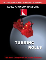
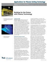
CUTTING, POSITIONING & WELDING EQUIPMENT<br />
KOIKE ARONSON RANSOME<br />
The Most Complete Line in the Industry
Table of Contents<br />
Selecting a HTS Positioner.............4<br />
Aronson Series HTS<br />
Fixed Height.............6<br />
Gear Elevating.............7<br />
Ransome Series HTS<br />
Power Elevating..........14<br />
HT Series<br />
180° Tilter..........18<br />
Skyhook..........20<br />
Drop Center..........22<br />
Options..........24<br />
Installation Considerations….…..27<br />
PAGE 3
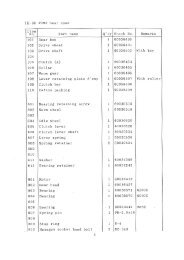
How to Size Head & <strong>Tailstock</strong>s<br />
Weight Capacity<br />
The basic Head and <strong>Tailstock</strong> configuration includes (1)<br />
Powered rotation <strong>Headstock</strong> and a companion Non<br />
Powered <strong>Tailstock</strong>. The <strong>Headstock</strong> supports one end of<br />
the work-piece and imparts rotational motion to the work.<br />
The <strong>Tailstock</strong> merely supports the other end of the workpiece<br />
as it rotates. The first factor in selecting a HTS is to<br />
determine the maximum weight capacity required. The<br />
load should be evenly distributed between the Head and<br />
<strong>Tailstock</strong>, if either supports more than half of the load,<br />
(determined on CG location along the rotational centerline)<br />
an increased capacity model may be required.<br />
Overhung Loads:<br />
Head and tail units are rated for overhanging loads.<br />
Determine the weight and how far off of the table surface<br />
the CG (Center-of-Gravity) of the work-piece will be<br />
located, then select the proper model Positioner.<br />
When head and tail units are used together, the load<br />
weight is shared by both units. As explained below, if the<br />
weight is imposed on a universal joint or clamping fixture,<br />
the distance that the flexible point is off from the table face<br />
determines the overhanging load on the head and tail<br />
units.<br />
Rotation Torque Load:<br />
To find your weldments’ Rotation Torque Load,<br />
multiply the weldment weight in Pounds by the distance<br />
in inches that Center-of-Gravity (CG) will be from the<br />
center of the table. This measurement is taken parallel to<br />
the table surface. Do not exceed the maximum load<br />
torque shown in the “rotation” column.<br />
Fixturing:<br />
Rigidly mounted work pieces between a Head and<br />
<strong>Tailstock</strong> should be avoided if at all Possible.<br />
Misalignment, or inaccurate work pieces can create<br />
stresses that can tear the work form the table or damage<br />
the Positioners, leading to un-safe work conditions or<br />
machine failures.<br />
12 In.<br />
300mm<br />
2,000 Lbs.<br />
907 Kg.<br />
KOIKE ARONSON<br />
PAGE 4
Load Capacity Tables<br />
MODEL<br />
HS2VF<br />
Load off<br />
Rotation CG<br />
Lbs. @ 6"<br />
2,500<br />
Rotation<br />
Torque<br />
In/Lbs.<br />
30,000<br />
Max. Load<br />
between Head<br />
& Tail (Lbs.)<br />
–<br />
CG @<br />
6"<br />
2,500<br />
CG@<br />
12"<br />
2,500<br />
CG@<br />
18"<br />
1,100<br />
CG@<br />
24"<br />
850<br />
CG@<br />
30"<br />
700<br />
CG@<br />
36"<br />
600<br />
CG@<br />
42"<br />
500<br />
TS2<br />
2,500<br />
–<br />
–<br />
2,500<br />
2,500<br />
1,100<br />
850<br />
700<br />
600<br />
500<br />
HTS5VF-GE<br />
5,000<br />
30,000<br />
5,000<br />
–<br />
–<br />
–<br />
–<br />
–<br />
–<br />
–<br />
2H/2T-PE<br />
5,000<br />
30,000<br />
5,000<br />
–<br />
–<br />
–<br />
–<br />
–<br />
–<br />
–<br />
3H/3T-PE 6,000 36,000 – – – – – – –<br />
HS4VF<br />
4,500<br />
54,000<br />
–<br />
4,500<br />
2,700<br />
2,000<br />
1,550<br />
1,300<br />
1,100<br />
950<br />
TS4<br />
4,500<br />
–<br />
–<br />
4,500<br />
2,700<br />
2,000<br />
1,550<br />
1,300<br />
1,100<br />
950<br />
HTS9VF-GE<br />
9,000<br />
54,000<br />
9,000<br />
–<br />
–<br />
–<br />
–<br />
–<br />
–<br />
–<br />
3.5H/3.5T-PE<br />
HS6VF<br />
9,000<br />
6,000<br />
54,000<br />
72,000<br />
9,000<br />
–<br />
–<br />
6,000<br />
–<br />
6,000<br />
–<br />
4,400<br />
–<br />
3,450<br />
–<br />
2,850<br />
–<br />
2,400<br />
–<br />
2,100<br />
TS6<br />
6,000<br />
–<br />
–<br />
6,000<br />
6,000<br />
4,400<br />
3,450<br />
2,850<br />
2,400<br />
2,100<br />
HTS12VF-GE<br />
12,000<br />
72,000<br />
12,000<br />
–<br />
–<br />
–<br />
–<br />
–<br />
–<br />
–<br />
4H/4T-PE<br />
HS10VF<br />
12,000<br />
10,000<br />
72,000<br />
120,000<br />
12,000<br />
–<br />
–<br />
10,000<br />
–<br />
10,000<br />
–<br />
7,350<br />
–<br />
5,850<br />
–<br />
4,850<br />
–<br />
4,100<br />
–<br />
3,500<br />
TS10<br />
10,000<br />
–<br />
–<br />
10,000<br />
10,000<br />
7,350<br />
5,850<br />
4,850<br />
4,100<br />
3,500<br />
HTS20VF-GE<br />
20,000<br />
120,000<br />
20,000<br />
–<br />
–<br />
–<br />
–<br />
–<br />
–<br />
–<br />
5H/5T-PE<br />
HS16VF<br />
20,000<br />
16,000<br />
120,000<br />
192,000<br />
20,000<br />
–<br />
–<br />
16,000<br />
–<br />
16,000<br />
–<br />
12,000<br />
–<br />
9,600<br />
–<br />
8,000<br />
–<br />
6,850<br />
–<br />
6,000<br />
TS16<br />
16,000<br />
–<br />
–<br />
16,000<br />
16,000<br />
12,000<br />
9,600<br />
8,000<br />
6,850<br />
6,000<br />
HTS32VF-GE<br />
32,000<br />
192,000<br />
32,000<br />
–<br />
–<br />
–<br />
–<br />
–<br />
–<br />
–<br />
6H/6T-PE<br />
HS20VF<br />
32,000<br />
20,000<br />
192,000<br />
240,000<br />
32,000<br />
–<br />
–<br />
20,000<br />
–<br />
20,000<br />
–<br />
15,000<br />
–<br />
12,000<br />
–<br />
10,000<br />
–<br />
8,550<br />
–<br />
7,500<br />
TS20<br />
20,000<br />
–<br />
–<br />
20,000<br />
20,000<br />
15,000<br />
12,000<br />
10,000<br />
8,550<br />
7,500<br />
HTS40VF-GE<br />
HS25VF<br />
40,000<br />
25,000<br />
240,000<br />
300,000<br />
40,000<br />
–<br />
–<br />
25,000<br />
–<br />
25,000<br />
–<br />
18,900<br />
–<br />
15,200<br />
–<br />
12,750<br />
–<br />
10,950<br />
–<br />
9,600<br />
TS25<br />
25,000<br />
–<br />
–<br />
25,000<br />
25,000<br />
18,900<br />
15,200<br />
12,750<br />
10,950<br />
9,600<br />
HTS50VF-GE<br />
50,000<br />
300,000<br />
50,000<br />
–<br />
–<br />
–<br />
–<br />
–<br />
–<br />
–<br />
7H/7T-PE<br />
HS30VF<br />
50,000<br />
30,000<br />
300,000<br />
360,000<br />
50,000<br />
–<br />
–<br />
30,000<br />
–<br />
30,000<br />
–<br />
22,850<br />
–<br />
18,450<br />
–<br />
15,500<br />
–<br />
13,350<br />
–<br />
11,600<br />
TS30<br />
HTS60VF-GE<br />
30,000<br />
60,000<br />
–<br />
360,000<br />
–<br />
60,000<br />
8H/8T-PE 80,000 480,000 80,000 – – – – – – –<br />
HS45VF<br />
TS45<br />
HTS90VF-GE<br />
45,000<br />
45,000<br />
90,000<br />
540,000<br />
–<br />
540,000<br />
–<br />
–<br />
90,000<br />
10H/10T-PE 120,000 720,000 120,000 – – – – – – –<br />
HS80VF<br />
80,000<br />
960,000<br />
–<br />
30,000<br />
–<br />
45,000<br />
45,000<br />
–<br />
80,000<br />
30,000<br />
–<br />
45,000<br />
45,000<br />
–<br />
80,000<br />
22,850<br />
–<br />
34,400<br />
34,400<br />
–<br />
61,150<br />
18,450<br />
–<br />
27,850<br />
27,850<br />
–<br />
49,500<br />
15,500<br />
–<br />
23,400<br />
23,400<br />
–<br />
41,600<br />
13,350<br />
–<br />
20,150<br />
20,150<br />
–<br />
35,850<br />
11,600<br />
–<br />
17,700<br />
17,700<br />
–<br />
31,500<br />
TS80<br />
80,000<br />
–<br />
–<br />
80,000<br />
80,000<br />
61,150<br />
49,500<br />
41,600<br />
35,850<br />
31,500<br />
HTS160VF-GE<br />
160,000<br />
960,000<br />
160,000<br />
–<br />
–<br />
–<br />
–<br />
–<br />
–<br />
–<br />
16H/16T-PE<br />
HS120VF<br />
160,000<br />
120,000<br />
960,000<br />
1,440,000<br />
160,000<br />
–<br />
–<br />
120,000<br />
–<br />
92,000<br />
–<br />
75,000<br />
–<br />
63,000<br />
–<br />
54,000<br />
–<br />
48,000<br />
–<br />
42,000<br />
TS120<br />
HTS240VF-GE<br />
120,000<br />
240,000<br />
–<br />
1,440,000<br />
–<br />
240,000<br />
120,000<br />
–<br />
92,000<br />
–<br />
75,000<br />
–<br />
63,000<br />
–<br />
54,000<br />
–<br />
48,000<br />
–<br />
42,000<br />
–<br />
***All dimensions are for reference only and subject to change without notice.<br />
PAGE 5
ARONSONSeries<br />
Fixed Height<br />
2.5 ton thru 10 ton Capacity<br />
Features<br />
Piloted tables for centering<br />
loads<br />
NEMA 12 Electricals<br />
Full length table slots<br />
Chassis mounted weld<br />
current grounding blocks<br />
Low voltage hand control<br />
pendants<br />
50:1 Variable speed drives<br />
AC brake motors<br />
<strong>Koike</strong> Aronson / Ransome manufactures Head and <strong>Tailstock</strong><br />
Positioners with a wide range of capacities and options. These units<br />
are a strong and simple solution for the rotation of long elliptical work<br />
pieces. When used together, they require much less floor space than<br />
a Gear Driven Positioner of similar capacity.<br />
Head and <strong>Tailstock</strong> Positioners can be used like a lathe to maintain<br />
rotation around the horizontal axis. High quality positioned welds can<br />
be performed while saving production and handling costs. Depending<br />
on the industrial application these Positioners may be mounted on<br />
fixed bases, manually adjustable bases or powered bases.<br />
Standard hand pendant provided with all models<br />
Capacities from 5,000 to 20,000 pounds<br />
Between Head and <strong>Tailstock</strong><br />
KOIKE ARONSON, INC. / RANSOME<br />
Optional foot switch controls available<br />
PAGE 6
Specifications<br />
HTS 5 thru HTS 20<br />
MODEL HTS5 HTS9 HTS12 HTS20<br />
Load Capacity, Lbs. (kg) 5,000 Lbs. (2268)<br />
Max. Between Head & Tail<br />
Overhung load 6” CG Height 2,500 (1134)<br />
on either or Both 12” CG Height<br />
Head or <strong>Tailstock</strong> 18” CG Height<br />
24” CG Height<br />
30” CG Height<br />
36” CG Height<br />
42” CG Height<br />
48” CG Height<br />
54” CG Height<br />
60” CG Height<br />
72” CG Height<br />
1,500 (680)<br />
1,100 (499)<br />
850 (386)<br />
700 (317)<br />
600 (272)<br />
500 (227)<br />
450 (204)<br />
400 (181)<br />
350 (159)<br />
300 (136)<br />
9,000 Lbs. (4082)<br />
4,500 (2041)<br />
2,700 (1225)<br />
2,000 (907)<br />
1,550 (703)<br />
1,300 (590)<br />
1,100 (499)<br />
950 (431)<br />
871 (395)<br />
783 (355)<br />
711 (323)<br />
651 (296)<br />
12,000 Lbs. (5443)<br />
6,000 (2721)<br />
6,000 (2721)<br />
4,400 (1996)<br />
3,450 (1565)<br />
2,850 (1293)<br />
2,400 (1089)<br />
2,100 (952)<br />
1,850 (839)<br />
1,650 (748)<br />
1,500 (680)<br />
1,250 (567)<br />
20,000 Lbs. (9072)<br />
10,000 (4536)<br />
10,000 (4536)<br />
7,350 (3334)<br />
5,850 (2653)<br />
4,850 (2200)<br />
4,100 (1860)<br />
3,600 (1633)<br />
3,200 (1451)<br />
2,850 (1293)<br />
2,600 (1179)<br />
2,200 (998)<br />
<strong>Tailstock</strong> model TS 2 TS 4 TS 6 TS 10<br />
<strong>Headstock</strong> model HS 2VF HS 4VF HS 6VF HS 10VF<br />
Rotation: Torque, In-Lbs. (N.m) 30,000 (3390) 54,000 (6102) 72,000 (8136) 120,000 (13560)<br />
Rotation: Speed Range<br />
Motor HP (AC variable Frequency)<br />
1.13 - 0.02 rpm<br />
1-1/2<br />
1.2 - 0.02 rpm<br />
3<br />
1.3 - 0.03 rpm<br />
3<br />
1.0 - 0.02 rpm<br />
5<br />
Pendant cable length 20' 20' 20' 20'<br />
Ground current (Amps) 1500 1500 2000 2000<br />
A: Rotation centerline height<br />
Matching Positioner<br />
B: Table Size (Square)<br />
C: Max. Clamping Dia.<br />
D: No. of slots and width<br />
E: Table Thickness<br />
Pilot hole and Depth<br />
Thru-hole<br />
F: Table nut thread<br />
27-¾” (705)<br />
HD25-HD45<br />
30”(762)<br />
38-½” (978)<br />
(4) 13/16” (21)<br />
1-¾” (44)<br />
3.130” x ½”<br />
none<br />
3/4-”10<br />
27-¾” (705)<br />
HD25-HD45<br />
30”(762)<br />
38-½” (978)<br />
(4) 13/16” (21)<br />
1-¾” (44)<br />
3.130” x ½”<br />
none<br />
3/4-”10<br />
36” (914)<br />
HD60<br />
48”(1219)<br />
64” (1626)<br />
(4) 13/16” (21)<br />
2” (51)<br />
3.130” x ½”<br />
none<br />
3/4-”10<br />
36” (914)<br />
HD100<br />
48”(1219)<br />
64” (1626)<br />
(4) 13/16” (21)<br />
2” (51)<br />
3.130” x ½”<br />
none<br />
3/4-”10<br />
Dim G 30" (762) 30" (762) 36" (914) 36" (914)<br />
Dim H 30-¾" (781) 30-¾" (781) 43" (1092) 43-¾" (1111)<br />
Dim I 27" (686) 27" (686) 39" (991) 39" (991)<br />
Dim J 27" (686) 27" (686) 34" (864) 34" (864)<br />
Dim K 1-½" (38) 1-½" (38) 1" (25) 1" (25)<br />
Dim L 13/16" (20.6) 13/16" (20.6) 7/8" (22) 7/8" (22)<br />
Dim M 3/8" (9) 3/8" (9) 1/2" (13) 1/2" (13)<br />
Dim N 2" (51) 2" (51) 2-½" (63) 2-½" (63)<br />
Dim O 32" (813) 32" (813) 38-½" (978) 38-½" (978)<br />
Approx. Weight HS Lb (Kg) 1,210 (549) 1,270 (576) 2,650 (1202) 3,250 (1474)<br />
Approx. Weight TS Lb (kg) 950 (431) 1,015 (460) 2,354 (1068) 2,605 (1182)<br />
Standard Voltage 460/3/60 460/3/60 460/3/60 460/3/60<br />
***All dimensions are for reference only and subject to change without notice.<br />
<strong>Koike</strong> Aronson Inc.<br />
P.O. Box 307, Arcade, New York 14009<br />
Phone (585) 492-2400 Fax (585) 457-3517<br />
www.koike.com<br />
PAGE 7
ARONSONSeries<br />
Fixed Height<br />
16 ton thru 120 ton Capacity<br />
Features<br />
Piloted tables for centering<br />
loads<br />
NEMA 12 Electricals<br />
Full length table slots<br />
Chassis mounted weld<br />
current grounding blocks<br />
Low voltage hand control<br />
pendants<br />
50:1 Variable speed drives<br />
AC brake motors<br />
<strong>Koike</strong> Aronson / Ransome manufactures Head and <strong>Tailstock</strong><br />
Positioners with a wide range of capacities and options. These units<br />
are a strong and simple solution for the rotation of long elliptical work<br />
pieces. When used together, they require much less floor space than<br />
a Gear Driven Positioner of similar capacity.<br />
Head and <strong>Tailstock</strong> Positioners can be used like a lathe to maintain<br />
rotation around the horizontal axis. High quality positioned welds can<br />
be performed while saving production and handling costs. Depending<br />
on the industrial application these Positioners may be mounted on<br />
fixed bases, manually adjustable bases or powered bases.<br />
Standard hand pendant provided with all models<br />
Capacities from 32,000 to 240,000 pounds<br />
Between Head and <strong>Tailstock</strong><br />
KOIKE ARONSON, INC. / RANSOME<br />
Optional foot switch controls available<br />
PAGE 8
Specifications<br />
HTS 32 thru HTS 240<br />
MODEL HTS32 HTS40 HTS50 HTS60 HTS90 HTS160 HTS240<br />
Load Capacity, Lbs. (kg)<br />
Max. Between Head & Tail<br />
Overhung load<br />
12” CG Height<br />
on either or Both 18” CG Height<br />
Head or <strong>Tailstock</strong>24”<br />
CG Height<br />
30” CG Height<br />
36” CG Height<br />
42” CG Height<br />
48” CG Height<br />
54” CG Height<br />
60” CG Height<br />
72” CG Height<br />
32,000 Lbs. (14515)<br />
16,000 (7257)<br />
12,000 (5443)<br />
9,600 (4354)<br />
8,000 (3629)<br />
6,850 (3107)<br />
6,000 (2721)<br />
5,300 (2404)<br />
4,800 (2177)<br />
4350 (1973)<br />
3650 (1656)<br />
40,000 Lbs. (18144)<br />
20,000 (9072)<br />
15,000 (6804)<br />
12,000 (5443)<br />
10,000 (4536)<br />
8,550 (3878)<br />
7,500 (3402)<br />
6,650 (3016)<br />
6,000 (2721)<br />
5,450 (2472)<br />
4,600 (2086)<br />
50,000 Lbs. (22680)<br />
25,000 (11340)<br />
18,900 (8573)<br />
15,200 (6895)<br />
12,750 (5783)<br />
10,950 (4967)<br />
9,600 (4354)<br />
8,550 (3878)<br />
7,700 (3493)<br />
7,000 (3175)<br />
5950 (2699)<br />
60,000 Lbs. (27215)<br />
30,000 (13608)<br />
22,850 (10364)<br />
18,450 (8369)<br />
15,500 (7031)<br />
13,350 (6055)<br />
12,200 (5534)<br />
10,450 (4740)<br />
9,400 (4264)<br />
8,550 (3878)<br />
7,250 (3288)<br />
90,000 Lbs. (40823)<br />
45,000 (20214)<br />
34,400 (15603)<br />
27,850 (12632)<br />
23,400 (10614)<br />
20,150 (9140)<br />
17,700 (8028)<br />
15,800 (7167)<br />
14,250 (6464)<br />
13,000 (5897)<br />
11,000 (4989)<br />
160,000 Lbs. (72575)<br />
80,000 (36287)<br />
61,150 (27737)<br />
49,500 (22453)<br />
41,600 (18869)<br />
35,850 (16261)<br />
31,500 (14288)<br />
28,100 (12746)<br />
25,350 (11498)<br />
23,100 (10478)<br />
19,600 (8890)<br />
240,000 Lbs. (108862)<br />
120,000 (54431)<br />
92,000 (41730)<br />
75,000 (34019)<br />
63,000 (28576)<br />
54,000 (24494)<br />
48,000 (21772)<br />
42,000 (19051)<br />
38,000 (17236)<br />
35,000 (15876)<br />
30,000 (13608)<br />
<strong>Tailstock</strong> model TS 16 TS 20 TS 25 TS 30 TS 45 TS 80 TS 120<br />
<strong>Headstock</strong> model HS 16VF HS 20VF HS 25VF HS 30VF HS 45VF HS 80VF HS 120VF<br />
Rotation: Torque, In-Lbs. (N.m) 192,000 (21696) 240,000 (27120) 300,000 (33900) 360,000 (40680) 540,000 (61020) 960,000 (108480) 1,440,000 (162720)<br />
Rotation: Speed Range<br />
Motor HP (AC variable frequency)<br />
0.60 - 0.012 rpm<br />
5<br />
0.50 - 0.010 rpm<br />
5<br />
0.40 - 0.008 rpm<br />
5<br />
0.50 - 0.010 rpm<br />
10<br />
0.50 - 0.010 rpm<br />
10<br />
0.40 - 0.008 rpm<br />
15<br />
Pendant cable length 20' 20' 20' 20' 20' 20' 20'<br />
0.40 - 0.008 rpm<br />
20<br />
Ground current (Amps) 2000 2000 2000 3000 3000 3000 3000<br />
A: Rotation centerline height<br />
Matching Positioner<br />
B: Table Size (Square)<br />
C: Max. Clamping Dia.<br />
D: No. of slots and width<br />
E: Table Thickness<br />
Pilot hole and Depth<br />
Thru-hole<br />
F: Table nut thread<br />
50” (1270)<br />
HD160<br />
54”(1372)<br />
70” (1778)<br />
(4) 1-1/16” (27)<br />
2-½” (64)<br />
8.627” x 1”<br />
8-½" thru<br />
1"-8<br />
50” (1270)<br />
HD240<br />
54”(1372)<br />
70” (1778)<br />
(4) 1-1/16” (27)<br />
2-½” (64)<br />
8.627” x 1”<br />
8-½" thru<br />
1"-8<br />
50” (1270)<br />
HD240<br />
60”(1524)<br />
77” (1956)<br />
(4) 1-1/16” (27)<br />
2-¾” (70)<br />
8.627” x 1”<br />
8-½" thru<br />
1"-8<br />
50” (1270)<br />
—<br />
54”(1372)<br />
70” (1778)<br />
(4) 1-5/16” (33)<br />
2-3/4” (70)<br />
12.253” x 1”<br />
11-7/8" thru<br />
1"-8<br />
50” (1270)<br />
—<br />
54”(1372)<br />
70” (1778)<br />
(4) 1-5/16” (33)<br />
3” (76)<br />
12.253” x 1”<br />
11-7/8" thru<br />
1.25"-7<br />
50” (1270)<br />
—<br />
54”(1372)<br />
70” (1778)<br />
(4) 1-5/16” (33)<br />
3” (76)<br />
12.253” x 1”<br />
11-7/8" thru<br />
1"-8<br />
72” (1829)<br />
—<br />
84”(2134)<br />
108” (2743)<br />
(4) 1-7/8” (48)<br />
3-½” (89)<br />
12.000” x 1-¾”<br />
11-7/8" thru<br />
1-¾"-8<br />
Dim G 48" (1219) 48" (1219) 48" (1219) 50" (1270) 60" (1524) 60" (1524) 72" (1829)<br />
Dim H 48" (1219) 48" (1219) 48" (1219) 52" (1321) 65" (1651) 65" (1651) 80" (2032)<br />
Dim I 46" (1168) 46" (1168) 46" (1168) 46" (1168) 58" (1473) 58" (1473) 76" (1930)<br />
Dim J 46" (1168) 46" (1168) 46" (1168) 46" (1168) 56" (1422) 56" (1422) 68" (1727)<br />
Dim K 1" (25) 1" (25) 1" (25) 2" (51) 2" (51) 2" (51) 2" (51)<br />
Dim L 1-1/16" (27) 1-1/16" (27) 1-1/16" (27) 1-5/8" (41) 2-1/8" (54) 2-1/8" (54) 2-1/8" (54)<br />
Dim M 1-½" (38) 1-½" (38) 1-½" (38) ¾" (19) 1" (25) 1" (25) 1-¼" (32)<br />
Dim N 2-¾" (70) 2-¾" (70) 2-¾" (70) 2-¾" (70) 3-½" (89) 3-½" (89) 4" (102)<br />
Dim O 50-¾" (1289) 50-¾" (1289) 50-¾" (1289) 52-¾" (1340) 63-½" (1613) 63-½" (1613) 74" (1880)<br />
Approx. Weight HS Lb (Kg) 5,100 (2313) 5,300 (2404) 5,820 (2640) 6,000 (2721) 9,532 (4234) 10,000 (4536) 21,850 (9910)<br />
Approx. Weight TS Lb (kg) 4,255 (1930) 4255 (1930) 4,930 (2236) 5,000 (2268) 7,891 (3579) 8,960 (4064) 19,480 (8836)<br />
Standard Voltage 460/3/60 460/3/60 460/3/60 460/3/60 460/3/60 460/3/60 460/3/60<br />
***All dimensions are for reference<br />
only and subject to change without notice.<br />
<strong>Koike</strong> Aronson Inc.<br />
P.O. Box 307, Arcade, New York 14009<br />
Phone (585) 492-2400 Fax (585) 457-3517<br />
www.koike.com<br />
PAGE 9
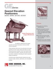
ARONSONSeries<br />
Geared Elevation<br />
2.5 ton thru 10 ton<br />
Features<br />
Multiple lift drive pinions<br />
50:1 AC Variable speed<br />
rotation<br />
Low efficiency gear-boxes<br />
for safety<br />
360° continuous rotation<br />
Low voltage hand control<br />
pendants<br />
<strong>Koike</strong> Aronson / Ransome geared elevation Head and <strong>Tailstock</strong><br />
Positioners provide all the advantages of standard fixed height models but<br />
also include adjustable elevation to provide ergonomic working heights and<br />
improve safety.<br />
Gear rack cut into vertical posts and multiple interlocked drive pinions<br />
provide the highest degree of safety in the industry. NEMA 12 electricals,<br />
ground blocks and tapered roller bearings are provided on every unit. Lifttime<br />
lubrication and sealed drive units insure many years of trouble free<br />
service. Special engineered elevation heights and options are also available.<br />
<strong>Headstock</strong> and <strong>Tailstock</strong> axes on <strong>Koike</strong> Aronson Ransome systems are<br />
electronically synchronized to prevent workpiece / fixture skewing. Both axes<br />
are driven by an encoded motor, controlled by a drive with internal PLC<br />
capabilities. Encoder information from both axes is fed back to the <strong>Tailstock</strong><br />
drive. The <strong>Tailstock</strong> encoder provides closed-loop position information to the<br />
<strong>Tailstock</strong> drive, which in turn, follows the reference signal from the<br />
<strong>Headstock</strong> encoder. The <strong>Headstock</strong> drive and motor respond to commands<br />
from the operator control pendant (or optionally a supervisory programmable<br />
control system). When the <strong>Headstock</strong> moves, the <strong>Tailstock</strong> automatically<br />
follows, step-for-step, based upon encoder feedback. If any errors are<br />
detected internally, or from external devices by either drive, the system will<br />
immediately halt to prevent workpiece/fixture skewing.<br />
Travel cars for multiple<br />
lengths available<br />
Standard hand pendant provided with all models<br />
Capacities from 5,000 to 20,000 pounds<br />
Between Head and <strong>Tailstock</strong><br />
KOIKE ARONSON, INC. / RANSOME<br />
PAGE 10
Specifications<br />
HTS 5-GE thru HTS 20-GE<br />
MODEL HTS5-GE HTS9-GE HTS12-GE HTS20-GE<br />
Load Capacity, Lbs. (kg)<br />
Max. Between Head & Tail<br />
Overhung load<br />
on either or Both<br />
Head or <strong>Tailstock</strong><br />
6” CG Height<br />
12” CG Height<br />
18” CG Height<br />
24” CG Height<br />
30” CG Height<br />
36” CG Height<br />
42” CG Height<br />
48” CG Height<br />
54” CG Height<br />
60” CG Height<br />
72” CG Height<br />
5,000 Lbs. (2268)<br />
2,500 (1134)<br />
1,500 (680)<br />
1,100 (499)<br />
850 (386)<br />
700 (317)<br />
600 (272)<br />
500 (227)<br />
450 (204)<br />
400 (181)<br />
350 (159)<br />
300 (136)<br />
9,000 Lbs. (4082)<br />
4,500 (2041)<br />
2,700 (1225)<br />
2,000 (907)<br />
1,550 (703)<br />
1,300 (590)<br />
1,100 (499)<br />
982 (446)<br />
871 (395)<br />
783 (355)<br />
711 (323)<br />
651 (296)<br />
12,000 Lbs. (5443)<br />
6,000 (2721)<br />
6,000 (2721)<br />
4,400 (1996)<br />
3,450 (1565)<br />
2,850 (1293)<br />
2,400 (1089)<br />
2,100 (952)<br />
1,850 (839)<br />
1,650 (748)<br />
1,500 (680)<br />
1,250 (567)<br />
***All dimensions are for reference only and subject to change without notice.<br />
20,000 Lbs. (9072)<br />
10,000 (4536)<br />
10,000 (4536)<br />
7,350 (3334)<br />
5,850 (2653)<br />
4,850 (2200)<br />
4,100 (1860)<br />
3,600 (1633)<br />
3,200 (1451)<br />
2,850 (1293)<br />
2,600 (1179)<br />
2,200 (998)<br />
Rotation: Torque, In-Lbs. (N.m) 30,000 (3390) 54,000 (6102) 72,000 (8136) 120,000 (13560)<br />
Rotation: Speed Range<br />
2.0 - 0.04 rpm 2.0 - 0.04 rpm 1.3 - 0.03 rpm 1.2 - 0.02 rpm<br />
Motor HP (AC variable Frequency) 1-1/2<br />
2<br />
2<br />
5<br />
Pendant cable length 20' 20' 20' 20'<br />
Ground current (Amps) 1500 1500 2000 2000<br />
A: CL height Range In(mm)<br />
Elevation speed ipm(mm/min)<br />
Motor HP (Qty 2)<br />
30-54 (762-1362)<br />
34 ipm (864)<br />
1<br />
30-54 (762-1362)<br />
30 ipm (762)<br />
2<br />
27.5-79.5 (699-2019)<br />
21 ipm (533)<br />
2<br />
27.5-79.5 (699-2019)<br />
21 ipm (533)<br />
3<br />
B: Table Size (Round)<br />
C: Max. Clamping Dia.<br />
D: No. of slots and width<br />
E: Table Thickness<br />
Pilot hole and Depth<br />
Thru-hole<br />
F: Table nut thread<br />
30”(762)<br />
27" (686)<br />
(4) 13/16” (21)<br />
1-¾” (44)<br />
3.130” x ½”<br />
none<br />
3/4-”10<br />
30”(762)<br />
27" (686)<br />
(4) 13/16” (21)<br />
1-¾” (44)<br />
3.130” x ½”<br />
none<br />
3/4-”10<br />
36”(914)<br />
33” (838)<br />
(4) 13/16” (21)<br />
2” (50)<br />
9.127” x 1-½”<br />
9" Thru<br />
3/4-”10<br />
36”(914)<br />
33” (838)<br />
(4) 13/16” (21)<br />
2” (50)<br />
9.127” x 1-½”<br />
9" Thru<br />
3/4-”10<br />
Dim G 39" (991) 39" (991) 48" (1219) 48" (1219)<br />
Dim H 43" (1092) 43" (1092) 60" (1524) 60" (1524)<br />
Dim I 41-½" (1054) 41-½" (1054) 50" (1270) 50" (1270)<br />
Dim J 37" (940) 37" (940) 45-½" (1156) 45-½" (1156)<br />
Dim K 1" (25) 1" (25) 1-¼" (32) 1-¼" (32)<br />
Dim L 13/16" (21) 13/16" (21) 1-1/16" (25) 1-1/16" (25)<br />
Dim M 3/8" (9) 3/8" (9) 1-½" (38) 1-½" (38)<br />
Dim N 2" (51) 2" (51) 4" (102) 4" (102)<br />
Dim O 41" (1041) 41" (1041) 50" (1270) 50" (1270)<br />
Dim P (Max overall height) 69" (1753) 69" (1753) 116" (2946) 116" (2946)<br />
Approx. Weight HS Lb (Kg) 4,610 (2091) 4,800 (2177) 9,000 (4082) 9,140 (4146)<br />
Approx. Weight TS Lb (kg) 4,540 (2059) 4,650 (2110) 8,450 (3832) 8,785 (3985)<br />
Standard Voltage 460/3/60 460/3/60 460/3/60 460/3/60<br />
<strong>Koike</strong> Aronson Inc.<br />
P.O. Box 307, Arcade, New York 14009<br />
Phone (585) 492-2400 Fax (585) 457-3517<br />
www.koike.com<br />
PAGE 11
Constant Centerline, Steel wheels, Tachometers, foot controls and special engineered designs available.<br />
ARONSONSeries<br />
Geared Elevation<br />
16 ton thru 120 ton Capacity<br />
Features<br />
Multiple lift drive pinions<br />
50:1 AC Variable speed<br />
rotation<br />
Low efficiency gear-boxes<br />
for safety<br />
360° continuous rotation<br />
Low voltage hand control<br />
pendants<br />
<strong>Koike</strong> Aronson / Ransome geared elevation Head and <strong>Tailstock</strong><br />
Positioners provide all the advantages of standard fixed height models but also<br />
include adjustable elevation to provide ergonomic working heights and improve<br />
safety.<br />
Gear rack cut into vertical posts and multiple interlocked drive pinions provide<br />
the highest degree of safety in the industry. NEMA 12 electricals, ground blocks<br />
and tapered roller bearings are provided on every unit. Lift-time lubrication and<br />
sealed drive units insure many years of trouble free service. Special engineered<br />
elevation heights and options are also available.<br />
<strong>Headstock</strong> and <strong>Tailstock</strong> axes on <strong>Koike</strong> Aronson Ransome systems are<br />
electronically synchronized to prevent workpiece / fixture skewing. Both axes are<br />
driven by an encoded motor, controlled by a drive with internal PLC capabilities.<br />
Encoder information from both axes is fed back to the <strong>Tailstock</strong> drive. The <strong>Tailstock</strong><br />
encoder provides closed-loop position information to the <strong>Tailstock</strong> drive, which in<br />
turn, follows the reference signal from the <strong>Headstock</strong> encoder. The <strong>Headstock</strong><br />
drive and motor respond to commands from the operator control pendant (or<br />
optionally a supervisory programmable control system). When the <strong>Headstock</strong><br />
moves, the <strong>Tailstock</strong> automatically follows, step-for-step, based upon encoder<br />
feedback. If any errors are detected internally, or from external devices by either<br />
drive, the system will immediately halt to prevent workpiece/fixture skewing.<br />
Capacities from 32,000 to 240,000 pounds<br />
Between Head and <strong>Tailstock</strong><br />
KOIKE ARONSON, INC. / RANSOME<br />
Travel cars for multiple<br />
lengths available<br />
Standard hand pendant provided with all models<br />
PAGE 12
Specifications<br />
HTS 32-GE thru HTS 240-GE<br />
Load Capacity, Lbs. (kg)<br />
Max. Between Head & Tail<br />
Overhung load<br />
on either or Both<br />
Head or <strong>Tailstock</strong><br />
MODEL HTS32-GE HTS40-GE HTS50-GE HTS60-GE HTS90-GE HTS160-GE<br />
12” CG Height<br />
18” CG Height<br />
24” CG Height<br />
30” CG Height<br />
36” CG Height<br />
42” CG Height<br />
48” CG Height<br />
54” CG Height<br />
60” CG Height<br />
72” CG Height<br />
32,000 Lbs. (14515)<br />
16,000 (7264)<br />
12,000 (5448)<br />
9,600 (4358)<br />
8,000 (3632)<br />
6,857 (3113)<br />
6,000 (2724)<br />
5,333 (2421)<br />
4,800 (2179)<br />
4,364 (1981)<br />
4,000 (1816)<br />
40,000 Lbs. (18144)<br />
20,000 (9072)<br />
15,000 (6804)<br />
12,000 (5443)<br />
10,000 (4536)<br />
8,550 (3878)<br />
7,500 (3402)<br />
6,550 (3016)<br />
6,000 (2721)<br />
5,450 (2472)<br />
4,600 (2086)<br />
50,000 Lbs. (22680)<br />
25,000 (11350)<br />
18,900 (8581)<br />
15,193 (6898)<br />
12,702 (5767)<br />
10,912 (4954)<br />
9,565 (4343)<br />
8,514 (3865)<br />
7,670 (3482)<br />
6,979 (3168)<br />
6,402 (2907)<br />
60,000 Lbs. (27215)<br />
30,000 (13608)<br />
22,850 (10364)<br />
18,450 (8369)<br />
15,500 (7031)<br />
13,350 (6055)<br />
12,200 (5534)<br />
10,450 (4740)<br />
9,400 (4264)<br />
8,530 (3878)<br />
7,850 (3288)<br />
90,000 Lbs. (40823)<br />
45,000 (20214)<br />
34,400 (15603)<br />
27,850 (12632)<br />
23,400 (10614)<br />
20,150 (9140)<br />
17,700 (8028)<br />
15,800 (7167)<br />
14,250 (6464)<br />
13,000 (5897)<br />
11,000 (4989)<br />
160,000 Lbs. (72575)<br />
80,000 (36287)<br />
61,150 (27737)<br />
49,500 (22453)<br />
41,600 (18869)<br />
35,850 (16261)<br />
31,500 (14288)<br />
28,100 (12746)<br />
25,350 (11498)<br />
23,100 (10478)<br />
19,600 (8890)<br />
Rotation: Torque, In-Lbs. (N.m) 192,000 (21696) 240,000 (27120) 300,000 (33900) 360,000 (40680) 540,000 (61020) 960,000 (108480)<br />
Rotation: Speed Range<br />
0.60 - 0.012 rpm 0.50 - 0.01 rpm 0.60 - 0.012 rpm 0.50 - 0.01 rpm 0.50 - 0.01 rpm 0.40 - 0.008 rpm<br />
Motor HP (AC variable Frequency)<br />
5<br />
5<br />
5<br />
10<br />
15<br />
15<br />
Pendant cable length 20' 20' 20' 20' 20' 20'<br />
Ground current (Amps) 2000 2000 2000 3000 3000 3000<br />
A: CL height Range In(mm)<br />
Elevation speed ipm(mm/min)<br />
Motor HP (Qty 2)<br />
28"-80" (711-2032)<br />
19 ipm (483)<br />
5<br />
28"-80" (711-2032)<br />
15 ipm (381)<br />
5<br />
30-3/4"-82-3/4" (781-2102)<br />
21 ipm (533)<br />
7-1/2<br />
30-3/4"-82-3/4" (781-2102)<br />
21 ipm (533)<br />
10<br />
30-3/4"-82-3/4" (781-2102)<br />
21 ipm (533)<br />
20<br />
52-½ -112-½ (1333-2857)<br />
18 ipm (457)<br />
25<br />
B: Table Size (Round)<br />
C: Max. Clamping Dia.<br />
D: No. of slots and width<br />
E: Table Thickness<br />
Pilot hole and Depth<br />
Thru-hole<br />
F: Table nut thread<br />
36”(914)<br />
33" (838)<br />
(4) 1-1/16” (27)<br />
2-½” (63)<br />
8.627" x 1-½”<br />
8-½" Thru<br />
1"-8<br />
36”(914)<br />
33" (838)<br />
(4) 1-1/16” (27)<br />
2-½” (63)<br />
8.627” x 1-½”<br />
8-½" Thru<br />
1"-8<br />
48”(1219)<br />
43” (1092)<br />
(4) 1-1/16” (27)<br />
2-½” (63)<br />
8.627” x 1-½”<br />
8-½" Thru<br />
1"-8<br />
48”(1219)<br />
43” (1092)<br />
(4) 1-1/16” (27)<br />
2-¾” (70)<br />
12.253” x 1”<br />
11-7/8" Thru<br />
1"-8<br />
48”(1219)<br />
43” (1092)<br />
(4) 1-1/16” (27)<br />
3” (76)<br />
12.253” x 1”<br />
11-7/8" Thru<br />
1"-8<br />
66”(1676)<br />
62” (1575)<br />
(4) 1-5/16” (33)<br />
3” (76)<br />
12.253” x 1”<br />
11-7/8" Thru<br />
1-¼"-7<br />
Dim G 48" (1219) 48" (1219) 73" (1854) 73" (1854) 73" (1854) 108" (2743)<br />
Dim H 60" (1524) 60" (1524) 84" (2134) 84" (2134) 84" (2134) 84" (2134)<br />
Dim I 50" (1270) 50" (1270) 64" (1626) 64" (1626) 64" (1626) 64" (1626)<br />
Dim J 45-½" (1156) 45-½" (1156) 69" (1753) 69" (1753) 69" (1753) 104" (2642)<br />
Dim K 1-¼" (32) 1-¼" (32) 2" (51) 2" (51) 2" (51) 2" (51)<br />
Dim L 1-1/16" (25) 1-1/16" (25) 1-5/8" (41) 1-5/8" (41) 1-5/8" (41) 1-5/8" (41)<br />
Dim M 2" (51) 2" (51) 11" (279) 11" (279) 11" (279) 11" (279)<br />
Dim N 5" (127) 5" (127) 7-¼" (184) 9" (229) 3-5/8" (92) 9" (229)<br />
Dim O 51-3/8" (1305) 51-3/8" (1305) 76-¾" (1949) 77-½" (1696) 77" (1956) 111" (2819)<br />
Dim P (Max overall height) 116-½" (2959) 116-½" (2959) 128-¼" (3258) 127-½" (3239) 137-½" (3493) 160" (4064)<br />
Approx. Weight HS Lb (Kg) 13,110 (5947) 13,110 (5947) 14,505 (6580) 15,500 (7030) 21,000 (9525) 23,000 (10433)<br />
Approx. Weight TS Lb (kg) 11,950 (5421) 11,950 (5421) 13,460 (6105) 14,660 (6650) 20,080 (9108) 22,000 (9979)<br />
Standard Voltage 460/3/60 460/3/60 460/3/60 460/3/60 460/3/60 460/3/60<br />
***All dimensions are for<br />
reference only and subject to<br />
change without notice.<br />
<strong>Koike</strong> Aronson Inc.<br />
P.O. Box 307, Arcade, New York 14009<br />
Phone (585) 492-2400 Fax (585) 457-3517<br />
www.koike.com<br />
PAGE 13
Constant Centerline, Steel wheels, Tachometers, foot controls and special engineered designs available.<br />
RANSOMESeries<br />
Ball Screw Elevation<br />
2.5 ton thru 10 ton<br />
Features<br />
Low efficiency gear-boxes<br />
for safety<br />
Ball screw jacks for high<br />
duty cycles<br />
Machined tables<br />
Low voltage hand control<br />
pendants<br />
The Powered Elevation design makes maximum use of proven<br />
commercially available components, both in the elevation and rotation<br />
systems.<br />
Elevation is by means of commercial Ball screw jacks for high duty<br />
cycle operation and driven by a worm/wormgear arrangement. The<br />
elevation axis uses two of these screw jacks for redundancy, coupled<br />
together and driven by a common motor. Belts, chains, and transfer gears<br />
are no longer utilized in the design.<br />
Guidance is provided by means of wide, large diameter cam follower<br />
bearings on flat guide-ways. Cam follower contact with the guide-ways is<br />
adjustable for wear. Guidance is provided on the front, back, and sides of<br />
two columns that rigidly support the cantilevered load.<br />
<strong>Headstock</strong> and <strong>Tailstock</strong> axes on <strong>Koike</strong> Aronson Ransome systems<br />
are electronically synchronized to prevent workpiece / fixture skewing. Both<br />
axes are driven by an encoded motor, controlled by a drive with internal<br />
PLC capabilities. Encoder information from both axes is fed back to the<br />
<strong>Tailstock</strong> drive. The <strong>Tailstock</strong> encoder provides closed-loop position<br />
information to the <strong>Tailstock</strong> drive, which in turn, follows the reference signal<br />
from the <strong>Headstock</strong> encoder. The <strong>Headstock</strong> drive and motor respond to<br />
commands from the operator control pendant (or optionally a supervisory<br />
programmable control system). When the <strong>Headstock</strong> moves, the <strong>Tailstock</strong><br />
automatically follows, step-for-step, based upon encoder feedback. If any<br />
errors are detected internally, or from external devices by either drive, the<br />
system will immediately halt to prevent workpiece/fixture skewing.<br />
Capacities from 5,000 to 20,000 pounds<br />
Between Head and <strong>Tailstock</strong><br />
KOIKE ARONSON, INC. / RANSOME<br />
50:1 AC Variable speed<br />
drives<br />
Boots on elevation jacks<br />
protect screws from debris<br />
Standard hand pendant provided with all models<br />
Optional foot switch controls available<br />
PAGE 14
Specifications<br />
2H/2T-PE thru 5H/5T-PE<br />
MODEL 2H/2T-PE 3H/3T-PE 3.5H/3.5T-PE 4H/4T-PE 4.5H/4.5T-PE 5H/5T-PE<br />
Load Capacity, Lbs. (kg)<br />
Max. Between Head & Tail<br />
12” CG Height<br />
18” CG Height<br />
24” CG Height<br />
30” CG Height<br />
36” CG Height<br />
42” CG Height<br />
5,000 Lbs. (2268)<br />
2,500 (1134)<br />
2,030 (921)<br />
1,710 (776)<br />
1,470 (667)<br />
1,295 (587)<br />
1,155 (524)<br />
6,000 Lbs. (2722)<br />
3,000 (1361)<br />
2,300 (1043)<br />
1,900 (862)<br />
1,600 (726)<br />
1,400 (635)<br />
1,200 (544)<br />
9,000 Lbs. (4082)<br />
4,500 (2041)<br />
3,700 (1678)<br />
3,100 (1406)<br />
2,700 (1225)<br />
2,400 (1089)<br />
2,200 (998)<br />
12,000 Lbs. (5443)<br />
6,000 (2722)<br />
4,980 (2259)<br />
4,260 (1932)<br />
3,720 (1687)<br />
3,300 (1497)<br />
2,970 (998)<br />
16,000 Lbs. (7257)<br />
8,000 (3629)<br />
6,000 (2722)<br />
4,800 (2177)<br />
4,000 (1814)<br />
3,400 (1542)<br />
3,000 (1361)<br />
***All dimensions are for reference only and subject to change without notice.<br />
20,000 Lbs. (9072)<br />
10,000 (4536)<br />
8,400 (3810)<br />
7,200(3266)<br />
6,300 (2858)<br />
5,600 (2540)<br />
5,100 (2313)<br />
Rotation: Torque, In-Lbs. (N.m) 30,000 (3390) 36,000 (4068) 54,000 (6102) 72,000 (8136) 96,000 (10848) 120,000 (13560)<br />
Rotation: Speed Range<br />
1.0 - 0.02 rpm 1.0 - 0.02 rpm 1.0 - 0.02 rpm 0.92 - 0.01 rpm 1.0 - 0.02 rpm 1.0 - 0.02 rpm<br />
Motor HP (AC variable Frequency)<br />
1<br />
1-1/2<br />
2<br />
2<br />
3<br />
5<br />
Pendant cable length 20' 20' 20' 20' 20' 20'<br />
Ground current (Amps) 1500 1500 2000 2000 2000 2000<br />
A: CL height Range In(mm)<br />
Elevation speed ipm(mm/min)<br />
Motor HP (Qty 2)<br />
22"-52" (559-1321)<br />
22 ipm (559)<br />
1-1/2<br />
22.25"-52.25"<br />
23 ipm (559)<br />
2<br />
22.25"-52.25"<br />
23 ipm (559)<br />
2<br />
26"-56" (660-1422)<br />
27 ipm (686)<br />
2<br />
27-½"-79-½" (699-2019)<br />
20 ipm (508)<br />
2<br />
27-½"-79-½" (699-2019)<br />
20 ipm (508)<br />
2<br />
B: Table Size (Round)<br />
C: Max. Clamping Dia.<br />
D: No. of slots and width<br />
E: Table Thickness<br />
Pilot hole and Depth<br />
Thru-hole<br />
F: Table nut thread<br />
36”(914)<br />
33" (838)<br />
(4) 13/16” (21)<br />
7/8” (22)<br />
2.252” x ¾”<br />
2" Thru<br />
¾"-10<br />
40”(1016)<br />
37" (940)<br />
(4) 13/16” (21)<br />
7/8” (22)<br />
2.252” x ¾”<br />
2" Thru<br />
¾"-10<br />
40”(1016)<br />
37" (940)<br />
(4) 13/16” (21)<br />
7/8” (22)<br />
2.252” x ¾”<br />
2" Thru<br />
¾"-10<br />
48”(1219)<br />
45” (1143)<br />
(4) 13/16” (21)<br />
7/8” (22)<br />
6.00” x ½”<br />
2-¾" Thru<br />
¾"-10<br />
48”(1219)<br />
45” (1143)<br />
(4) 1-1/8” (29)<br />
7/8” (22)<br />
6.00” x 2”<br />
5-½" Thru<br />
1"-8<br />
48”(1219)<br />
45” (1143)<br />
(4) 1-1/8” (29)<br />
7/8” (22)<br />
6.00” x 3”<br />
6" Thru<br />
1"-8<br />
Dim G 47-½" (1207) 47-½" (1207) 47-½" (1207) 47-½" (1207) 47-½" (1207) 47-½" (1207)<br />
Dim H 58" (1473) 58" (1473) 58" (1473) 58" (1473) 62" (1575) 62" (1575)<br />
Dim I 52" (1321) 52" (1321) 52" (1321) 52" (1321) 56" (1422) 56" (1422)<br />
Dim J 43-½" (1105) 43-½" (1105) 43-½" (1105) 43-½" (1105) 43-½" (1105) 43-½" (1105)<br />
Dim K 2" (51) 2" (51) 2" (51) 2" (51) 2" (51) 2" (51)<br />
Dim L 7/8" (22) 7/8" (22) 7/8" (22) 7/8" (22) 7/8" (22) 7/8" (22)<br />
Dim M 2" (51) 2" (51) 2" (51) 2" (51) 2" (51) 2" (51)<br />
Dim N 14-9/16" (370) 8-9/16" (217) 8-9/16" (217) 4-13/16" (122) 4-1/16" (103) 4-1/16" (103)<br />
Dim O 58-5/8" (1489) 60-5/8" (1538) 55-1/2" (1410) 53-3/8" (1356) 53-3/8" (1356) 53-3/8" (1356)<br />
Dim P (Max overall height) 80" (2032) 80" (2032) 80" (2032) 86" (2184) 124-½" (3150) 124-½" (3150)<br />
Approx. Weight HS Lb (Kg) 3,240 (1470) 3,335 (1513) 3,512 (1293) 3,687 (1672) 5,500 (2495) 5,986 (2715)<br />
Approx. Weight TS Lb (kg) 2,732 (1239) 2,845 (1290) 3,296 (1495) 3,534 (1602) 5,780 (2622) 5,443 (2469)<br />
Standard Voltage 460/3/60 460/3/60 460/3/60 460/3/60 460/3/60 460/3/60<br />
TAILSTOCK<br />
HEADSTOCK<br />
<strong>Koike</strong> Aronson Inc.<br />
P.O. Box 307, Arcade, New York 14009<br />
Phone (585) 492-2400 Fax (585) 457-3517<br />
www.koike.com<br />
PAGE 15
RANSOME<br />
Series<br />
Ball Screw Elevation<br />
16 ton thru 80 ton<br />
Features<br />
Low efficiency gear-boxes<br />
for safety<br />
Ball screw jacks for high<br />
duty cycles<br />
Machined tables<br />
Low voltage hand control<br />
pendants<br />
The Powered Elevation design makes maximum use of proven<br />
commercially available components, both in the elevation and guidance<br />
systems.<br />
Elevation is provided by means of commercial Ball screw jacks for high<br />
duty cycle operation and driven by a worm/wormgear arrangement. Elevation<br />
uses two of these screw jacks for redundancy, coupled together and driven by<br />
a common motor. Belts, chains, and transfer gears are no longer utilized in<br />
the design.<br />
Guidance is provided by means of wide, large diameter cam follower<br />
bearing on flat guide-ways or linear ways. Cam follower contact with the<br />
guide-ways is adjustable for wear. Guidance is provided on the front, back,<br />
and sides of two columns that rigidly supports the cantilevered load.<br />
<strong>Headstock</strong> and <strong>Tailstock</strong> axes on <strong>Koike</strong> Aronson Ransome systems are<br />
electronically synchronized to prevent workpiece / fixture skewing. Both axes<br />
are driven by an encoded motor, controlled by a drive with internal PLC<br />
capabilities. Encoder information from both axes is fed back to the <strong>Tailstock</strong><br />
drive. The <strong>Tailstock</strong> encoder provides closed-loop position information to the<br />
<strong>Tailstock</strong> drive, which in turn, follows the reference signal from the <strong>Headstock</strong><br />
encoder. The <strong>Headstock</strong> drive and motor respond to commands from the<br />
operator control pendant (or optionally a supervisory programmable control<br />
system). When the <strong>Headstock</strong> moves, the <strong>Tailstock</strong> automatically follows,<br />
step-for-step, based upon encoder feedback. If any errors are detected<br />
internally, or from external devices by either drive, the system will immediately<br />
halt to prevent workpiece/fixture skewing.<br />
Capacities from 32,000 to 160,000 pounds<br />
Between Head and <strong>Tailstock</strong><br />
KOIKE ARONSON, INC. / RANSOME<br />
50:1 AC Variable speed<br />
drives<br />
Boots on elevation jacks<br />
protect screws from debris<br />
Standard hand pendant provided with all models<br />
Optional foot switch controls available<br />
PAGE 16
Specifications<br />
6H/6T-PE thru 16H/16T-PE<br />
MODEL 6H/6T-PE 7H/7T-PE 8H/8T-PE 10H/10T-PE 16H/16T-PE<br />
Load Capacity, Lbs. (kg)<br />
Max. Between Head & Tail<br />
12” CG Height<br />
18” CG Height<br />
24” CG Height<br />
30” CG Height<br />
36” CG Height<br />
42” CG Height<br />
32,000 Lbs. (14515)<br />
16,000 (7257)<br />
12,900 (5851)<br />
10,800(4899)<br />
9,300 (4218)<br />
8,150 (3697)<br />
7,250 (3289)<br />
50,000 Lbs. (22680)<br />
25,000 (11340)<br />
18,900 (8573)<br />
15,200 (6895)<br />
12,750 (5783)<br />
10,950 (4967)<br />
9,600 (4354)<br />
80,000 Lbs. (36287)<br />
40,000 (18144)<br />
30,700 (13608)<br />
25,000 (11340)<br />
21,000 (9525)<br />
18,200 (8255)<br />
16,000 (7257)<br />
100,000 Lbs. (45359)<br />
50,000 (22680)<br />
37,250 (16896)<br />
29,650 (13449)<br />
24,650 (11181)<br />
21,100 (9571)<br />
18,450 (8369)<br />
160,000 Lbs. (72575)<br />
80,000 (36287)<br />
70,900 (32160)<br />
63,700 (28894)<br />
57,850 (26240)<br />
52,950 (24018)<br />
48,800 (22135)<br />
Rotation: Torque, In-Lbs. (N.m) 192,000 (21696) 288,000 (32544) 480,000 (54240) 600,000 (67800) 960,000 (108480)<br />
Rotation: Speed Range<br />
Motor HP (AC variable Frequency)<br />
0.50 - 0.01 rpm<br />
5<br />
0.50 - 0.01 rpm<br />
7.5<br />
0.32 - 0.006 rpm<br />
7.5<br />
0.30 - 0.006 rpm<br />
10<br />
***All dimensions are for reference only and subject to change without notice.<br />
0.30 - 0.006 rpm<br />
15<br />
Pendant cable length 20' 20' 20' 20' 20'<br />
Ground current (Amps) 2000 2000 3000 3000 3000<br />
A: CL height Range In(mm)<br />
Elevation speed ipm(mm/min)<br />
Motor HP (Qty 2)<br />
36"-88" (914-2235)<br />
20 ipm (508)<br />
3<br />
36"-88" (914-2235)<br />
20 ipm (508)<br />
3<br />
41-5/8"-101-5/8" (1057-2581)<br />
20 ipm (508)<br />
6.4<br />
54"-106" (1372-2692)<br />
11 ipm (279)<br />
5<br />
59"-119" (1499-3023)<br />
11 ipm (279)<br />
5<br />
B: Table Size (Round)<br />
C: Max. Clamping Dia.<br />
D: No. of slots and width<br />
E: Table Thickness<br />
Pilot hole and Depth<br />
Thru-hole<br />
F: Table nut thread<br />
48”(1219)<br />
44” (1118)<br />
(4) 1-1/16” (27)<br />
2-1/2” (63.5)<br />
6.125” x 3”<br />
6" Thru<br />
1"-8<br />
60”(1524)<br />
57" (1448)<br />
(4) 1-1/16” (27)<br />
2-¾” (70)<br />
8.627” x1-½”<br />
8-½" Thru<br />
1"-8<br />
60”(1524)<br />
57" (1448)<br />
(4) 1-5/16” (33.3)<br />
3” (76)<br />
12.253” x1”<br />
11-7/8" Thru<br />
1"-8<br />
72”(1829)<br />
68” (1727)<br />
(4) 1-5/16” (33)<br />
3” (76)<br />
12.253” x 1”<br />
11-7/8" Thru<br />
1-¼"-7<br />
72”(1829)<br />
68” (1727)<br />
(4) 1-5/16” (33)<br />
3” (76)<br />
9.000” x 1”<br />
8-3/4" Thru<br />
1-¼"-7<br />
Dim G 59" (1499) 54" (1372) 66" (1676) 72" (1829) 76" (1930)<br />
Dim H 75" (1905) 86" (2184) 104-7/8" (2664) 107-½" (2731) 128-½" (3264)<br />
Dim I 68" (1727) 74-¼" (1886) 96-7/8" (2461) 99-½" (2527) 109-½" (2781)<br />
Dim J 55" (1397) 50" (1270) 58" (1473) 64" (1626) 71" (64)<br />
Dim K 2" (51) 2" (51) 4" (102) 4" (102) 2-½" (64)<br />
Dim L 1-1/16" (27) 1-1/8" (29) 1-5/8" (41) 1-5/8" (41) 2-1/8" (54)<br />
Dim M 2" (51) 2-3/4" (70) 2" (51) 2" (51) 2" (51)<br />
Dim N 4-13/16" (122) 0" (00) 2-1/8" (54) 3-5/8" (92) 0" (0)<br />
Dim O 69-3/4" (1772) 60" (1524) 87" (2210) 99-3/8" (2524) 89-½" (2273)<br />
Dim P (Max overall height) 133-½" (3391) 133" (3378) 155-¼" (3943) 168" (4267) 176" (4470)<br />
Approx. Weight HS Lb (Kg) 9,460 (4291) 12,370 (5611) 23,791 (10791) 24,500 (11113) 33,060 (14996)<br />
Approx. Weight TS Lb (kg) 8,085 (3667) 11,200 (5080) 22,707 (10299) 23,250 (10546) 33,131 (15028)<br />
Standard Voltage 460/3/60 460/3/60 460/3/60 460/3/60 460/3/60<br />
***All dimensions are for reference only and subject to change without notice.<br />
TAILSTOCK<br />
HEADSTOCK<br />
<strong>Koike</strong> Aronson Inc.<br />
P.O. Box 307, Arcade, New York 14009<br />
Phone (585) 492-2400 Fax (585) 457-3517<br />
www.koike.com<br />
PAGE 17
HTSeries<br />
180 Degree Tilter<br />
Features<br />
NEMA 12 Electricals<br />
Optional table rotation<br />
Powered ± 90° tilt<br />
Optional geared<br />
elevation models<br />
available<br />
AC brake motors<br />
In many applications long weldments may be quickly mounted to 180°<br />
Tilters instead of setting up the intricate mounting often required for Head<br />
and <strong>Tailstock</strong> Positioners.<br />
90 degree tilt from the horizontal position assures accessibility for<br />
down-hand or flat welding while keeping the ends of the weldment open and<br />
accessible.<br />
180° Tilters operate in a single range of motion and are uniquely suited<br />
for many applications. The Positioners also require much less floor space<br />
than other positioning products.<br />
Standard hand pendant provided with all models<br />
Capacities from 3,000 to 75,000 Lbs.<br />
KOIKE ARONSON, INC. / RANSOME<br />
PAGE 18
Specifications<br />
180° Tilter<br />
MODEL 180T30 180T60 180T100 180T200 180T400 180T500 180T750<br />
Overhung Load Capacity, Lbs.(Kg)<br />
12” CG Height<br />
18” CG Height<br />
24” CG Height<br />
30” CG Height<br />
36” CG Height<br />
42” CG Height<br />
48” CG Height<br />
54” CG Height<br />
60” CG Height<br />
66” CG Height<br />
72” CG Height<br />
3,000 Lbs. (1361)<br />
2,370 Lbs. (1075)<br />
1,970 Lbs. (893)<br />
1,680 Lbs. (762)<br />
1,460 Lbs. (662)<br />
1,300 Lbs. (590)<br />
1,160 Lbs. (526)<br />
1,060 Lbs. (481)<br />
970 Lbs. (440)<br />
890 Lbs. (404)<br />
830 Lbs. (376)<br />
6,000 Lbs. (2721)<br />
4,750 Lbs. (2154)<br />
3,940 Lbs. (1787)<br />
3,360 Lbs. (1524)<br />
2,930 Lbs. (1329)<br />
2,600 Lbs. (1179)<br />
2,330 Lbs. (1057)<br />
2,120 Lbs. (962)<br />
1,940 Lbs. (880)<br />
1,790 Lbs. (812)<br />
1,660 Lbs. (753)<br />
10,000 Lbs. (4536)<br />
7,930 Lbs. (3597)<br />
6,570 Lbs. (2980)<br />
5,610 Lbs. (2545)<br />
4,890 Lbs. (2218)<br />
4,340 Lbs. (1968)<br />
3,890 Lbs. (1764)<br />
3,530 Lbs. (1601)<br />
3,230 Lbs. (1465)<br />
2,980 Lbs. (1352)<br />
2,770 Lbs. (1256)<br />
20,000 Lbs. (9072)<br />
15,860 Lbs. (7194)<br />
13,140 Lbs. (5960)<br />
11,220 Lbs. (5089)<br />
9,780 Lbs. (4436)<br />
8,670 Lbs. (3933)<br />
7,790 Lbs. (3533)<br />
7,070 Lbs. (3207)<br />
6,470 Lbs. (2935)<br />
5,970 Lbs. (2708)<br />
5,540 Lbs. (2513)<br />
40,000 Lbs. (18144)<br />
31,720 Lbs. (14388)<br />
26,280 Lbs. (11920)<br />
22,430 Lbs. (10174)<br />
19,570 Lbs. (8877)<br />
17,350 Lbs. (7870)<br />
15,590 Lbs. (7071)<br />
14,150 Lbs. (6418)<br />
12,950 Lbs. (5874)<br />
11,940 Lbs. (5416)<br />
11,080 Lbs. (5026)<br />
50,000 Lbs. (22680)<br />
39,650 Lbs. (17985)<br />
32,850 Lbs. (14900)<br />
28,040 Lbs. (12719)<br />
24,460 Lbs. (11095)<br />
21,690 Lbs. (9838)<br />
19,490 Lbs. (8840)<br />
17,690 Lbs. (8024)<br />
16,190 Lbs. (7344)<br />
14,930 Lbs. (6772)<br />
12,850 Lbs. (5829)<br />
75,000 Lbs. (34019)<br />
60,000 Lbs. (27215)<br />
50,000 Lbs. (22680)<br />
42,850 Lbs. (19436)<br />
37,500 Lbs. (17010)<br />
33,330 Lbs. (15118)<br />
30,000 Lbs. (13608)<br />
27,270 Lbs. (12369)<br />
25,000 Lbs. (11340)<br />
23,070 Lbs. (10464)<br />
21,420 Lbs. (9716)<br />
A: Inherent Overhang 11" (279mm) 11" (279mm) 11" (279mm) 11" (279mm) 11-½" (292mm) 11-½" (292mm) 12" (305mm)<br />
Tilt Torque Lb-In (N.m) 69,000 (7797) 138,000 (15594) 230,000 (25990) 460,000 (51980) 940,000 (106220) 1,175,000 (132775) 1,800,000 (203400)<br />
Table Tilt Speed<br />
Tilt Motor HP<br />
0.5 RPM<br />
1-½<br />
0.5 RPM<br />
2<br />
0.5 RPM<br />
3<br />
0.5 RPM<br />
7-1/2<br />
0.33 RPM<br />
10<br />
0.25 RPM<br />
10<br />
0.25 RPM<br />
15<br />
Ground current conduction 1000 Amps 1000 Amps 1500 Amps 1500 Amps 2000 Amps 2000 Amps 2000 Amps<br />
B: Table flat 57" (1448mm) 57" (1448mm) 57" (1448mm) 57" (1448mm) 57" (1448mm) 57-½" (1461mm) 58" (1473mm)<br />
C: Tilt Axis 46" (1168mm) 46" (1168mm) 46" (1168mm) 46" (1168mm) 46" (1168mm) 46" (1168mm) 46" (1168mm)<br />
D: Table Size (Square)<br />
E: No. of slots and width<br />
F: Table Thickness<br />
Pilot hole diameter<br />
G: Table nut thread<br />
48" (1219)<br />
(4) 13/16" (21)<br />
2" (51)<br />
3.130" (79)<br />
¾" -10<br />
48" (1219)<br />
(4) 7/8" (22.2)<br />
2" (51)<br />
3.130" (79)<br />
¾" -10<br />
48" (1219)<br />
(4) 13/16" (21)<br />
2" (51)<br />
3.130" (79)<br />
¾" -10<br />
48" (1219)<br />
(4) 13/16" (21)<br />
2" (51)<br />
3.130" (79)<br />
¾" -10<br />
48" (1219)<br />
(4) 1-1/16" (27)<br />
2-½" (63)<br />
3.130" (79)<br />
1"-8<br />
48" (1219)<br />
(4) 1-1/16" (27)<br />
2-½" (63)<br />
3.130" (79)<br />
1"-8<br />
54" (1372)<br />
(4) 1-5/16" (33)<br />
3" (76)<br />
3.130" (79)<br />
1-¼"-7<br />
H: Base length 20" (508) 20" (508) 20" (508) 24" (610) 24" (610) 24" (610) 24" (610)<br />
I: Base width 55" (1397) 55" (1397) 55" (1397) 55" (1397) 55" (1397) 55" (1397) 61" (1549)<br />
J: Anchor width 53" (1346) 53" (1346) 53" (1346) 51" (1295) 51" (1295) 51" (1295) 57" (1448)<br />
K: Anchor length 18" (457) 18" (457) 18" (457) 20" (508) 20" (508) 20" (508) 20" (508)<br />
L: Anchor middle holes 26-½" (673) 26-½" (673) 26-½" (673) 14" (356) 14" (356) 14" (356) 14" (356)<br />
M: Base plate 1" (25) 1" (25) 1" (25) 2" (51) 2" (51) 2" (51) 2" (51)<br />
N: Anchor hole size 1" (25) 1" (25) 1" (25) 2" (51) 2" (51) 2" (51) 2" (51)<br />
O: Overall length<br />
P: Overall width<br />
Q: Overall height<br />
29-½" (749)<br />
57-½" (1460)<br />
70" (1778)<br />
29-½" (749)<br />
57-½" (1460)<br />
70" (1778)<br />
29-½" (749)<br />
57-½" (1460)<br />
70" (1778)<br />
35-½" (902)<br />
59" (1499)<br />
70-½" (1791)<br />
36" (914)<br />
59" (1499)<br />
70-½" (1791)<br />
36" (914)<br />
59" (1499)<br />
70-½" (1791)<br />
36-½" (927)<br />
65" (1651)<br />
73" (1854)<br />
Approx. Weight Lbs. (Kg) 2,600 Lbs.(1179) 2,700 Lbs.(1225) 2,800 Lbs.(1270) 3,800 Lbs.(1724) 4,200 Lbs.(1905) 4,200 Lbs.(1905) 4,800 Lbs.(2177)<br />
***All dimensions are for<br />
reference only and subject to change<br />
without notice.<br />
<strong>Koike</strong> Aronson Inc.<br />
P.O. Box 307, Arcade, New York 14009<br />
Phone (585) 492-2400 Fax (585) 457-3517<br />
www.koike.com<br />
PAGE 19
HTSeries<br />
Skyhook Positioners<br />
Features<br />
AC Variable speed drives<br />
and motors<br />
Optional Servo Drives<br />
Powered ± 180° tilt<br />
Optional geared<br />
elevation models<br />
available<br />
Robotic versions<br />
The Skyhook series Positioner provides 2-axis motion, continuous<br />
rotation and ± 180° tilt from the horizontal table position. This configuration<br />
of Positioner can also be made in a Geared Elevation version with a third<br />
powered axis for elevation. The worktable’s surface can be specified at<br />
varying distances below the tilt axis, as well as specifying swing radius<br />
clearances from the table’s rotation axis to the nearest obstruction.<br />
Due to the configuration of these models, it is necessary to consult the<br />
factory for sizing and capacity requirements. The counter balancing effect<br />
of the cantilevered hanger precludes pre-calculated load capacity charts.<br />
Since applications require differing hanger lengths and the tables “dropped”<br />
distance below the tilt axis, the counterbalancing effect will vary greatly.<br />
The load, center of gravity location and swing clearance will be<br />
required to assist the factory in the selection of the correct model.<br />
Designed around customer loads<br />
and specifications<br />
KOIKE ARONSON, INC. / RANSOME<br />
Hand pendant provided with standard models<br />
PAGE 20
Specifications<br />
Skyhook Requirements<br />
Minimum requirements to size a<br />
Skyhook Positioner<br />
TOTAL LOAD<br />
INCLUDE FIXTURE AND PART<br />
DIM 'A'<br />
FIXED TILT CENTERLINE HEIGHT<br />
IF ELEVATION IS REQUIRED<br />
MIN TILT CL HEIGHT<br />
MAX. TILT CL HEIGHT<br />
DIMENSIONS<br />
DIM 'B'<br />
PART ROTATION SWING RADIUS<br />
DIM 'C'<br />
TABLE DROP<br />
DIM 'D'<br />
TILT OVERHUNG LOAD<br />
DIM 'E'<br />
ROTATION OFF CENTER LOAD<br />
DIM 'F'<br />
TILT SWING RADIUS<br />
<strong>Koike</strong> Aronson Inc.<br />
P.O. Box 307, Arcade, New York 14009<br />
Phone (585) 492-2400 Fax (585) 457-3517<br />
www.koike.com<br />
PAGE 21
HTSeries<br />
Gear Driven (DCG) Drop Center<br />
Gravity Positioners<br />
Features<br />
AC Variable speed drives<br />
and motors<br />
Optional Servo Drives<br />
Powered ± 180° tilt<br />
Optional geared<br />
elevation models<br />
available<br />
Robotic versions<br />
The DCG series Positioner provides 2-axis motion, continuous<br />
rotation and ± 180° tilt from the horizontal table position. This configuration<br />
of Positioner can also be made in a Geared Elevation version with a third<br />
powered axis for elevation. The worktable’s surface can be specified at<br />
varying distances below the tilt axis, as well as specifying swing radius<br />
clearances from the table’s rotation axis to the nearest obstruction.<br />
Due to the configuration of these models, it is necessary to consult the<br />
factory for sizing and capacity requirements. The counter balancing effect<br />
of the cantilevered hanger precludes pre-calculated load capacity charts.<br />
Since applications require differing hanger lengths and the tables “dropped”<br />
distance below the tilt axis, the counterbalancing effect will vary greatly.<br />
The load, center of gravity location and swing clearance will be<br />
required to assist the factory in the selection of the correct model.<br />
Designed around customer loads<br />
and specifications<br />
KOIKE ARONSON, INC. / RANSOME<br />
PAGE 22
Specifications<br />
DCG Requirements<br />
Minimum requirements to size a<br />
Drop-Center Positioner<br />
DIMENSIONS<br />
TOTAL LOAD<br />
INCLUDE FIXTURE AND PART<br />
DIM 'A'<br />
FIXED TILT CENTERLINE HEIGHT<br />
IF ELEVATION IS REQUIRED<br />
MIN TILT CL HEIGHT<br />
MAX. TILT CL HEIGHT<br />
DIM 'B'<br />
PART ROTATION SWING RADIUS<br />
DIM 'C'<br />
TABLE DROP<br />
DIM 'D'<br />
TILT OVERHUNG LOAD<br />
DIM 'E'<br />
ROTATION OFF CENTER LOAD<br />
DIM 'F'<br />
TILT SWING RADIUS<br />
<strong>Koike</strong> Aronson Inc.<br />
P.O. Box 307, Arcade, New York 14009<br />
Phone (585) 492-2400 Fax (585) 457-3517<br />
www.koike.com<br />
PAGE 23
:<br />
OPTIONS<br />
By the nature of design and function, the majority of optional equipment for <strong>Koike</strong> Aronson / Ransome Positioners<br />
should be installed at the time of manufacture. When ordering Positioners, it is therefore important to consider all optional<br />
features and equipment.<br />
Radio Remote Controlled Pendant<br />
The <strong>Koike</strong> Aronson/Ransome Handheld Radio Remote Controlled Pendant<br />
is user friendly and adaptable to any Positioner. The weatherproof and<br />
lightweight pendant includes a resettable E-Stop and speed potentiometer for<br />
complete, safe machine control. A magnetic holder allows operator to keep<br />
remote out of harms way when not in use.<br />
Foot Switch Control<br />
With three styles of foot switches available <strong>Koike</strong> Aronson can adapt your positioner<br />
to be used in the most efficient way.<br />
FSC—Foot Speed control, provides variable speed control through the use of a foot<br />
switch.<br />
FPC—Provides On/Off foot control of the rotational axis.<br />
FWD/REV—Provides forward and reverse foot control of the rotational axis.<br />
(pictured above)<br />
Special Tables<br />
Many standard table options are available, From round to square,<br />
machined or scribed. Standard t-slot configurations to customer specified bolt<br />
hole patterns and pilot configurations<br />
Rail Cars and Bogies<br />
Powered and manual cars can be used for varying length parts and moving entire<br />
vessels from bay to bay.<br />
Variable Diameter Tachometer<br />
Reads directly in Inches Per Minute for varying diameters, 4-Digit 5/8" LED<br />
Display. Diameter settings made on two (2) potentiometers, one having Tens<br />
scale and other having Units scale for diameters of 0" to 260" in 1" increments.<br />
Selector switch provided for IPM or RPM checking. Metal case with shielded<br />
remote cable has handles and holes for hanging. Actual running speed sensed<br />
by precision generator.<br />
PAGE 24
:<br />
OPTIONS<br />
Chucks<br />
Self centering scroll and gripper chucks available for a large diameter<br />
range and weight capacity.<br />
Out-board supports<br />
Weight capacity of 1000, 5000 and 10,000 pounds adjustable for diameters<br />
from 2 inches to 48 inches, with polyurethane wheels 8 inches in diameter. Roller<br />
assembly is mounted on screw adjusted stand for use as outboard support with<br />
Positioner or <strong>Headstock</strong>. Vertical adjustment of 8” provides infinite height settings by<br />
means of Acme screw and nut.<br />
Riser Sub-Bases<br />
Increases the rotation centerline height for large swing diameter parts and fixtures.<br />
Adjustable Base Models<br />
Manually adjustable height models available upon request.<br />
DPD, Dual Pinion Drive<br />
Provides greater factor of safety with a second drive pinion engaged into final<br />
gearing. With hardened gearing and four thread worm gearing back-lash can be reduced<br />
for more precise applications<br />
Programmable Positioner Control<br />
The programmable controller is designed to receive and memorize optimum work<br />
piece positions and increase productivity. The standard programmable control provides<br />
up to 3 part programs with 20 positions. Programmable Positioner System is designed to<br />
increase productivity of manual welding applications as well as aid in the transition from<br />
manual to robotic welding applications. Built in I/O can accept and provide “In position”<br />
signals to any robotic control. There is no need to reprogram Positioner welding<br />
sequence, all existing programs can be utilized.<br />
PAGE 25
NOTES
Installation Considerations<br />
MODEL<br />
HS2VF<br />
Incoming Power<br />
Requirments<br />
460/3/60 @ 10 FLA<br />
Rear anchor bolts<br />
Minimum Tension<br />
935 Lbs.<br />
Floor loading Compression<br />
at front of machine<br />
2,833 Lbs.<br />
Anchor bolt<br />
clearance.<br />
13/16"<br />
WARNING<br />
TS2<br />
-<br />
935 Lbs.<br />
2,833 Lbs.<br />
13/16"<br />
HTS5VF-GE<br />
460/3/60 @ 25 FLA<br />
-<br />
-<br />
13/16"<br />
2H/2T-PE<br />
460/3/60 @ 25 FLA<br />
2,300 Lbs.<br />
6,000 Lbs.<br />
7/8"<br />
3H/3T-PE 460/3/60 @ 40 FLA 2,500 Lbs. 6,800 Lbs. 7/8"<br />
HS4VF<br />
460/3/60 @ 15 FLA<br />
1,700 Lbs.<br />
5,160 Lbs.<br />
13/16"<br />
TS4<br />
-<br />
1,700 Lbs.<br />
5,160 Lbs.<br />
13/16"<br />
HTS9VF-GE<br />
460/3/60 @ 30 FLA<br />
-<br />
-<br />
13/16"<br />
3.5H/3.5T-PE<br />
460/3/60 @ 30 FLA<br />
1,000 Lbs.<br />
12,000 Lbs.<br />
7/8"<br />
HS6VF<br />
460/3/60 @ 15 FLA<br />
2,500 Lbs.<br />
8,500 Lbs.<br />
7/8"<br />
TS6<br />
-<br />
2,500 Lbs.<br />
8,500 Lbs.<br />
7/8"<br />
HTS12VF-GE 460/3/60 @ 35 FLA<br />
2,500 Lbs.<br />
8,500 Lbs.<br />
1-1/16"<br />
4H/4T-PE<br />
460/3/60 @ 35 FLA<br />
1,000 Lbs.<br />
18,000 Lbs.<br />
7/8"<br />
4.5H/4.5T-PE 460/3/60 @ 35 FLA 1,000 Lbs. 20,000 Lbs. 7/8"<br />
These machines can overturn if the base is not<br />
securely anchored.<br />
Personal injury and/or property damage<br />
could result.<br />
Anchor machine base securely before load is<br />
applied<br />
<strong>Koike</strong> Aronson / Ransome Inc. does NOT<br />
specify floor construction or foundation<br />
design. Floor loading is provided and it is the<br />
customers responsibility to insure a sufficient<br />
floor to support machine and load.<br />
HS10VF<br />
460/3/60 @ 20 FLA<br />
5,000 Lbs.<br />
20,000 Lbs.<br />
7/8"<br />
TS10<br />
-<br />
5,000 Lbs.<br />
20,000 Lbs.<br />
7/8"<br />
HTS20VF-GE<br />
460/3/60 @ 35 FLA<br />
5,000 Lbs.<br />
20,000 Lbs.<br />
1-1/16"<br />
5H/5T-PE<br />
HS16VF<br />
460/3/60 @ 35 FLA<br />
460/3/60 @ 20 FLA<br />
1,100 Lbs.<br />
4,750 Lbs.<br />
24,000 Lbs.<br />
20,750 Lbs.<br />
7/8"<br />
1-1/16"<br />
TS16<br />
-<br />
4,750 Lbs.<br />
20,750 Lbs.<br />
1-1/16"<br />
HTS32VF-GE<br />
460/3/60 @ 40 FLA<br />
4,750 Lbs.<br />
20,750 Lbs.<br />
1-1/16"<br />
6H/6T-PE<br />
HS20VF<br />
460/3/60 @ 40 FLA<br />
460/3/60 @ 20 FLA<br />
7,500 Lbs.<br />
6,400 Lbs.<br />
26,000 Lbs.<br />
50,000 Lbs.<br />
1-1/16"<br />
1-1/16"<br />
TS20<br />
-<br />
6,400 Lbs.<br />
50,000 Lbs.<br />
1-1/16"<br />
HTS40VF-GE<br />
HS25VF<br />
460/3/60 @ 60 FLA<br />
460/3/60 @ 30 FLA<br />
6,400 Lbs.<br />
8,000 Lbs.<br />
50,000 Lbs.<br />
33,000 Lbs.<br />
1-1/16"<br />
1-1/16"<br />
TS25<br />
-<br />
8,000 Lbs.<br />
33,000 Lbs.<br />
1-1/16"<br />
HTS50VF-GE<br />
460/3/60 @ 60 FLA<br />
8,000 Lbs.<br />
33,000 Lbs.<br />
1-5/8"<br />
7H/7T-PE<br />
HS30VF<br />
460/3/60 @ 60 FLA<br />
460/3/60 @ 30 FLA<br />
4,000 Lbs.<br />
9,500 Lbs.<br />
45,000 Lbs.<br />
39,500 Lbs.<br />
1-1/8"<br />
1-5/8"<br />
TS30<br />
-<br />
9,500 Lbs.<br />
39,500 Lbs.<br />
1-5/8"<br />
HTS60VF-GE 460/3/60 @ 100 FLA<br />
9,500 Lbs.<br />
39,500 Lbs.<br />
1-5/8"<br />
8H/8T-PE 460/3/60 @ 100 FLA 5,600 Lbs. 78,000 Lbs. 1-5/8"<br />
HS45VF<br />
460/3/60 @ 30 FLA<br />
12,000 Lbs.<br />
100,000 Lbs.<br />
2-1/8"<br />
TS45<br />
-<br />
12,000 Lbs.<br />
100,000 Lbs.<br />
2-1/8"<br />
HTS90VF-GE 460/3/60 @ 100 FLA<br />
12,000 Lbs.<br />
100,000 Lbs.<br />
1-5/8"<br />
10H/10T-PE 460/3/60 @ 90 FLA 5,600 Lbs. 78,000 Lbs. 1-5/8"<br />
HS80VF<br />
460/3/60 @ 60 FLA<br />
21,500 Lbs.<br />
101,500 Lbs.<br />
2-1/8"<br />
TS80<br />
-<br />
21,500 Lbs.<br />
101,500 Lbs.<br />
2-1/8"<br />
***All information is for reference only and<br />
subject to change without notice.<br />
HTS160VF-GE<br />
460/3/60 @ 100 FLA<br />
21,500 Lbs.<br />
101,500 Lbs.<br />
1-5/8"<br />
16H/16T-PE<br />
HS120VF<br />
460/3/60 @ 100 FLA<br />
460/3/60 @ 60 FLA<br />
17,000 Lbs.<br />
27,353 Lbs.<br />
118,000 Lbs.<br />
147,353 Lbs.<br />
2-1/8"<br />
2-1/8"<br />
TS120<br />
-<br />
27,353 Lbs.<br />
147,353 Lbs.<br />
2-1/8"<br />
PAGE 27
CUTTING, POSITIONING & WELDING EQUIPMENT<br />
KOIKE ARONSON, INC. / RANSOME<br />
635 West Main Street<br />
P.O. Box 307,<br />
Arcade, New York 14009<br />
Phone (585) 492-2400<br />
Fax (585) 457-3517<br />
Toll Free: 800-252-5232<br />
www.koike.com<br />
Contact <strong>Koike</strong> Aronson’s World Wide Positioner Sales:<br />
1-585-492-2400 x 480<br />
Positioners@koike.com<br />
CATALOG: HTS 09/13, REV 3