Positioneering Workbook - Koike
Positioneering Workbook - Koike
Positioneering Workbook - Koike

You also want an ePaper? Increase the reach of your titles
YUMPU automatically turns print PDFs into web optimized ePapers that Google loves.
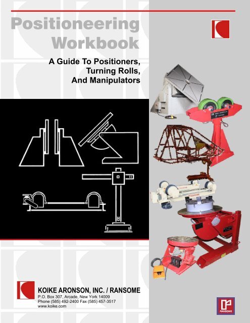
<strong>Positioneering</strong><br />
<strong>Workbook</strong><br />
A Guide To Positioners,<br />
Turning Rolls,<br />
And Manipulators<br />
KOIKE ARONSON, INC. / RANSOME<br />
P.O. Box 307, Arcade, New York 14009<br />
Phone (585) 492-2400 Fax (585) 457-3517<br />
www.koike.com
Preface<br />
What’s This <strong>Workbook</strong> For:<br />
The <strong>Positioneering</strong> <strong>Workbook</strong> was conceived to compliment<br />
the Handbook of <strong>Positioneering</strong> for evaluating applications and<br />
selecting specific model Positioners. It’s the literature information,<br />
specification sheets, informal work sheets, and crib notes<br />
used for years in the industry condensed and organized for easy<br />
use. Although the <strong>Workbook</strong> was designed to compliment the<br />
Handbook of <strong>Positioneering</strong>, it’s function as a standalone model<br />
applications manual can not be discounted.<br />
Who’s This <strong>Workbook</strong> For:<br />
It makes no difference if you’re an expert or a novice, if<br />
you’re in engineering, manufacturing, purchasing, or sales, the<br />
<strong>Positioneering</strong> <strong>Workbook</strong> gives you a simple, logical checklist<br />
to successfully select the right positioning equipment for the<br />
right job.<br />
TABLE OF CONTENTS<br />
Preface<br />
Why Use a Positioner<br />
Abbreviated Terms<br />
Universal Balance Positioners<br />
Special Utility / B1&B3<br />
Worksheet<br />
Gear Driven Positioners<br />
Worksheet<br />
Gear Elevating Positioners<br />
Worksheet<br />
Headstock/Tailstock Positioners<br />
Worksheet<br />
Floor Turntables<br />
Worksheet<br />
Turning Rolls<br />
Worksheet<br />
Manipulators<br />
Worksheet<br />
2<br />
3<br />
7<br />
8<br />
10<br />
11<br />
12<br />
14<br />
16<br />
17<br />
18<br />
22<br />
23<br />
24<br />
25<br />
27<br />
28<br />
30<br />
3
Why Use a Positioner<br />
You should use a positioner because welds made in the flat<br />
or slightly downhand position are made faster, better, cheaper,<br />
and in many cases safer than out-of-position welds. Without the<br />
use of a positioner, welds made in the vertical or overhead position<br />
are commonly deposited at the relatively low rate of as little<br />
as 3 pounds per hour. When properly positioned deposition<br />
rates can easily exceed 10 pounds per hour, depending of<br />
course on the thickness and mass of the parts being welded. The<br />
use of automatic process equipment can eliminate the need for<br />
the operator to hold the arc further increasing productivity. Positioned<br />
welds look better and quality is more easily controlled requiring<br />
less operator skill and producing less fatigue. Of course,<br />
it is possible to make positioned welds without using a positioner.<br />
Small weldments can be clamped in a vise, large ones moved<br />
with a crane. But these simplified methods seldom allow the ideal<br />
position to be attained, and are much more time consuming and<br />
hazardous to employ. Probably the first step toward the production<br />
of low cost, efficient welded products lies in the design of the<br />
weldment. But the second step (even ahead of welding process<br />
selection) is USE A POSITIONER. Put your self (and your weldment)<br />
in a good position for increased profits.<br />
What does a positioner do?<br />
First, of course, it provides a means to place the weldment in<br />
the ideal position for downhand welding. But sometimes a positioner<br />
performs another important function: it provides the weld<br />
travel speed by securing a welding head in a fixed position and<br />
allowing the positioner to move the part. This eliminates the operator<br />
variable, and is another major step toward better welds.<br />
Positioners are manufactured in various styles and configurations<br />
to accommodate different weldments and procedures :<br />
Universal Balance<br />
The Universal Balance Positioner allows the weldment to be<br />
mounted so that it can be moved by hand about its own center of<br />
gravity. Universal Balance Positioners can also be equipped<br />
with powered faceplate rotation for powered circumferential<br />
welds. They range in load capacity from 25 to 4000 lbs.<br />
Special Utility<br />
This group includes various small Positioners including<br />
non-balanced bench mounted units and floor bench mounted<br />
units with powered faceplate rotation. Their application is similar<br />
to the Universal Balance, except that the load is not balanced<br />
about its center-of-gravity. They would be selected for<br />
smaller, lighter loads, usually under 500 lbs.<br />
Gear Driven Positioner<br />
This type provides powered rotation of a work-piece, and in<br />
addition gives powered gear driven control of the table tilt. The<br />
table can be tilted from horizontal, through vertical to 45 degrees<br />
past the vertical. This type is often called a “Flat - 135<br />
degree” Positioner. Powered table rotation is variable speed to<br />
permit making circumferential welds at any desired speeds.<br />
Gear driven positioners are offered from 1,000 lbs. to<br />
1,000,000 lbs. capacity. Various accessories extend the versatility<br />
of these units.<br />
Headstock/Tailstocks<br />
These units permit long work-pieces to be mounted between<br />
centers and turned. Headstocks permit a work-piece to<br />
be turned at controlled speed about a horizontal axis. When<br />
used with a Tailstock, the combination forms a welding lathe.<br />
Since a Headstock/Tailstock combination is normally not<br />
mounted in precision alignment like an engine lathe, it is important<br />
that the means used to mount the work-piece allow a small<br />
amount of “float” or angular misalignment.<br />
Floor Turntables<br />
The Floor Turntable Positioner allows a weldment to be<br />
rotated about the vertical axis just a few feet off the floor. Variable<br />
Speed powered rotation is standard.<br />
Turning Rolls<br />
This device provides rotation of long cylindrical workpieces<br />
such as tanks and cylinders for making circumferential<br />
welds.<br />
Manipulators<br />
Where a positioner positions the work-piece, a manipulator<br />
positions the welding head over the work-piece. It provides<br />
various combinations of lift (vertical motion of the head), reach<br />
(horizontal motion of the head), or kingpin rotation (rotation of<br />
the entire manipulator on vertical axis through the mast). The<br />
various motions are available either powered or manual, and<br />
powered versions may be fixed speed or variable.<br />
4
How do I select the right positioner for my job?<br />
Selection of the type of positioners depends upon the size<br />
and shape of the work-piece. The descriptions and specifications<br />
in this brochure, will assist in making this selection. Selection of<br />
the size or rating of the positioner depends upon the weight of<br />
the work-piece and also on the location of its center-of-gravity. If<br />
a work-piece is mounted on a gear driven positioner, directly over<br />
the rotation axis, the weight will act straight down and will exert<br />
no torque load on the tilt gearing, like this:<br />
If the work-piece is mounted with its CG off the rotation<br />
axis, and the table is other than horizontal, the rotation drive<br />
will have to exert a torque in order to lift the CG as the table<br />
rotates, like this:<br />
As the positioner is tilted, the weight of the work-piece exerts<br />
a turning moment around the tilt axis, like this:<br />
The positioner must be selected so that the rotation drive<br />
has adequate torque capacity to handle the load, which is<br />
equal to W x r. This is stated in the specifications by giving the<br />
rotation torque in lb-in of “W (Lbs.) x r” (off center). Multiply<br />
your work-piece weight in pounds time the eccentricity<br />
(distance from CG to rotation axis) to check this.<br />
As an example of the above, the HD20 has a 2000 lb. capacity<br />
if the CG is 6” above the surface of the table and 6” off<br />
center from the rotation axis.<br />
The tilt gearing and motor must withstand this turning moment<br />
which is equal to W x d. Information is provided in the<br />
specifications to enable the user to select the proper positioner<br />
depending upon the location of the center-of gravity. Ratings are<br />
given for a specified distance above the surface of the workplate,<br />
and is stated as W (Lbs.) @ d” (CG Overhang). A table in<br />
the Gear Driven section shows the tilt capacity of the gear driven<br />
positioner models at various CG distances.<br />
5
Other Factors to Consider<br />
Swing Clearance<br />
When selecting a positioner, don’t forget to leave clearance to<br />
swing the work above the floor when the table is in the full tilt<br />
position. This is a common error in specifying positioners. A rotating<br />
weldment obviously will have trouble trying to penetrate a<br />
concrete floor. But <strong>Koike</strong> Aronson has simple solutions for large<br />
work pieces. Aronson positioners are available with either manually<br />
adjustable bases, or powered Elevating bases which adjust<br />
the table height for larger work. Fixed based machines also can<br />
be elevated by using a riser or sub-base. When we know what<br />
you expect to position, we can help you decide which base is<br />
best.<br />
Calculating Surface Speed<br />
Positioner motions are rated in revolutions-per-minute (rpm) for<br />
both tilt and rotation. To weld at a desired inch per- minute (ipm)<br />
(mm/s) rate, you must convert from ipm (mm/s) to rpm to select<br />
the positioner drive speed you need. There is a very simple formula<br />
you can use to do that. It’s I=RC. The “I” in the formula<br />
stands for ipm (mm/s) surface speed. The “R” is rpm and the “C”<br />
is work-piece circumference in inches (millimeters). When you<br />
use the formula, make sure that all units are the same for I and<br />
C. Don’t mix up inches, feet, and millimeters in one calculation.<br />
Revolutions-per-minute, of course, do not change with the measurement<br />
system selected. Suppose that you want to weld a 60 in<br />
(1520mm) diameter work-piece at 12 ipm (5mm/s) surface<br />
speed. How many rpm do you need? First, determine the circumference<br />
for a 60 in (1520mm) diameter work-piece. It is 60 in x π<br />
( or 3.1416), which equals a 188.5 in (4790mm) circumference.<br />
Second, divide the desired 12 ipm (300mm/s) surface speed by<br />
the work-piece circumference. The result is 0.001 rps or 0.064<br />
rpm. That means that the table must turn 0.001 revolution per<br />
second, 0.064 revolutions in one minute, or 3.84 revolutions per<br />
hour. An easy way to remember the formula is to find whatever<br />
unknown quantity you need when the other two are known by<br />
using this diagram.<br />
Cover the quantity on the diagram (either, I, R, or C)<br />
with your finger and perform the remaining calculation. For<br />
example, to find R (rpm), cover up the R. You then see the<br />
I (ipm) must be divided by C (circumference). Depending on<br />
how large a diameter (slow rpm) and how small a diameter<br />
(fast rpm) you need to weld, the positioner’s speed range<br />
should be selected accordingly. In most instances, the standard<br />
speed ranges will be adequate. Optional speed ranges<br />
are available.<br />
Speed Regulation<br />
When using a positioner to turn an unbalanced (eccentric)<br />
load, the load moment imposed on the positioner will vary.<br />
Consider the problem of welding an elbow to a straight piece of<br />
pipe held by the positioner. The welding must be done at a<br />
constant surface speed, even though the elbow exerts varying<br />
forces throughout rotation.<br />
<strong>Koike</strong> Aronson Ransome Positioners use Variable frequency<br />
drives and motors with dynamic braking to provide a constant<br />
speed throughout rotation. Sensor-less flux vector drive are<br />
used standard on most Positioners with optional full flux vector<br />
drives available. Additional braking resistors may be used for<br />
larger loads and highly eccentric situations.<br />
Turning Rolls<br />
Selection of turning rolls is based on two factors: the load<br />
carrying capacity of the wheels, and the turning capacity of the<br />
drive. Both are listed in the specifications. Turning capacity<br />
becomes significant only if the load is eccentric, and then the<br />
considerations apply as an eccentric load on a positioner. The<br />
eccentric load in Ib-in divided by the diameter of the vessel in<br />
inches must not exceed the Tractive Pull listed in the specifications.<br />
6
Other Factors to Consider<br />
Practical Center of Gravity as it Effects Gear Driven Positioners<br />
1. The CG of a weldment is usually near the center of the weldment.<br />
2. The CG of a weldment is exactly in the center of asymmetrical<br />
weldment.<br />
3. “A” is a symmetrical weldment: There is no top or bottom, just<br />
two ends and two sides of 1” steel plate. Each end is 1x12x12<br />
and weighs 40.8#. Each side is1x12x34, weighs 115.6#. 115.6#<br />
x 2, plus 40.8# x 2 equals 312.8#. (Steel weighs approximately<br />
.283pounds/cubic inch.) If one end is secured to the<br />
table of a Gear Driven Positioner, the CG will be 18” out from or<br />
above the table. If either side, or the open top or bottom is secured<br />
to the table, the CG will be 6” above it.<br />
4. “B” is also a symmetrical weldment: A 2” plate rib has been<br />
added in the middle, making the weldment a stiff column. The<br />
2x10x34 steel rib weighs 192.7# so the weldment now weighs<br />
505.5#. The rib being right in the middle added weight equally<br />
in opposite directions from center, so the CG is still in dead<br />
center.<br />
5. “C” is an un-symmetrical weldment: We want a box instead of a<br />
column, so we add a 2” thick bottom to weldment “A”. 2x12x36<br />
steel weighs 244.6# so total weight is now 557.6#. But the CG<br />
will not be at 7”, halfway from top or bottom, because we added<br />
nothing to the top to balance the weight of the bottom. We<br />
made no change at either end, and the bottom is as much left<br />
as right, so the CG remains 18” in from either end.<br />
6. The CG always moves toward any part that is added to a symmetrical<br />
weldment. Locating the CG is a function of moments.<br />
“Moment” means force or tendency to produce motion. A Moment<br />
is weight multiplied by length (Arm). Like a lever. And like<br />
a lever, we must have a hinge point, a reference plane. The top<br />
surface of a Gear Driven Positioner’s table is our reference<br />
plane. Load Capacity Tables give ratings for various distances<br />
the CG is above the table, so this is very handy. Whenever possible,<br />
weldments should be mounted with the heavy side next to<br />
the table, so let’s figure it that way.<br />
7. Each separate symmetrical part will have a known weight and<br />
CG, and the CG will be a known distance from the table top<br />
surface. Multiplying weight by distance (arm) gives the poundinch<br />
(lb-in) moment of the part. Adding all the moments and<br />
dividing by total weight gives the location of the CG of the weldment.<br />
7<br />
We don’t need to take each end and each side separately<br />
because the side and ends make symmetrical mass weighing<br />
312.8#, with the CG in the center of that mass. With the 2" plate<br />
between it and the table, the CG will be 8" above the table.<br />
312.8# x 8" =2502.41b-in.<br />
The 244.8# bottom’s CG is 1" above the table.<br />
244.8# x l" = 244 Ib-in.<br />
Adding 244.8 Ib-in and 2502.4 Ib-in equals 2747.2 lb-in Total<br />
Moment. Dividing 2747.2 lb-in Total Moment by557.6 Total<br />
Weight locates the CG 4.9” above table top surface.<br />
Weldment “A”<br />
Weldment “B”<br />
Weldment “C”
Universal Balance Positioner<br />
(1) First find the Center of Gravity of Rotation<br />
When a work-piece is placed on the worktable of an Aronson<br />
Positioner with its center of gravity located on the worktable rotational<br />
axis, it will be balanced on that axis. It will, therefore, be very<br />
easy to rotate on that axis, even if it is ten times heavier than the<br />
operator. In fact, it rotates so easily that a friction band had to be<br />
fitted to the worktable of the Positioner to provide a drag effect and<br />
to enable the operator to place and stop the work-piece wherever<br />
he wants. It is very easy to find the center of gravity of two dimensions,<br />
but all work-pieces have three dimensions, and all weldments<br />
require movement in two opposing axes, to obtain all possible positions.<br />
(2) Balance is achieved by adjusting the worm gear so that the<br />
tilt axis intersects and the center of gravity located on the rotation<br />
axis.<br />
The Worktable is at one end of the Arm and a worm and worm<br />
gear segment are at the other end. The Arm and the Gear Box are<br />
integral. A Shaft at the extreme end of the gear box rotates in Tapered<br />
Roller Bearings, in a barrel shaped housing. A simple adjustment<br />
of the worm by the operator will change the angle of the arm,<br />
allowing the tilt axis of the arm to intersect the center of gravity of<br />
the work-piece in the third dimension. With both axes intersecting<br />
the center of gravity of the work-piece, it can be pushed or pulled by<br />
your hand and simply put wherever you want it. . . effortlessly. . .<br />
because it is in balance. This is the principle of the <strong>Koike</strong> Aronson<br />
Universal Balance Positioner.<br />
(3) Determining Load Capacity Universal Balance positioners<br />
are rated for overhanging loads from the table surface.<br />
A typical rating is “1000 lb at 12 in. (453 kg at 300 mm) CG<br />
height.” That means that the work-piece can weigh as much as<br />
1000 lb (453 kg) when its CG overhang does not exceed 12 in.<br />
(300 mm) from the table surface.<br />
In the drawing below, a CG symbol is shown with a dimension<br />
of 13 in. (330 mm) above the centerline of the work arm. This<br />
indicates the maximum CG height that can still be intersected by<br />
the tilt axis within the 30°angle adjustment range.<br />
Since the distance from the table top to the centerline of the<br />
work arm is 3.625 in. (92 mm), the CG axis for balancing purposes<br />
can only be 9.375 in. (238 mm) above the table top. Any<br />
greater distance indicates the need for counterweights.<br />
Don’t confuse the two separate CG considerations for Universal<br />
Balance positioners. One specification tells what load fits the<br />
weight rating of the positioner. The CG shown in the sketch<br />
shows the maximum CG height that can be intersected by the tilt<br />
axis for a given model.<br />
8
Universal Balance Specifications<br />
SPECIFICATIONS C25 C100 C1000 C2000 C4000<br />
Maximum Load 25 Lbs. 100 Lbs. 1,000 Lbs. 2,000 Lbs. 4,000 Lbs.<br />
DIM A, Overhang, 6-1/2” 11” 32” 35” 51-1/2”<br />
DIM B, Max. CG Height 3” 4-3/4” 14-1/2” 16” 33-1/2”<br />
DIM C, Max. Part Diameter 14” 20” 66” 75” 96”<br />
DIM D, Max. Part Length 16” 24” 100” 100” 96”<br />
DIM E, Table Diameter 1-1/2” 5” 8” 8” 12”<br />
DIM F, Hole Size 10-32 1/4” Slots 17/32” 17/32” 1-1/32”<br />
DIM G, Bolt Circle 1-1/4” 4 Slots 5” 5” 8”<br />
DIM H, Table Thickness 1/4” 1/4” 15/16” 1” 1-1/2”<br />
DIM I, Pilot Hole 10-32 1/4-20 1/2-13 3/4-10 1”-8 x 1.25<br />
DIM J, Height Range 6-1/4” Fix 5” Fix 27”- 37” 30”- 36” 41-1/2” Fix<br />
DIM K, Table to Tilt Axis 7/8” 2” 3-5/8” 3-1/8” 6”<br />
DIM L, Rear Overhang 1-1/2” 2-1/8” 4-3/4” 8” 1”<br />
DIM M, Base Overall Width 6” 4-1/2” 43” 43” 58”<br />
DIM N, Base Overall Length. 9” 4-1/2” 37-3/4” 48” 78”<br />
DIM O, Anchor Hole Size 9/32” (4) 13/32” (4) 9/16” (4) 9/16” (6) 13/16” (8)<br />
DIM P, Anchor Hole Width Centers 5-1/4” 3-3/4” 40” 40” 55”<br />
DIM Q, Anchor Hole Length Centers 8-1/4” 3-3/4” 33” 39” -<br />
DIM R, Wrench Size 1/4” 1/2” 1” 1” 2-1/4”<br />
Type of Base Plate Plate “T” “T” “T”<br />
Tilt Axis Brake Yes No Yes Yes Yes<br />
Tilt Axis Pinlock No No Yes Yes Yes<br />
Rotation Axis Brake Yes No Yes Yes Yes<br />
Rotation Axis Pinlock No Yes Yes Yes Yes<br />
Bearing type Ball Tapered Tapered Tapered Tapered<br />
Ground Current Conduction N/R 300 Amps 800 Amps 1200 Amps 2000 Amps<br />
Power Axis Available No No 9<br />
Yes Yes Yes<br />
Shipping Weight 15 Lbs. 30 Lbs. 340 Lbs. 500 Lbs. 1,300 Lbs.
Special Utility B1/B3 Positioners<br />
Keep little things from becoming big problems.<br />
Scale down everything and put it on a work bench. That will<br />
give you some idea of what we have for bench welding light duty<br />
machining, inspection, wiring and assembly. Or mount it on casters<br />
and roll it around. If it’s in the 50 to 500 lb. capacity range, we<br />
have a model for the application. Some of our models are no<br />
more complicated than a rotating vise. Others may be small, but<br />
very sophisticated. Take one of our bench-mounted, powered<br />
positioners for example. It has rotation, tilt, drive, and an enclosed<br />
motor with special lubricants. It’s used in controlledatmosphere<br />
chambers for welding titanium, zirconium, and hafnium.<br />
We sell a large variety of special accessory items. Examples<br />
are speed indicators that read in both rpm’s and ipm’s. We<br />
have self-centering welding chucks for work of various diameters.<br />
For the large number of configurations and capacities available,<br />
refer to the individual series literature.<br />
10
Worksheet - Special Utility, B1/B3<br />
1. TOTAL LOAD WEIGHT Lbs. (Including Fixture)<br />
2. PIECE PART DIMENSIONS:<br />
LENGTH<br />
WIDTH<br />
HEIGHT<br />
Inches<br />
Inches<br />
Inches (Above Table)<br />
MAXIMUM SWING CLEARANCE/RADIUS<br />
Inches<br />
3. OVERHANG C/G Inches<br />
(Distance the center of gravity of the load is from the surface of the table)<br />
4. OFF-CENTER C/G Inches<br />
(Distance the center of gravity of the load is from the center of rotation)<br />
5. ROTATION AXIS: MANUAL POWERED, Variable Speed<br />
6. TILT AXIS: MANUAL POWERED, Constant Speed<br />
7. TABLE:<br />
ROUND<br />
SQUARE<br />
Inches Diameter (Standard)<br />
Inches Square<br />
8. PRIMARY POWER: Volts, Phase, Hertz<br />
(Standard: 115/1/60)<br />
9. ACCESSORIES:<br />
10. NOTES:<br />
11
Gear Driven Positioners<br />
HOW TO SELECT AGEAR DRIVEN POSITIONER TO BEST<br />
MEET YOUR NEEDS<br />
The illustration below shows a typical capacity plate that we<br />
attach to each Aronson Gear Driven Positioner. This happens to<br />
be the capacity plate for a Model HD400 Aronson Gear Driven<br />
unit. An HD400 is designed to handle loads up to 40,000 lbs<br />
(18,140kg) with a CG at a distance from the surface of the table<br />
of 12” (300mm). All the information required for loading the positioner<br />
is either on the capacity plate, or it can be simply calculated<br />
from the data on the plate.<br />
Rotation Torque Load:<br />
To find your weldments’ Rotation Torque Load, multiply the<br />
weldment weight in Pounds by the distance in inches that Center-of-Gravity<br />
(CG) will be from the center of the table. This<br />
measurement is taken parallel to the table surface. Do not exceed<br />
the maximum load torque shown in the “rotation” column.<br />
Tilt Torque Load:<br />
To find your weldments’ Tilt Torque Load, add the Inherent<br />
Overhang (Inches) to the distance (Inches) the weldments’ CG is<br />
from the table top surface. This is measured perpendicular to the<br />
table top surface. Then multiply this total distance in Inches by<br />
the weight of the weldment. Do not exceed the maximum load<br />
torque shown in the “tilt” column on next page.<br />
How About Swing Clearance:<br />
When selecting a positioner, don’t forget to leave clearance<br />
to swing the work above the floor when the table is in the<br />
full tilt position. This is a common error in specifying positioners.<br />
For excessive work-pieces, Aronson positioners are available<br />
with manually adjustable bases, or powered Elevating<br />
bases which adjust the table height for larger work. Fixed-base<br />
machines also can be elevated by using a riser or sub-base.<br />
12
Comprehensive Load Capacity Table<br />
Model<br />
Available Rotation<br />
G Model Torque<br />
In/Lbs.<br />
Tilt Torque<br />
In/Lbs.<br />
INH<br />
O.H.<br />
inches<br />
CG<br />
@<br />
6”<br />
CG@<br />
12”<br />
CG@<br />
18”<br />
CG@<br />
24”<br />
CG@<br />
30”<br />
CG@<br />
36”<br />
CG@<br />
42”<br />
CG@<br />
48”<br />
CG@<br />
54”<br />
CG@<br />
60”<br />
CG@<br />
66”<br />
CG@<br />
72”<br />
10P — 6,000 10,500 4.5 1,000 635 466 365 — — — — — — — —<br />
HD20 — 12,000 21,000 4.5 2,000 930 730 600 520 450 400 360 325 — — —<br />
HD25 — 15,000 31,875 6.8 2,500 1,700 1,285 1,035 875 750 650 580 520 470 430 400<br />
HD30 — 36,000 56,250 6.8 — 3,000 2,270 1,830 1,530 1,300 1,100 1,000 900 830 760 700<br />
HD45 — 54,000 84,375 6.8 — 4,500 3,400 2,750 2,300 1,975 1,720 1,530 1,380 1,250 1,150 1,100<br />
HD60 — 72,000 123,000 8.5 — 6,000 4,650 3,790 3,200 2,750 2,400 2,200 1,900 1,700 1,600 1,500<br />
HD100 — 120,000 205,000 8.5 — 10,000 7,700 6,300 5,300 4,600 4,000 3,600 3,200 3,000 2,700 2,500<br />
HD160 — 192,000 336,000 9.0 — 16,000 12,400 10,000 8,600 7,400 6,600 5,900 5,300 4,800 4,400 4,000<br />
HD240 — 288,000 504,000 9.0 — 24,000 18,500 15,000 13,000 11,000 9,800 8,800 8,000 7,300 6,700 6,200<br />
HD400 G400 480,000 840,000 9.0 — 40,000 31,000 25,000 21,500 18,500 16,400 14,600 13,200 12,000 11,000 10,200<br />
HD500 G500 600,000 1,050,000 8.8 — 50,000 39,000 32,000 27,000 23,400 20,600 18,500 16,700 15,200 14,000 13,000<br />
HD600 G600 720,000 1,260,000 9.0 — 60,000 46,500 38,000 32,000 28,000 24,500 22,000 20,000 18,000 16,500 15,500<br />
HD700 G700 840,000 1,470,000 9.0 — 70,000 54,500 44,500 37,500 32,500 28,500 25,500 23,000 21,000 19,500 18,000<br />
G850 1,020,000 1,800,000 9.0 — 85,000 66,600 54,500 48,000 42,000 37,000 32,000 29,000 26,000 24,000 22,000<br />
G1200 1,440,000 2,880,000 12.0 — 120,000 96,000 80,000 68,600 60,000 53,400 48,000 43,600 40,000 37,000 34,200<br />
G2200 2,640,000 5,400,000 12.5 — 220,000 177,000 148,000 127,000 111,000 100,000 89,000 81,000 74,000 69,000 64,000<br />
G3500 4,200,000 9,300,000 14.5 — 350,000 286,000 240,000 210,000 184,000 160,000 145,000 135,000 125,000 115,000 107,000<br />
G7000 5,000,000 18,600,000 14.5 — 700,000 570,000 480,000 420,000 368,000 320,000 290,000 270,000 250,000 230,000 214,000<br />
G10000 12,000,000 30,000,000 18.0 — 1,000,000 890,000 760,000 665,000 590,000 540,000 485,000 440,000 410,000 380,000 335,000<br />
Models and specifications subject to change without notice.<br />
For models greater than 1,000,000 Lbs. capacity, please consult Factory<br />
13
Worksheet- Gear Driven Positioners<br />
1. TOTAL LOAD WEIGHT Lbs. (Including Fixture)<br />
2. PIECE PART DIMENSIONS:<br />
LENGTH<br />
WIDTH<br />
HEIGHT<br />
Inches<br />
Inches<br />
Inches (Above Table)<br />
MAXIMUM SWING CLEARANCE/RADIUS<br />
Inches<br />
3. OVERHANG C/G Inches<br />
(Distance the center of gravity of the load is from the surface of the table)<br />
4. OFF-CENTER C/G Inches<br />
(Distance the center of gravity of the load is from the center of rotation)<br />
5. ROTATION AXIS: POWERED, Variable Speed SPECIAL RPM REQUIRED RPM<br />
6. TILT AXIS: POWERED, Constant Speed SPECIAL RPM REQUIRED RPM<br />
7. TABLE:<br />
ROUND<br />
SQUARE<br />
Inches Diameter (Standard on Ransome Model)<br />
Inches Square (Standard on Aronson Model)<br />
MACHINED SURFACE (optional)<br />
8. PRIMARY POWER: Volts, Phase, Hertz<br />
(Most Standard At: 430/3/60)<br />
9. ACCESSORIES:<br />
10. NOTES:<br />
11. MODEL (if known):<br />
14
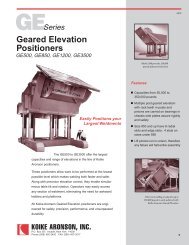
Elevating Positioners<br />
The sketch shows three different welds made on a spoolshaped<br />
work-piece by one <strong>Koike</strong> Aronson Geared Elevation<br />
Positioner. In the first step (A), the table rotates as a girth weld is<br />
completed at a constant operator height. Then in (B) the operator<br />
tilts the table up 45 degrees and completes a fillet weld on the<br />
rotating table at a specific height. In Step (C) the Positioner’s<br />
height is increased, then the table is tilted down to the 135 degree<br />
position and a final fillet weld is added while the table rotates.<br />
Due to low working heights, makeshift operator platforms<br />
are eliminated, creating much safer working conditions.<br />
<strong>Koike</strong> Aronson / Ransome Elevating Positioners are available<br />
in both Multiple post / Rack and pinion lift and ball screw<br />
elevation design. Both tilt, and rotational torque requirements<br />
are calculated in the same manner as Gear Driven Positioners<br />
(page 12). The elevation stroke should be derived from the<br />
required swing radius (diameter) that the work piece requires.<br />
Elevation components for both models are sized by the factory<br />
to correspond with the required load/size Elevating Positioner<br />
selected.<br />
Step “A”<br />
Step “B”<br />
GE500VF, Rack and Pinion Elevation<br />
rated at 50,000 Lbs. Capacity<br />
Step “C”<br />
15<br />
250PE, Screw Jack Elevation<br />
rated at 25,000 Lbs
Comprehensive Load Capacity Table<br />
This comprehensive capacity chart provides the necessary information you need to select Aronson Geared Elevation<br />
Positioners. You should select the Positioner model based on the greatest torque requirement, either rotation or tilt torque.<br />
Model<br />
Rotation<br />
Torque<br />
In/Lbs.<br />
Tilt Torque<br />
In/Lbs.<br />
INH<br />
O.H.<br />
inches<br />
CG<br />
@<br />
6”<br />
CG@<br />
12”<br />
CG@<br />
18”<br />
CG@<br />
24”<br />
CG@<br />
30”<br />
CG@<br />
36”<br />
CG@<br />
42”<br />
CG@<br />
48”<br />
CG@<br />
54”<br />
CG@<br />
60”<br />
CG@<br />
66”<br />
CG@<br />
72”<br />
GE25 15,000 27,500 5.0 2,500 1,600 1,200 950 780 670 580 520 460 420 380 350<br />
GE30 36,000 60,750 8.2 — 3,000 2,300 1,880 1,600 1,375 1,200 1,075 975 890 820 750<br />
GE45 54,000 91,125 8.2 — 4,500 3,500 2,800 2,400 2,050 1,800 1,600 1,450 1,300 1,200 1,100<br />
GE60 72,000 123,000 8.5 — 6,000 4,650 3,790 3,200 2,750 2,400 2,200 1,900 1,700 1,600 1,500<br />
GE90 108,000 184,500 8.5 — 9,000 7,000 5,700 4,800 4,150 3,650 3,250 2,950 2,700 2,480 2,300<br />
GE120 144,000 252,000 9.0 — 12,000 9,300 7,600 6,450 5,600 4,950 4,400 4,000 3,650 3,350 3,100<br />
GE180 216,000 369,000 8.5 — 18,000 13,900 11,350 9,600 8,300 7,300 6,500 5,900 5,400 4,950 4,600<br />
GE250 300,000 512,500 8.5 — 25,000 19,400 15,800 13,300 11,500 10,200 9,000 8,200 7,500 6,900 6,400<br />
GE500 600,000 1,050,000 8.8 — 50,000 39,000 32,000 27,000 23,400 20,600 18,500 16,700 15,200 14,000 13,000<br />
GE850 1,020,000 1,800,000 9.0 — 85,000 66,600 54,500 48,000 42,000 37,000 32,000 29,000 26,000 24,000 22,000<br />
GE1200 1,440,000 2,880,000 12.0 — 120,000 96,000 80,000 68,600 60,000 53,400 48,000 43,600 40,000 37,000 34,200<br />
GE3500 2,640,000 9,300,000 14.5 — 350,000 286,000 240,000 210,000 184,000 160,000 145,000 135,000 125,000 115,000 107,000<br />
Models and specifications subject to change without notice.<br />
For models greater than 350,000 Lbs. capacity, please consult Factory<br />
16
Worksheet- Elevating Positioners<br />
1. TOTAL LOAD WEIGHT Lbs. (Including Fixture)<br />
2. PIECE PART DIMENSIONS:<br />
LENGTH<br />
WIDTH<br />
HEIGHT<br />
Inches<br />
Inches<br />
Inches (Above Table)<br />
MAXIMUM SWING CLEARANCE/RADIUS<br />
Inches<br />
3. OVERHANG C/G Inches<br />
(Distance the center of gravity of the load is from the surface of the table)<br />
4. OFF-CENTER C/G Inches<br />
(Distance the center of gravity of the load is from the center of rotation)<br />
5. ROTATION AXIS: POWERED, Variable Speed SPECIAL RPM REQUIRED RPM<br />
6. TILT AXIS: POWERED, Constant Speed SPECIAL RPM REQUIRED RPM<br />
7. ELEVATION AXIS: (only specify if there is a preference)<br />
8. TABLE:<br />
GEAR RACK (Aronson Style)<br />
BALL SCREW (Ransome Style)<br />
ROUND<br />
SQUARE<br />
Inches (Standard on Ransome models)<br />
Inches (Standard on Aronson models)<br />
MACHINED SURFACE (optional)<br />
9. PRIMARY POWER: Volts, Phase, Hertz<br />
10. ACCESSORIES:<br />
11. NOTES:<br />
12. MODEL (if known):<br />
17
Headstock/Tailstock Positioners<br />
The quality features <strong>Koike</strong> Aronson builds into their headstock/tailstock<br />
positioners assures safety, precision and long machine<br />
life.<br />
Head and Tailstock Positioners can help you:<br />
¨ Make high quality “positioned” welds while reducing production<br />
and handling costs. * Long fabrications, elliptical<br />
vessels, railroad and truck frames can be positioned<br />
easily.<br />
¨ Model selections handle 2500 Ib to 240,000 Ib weldments.<br />
Optional accessories allow application versatility.<br />
Headstock/Tailstock Features<br />
1. Boxed section table designs on many models have<br />
more strength than solid plate tables and less deflection.<br />
Various sizes available, round or square.<br />
2. Precision pilot holes facilitate centering loads and fixturing.<br />
Thru-Hole (hollow) spindles can be supplied for<br />
preheat and purge piping.<br />
3. Full clamping length table slots have nut access holes<br />
in back. Slots are self-cleaning.<br />
4. Grounding blocks for positive clamping of ground cable<br />
terminals to assure continuous, non-varying weld circuit<br />
conduction. Optional Sliding copper ground shoes are<br />
also available.<br />
5. Steel and all-welded construction give utmost strength.<br />
Boxed section design has maximum rigidity without excessive<br />
weight.<br />
6. NEMA12 dust-tight enclosures protect the motor controls<br />
from contamination. Disconnect switches Variable Frequency<br />
drives assure reliable and safe operation.<br />
7. Dust and oil-tight pendants with safety control circuits<br />
allow remote operation of tables, even when wearing heavy<br />
welding gloves.<br />
8. Brakes motors assist in holding position. Motors are protected<br />
inside of chassis.<br />
9. Worm-gear drive reductions, lifetime lubricated, control<br />
maximum loads, precisely and safely. Welded steel gear cases<br />
won’t break or shift under load.<br />
10. Anti-friction tapered roller bearings of high capacity on<br />
spindles are preloaded for maintenance-free weld ground conduction.<br />
11. Heavy duty precision final drive gearing for smooth<br />
rotation and minimum lost motion of table is guarded for life.<br />
18
Selecting Headstock/Tailstock Positioners<br />
How to Select a Headstock/Tailstock To Best Meet Your<br />
Needs:<br />
Head and tail units are rated for overhanging loads. Determine<br />
the weight and how far ahead of the table the CG (Centerof-Gravity)<br />
of the work-piece will be located, then select the<br />
proper model from the chart on page 21.<br />
When head and tail units are used together, the load weight<br />
is shared by both units. As explained below, the weight is imposed<br />
on the flexible point of the clamping fixtures. The distance<br />
that the flexible point is ahead of the table determines the overhanging<br />
load on the head and tail units. This load can be compared<br />
to the chart on page 21, using the CG rating that corresponds<br />
to the flexible point’s distance away from the table.<br />
The headstock must also assure adequate rotational torque.<br />
Determine the distance that the load’s CG will be from the rotation<br />
axis, then multiple this distance in inches by the pounds of<br />
load weight to find “LBS- IN” of torque requirement. The chart on<br />
page 21 gives these ratings. For example, a 60,000 lb load with<br />
the CG at 6”off-center will require 360,000 Lb-In of torque. The<br />
Tailstocks with freewheeling tables do not need torque ratings.<br />
Importance of “Universal-Joint” attachment to weldment<br />
to Headstock & Tailstock<br />
A. Rigid Mounting.<br />
To be avoided- When rotating inaccurate work-pieces rigidly<br />
mounted between head and tail units that might be misaligned,<br />
great stresses are created that can tear the work from the table,<br />
or damage the work and positioners. Even if everything holds,<br />
rotation drag is created which could stall the headstock. A flexible<br />
connection between the load and tables to relieve misalignment<br />
is highly recommended.<br />
B. Pilot Mounting.<br />
A stub-shaft attached to each end of the work-piece and then<br />
engaged loosely into hollow table-receptacles will relieve misalignment.<br />
The stub-shafts also take the shear load of the work.<br />
This approach requires that the tail stock be movable on wheels<br />
and track to allow engagement of the stub-shafts during set-up.<br />
To impart rotation, drive dogs must be used at each end.<br />
C. Universal Pin Mounting.<br />
Loose pins through clevis-type connections provide flexibility<br />
and setup without having to move the tailstock. The load weight<br />
on the head and tail units is imposed on the pins, at a distance<br />
ahead of the table. Always keep the flexible point as near to the<br />
table as possible. Pilot mounting (sketch B) is ideal from this<br />
standpoint. Drive dogs for rotation are needed to save the pins<br />
19<br />
from heavy torsional loading.<br />
D. Wobble Plate Mounting.<br />
Four round drive dogs extend through holes in each wobble<br />
plate and carry the load, as well as impart rotation. Caps on<br />
end of drive dogs insure wobble plates do not slide off work<br />
piece, part or fixture.
Elevating Headstock/Tailstock Positioners<br />
Powered Elevation keeps work close to floor for each loading, adjusts to convenient welding height and lift full<br />
load for swing clearance height, safely.<br />
ARONSON STYLE PATENTED “GEARED ELEVATION”<br />
HEADSTOCK/TAILSTOCK POSITIONERS<br />
Geared Elevation has posts with rack teeth and chassis with lift<br />
pinions. All pinions are geared together and must run together.<br />
The chassis is always level and steady. With loading down on<br />
the front racks and a lesser reactionary force up on the rear<br />
racks it is impossible for all the teeth to wear out and fail<br />
simultaneously, regardless of length of service or magnitude of<br />
the load. If the heavier loaded front teeth wear out or break, the<br />
chassis will jam and will not crash down as the strong teeth at<br />
the rear are holding safely.<br />
RANSOME STYLE “BALL SCREW ELEVATION”<br />
HEADSTOCK/TAILSTOCK POSITIONERS<br />
The “Ball Screw” Elevation design makes maximum use of<br />
proven commercially available components, both in the<br />
elevation and guidance systems.<br />
Elevation is by means of commercial Ball screw jacks for<br />
high duty cycle operation, driven by a worm/wormgear<br />
arrangement. Elevation uses two of these screw jacks for<br />
redundancy, coupled together and driven by a common motor.<br />
Guidance is by means of wide, large diameter cam<br />
followers bearing on flat guide-ways, or Linear Bearings and<br />
ways depending on size. Guidance is provided on front and<br />
back of two columns that rigidly support the cantilevered load.<br />
In the case of Headstock / Tailstock Elevating Positioners,<br />
the synchronization between Head and Tailstock utilizes AC<br />
Variable Frequency drives that provide dynamic<br />
synchronization during the elevation cycle, as well as absolute<br />
mechanical resynchronization at full stroke, at either top or<br />
bottom limits. Periodic mechanical resynchronization at end of<br />
travel may be required.<br />
20
Comprehensive Load Capacity Table<br />
Elevating Headstock/Tailstock Positioners<br />
Model<br />
Load off<br />
Rotation CG<br />
Lbs. @ 6”<br />
Rotation<br />
Torque<br />
In/Lbs.<br />
Max Load<br />
Between Head<br />
& Tail (Lbs.)<br />
CG@<br />
6”<br />
CG@<br />
12”<br />
HS2VF 2,500 30,000 — 2,500 2,500 1,100 850 700 600 500 450 400 350 325 300<br />
TS2 2,500 — — 2,500 2,500 1,100 850 700 600 500 450 400 350 325 300<br />
HTS5VF—GE 5,000 30,000 5,000<br />
2H/2T-PE 5,000 30,000 5,000<br />
3H/3.5T-PE 6,000 36,000 6,000<br />
HS4VF 4,500 54,000 — 4,500 4,500 2,000 1,550 1,300 1,100 950 800 750 650 600 550<br />
TSVF 4,500 — — 4,500 4,500 2,000 1,550 1,300 1,100 950 800 750 650 600 550<br />
HTS9VF—GE 9,000 54,000 9,000<br />
3.5H/3.5T-PE 9,000 54,000 9,000<br />
HS6VF 6,000 72,000 — 6,000 6,000 4,400 3,450 2,850 2,400 2,100 1,850 1,650 1,500 1,400 1,250<br />
TS6 6,000 — — 6,000 6,000 4,400 3,450 2,850 2,400 2,100 1,850 1,650 1,500 1,400 1,250<br />
HTS12VF—GE 12,000 72,000 12,000<br />
4H/4T-PE 12,000 72,000 12,000<br />
HS10VF 10,000 120,000 — 10,000 10,000 7,350 5,850 4,850 4,100 3,600 3,200 2,850 2,600 2,350 2,200<br />
TS10 10,000 — — 10,000 10,000 7,350 5,850 4,850 4,100 3,600 3,200 2,850 2,600 2,350 2,200<br />
HTS20VF—GE 20,000 120,000 20,000<br />
5H/5T-PE 20,000 120,000 20,000<br />
HS16VF 16,000 192,000 — 16,000 16,000 12,000 9,600 8,000 6,850 6,000 5,300 4,800 4,350 4,000 3,850<br />
TS16 16,000 — — 16,000 16,000 12,000 9,600 8,000 6,850 6,000 5,300 4,800 4,350 4,000 3,850<br />
HTS32VF—GE 32,000 192,000 32,000<br />
6H/6T-PE 32,000 192,000 32,000<br />
HS20VF 20,000 240,000 — 20,000 20,000 15,000 12,000 10,000 8,550 7,500 6,650 6,000 5,450 5,000 4,600<br />
TS20VF 20,000 — — 20,000 20,000 15,000 12,000 10,000 8,550 7,500 6,650 6,000 5,450 5,000 4,600<br />
HTS20VF – GE 40,000 240,000 40,000<br />
HS25VF 25,000 300,000 — 25,000 25,000 18,900 15,200 12,750 10,950 9,600 8,550 7,700 7,000 6,400 5,950<br />
TS25 25,000 — — 25,000 25,000 18,900 15,200 12,750 10,950 9,600 8,550 7,700 7,000 6,400 5,950<br />
HTS50VF—GE 50,000 300,000 50,000<br />
7H/7T-PE 50,000 300,000 50,000<br />
HS30VF 30,000 400,000 — 30,000 30,000 22,850 18,450 15,500 13,350 12,200 10,450 9,400 8,550 7,850 7,250<br />
TS30 30,000 — — 30,000 30,000 22,850 18,450 15,500 13,350 12,200 10,450 9,400 8,550 7,850 7,250<br />
HTS60VF—GE 60,000 400,000 60,000<br />
8H/8T-PE 80,000 480,000 80,000<br />
HS45VF 45,000 540,000 — 45,000 45,000 34,400 27,850 23,400 20,150 17,700 15,800 14,250 13,000 11,900 11,000<br />
TS45 45,000 — — 45,000 45,000 34,400 27,850 23,400 20,150 17,700 15,800 14,250 13,000 11,900 11,000<br />
HTS90VF—GE 90,000 540,000 90,000<br />
10H/10T-PE 100,000 600,000 100,000<br />
HS80 80,000 960,000 — 80,000 80,000 61,150 49,500 41,600 35,850 31,500 28,100 25,350 23,100 21,200 19,600<br />
TS80 80,000 — — 80,000 80,000 61,150 49,500 41,600 35,850 31,500 28,100 25,350 23,100 21,200 19,600<br />
HTS160VF-GE 160,000 960,000 160,000<br />
16H/16T-PE 160,000 960,000 160,000<br />
HS120VF 120,000 1,440,000 — 120,000 120,000 92,000 75,000 83,000 54,000 48,000 42,000 38,000 35,000 32,000 30,000<br />
TS120 120,000 — — 120,000 120,000 92,000 75,000 83,000 54,000 48,000 42,000 38,000 35,000 32,000 30,000<br />
HTS240VF-GE 240,000 1,440,000 240,000<br />
21<br />
CG@<br />
18”<br />
CG@<br />
24”<br />
CG@<br />
30”<br />
CG@<br />
36”<br />
CG@<br />
42”<br />
CG@<br />
48”<br />
CG@<br />
54”<br />
CG@<br />
60”<br />
LOAD EVENLY DISTRIBUTED BETWEEN HEAD & TAILSTOCK<br />
LOAD EVENLY DISTRIBUTED BETWEEN HEAD & TAILSTOCK<br />
LOAD EVENLY DISTRIBUTED BETWEEN HEAD & TAILSTOCK<br />
LOAD EVENLY DISTRIBUTED BETWEEN HEAD & TAILSTOCK<br />
LOAD EVENLY DISTRIBUTED BETWEEN HEAD & TAILSTOCK<br />
LOAD EVENLY DISTRIBUTED BETWEEN HEAD & TAILSTOCK<br />
LOAD EVENLY DISTRIBUTED BETWEEN HEAD & TAILSTOCK<br />
LOAD EVENLY DISTRIBUTED BETWEEN HEAD & TAILSTOCK<br />
LOAD EVENLY DISTRIBUTED BETWEEN HEAD & TAILSTOCK<br />
LOAD EVENLY DISTRIBUTED BETWEEN HEAD & TAILSTOCK<br />
LOAD EVENLY DISTRIBUTED BETWEEN HEAD & TAILSTOCK<br />
LOAD EVENLY DISTRIBUTED BETWEEN HEAD & TAILSTOCK<br />
LOAD EVENLY DISTRIBUTED BETWEEN HEAD & TAILSTOCK<br />
LOAD EVENLY DISTRIBUTED BETWEEN HEAD & TAILSTOCK<br />
CG@<br />
66”<br />
CG<br />
@<br />
72”
Worksheet- Head/Tailstock Positioners<br />
1. TOTAL LOAD WEIGHT Lbs. (Including Fixture)<br />
2. PIECE PART DIMENSIONS:<br />
LENGTH:<br />
WIDTH:<br />
HEIGHT:<br />
Inches<br />
Inches<br />
Inches (Above Table)<br />
MAXIMUM SWING CLEARANCE/RADIUS<br />
3. OVERHANG C/G Inches<br />
Inches<br />
SPECIFY: HEADSTOCK/TAILSTOCK<br />
(Distance the center of gravity of the load is from the headstock/tailstock table surface of the table)<br />
DISTANCE BETWEEN TABLE FACES<br />
Inches<br />
4. OFF-CENTER C/G Inches<br />
(Distance the center of gravity of the load is from the center of rotation)<br />
5. ROTATION AXIS: POWERED, Variable Speed SPECIAL RPM REQUIRED RPM<br />
6. CHASSIS:<br />
FIXED CENTERLINE HEIGHT<br />
Inches<br />
MANUAL ADJUSTABLE BASE,<br />
MIN C/L HEIGHT Inches, MAX C/L HEIGHT Inches<br />
GEAR RACK (Aronson Style)<br />
BALL SCREW (Ransome Style)<br />
7. MOBILE SUB-BASE: (Option) SPECIFY FOR: HEADSTOCK/ TAILSTOCK<br />
MANUAL<br />
POWERED<br />
TRACK, TRAVEL REQUIRED<br />
8. TABLE:<br />
Inches<br />
ROUND<br />
Inch Diameter (Standard on Ransome models)<br />
SQUARE<br />
Inch Square (Standard on Aronson models)<br />
MACHINED SURFACE (Optional)<br />
9. PRIMARY POWER: Volts, Phase, Hertz (Standard 460/3/60)<br />
10. ACCESSORIES:<br />
11. NOTES:<br />
12. MODEL (if known):<br />
22
Floor Turntable Positioners<br />
Turntables are single-axis Positioners that provide only rotation<br />
in the horizontal plane. <strong>Koike</strong> Aronson/Ransome turntables<br />
have load capacities from 250Ibs to 400,000Ibs (93 kg to<br />
181,440 kg) or more. Single-axis turntables are not as versatile<br />
as gear-driven Positioners, but they cost less. Turntables can be<br />
used for flame cutting, assembly, x-ray inspection, positioning<br />
work for machining (under a drill press), as well as for positioning<br />
weldments. It is far less time consuming for a welder to stand<br />
in one spot and let the turntable bring the weld seam to him,<br />
than for the welder to move around the work dragging welding<br />
cables.<br />
Turntable Capacity Ratings:<br />
The basic rating system for turntables is given in pounds of<br />
capacity at a point 12 in. (300 mm) off-center from the table’s<br />
rotation axis. Even though there is no overhanging load, the offcenter<br />
CG location does create a bending moment on the table’s<br />
spindle.<br />
A typical capacity rating might be 40,000 lb-in. (450kg-m)<br />
with the CG 12 in. (300 mm) off center. To determine the offcenter<br />
load capacity, multiply the weight of the work-piece by the<br />
turntable’s rated CG distance off center.<br />
For example, a 40,000 lb (18,140 kg) work-piece x12 in. (300<br />
mm) off center has a 480,000 lb-in. (550 kg-m) load movement.<br />
If a turntable with this capacity is selected, the combination of<br />
work-piece weight and CG location should not exceed the<br />
480,000 lb-in. (550 kg) load moment.<br />
Even though the load moment of a heavier work-piece with a<br />
CG closer than 12 in. (300 mm) might not exceed 480,000 lb-in.<br />
(550 kg), other considerations such as inertia of heavier workpieces<br />
and shocks during loading become an overriding consideration<br />
in selecting a machine of proper total load capacity.<br />
Turntable rated for 480,000 In-Lbs (550 Kg-m) @ 12<br />
inches (300mm) CG distance.<br />
Outboard table roller supports may be required depending on<br />
table diameter and loading conditions.<br />
23
Worksheet- Floor Turntable Positioners<br />
1. TOTAL LOAD WEIGHT Lbs. (Including Fixtures)<br />
2. PIECE PART DIMENSIONS:<br />
LENGTH<br />
WIDTH<br />
HEIGHT<br />
Inches<br />
Inches<br />
Inches (Above Table)<br />
MAXIMUM SWING CLEARANCE/RADIUS<br />
Inches<br />
3. OFF-CENTER C/G Inches<br />
(Distance the center of gravity of the load is from the center of rotation)<br />
4. ROTATION AXIS:<br />
POWERED, Variable Speed<br />
SPECIAL RPM REQUIRED<br />
RPM<br />
5. TABLE:<br />
ROUND<br />
SQUARE<br />
Inch Diameter (Standard)<br />
Inch Square<br />
MACHINED SURFACE (optional)<br />
6. PRIMARY POWER:<br />
Volts, Phase, Hertz (Most Standard at 430/3/60)<br />
7. ACCESSORIES:<br />
8. NOTES:<br />
9. MODEL (if known):<br />
24
Turning Rolls<br />
Quality features built into <strong>Koike</strong> Aronson/Ransome Turning Rolls help keep your production and profits up. Built to<br />
take heavy use while providing accurate, dependable service, <strong>Koike</strong> Aronson/Ransome Turning Rolls will keep your production<br />
rolling out and your profits rolling in. In addition to the structural features shown below, <strong>Koike</strong> Aronson/Ransome Turning<br />
Rolls are produced in the widest range of styles and capacities in the industry. This assures you of the right style and<br />
size to meet your needs. Quality, value and dependability are the hallmarks of all <strong>Koike</strong> Aronson/Ransome turning rolls from<br />
the smallest to the largest.<br />
While Aronson and Ransome design features are different, both offer equivalent capacities and safety features.<br />
Choosing a design style can be as simple as matching current rolls that are currently used, or preference with a<br />
specific design philosophy.<br />
ARONSON STYLE TURNING ROLL FEATURES<br />
RANSOME STYLE TURNING ROLL FEATURES<br />
OVERLOAD DISCS:<br />
Precisely made, to prevent overloads from rupturing tires. Not<br />
just discs of steel placed beside tires, but accurately designed<br />
and proven to prevent tires from bulging over discs and shearing<br />
material from sides of tires. They do not contact loads that are<br />
within rated capacity of the Turning Rolls.<br />
TIE-ROD AXLES:<br />
Effectively reduce axle bending, controlling drive gear backlash.<br />
SOLID WELDED WHEEL/AXEL ASSEMBLIES:<br />
Solid welded and machined wheel and axle assemblies aid in<br />
wheel alignment and ease in tire replacement. Tire assemblies<br />
are pressed directly onto all steel welded axles/hubs.<br />
FABRICATED BEARING HOUSINGS:<br />
Aronson All-Steel, Timken Pillow Blocks, built expressly for<br />
Turning Rolls, have shock-load capacity many times the load<br />
rating, side thrust capacity equal to radial load capacity, and are<br />
LUBRICATED FOR LIFE.<br />
PURCHASED BEARING HOUSINGS:<br />
Large capacity pillow block bearing construction, allows easy<br />
maintenance and less down-time for repairs.<br />
25
Turning Roll Load Capacity Table<br />
Model<br />
Load Per<br />
unit<br />
Lbs. (Ton)<br />
Total Load<br />
1Drive/ 1Idler<br />
Lbs. (Ton)<br />
Total Load<br />
1Drive/ 1 Idler<br />
Lbs. (Ton)<br />
26<br />
Tractive<br />
Pull<br />
Speed<br />
Range<br />
IPM<br />
Rubber<br />
Wheel<br />
Dimension<br />
Steel<br />
Wheel<br />
Dimension<br />
Diameter<br />
Range<br />
PRD3 3,000 (1.5) 6,000 (3) 9,000 (4.5) 1,200 1.4 40 θ12” x 31/2” N/A 31/2” 40”<br />
PRI3 3,000 (1.5) 6,000 (3) 9,000 (4.5) — 2,500 θ12” x 31/2” N/A 31/2” 40”<br />
WRD / WSD 5 5,000 (2.5) 10,000 (5) 15,000 (7.5) 1,200 1 50 θ12” x 4” θ12” x 4” 6” 13’<br />
WRI / WSI 5 5,000 (2.5) 10,000 (5) 15,000 (7.5) — θ12” x 4” θ12” x 4” 6” 13’<br />
APRR / APRS 5,000 (2.5) 10,000 (5) 15,000 (7.5) 1,200 1.16—58 θ16” x 21/2” θ16” x 21/2” 5” 12’<br />
AIRR / AIRS 5,000 (2.5) 10,000 (5) 15,000 (7.5) — θ16” x 21/2” θ16” x 21/2” 5” 12’<br />
WRD / WSD 10 10,000 (5) 20,000 (10) 30,000 (15) 1,800 1 50 θ12” x 41/2” θ12” x 4” 6” 13’<br />
WRI / WSI 10 10,000 (5) 20,000 (10) 30,000 (15) — — θ12” x 41/2” θ12” x 4” 6” 13’<br />
AAPRR / AAPRS 10,000 (5) 20,000 (10) 30,000 (15) 1,800 1.1—58 θ16” x 5” θ16” x 5” 5” 12’<br />
AAIRR / AAIRS 10,000 (5) 20,000 (10) 30,000 (15) — — θ16” x 5” θ16” x 5” 5” 12’<br />
WRD / WSD 20 20,000 (10) 40,000 (20) 60,000 (30) 3,000 1 50 θ12” x 12” θ12” x 43/4” 6” 13’<br />
WRI / WSI 20 20,000 (10) 40,000 (20) 60,000 (30) — — θ12” x 12” θ12” x 43/4” 6” 13’<br />
AAAPRR / AAAPRS 20,000 (10) 40,000 (20) 60,000 (30) 3,000 1.2—60 θ16” x 10” N/A 5” 12’<br />
AAAIRR / AAAIRS 20,000 (10) 40,000 (20) 60,000 (30) — — θ16” x 10” N/A 5” 12’<br />
WRD / WSD 30 30,000 (15) 60,000 (30) 90,000 (45) 6,000 0.8 40 θ20” x 6” θ20” x 5” 8” 18’<br />
WRI / WSI 30 30,000 (15) 60,000 (30) 90,000 (45) — — θ20” x 6” θ20” x 5” 8” 18’<br />
BPRR / BPRS 30,000 (15) 60,000 (30) 90,000 (45) 6,000 0.86 43 θ201/2” x 7” θ201/2” x 5” 7” 20’<br />
BIRR / BIRS 30,000 (15) 60,000 (30) 90,000 (45) — — θ201/2” x 7” θ201/2” x 5” 7” 20’<br />
WRD / WSD 40 40,000 (20) 80,000 (40) 120,000 (60) 6,000 0.8 40 θ20” x 6” θ20” x 5” 8” 18’<br />
WRI / WSI 40 40,000 (20) 80,000 (40) 120,000 (60) — — θ20” x 6” θ20” x 5” 8” 18’<br />
WRD / WSD 60 60,000 (30) 120,000 (60) 180,000 (90) 7,200 0.8 40 θ20” x 12” θ20” x 5” 8” 18’<br />
WRI / WSI 60 60,000 (30) 120,000 (60) 180,000 (90) — — θ20” x 12” θ20” x 5” 8” 18’<br />
CPRR / CPRS 60,000 (30) 120,000 (60) 180,000 (90) 7,200 0.86 43 θ201/2” x 14” θ201/2” x 5” 7” 20’<br />
CIRR / CIRS 60,000 (30) 120,000 (60) 180,000 (90) — — θ201/2” x 14” θ201/2” x 5” 7” 20’<br />
WRD / WSD 80 80,000 (40) 160,000 (80) 240,000 (120) 8,000 0.7 35 θ20” x 16” N/A 8” 18’<br />
WRI / WSI 80 80,000 (40) 160,000 (80) 240,000 (120) — — θ20” x 16” N/A 8” 18’<br />
WRD / WSD 90 90,000 (45) 180,000 (90) 270,000 (135) 8,000 0.7 35 θ20” x 18” θ20” x 5” 8” 18’<br />
WRI / WSI 90 90,000 (45) 180,000 (90) 270,000 (135) — — θ20” x 18” θ20” x 5” 8” 18’<br />
DPRR / DPRS 90,000 (45) 180,000 (90) 270,000 (135) 8,000 0.8 40 θ201/2” x 21” θ201/2” x 5” 7” 20’<br />
DIRR / DIRS 90,000 (45) 180,000 (90) 270,000 (135) — — θ201/2” x 21” θ201/2” x 5” 7” 20’<br />
WRD / WSD 120 120,000 (60) 240,000 (120) 360,000 (180) 16,000 0.7 35 θ20” x 24” θ20” x 5” 8” 18’<br />
WRI / WSI 120 120,000 (60) 240,000 (120) 360,000 (180) — — θ20” x 24” θ20” x 5” 8” 18’<br />
EPRR / EPRS 120,000 (60) 240,000 (120) 360,000 (180) 16,000 0.72 36 θ201/2” x 28” θ201/2” x 5” 7” 20’<br />
EIRR / EIRS 120,000 (60) 240,000 (120) 360,000 (180) — — θ201/2” x 28” θ201/2” x 5” 7” 20’<br />
WRD / WSD 160 160,000 (80) 320,000 (160) 480,000 (240) 16,000 0.7 35 θ20” x 24” θ20” x 5” 8” 18’<br />
WRI / WSI 160 160,000 (80) 320,000 (160) 480,000 (240) — — θ20” x 24” θ20” x 5” 8” 18’<br />
WRD / WSD 200 200,000 (100) 400,000 (200) — 16,000 0.7 35 θ20” x 32” θ20” x 5” 8” 18’<br />
WRI / WSI 200 200,000 (100) 400,000 (200) — — — θ20” x 32” θ20” x 5” 8” 18’<br />
WSD 300 300,000 (150) 600,000 (300) — 25,000 1 48 N/A θ28” x 5” 24” 20’<br />
WSI 300 300,000 (150) 600,000 (300) — — — N/A θ28” x 5” 24” 20’<br />
WSD 400 400,000 (200) 800,000 (400) — 38,000 1 48 N/A θ28” x 5” 24” 20’<br />
WSI 400 400,000 (200) 800,000 (400) — — — N/A θ28” x 5” 24” 20’<br />
WSD 600 600,000 (300) 1,200,000 (600) — 38,000 1 48 N/A θ30” x 7” 24” 20’<br />
WSI 600 600,000 (300) 1,200,000 (600) — — — N/A θ30” x 7” 24” 20’
Worksheet- Turning Rolls<br />
1. TOTAL LOAD WEIGHT Lbs. (Including Fixture)<br />
2. PIECE PART DIMENSIONS:<br />
DIAMETER RANGE Inches TO Inches<br />
LENGTH RANGE Inches TO Inches<br />
3. CENTER OF GRAVITY LOCATION:<br />
Inches OFF CENTERLINE OF ROTATION<br />
Inches FROM END OF VESSEL<br />
4. WHEEL ROTATION:<br />
POWERED, Variable Speed<br />
SPECIAL IPM REQUIRED<br />
RPM<br />
5. WHEEL MATERIAL:<br />
RUBBER<br />
STEEL<br />
PHENOLIC (Special material for turbine rolls)<br />
URETHANE (Special applications, High Heat, Non-marking, etc.)<br />
6. NUMBER OF IDLERS REQUIRED<br />
7. STYLE OF ROLL (determined by matching to existing rolls of specific specifications)<br />
ARONSON<br />
RANSOME<br />
8. PRIMARY POWER: Volts, Phase, Hertz (Standard 460/3/60)<br />
9. ACCESSORIES:<br />
10. NOTES:<br />
11. MODEL (if known):<br />
27
Manipulators<br />
HOW TO SELECT THE CORRECT SIZE OF MANIPULATOR<br />
TO BEST MEET YOUR NEEDS<br />
To select the correct size of Manipulator, not only the Reach and<br />
Lift Ranges must be determined, but also the required load capacity.<br />
The Reach Range is selected according to the desired extreme locations<br />
of the Arc horizontally. The Lift Range is selected according to the<br />
extreme locations of the Arc vertically. A typical welding set-up is<br />
shown in the sketch. The distance to the top of the vessel above the<br />
floor can be determined by first finding “side b” of the triangle a-b-c,<br />
with known values for “a” and “c” using the formula b = √a² c². Then<br />
add the value of “b” to the Axle Height above floor, plus the “R” Radius<br />
of the vessel. Next add the distance from the Arc to the Centerline of<br />
the Boom. This will give you the maximum required for the Lift Range.<br />
Follow the same procedure to find Arc height needed for the smallest<br />
vessels.<br />
The load capacity considered must include all welding equipment,<br />
operator, catwalks, chairs and any other options added to the base<br />
machine frame.<br />
To Determine the Right Length of Track<br />
When a Car is used to travel the Arc longitudinally the length of the<br />
vessel, the required Track can be determined by adding the length of<br />
the Car’s frame to the amount of Arc travel desired. afford the correct<br />
total Track length.<br />
Load in pounds on either / or both ends of Boom<br />
SIZE<br />
CRICKET LOCUST-I LOCUST-II SCARAB-I SCARAB-II SCARAB-III 44 66 99 1212 SHD XHD XXHD<br />
4X4 150 150<br />
6X6 400 600 1700 250<br />
7X7 350 500 1500 250<br />
8X8 300 500 1500 250 500<br />
9X9 400 1300 250 500<br />
10X10 400 1300 250 500<br />
12X12 300 1100 2200 500 750<br />
14X14 900 1900 750 1000<br />
16X16 1600 750 1000<br />
18X18 1300 750 1000<br />
20X20 1000 3000 1000 1500 2000<br />
22X22 2600 1500 2000<br />
24X24 2200 1500 2000<br />
26X26 1800 1500 2000<br />
28X28 1400 1500<br />
30X30 1000 1000<br />
28<br />
Track sections are available in 10’, 12’, 14’ and 16’<br />
lengths, a combination of which will afford the correct<br />
total Track length.
Manipulators<br />
Quality features built into <strong>Koike</strong> Aronson/Ransome Manipulators help keep your production and profits up. Built to<br />
take heavy use while providing accurate, dependable service, <strong>Koike</strong> Aronson/Ransome Manipulators will keep your production<br />
rolling out and your profits rolling in. In addition to the structural features shown below, <strong>Koike</strong> Aronson/Ransome Manipulators<br />
are produced in the widest range of styles and capacities in the industry. This assures you of the right style and<br />
size to meet your needs. Quality, value and dependability are the hallmarks of all <strong>Koike</strong> Aronson/Ransome Manipulators<br />
from the smallest to the largest.<br />
While Aronson and Ransome design features are different, both offer equivalent capacities and safety features.<br />
Choosing a design style can be as simple as matching current models that are presently owned, or preference with<br />
a specific design philosophy.<br />
ARONSON STYLE GEAR ELEVATING MANIPULTORS<br />
RACK AND PINION LIFT:<br />
All welded gearboxes with aluminum bronze gearing and<br />
hardened drive pinions provide years of maintenance free<br />
operation.<br />
RANSOME STYLE CHAIN LIFT MANIPULATORS<br />
Includes Spring Loaded anti-fall devise.<br />
HIGH CAPACITY CAM ROLL BEARINGS:<br />
Constructed with high capacity, readily available cam roll<br />
bearings, maintenance and repair is quick and simple.<br />
CONCAVE WHEEL / ROUNDWAY CONSTRUCTION:<br />
Concave wheels partially encompass roundways providing a<br />
long line of contact assuring accurate guidance. The roundway<br />
itself is utilized for zero backlash traction of preloaded concave<br />
wheels.<br />
OPEN RAM DESIGN:<br />
With and open Ram design, conduit, wireways and cable<br />
management is neat and convenient.<br />
CARRIAGE DRIVE LOCATED ON CARRIAGE CARRIER:<br />
With the drive located directly on the carriage carrier overall<br />
height can be reduced while providing maximum lift available.<br />
29<br />
RACK AND PINION REACH DRIVE:<br />
Rack and pinion Ram drive provides positive travel for all welding<br />
applications.
Worksheet- Welding Manipulator<br />
1. OVERALL DIMENSIONS:<br />
MAXIMUM REACH REQUIRED<br />
MINIMUM REACH REQUIRED<br />
VARIABLE SPEED (Standard)<br />
MANUAL (Small models only)<br />
MAXIMUM LIFT REQUIRED<br />
Feet (measured from CL of Mast/Upright)<br />
Feet (measured from CL of Mast/Upright)<br />
Feet (measured from CL of Boom/Ram)<br />
MINIMUM LIFT REQUIRED<br />
Feet (measured from CL of Boom/Ram)<br />
CONSTANT SPEED (Standard)<br />
VARIABLE SPEED (Special Applications)<br />
MANUAL (Small models only)<br />
MAXIMUM HEIGHT OVERALL<br />
Feet<br />
2. MAXIMUM LOAD REQUIRED ON END OF BOOM/RAM Lbs.<br />
3. MAST/UPRIGHT ROTATION:<br />
NONE<br />
MANUAL<br />
POWERED<br />
4. BASE:<br />
NONE (Mast/Upright anchors directly to floor)<br />
SELF STANDING (Requires no floor anchors)<br />
5. TRAVEL CAR:<br />
MANUAL<br />
POWERED, Constant Speed (used for positioning only)<br />
POWERED, Variable Speed (used for welding axis)<br />
TRACK, TRAVEL REQUIRED<br />
Inches<br />
6. STYLE OF MANIPULATOR<br />
ARONSON (Rack and pinion lift, friction reach, roundways w/ machined rollers)<br />
RANSOME (Chain lift, rack and pinion reach, replaceable ways, taller HOA dimension)<br />
7. PRIMARY POWER: Volts, Phase, Hertz<br />
(Standard 460/3/60)<br />
8. WELDING EQUIPMENT MOUNTING:<br />
9. ACCESSORIES:<br />
10. NOTES:<br />
11. MODEL (if known):<br />
30