Environ 3 Master Control Stations - Strand Lighting
Environ 3 Master Control Stations - Strand Lighting
Environ 3 Master Control Stations - Strand Lighting

You also want an ePaper? Increase the reach of your titles
YUMPU automatically turns print PDFs into web optimized ePapers that Google loves.
<strong>Strand</strong> <strong>Lighting</strong> Inc.<br />
6603 Darin Way, Cypress, CA 90630, USA<br />
Tel: +1-714-230-8200 Fax: +1-714-230-8173<br />
<strong>Strand</strong> <strong>Lighting</strong> Europe Ltd.<br />
Unit 2, Royce Road, Fleming Way, Crawley, West Sussex. United Kingdom<br />
Tel: +44-1293-554-010 Fax: +44-1293-554-019<br />
<strong>Strand</strong> <strong>Lighting</strong> Asia<br />
Room 6-10, 20/F Delta House 3 On Yiu Street, Shatin, N.T. Hong Kong<br />
Tel: +852-2757-3033 Fax: +852-2757-1767<br />
www.strandlighting.com<br />
The material in this manual is for information purposes only and is subject to change without notice.<br />
<strong>Strand</strong> <strong>Lighting</strong> assumes no responsibility for any errors or omissions which may appear in this manual.<br />
For comments and suggestions regarding corrections and/or updates to this manual, please contact your<br />
nearest <strong>Strand</strong> <strong>Lighting</strong> office.<br />
El contenido de este manual es solamente para información y está sujeto a cambios sin previo aviso.<br />
<strong>Strand</strong> <strong>Lighting</strong> no asume responsabilidad por errores o omisiones que puedan aparecer. Cualquier<br />
comentario, sugerencia o corrección con respecto a este manual, favor de dirijirlo a la oficina de <strong>Strand</strong><br />
<strong>Lighting</strong> más cercana.<br />
Der Inhalt dieses Handbuches ist nur für Informationszwecke gedacht, Aenderungen sind vorbehalten.<br />
<strong>Strand</strong> <strong>Lighting</strong> uebernimmt keine Verantwortung für Fehler oder Irrtuemer, die in diesem Handbuch<br />
auftreten. Für Bemerkungen und Verbesserungsvorschlaege oder Vorschlaege in Bezug auf Korrekturen<br />
und/oder Aktualisierungen in diesem Handbuch, moechten wir Sie bitten, Kontakt mit der naechsten<br />
<strong>Strand</strong> <strong>Lighting</strong>-Niederlassung aufzunehmen.<br />
Le matériel décrit dans ce manuel est pour information seulement et est sujet à changements sans préavis.<br />
La compagnie <strong>Strand</strong> <strong>Lighting</strong> n'assume aucune responsibilité sur toute erreur ou ommission inscrite dans<br />
ce manuel. Pour tous commentaires ou suggestions concernant des corrections et/ou les mises à jour de ce<br />
manuel, veuillez s'll vous plait contacter le bureau de <strong>Strand</strong> <strong>Lighting</strong> le plus proche.<br />
Information contained in this document may not be duplicated in full or in part by any person without<br />
prior written approval of <strong>Strand</strong> <strong>Lighting</strong> Inc. Its sole purpose is to provide the user with conceptual<br />
information on the equipment mentioned. The use of this document for all other purposes is specifically<br />
prohibited. Certain features of the equipment described in this document may form the subject of patents<br />
or patent applications.<br />
Document Number: 2-450212-020<br />
Version as of: March 23, 2009<br />
<strong>Environ</strong> 3 <strong>Control</strong> <strong>Stations</strong> Installation & Operation Guide<br />
©2009 Philips Group. All rights reserved.
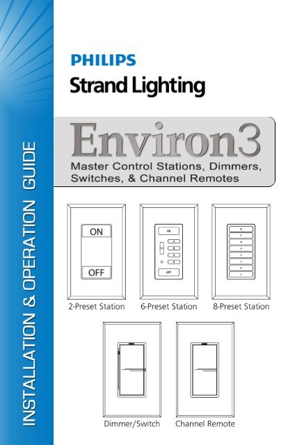
<strong>Environ</strong> 3 <strong>Control</strong> <strong>Stations</strong><br />
Installation & Operation Guide<br />
Important Safeguards<br />
When using electrical equipment, basic safety precautions should always be followed<br />
including the following:<br />
a. READ AND FOLLOW ALL SAFETY INSTRUCTIONS.<br />
b. Do not use outdoors.<br />
c. Do not mount near gas or electric heaters.<br />
d. Equipment should be mounted in locations and at heights where it will not<br />
readily be subjected to tampering by unauthorized personnel.<br />
e. The use of accessory equipment not recommended by the manufacturer<br />
may cause an unsafe condition.<br />
f. Do not use this equipment for other than intended use.<br />
g. Refer service to qualified personnel.<br />
SAVE THESE INSTRUCTIONS.<br />
WARNING: You must have access to a main circuit breaker or other power<br />
disconnect device before installing any wiring. Be sure that power is disconnected<br />
by removing fuses or turning the main circuit breaker off before installation.<br />
Installing the device with power on may expose you to dangerous voltage and<br />
damage the device. A qualified electrician must perform this installation.<br />
WARNING: Refer to National Electrical Code® and local codes for cable<br />
specifications. Failure to use proper cable can result in damage to equipment or<br />
danger to persons.<br />
CAUTION: Wire openings MUST have fittings or lining to protect wires/cables<br />
from damage. Use 75° C copper wire only! Aluminum wire may not be used.<br />
1
Installation & Operation Guide<br />
<strong>Environ</strong> 3 <strong>Control</strong> <strong>Stations</strong><br />
TABLE OF CONTENTS<br />
Preface .......................................................................................................................................3<br />
About this Guide .................................................................................................................. 3<br />
Additional Manuals.............................................................................................................. 4<br />
Product Overview .....................................................................................................................5<br />
<strong>Environ</strong> 3 <strong>Master</strong> <strong>Control</strong> <strong>Stations</strong>, Dimmers, Switches, and Channel Remotes ................ 5<br />
Installation Guidelines ..............................................................................................................7<br />
General Installation Guidelines............................................................................................ 7<br />
Ganging and Derating Heatsink Devices ............................................................................. 8<br />
<strong>Environ</strong> 3 <strong>Master</strong> <strong>Control</strong> <strong>Stations</strong> ............................................................................................9<br />
<strong>Master</strong> <strong>Control</strong> Station Installation ...................................................................................... 9<br />
<strong>Master</strong> <strong>Control</strong> Station Operation ...................................................................................... 10<br />
Programming Presets.......................................................................................................... 12<br />
Changing the Fade Rate ..................................................................................................... 13<br />
Setting the Button Brightness............................................................................................. 14<br />
Replacing a Keypad Membrane ......................................................................................... 15<br />
<strong>Environ</strong> 3 Dimmers/Switches/Channel Remotes ....................................................................16<br />
Dimmer/Switch Installation ............................................................................................... 16<br />
Switch (Non-Dim) Setup.................................................................................................... 17<br />
Dimmer/Switch Operation ................................................................................................. 18<br />
Channel Remote Installation .............................................................................................. 19<br />
Channel Remote Operation ................................................................................................ 20<br />
Specifications ..........................................................................................................................21<br />
<strong>Environ</strong> 3 <strong>Master</strong> <strong>Control</strong> Station / Dimmer / Switch / Channel Remote.......................... 21<br />
2
<strong>Environ</strong> 3 <strong>Control</strong> <strong>Stations</strong><br />
Installation & Operation Guide<br />
PREFACE<br />
About this Guide<br />
The document provides installation and operation instructions for the following <strong>Environ</strong> 3<br />
products.<br />
<strong>Master</strong> <strong>Control</strong> <strong>Stations</strong>:<br />
• 61204 <strong>Environ</strong> 3 Pushbutton Station, 2 Presets, 1-Gang, 120V<br />
• 61204H <strong>Environ</strong> 3 Pushbutton Station, 2 Presets, Fins, 1-Gang, 120V<br />
• 61200 <strong>Environ</strong> 3 Pushbutton Station, 5 Presets, Raise/Lower, IR Rec., 1-Gang, 120V<br />
• 61202 <strong>Environ</strong> 3 Pushbutton Station, 5 Presets, Raise/Lower, IR Rec., A/V In., 1-Gang, 120V<br />
• 61200H <strong>Environ</strong> 3 Pushbutton Station, 5 Presets, Raise/Lower, IR Rec., Fins, 1-Gang, 120V<br />
• 61202H <strong>Environ</strong> 3 Pushbutton Station, 5 Presets, Raise/Lower, IR Rec., A/V In., Fins,<br />
1-Gang, 120V<br />
• 61201 <strong>Environ</strong> 3 Pushbutton Station, 8 Presets, 1-Gang, 120V<br />
• 61203 <strong>Environ</strong> 3 Pushbutton Station, 8 Presets, A/V In., 1-Gang, 120V<br />
• 61201H <strong>Environ</strong> 3 Pushbutton Station, 8 Presets, Fins, 1-Gang, 120V<br />
• 61203H <strong>Environ</strong> 3 Pushbutton Station, 8 Presets, A/V In., Fins, 1-Gang, 120V<br />
Strap Style Power Devices:<br />
• 61221 <strong>Environ</strong> 3 Electronic Low Voltage Strap Dimmer 300VA, 1-Gang, 120V<br />
• 61220 <strong>Environ</strong> 3 Incandescent/Inductive Strap Dimmer 600VA, Fins, 1-Gang, 120V<br />
• 61222 <strong>Environ</strong> 3 Non-Dim Strap Switch 600VA, 1-Gang, 120V<br />
• 61223 <strong>Environ</strong> 3 PowerSpec® HDF Fluorescent Strap Dimmer 600VA, 1-Gang, 120V<br />
• 61224 <strong>Environ</strong> 3 Advance Mark 10® Strap Dimmer 600VA, 1-Gang, 120V<br />
• 61225 <strong>Environ</strong> 3 3-Speed Strap Fan <strong>Control</strong> 1.5 Amp, 1-Gang, 120V<br />
• 61228 <strong>Environ</strong> 3 Dimmer/Non-Dim/Fan Strap Channel Remote, 1-Gang, 120V<br />
Heatsink Style Power Devices:<br />
• 61234 <strong>Environ</strong> 3 Electronic Low Voltage Heatsink Dimmer 500VA, Fins, 1-Gang, 120V<br />
• 61230 <strong>Environ</strong> 3 Incandescent/Inductive Heatsink Dimmer 600VA, Fins, 1-Gang, 120V<br />
• 61231 <strong>Environ</strong> 3 Incandescent/Inductive Heatsink Dimmer 1000VA, Fins, 1-Gang, 120V<br />
• 61232 <strong>Environ</strong> 3 Incandescent/Inductive Heatsink Dimmer 1500VA, Fins, 2-Gang, 120V<br />
• 61233 <strong>Environ</strong> 3 Incandescent/Inductive Heatsink Dimmer 2000VA, Fins, 2-Gang, 120V<br />
• 61235 <strong>Environ</strong> 3 Non-Dim Heatsink Switch 1000VA, 1-Gang, 120V<br />
• 61236 <strong>Environ</strong> 3 Non-Dim Heatsink Switch 2000VA, 2-Gang, 120V<br />
• 61237 <strong>Environ</strong> 3 PowerSpec® HDF Fluorescent Heatsink Dimmer 600VA, Fins, 1-Gang,<br />
120V<br />
• 61238 <strong>Environ</strong> 3 PowerSpec® HDF Fluorescent Heatsink Dimmer 1500VA, Fins, 2-Gang,<br />
120V<br />
• 61239 <strong>Environ</strong> 3 Advance Mark 10® Heatsink Dimmer 600VA, Fins, 1-Gang, 120V<br />
• 61240 <strong>Environ</strong> 3 Advance Mark 10® Heatsink Dimmer 1000VA, Fins, 1-Gang, 120V<br />
• 61241 <strong>Environ</strong> 3 Advance Mark 10® Heatsink Dimmer 1500VA, Fins, 2-Gang, 120V<br />
• 61242 <strong>Environ</strong> 3 3-Speed Heatsink Fan <strong>Control</strong> 1.5 Amp, Fins, 1-Gang, 120V<br />
• 61245 <strong>Environ</strong> 3 Dimmer/Non-Dim/Fan Heatsink Channel Remote, 1-Gang, 120V<br />
3
Installation & Operation Guide<br />
<strong>Environ</strong> 3 <strong>Control</strong> <strong>Stations</strong><br />
Please read all instructions before installing or using this product. Retain this guide for future<br />
reference.<br />
IMPORTANT INFORMATION. PLEASE READ!<br />
This equipment is intended for installation in accordance with the National Electric Code®<br />
and local regulations. It is also intended for permanent installation in indoor applications only.<br />
Before any electrical work is performed, disconnect power at the circuit breaker or remove the<br />
fuse to avoid shock or damage to the control. It is recommended that a qualified electrician<br />
perform this installation.<br />
Additional Manuals<br />
The complete library of <strong>Environ</strong> 3 Preset Dimming Product manuals may be downloaded at<br />
www.strandlighting.com. These manuals include:<br />
• <strong>Environ</strong> 3 Preset Dimming System (Complete Manual)<br />
• <strong>Environ</strong> 3 <strong>Master</strong> <strong>Control</strong> <strong>Stations</strong>, Dimmers, Switches, Channel Remotes<br />
• <strong>Environ</strong> 3 Fan <strong>Control</strong><br />
• <strong>Environ</strong> 3 Power Extender<br />
• <strong>Environ</strong> 3 Infrared Transmitter<br />
• <strong>Environ</strong> 3 IR Receivers<br />
• <strong>Environ</strong> 3 Relay Module<br />
• <strong>Environ</strong> 3 Vision.net To <strong>Environ</strong> 3 Digital Interface<br />
4
<strong>Environ</strong> 3 <strong>Control</strong> <strong>Stations</strong><br />
Installation & Operation Guide<br />
PRODUCT OVERVIEW<br />
<strong>Environ</strong> 3 <strong>Master</strong> <strong>Control</strong> <strong>Stations</strong>, Dimmers, Switches, and Channel<br />
Remotes<br />
ON<br />
OFF<br />
<strong>Environ</strong> 3 Pushbutton Station, 2-Presets: Features oversized illuminated<br />
push buttons for easy operation. It is intended for use as an simple<br />
entry station for locations that require a more industrial button style.<br />
With its positive-feedback LED indication and tactile feel the unit permits<br />
the recall of two preset scenes. Over 120 pre-defined labels are<br />
available to install inside these oversized button. Custom engraved faceplates<br />
may also be ordered for these stations.<br />
<strong>Environ</strong> 3 Pushbutton Station, 5-Presets: Features standard sized illuminated<br />
pushbuttons with positive-feedback LED indication and tactile<br />
feel. This station permits the recall of preset scenes, in addition to the<br />
global raise/lower of up to 30 dimmers and master keypads on the network.<br />
Each control station has an integral infrared receiver that can be<br />
used in conjunction with an optional hand-held infrared transmitter.<br />
Certain models of this station feature an "A/V In" Audio/Visual contact<br />
closure input which may be wired to our IR Receiver units, or any third<br />
party control system that generates a contact closure signal. Custom button<br />
membranes may be engraved with your choice of nomenclature.<br />
Custom engraved faceplates may also be ordered for these stations.<br />
<strong>Environ</strong> 3 Pushbutton Station, 8-Presets: Features smaller sized illuminated<br />
pushbuttons with positive-feedback LED indication and tactile<br />
feel. This station permits the recall of preset scenes, in addition to the<br />
global raise/lower of up to 30 dimmers and master keypads on the network.<br />
Certain models of this station feature an "A/V In" Audio/Visual<br />
contact closure input which may be wired to our IR Receiver units or<br />
any third party control system that generates a contact closure signal.<br />
Custom button membranes may be engraved with your choice of<br />
nomenclature. Custom engraved faceplates may also be ordered for<br />
these stations.<br />
5
Installation & Operation Guide<br />
<strong>Environ</strong> 3 <strong>Control</strong> <strong>Stations</strong><br />
<strong>Environ</strong> 3 Dimmers/Switches: <strong>Environ</strong> 3 Dimmers/Switches are digital,<br />
micro-touch preset dimmers or Non Dims. These units are equipped<br />
with an automatic fade and dual LED readout, providing full-function,<br />
3-way and multi-location control when used with <strong>Environ</strong> 3 Channel<br />
Remotes. Dimmers are available for a variety of load types including;<br />
Low Voltage, Incandescent/Inductive, Non-Dim/Switch, PowerSpec®<br />
HDF Fluorescent, Advance Mark 10® Fluorescent, Neon, and Cold<br />
Cathode. Custom engraved faceplates may also be ordered for these<br />
devices.<br />
<strong>Environ</strong> 3 Channel Remotes: <strong>Environ</strong> 3 Channel Remotes provide<br />
multilocation remote devices that use 3-way wiring to remotely control<br />
<strong>Environ</strong> 3 dimmers, switches or fan controls. An unlimited number of<br />
remotes can be used for multi-location control. These devices do not<br />
count against the 30 device limitation of the <strong>Environ</strong> 3 network, as they<br />
utilize "the yellow wire" to connect and control devices on "the purple<br />
wire". Custom engraved faceplates may also be ordered for this remote.<br />
6
<strong>Environ</strong> 3 <strong>Control</strong> <strong>Stations</strong><br />
Installation & Operation Guide<br />
INSTALLATION GUIDELINES<br />
General Installation Guidelines<br />
1. Per the National Electric Code, <strong>Environ</strong> 3 dimmers require that the neutral wire be<br />
considered a current carrying conductor. Each circuit feeding an <strong>Environ</strong> 3 dimmer or a<br />
<strong>Environ</strong> 3 dimmed load requires a separate neutral. No shared or common neutrals are<br />
allowed. Shared neutrals will result in an undesirable flashing of controlled loads.<br />
2. Use Quiet Electronic (QE) dimmers to control only low-voltage fixtures that have<br />
electronic, solid-state transformers and regular incandescent loads.<br />
3. Use HDF Direct drive dimmers to control fluorescent lighting loads at 120V with<br />
approved <strong>Strand</strong> HDF Electronic Ballasts only.<br />
4. Use Electronic Ballast (EB) Direct Drive Dimmers to control Advance Mark 10®<br />
Dimmable Electronic Ballast.<br />
5. <strong>Environ</strong> 3 Strap Dimmers, <strong>Master</strong>s, Switches, and Channel Remotes are mounted<br />
individually or ganged together, and are supplied without faceplates. They accept <strong>Strand</strong><br />
single and multi-gang Faceplates or standard decorator-style faceplates by others.<br />
Faceplates are not included with the Dimmers, <strong>Master</strong>s, Switches or Remotes, and must<br />
be ordered separately. Heatsink devices cannot be ganged with Strap devices.<br />
6. <strong>Environ</strong> 3 Heatsink Dimmers, <strong>Master</strong>s, Switches and Channel Remotes incorporate lowprofile<br />
heatsinks and are supplied with single-gang faceplates. Multi-gang faceplates are<br />
also available. Heatsink devices mount side-by-side with no fins broken (NFB) and do<br />
not need to be derated. Heatsink devices cannot be ganged with Strap devices. When<br />
mounting devices with one or both fins removed, it is necessary to derate the maximum<br />
load of the devices. Refer to the derating chart on page 8.<br />
7. <strong>Environ</strong> 3 Dimmers or Switches may be fed individually or in groups, regardless of<br />
phase.<br />
8. <strong>Environ</strong> 3 <strong>Master</strong> <strong>Control</strong> <strong>Stations</strong> draw approximately one watt and may be fed from any<br />
circuit. Multiple masters may be inter-connected. On an single <strong>Environ</strong> 3 network, the<br />
total number of dimmers and masters are not to exceed 30. An unlimited number of<br />
channel remotes may be used.<br />
9. Dimmers can be connected to optional HDF dimming interfaces as well as dimming<br />
amplifiers. Please consult interface and amplifier instructions for wiring. Non-dim<br />
switches can be connected to <strong>Environ</strong> 3 relay modules for 277V loads.<br />
10. Do not connect <strong>Environ</strong> 3 dimmers to Ground Fault Interrupt (GFI) or Ground Fault<br />
Circuit Interrupter (GFCI) circuit breakers.<br />
7
Installation & Operation Guide<br />
<strong>Environ</strong> 3 <strong>Control</strong> <strong>Stations</strong><br />
Ganging and Derating Heatsink Devices<br />
No Fins Broken - Separate Wallboxes<br />
Devices of matching depth can be<br />
mounted next to each other in separate<br />
single gang wallboxes. The boxes must<br />
be spaced to the dimensions shown in<br />
Figure 1. Allow 6" of clearance above<br />
and below the dimmers.<br />
Note: For ease of installation, add 1/8"<br />
to each horizontal dimension shown in<br />
Figure 1. Faceplate depth: 5/8".<br />
2-3/4" 3-5/8" 4-1/2"<br />
No Fins Broken No Fins Broken<br />
2-3/4" 4-1/2"<br />
Fins Broken Fins Broken<br />
1-5/16" 3-5/8"<br />
3/8"<br />
No Fins Broken - Multi-gang Wallbox<br />
4-11/16"<br />
When mounting devices with no fins<br />
removed, use Table A to determine what<br />
size multi-gang wallbox is required.<br />
Notes:<br />
• When installing a even number of<br />
small devices, only use wallbox<br />
size listed in Table A and space<br />
one additional box 3/4" away from<br />
the others.<br />
• When combining small and large<br />
devices, be certain to position a<br />
small device at one end and a<br />
large device at the other end of the<br />
multi-gang box.<br />
• Mount dimmers with heatsink fins<br />
aligned vertically.<br />
Fins Broken - Multi-gang Wallbox<br />
When mounting devices with fins broken<br />
in multi-gang boxes, follow information<br />
in Table B to determine the<br />
correct wallbox size.<br />
Fins Broken - Derating<br />
When mounting devices with one or<br />
both fins removed it is necessary to derate<br />
the maximum load of the devices as<br />
shown in Table C.<br />
Figure 1: Mounting Dimensions<br />
Table A – No Fins Broken Multi Gang Wallbox<br />
Number of Large Devices<br />
Number of<br />
Small Devices<br />
0<br />
1<br />
2<br />
3<br />
4<br />
5<br />
6<br />
0<br />
0<br />
1<br />
1+1<br />
4<br />
4+1<br />
7<br />
7+1<br />
1<br />
1<br />
3<br />
5<br />
6<br />
8<br />
9<br />
11<br />
2<br />
4<br />
6<br />
7<br />
9<br />
10<br />
12<br />
13<br />
3<br />
6<br />
8<br />
10<br />
11<br />
13<br />
14<br />
16<br />
4<br />
9<br />
11<br />
12<br />
14<br />
15<br />
17<br />
18<br />
Table B – Fins Broken Multi-Gang Wallbox<br />
Number of<br />
Small Devices<br />
0<br />
1<br />
2<br />
3<br />
4<br />
5<br />
Number of Large Devices<br />
0 1 2 3 4 5<br />
1 3 5 7 9<br />
1 3 5 7 9 11<br />
2 4 6 8 10 12<br />
3 5 7 9 11 13<br />
4 6 8 10 12 14<br />
5 7 9 11 13 15<br />
Table C – Fins Broken Derating Chart<br />
Device Max.<br />
Load<br />
500VA<br />
600VA<br />
1000VA<br />
1500VA<br />
2000VA<br />
Wallbox Dimmers– No Fins<br />
one side<br />
425VA<br />
600VA<br />
800VA<br />
1300VA<br />
1800VA<br />
both sides<br />
350VA<br />
500VA<br />
700VA<br />
1100VA<br />
1600VA<br />
8
<strong>Environ</strong> 3 <strong>Control</strong> <strong>Stations</strong><br />
Installation & Operation Guide<br />
ENVIRON 3 MASTER CONTROL STATIONS<br />
<strong>Master</strong> <strong>Control</strong> Station Installation<br />
CAUTION: Before any electrical work is performed, disconnect power at the<br />
circuit breaker or remove the fuse to avoid shock or damage to the unit.<br />
Step<br />
1. If using screwless faceplate (sold separately), before connecting any wires, be sure<br />
that the faceplate mounting adapter plate is behind the device with alignment tabs<br />
facing forward. Tabs should rest within centering holes of mounting strap.<br />
Step 2. Connect the <strong>Master</strong> Station wires to the wallbox wires as follows (Figure 2):<br />
a. Black to Hot (120V AC Source)<br />
b. White to Neutral *<br />
c. Purple to Network Connection (Line Voltage Class 1) **<br />
Step<br />
3. Be sure the Ground wire (Green) is connected to earth ground. Note: Failure to<br />
connect ground properly may result in improper operation or damage to unit.<br />
Faceplate<br />
<strong>Master</strong>/Remote<br />
Station<br />
Wire Nut<br />
Black Hot<br />
White Neutral<br />
Purple Network<br />
Green* Ground<br />
Wallbox<br />
* or bare wire<br />
Mounting Screws<br />
(provided)<br />
Figure 2: Installing a <strong>Master</strong> Station<br />
9
Installation & Operation Guide<br />
<strong>Environ</strong> 3 <strong>Control</strong> <strong>Stations</strong><br />
Note: <strong>Environ</strong> 3 Strap-Style <strong>Master</strong> <strong>Stations</strong> do not have a ground wire. <strong>Environ</strong> 3 Heatsink-<br />
Style <strong>Master</strong> <strong>Stations</strong> have a bare wire, which must be connected to ground.<br />
Step 4. For <strong>Master</strong> <strong>Stations</strong> with AV inputs, refer to "Low-Voltage Wire (Momentary Dry<br />
Contact) Identification" on page 11 for wiring to other devices.<br />
Step 5. Ensure all wire connections are tight and no bare copper is exposed.<br />
Step 6. Install device into wallbox, making sure that all wires are neatly installed into<br />
wallbox. Using mounting screws provided, secure <strong>Master</strong> Station into wallbox.<br />
Step 7. Install faceplate.<br />
* The White wire must be connected to the neutral wire in the wallbox. Failure to<br />
connect the White wire to the neutral will result in improper operation.<br />
** Link all <strong>Environ</strong> 3 devices using one line voltage wire connected between each<br />
Purple wire. Connected wires will operate as a system.<br />
<strong>Master</strong> <strong>Control</strong> Station Operation<br />
• Press or Tap the ON button to elegantly<br />
illuminate the entire area to the ON "preset"<br />
(when a <strong>Master</strong> Station is in a Preset, the ON<br />
button will illuminate at 25% intensity). If a<br />
dimmer’s global fade rate is set between 1.5<br />
and 7.5 seconds, the ON Preset will ramp up at<br />
the 1.5 second rate. If the global fade rate is set<br />
for 15 seconds or greater, the ON Preset will<br />
ramp at the 3 second rate.<br />
• Press and hold the RAISE/LOWER button to<br />
brighten/dim lighting level. Ramping is at a 3<br />
second rate.<br />
• Press or Tap the OFF button to fade lights to OFF<br />
Raise/Lower<br />
Buttons<br />
IR Receiver<br />
Figure 3: <strong>Master</strong> Station<br />
• Tap a Preset button to access one of the "preset" light levels. The fade up/down time<br />
depends on the selected fade rate.<br />
• Two quick taps of any button (except RAISE or LOWER) will fade the lighting quickly.<br />
10
<strong>Environ</strong> 3 <strong>Control</strong> <strong>Stations</strong><br />
Installation & Operation Guide<br />
Low-Voltage Wire (Momentary Dry Contact) Identification<br />
5-Preset<br />
<strong>Master</strong><br />
61202<br />
61202H<br />
Wire Color /<br />
Function<br />
Brown<br />
Button Common<br />
Red<br />
On Button<br />
Orange<br />
A Button<br />
Yellow<br />
B Button<br />
Green<br />
C Button<br />
Blue<br />
D Button<br />
White w/<br />
Violet Stripe<br />
Off Button<br />
Grey<br />
+5V<br />
White w/<br />
Red Stripe<br />
Raise Button<br />
White w/<br />
Green Stripe<br />
Lower Button<br />
Infrared<br />
Receiver<br />
(Wall)<br />
Infrared<br />
Receiver<br />
(Ceiling)<br />
61206 61207<br />
Terminal<br />
Strip #<br />
Wire<br />
Color<br />
1 Brown<br />
8-Preset<br />
<strong>Master</strong><br />
61203<br />
61203H<br />
Wire Color / Function<br />
Brown Button<br />
Common<br />
2 Red N/A<br />
3 Orange N/A<br />
4 Yellow N/A<br />
5 Green N/A<br />
6 Blue N/A<br />
7 Violet N/A<br />
8 Grey Grey +5V<br />
N/A N/A N/A<br />
N/A N/A N/A<br />
Notes:<br />
• To activate a button function from the low-voltage wiring, a simple<br />
momentary closure (contact) is required. This wiring connection<br />
must be from the button control wire (ex: red wire for the ON<br />
button) to the button common wire (brown). To ensure reliable<br />
operation, this closure should be of the dry contact type.<br />
• For buttons A–L, the closure duration should be between 50 and<br />
300 milliseconds. The ON and OFF button closures should be<br />
between 50 and 300 milliseconds. The RAISE and LOWER button<br />
closures must be at least 50 milliseconds.<br />
• The +5V wire (grey) should only be connected to the devices<br />
shown in the table above. Connecting this wire to any other device<br />
may damage the master.<br />
• Cap off any unused (N/A) wires.<br />
Red<br />
E Button<br />
White w/ Violet Stripe<br />
F Button<br />
Orange<br />
G Button<br />
Yellow<br />
H Button<br />
Green<br />
I Button<br />
Blue<br />
J Button<br />
White w/ Red Stripe<br />
K Button<br />
White w/ Green Stripe<br />
L Button<br />
11
Installation & Operation Guide<br />
<strong>Environ</strong> 3 <strong>Control</strong> <strong>Stations</strong><br />
Programming Presets<br />
After you have completed installation of all <strong>Environ</strong> 3 devices and have energized the system,<br />
programming of each Preset can be performed.<br />
To program a Preset:<br />
Step 1. Tap the preset button (ON, A – L) on the <strong>Master</strong> Station that you wish to program<br />
(Figure 4).<br />
Step 2. Adjust each <strong>Environ</strong> 3 Dimmer to the desired intensity and the <strong>Environ</strong> 3 Switches<br />
to either ON or OFF. (Refer to Figure 5 on next page.)<br />
Step 3. Press the Set button on each device after all devices have been adjusted.<br />
Repeat Steps 1-3 until all Presets have been programmed.<br />
Note: Dimmers cannot be programmed off for the "ON" preset. Non-dim switches may be<br />
programmed "OFF".<br />
On<br />
Off<br />
ON<br />
OFF<br />
Preset Buttons<br />
(On, A, B, C, D)<br />
Off<br />
Preset Buttons<br />
(E-L)<br />
Figure 4: <strong>Master</strong>/Remote Station <strong>Control</strong>s<br />
12
<strong>Environ</strong> 3 <strong>Control</strong> <strong>Stations</strong><br />
Changing the Fade Rate<br />
<strong>Environ</strong> 3 Dimmers can be programmed<br />
for 12 different fade rates.<br />
Dimmers can be programmed to have a<br />
different fade rate on each Preset. The<br />
fade rate choices are:<br />
• 1.5 seconds<br />
• 3 seconds<br />
• 4.5 seconds<br />
• 7.5 seconds<br />
• 15 seconds<br />
• 30 seconds<br />
• 1 minute<br />
• 2 minutes<br />
• 5 minutes<br />
• 15 minutes<br />
• 30 minutes<br />
• 60 minutes<br />
2 min<br />
1 min<br />
30 sec<br />
15 sec<br />
7.5 sec<br />
4.5 sec<br />
3 sec<br />
1.5 sec<br />
Green<br />
LED Lights<br />
Installation & Operation Guide<br />
60 min<br />
30 min<br />
15 min<br />
5 min<br />
Global Fade Rate = One fade rate for<br />
all Presets<br />
Each dimmer’s fade rate affects all Presets.<br />
Example: Dimmer #1 fade rate set<br />
7.5 sec., dimmer #2 set to 15 sec., dimmer<br />
#3 set to 3 sec. When any Preset is<br />
selected dimmers #1, 2, 3, will respond<br />
with 7.5, 15 and 3 seconds, respectively<br />
for ON, OFF, 1, 2, 3, 4, 5, 6, 7, 8, 9, 10,<br />
11, and 12.<br />
Press and hold<br />
Top/Bottom to<br />
Raise/Lower<br />
Intensity<br />
Set Button<br />
Figure 5: Dimmer/Switch <strong>Control</strong><br />
To change the Global Fade Rate that affects all Presets:<br />
Step 1. Tap the OFF button on the <strong>Master</strong> Station.<br />
Step 2. Press and hold the Set button. After 3 seconds, either a single green LED or a pair of<br />
green LEDs will indicate the current "global" fade rate. The bottom LED indicates<br />
the 1.5 second fade rate, the next LED up is 3 seconds, ...the top LED is 2 minutes.<br />
If the bottom two LEDs are on, it indicates the 5 minute fade rate, if the next two<br />
LEDs up are lit, it indicates 15 minutes, ... the top two LEDs indicate the 60 minute<br />
fade rate.<br />
Note: When the two LEDs are on, they will not be at the same intensity.<br />
Step 3. While holding the Set button, tap the top of the rocker to sequence the LEDs<br />
through the various fade rates until the desired fade rate is selected.<br />
Step 4. Release the Set button.<br />
Step 5. Repeat steps 2-4 for each device.<br />
13
Installation & Operation Guide<br />
<strong>Environ</strong> 3 <strong>Control</strong> <strong>Stations</strong><br />
To change the fade rate that will affect only an individual Preset:<br />
Step 1. Tap a Preset button on the <strong>Master</strong> Station to go to a Preset.<br />
Step 2. Press and hold the Set button.<br />
Step 3. After 3 seconds, either a single green LED or a pair of green LEDs will indicate the<br />
Preset's fade rate.<br />
Step 4. While holding the Set button, tap the top rocker until the desired fade rate is<br />
reached.<br />
Step 5. Release the Set button.<br />
Step 6. Repeat above for each device.<br />
Setting the Button Brightness<br />
The <strong>Environ</strong> 3 <strong>Master</strong> Station’s button brightness can be programmed for 100% (factory<br />
default), 75%, 50%, or 25% brightness.<br />
5-Preset<br />
<strong>Master</strong><br />
A<br />
B<br />
C<br />
D<br />
8-Preset<br />
<strong>Master</strong><br />
G<br />
H<br />
I<br />
J<br />
LED<br />
Brightness<br />
100%<br />
75%<br />
50%<br />
25%<br />
To change the setting:<br />
Step 1. On a 5-Preset <strong>Master</strong> Station, press and hold buttons "B" and "D" simultaneously<br />
for 3 seconds (on an 8-Preset <strong>Master</strong> Station, press buttons "H" and "J"). On a 5-<br />
Preset <strong>Master</strong> Station, buttons "A" thru "D" will illuminate (on an 8-Preset <strong>Master</strong><br />
Station, buttons "G" thru "J" will illuminate). The blinking LED displays the current<br />
LED brightness setting. The continuously-illuminated LEDs display the available<br />
brightness settings that can be selected.<br />
Step 2. To change the brightness setting, press the button illuminated at the desired<br />
brightness. This button will begin blinking.<br />
Step 3. To save the selected brightness and exit the mode, press the ON button on a 5-Preset<br />
<strong>Master</strong> Station ( or the "E" button on an 8-Preset <strong>Master</strong> Station). All buttons on<br />
that <strong>Master</strong> Station will now have the new brightness setting.<br />
14
<strong>Environ</strong> 3 <strong>Control</strong> <strong>Stations</strong><br />
Installation & Operation Guide<br />
Replacing a Keypad Membrane<br />
The overlay is easily replaced, even if the unit is currently installed. See the <strong>Environ</strong> 3 Preset<br />
Dimming System manual for more information on ordering optional custom keypad membranes.<br />
To replace a keypad membrane:<br />
Step 1. Turn the power off at the circuit breaker.<br />
Step 2. Remove the faceplate (Figure 6).<br />
Step 3. Remove the keypad wall screws.<br />
a. On Heatsink model, remove heatsink screws and spacers. (Spacers are not<br />
attached to the unit).<br />
Step 4. Remove the retaining plate screws and plate.<br />
Step 5. Remove the existing keypad membrane.<br />
Step 6. Install the new keypad membrane, being careful to line it up properly with the<br />
openings.<br />
Step 7. Reinstall the retaining plate screws.<br />
a. On Heatsink model, reinstall screws and spacers.<br />
Step 8. Reinstall the keypad to wallbox.<br />
Step 9. Reinstall the faceplate.<br />
Step 10. Turn the power back on at the circuit breaker.<br />
Keypad<br />
Membrane<br />
Wall Screw (2)<br />
Button<br />
Station<br />
Plate Screw (2)<br />
Faceplate<br />
Figure 6: Replacing Keypad Membrane<br />
15
Installation & Operation Guide<br />
<strong>Environ</strong> 3 <strong>Control</strong> <strong>Stations</strong><br />
ENVIRON 3 DIMMERS/SWITCHES/CHANNEL REMOTES<br />
Dimmer/Switch Installation<br />
Step<br />
CAUTION: Before any electrical work is performed, disconnect power at the<br />
circuit breaker or remove the fuse to avoid shock or damage to the unit.<br />
1. If you are replacing an existing device with a <strong>Environ</strong> 3 Dimmer or Switch:<br />
a. Remove faceplate from existing device<br />
b. Unscrew and pull device out of wallbox.<br />
c. Disconnect wires from device. Using a voltage tester, identify and mark the<br />
"hot" and the "load" wires connected to the device.<br />
Faceplate<br />
Mounting Screws<br />
(provided)<br />
Wire Nut<br />
Black Hot<br />
White Neutral<br />
Red Load<br />
Yellow Remote<br />
Purple Network<br />
Ground Strap<br />
(provided) Ground<br />
Wire<br />
Wallbox<br />
Dimmer/Switch<br />
Figure 7: Installing a Dimmer/Switch<br />
Step 2. If using screwless faceplate (sold separately), before connecting any wires, be sure<br />
that faceplate mounting adapter plate is behind device with alignment tabs facing<br />
forward. Tabs should rest within centering holes of aluminum mounting strap.<br />
Step 3. Be sure that the Dimmer or Switch is in "System Off" position by firmly pressing<br />
the bottom of the device until it snaps into place and the "System Off" label at the<br />
top of device is exposed.<br />
Step 4. Connect the Dimmer/Switch wires to the wallbox wires as follows (Figure 7):<br />
a. Black to Hot (120V AC Source)<br />
b. White to Neutral *<br />
c. Red to Load (Light Fixture)<br />
d. Yellow to Remote. (Cap yellow if remote is not used.)<br />
e. Purple to Network Connection (Line Voltage Class 1) **<br />
Step 5. Be sure the Ground wire (bare stranded) is connected to earth ground.<br />
16
<strong>Environ</strong> 3 <strong>Control</strong> <strong>Stations</strong><br />
Installation & Operation Guide<br />
Note: Miswiring or failure to connect ground may result in improper operation of the device.<br />
Step 6. Ensure all wire connections are tight and no bare copper is exposed.<br />
Step 7. Install device into wallbox, making sure that all wires are neatly installed into<br />
wallbox. Using mounting screws provided, secure device into wallbox.<br />
Step 8. Install faceplate.<br />
* The White wire must be connected to the neutral wire in the wallbox. Failure to<br />
connect the White wire to the neutral will result in improper operation.<br />
** Link all <strong>Environ</strong> 3 devices using one line voltage wire connected between each<br />
Purple wire. Connected devices will operate as a system.<br />
Switch (Non-Dim) Setup<br />
The <strong>Environ</strong> 3 Universal programmable switch can be programmed as a 4 or 5-Preset non-dim<br />
switch. When programmed as a 5-Preset device, it is not suitable for 3-way applications.<br />
The default mode of the switch is as a normal (4-Preset) non-dim device. The AV (5-Preset)<br />
mode allows the non-dim switch to remain off when the master ON button is pressed.<br />
To change the mode of the switch:<br />
Step 1. Tap OFF on the <strong>Master</strong> Station to place the<br />
switch in the OFF Preset.<br />
Step 2. Press and hold the Set button (Figure 8).<br />
After 3 Seconds, a green LED will<br />
illuminate on the bargraph. If the switch is<br />
currently in normal mode, the bottom green<br />
LED will illuminate. If it is in AV mode, the<br />
top LED will illuminate.<br />
Bargraph<br />
Step 3. Tap the top of the rocker once to toggle the<br />
mode.<br />
Step 4. Release the Set button.<br />
Rocker<br />
Switch<br />
Set Button<br />
Figure 8: Dimmer/Switch<br />
Note: In normal mode, a "soft start" feature is utilized to extend lamp life. In AV mode, the<br />
"soft start" is not implemented.<br />
17
Installation & Operation Guide<br />
<strong>Environ</strong> 3 <strong>Control</strong> <strong>Stations</strong><br />
Dimmer/Switch Operation<br />
• To turn light on to preset level tap top of rocker.<br />
The dimmer will fade up at the 1.5 second rate.<br />
• A second tap of the rocker fades the dimmer to full<br />
brightness.<br />
• To adjust the light level, press and hold top or<br />
bottom of rocker until desired light level is<br />
reached, and then release. Ramping will be at the 3<br />
second rate.<br />
• To turn lights off, tap the bottom of the rocker. The<br />
dimmer will fade at the 3 second fade rate.<br />
• To quickly return to the preset level when light is<br />
on, quickly tap OFF and then ON. The lights will<br />
then adjust to the preset level.<br />
Rocker<br />
Switch<br />
Set Button<br />
Figure 9: Dimmer/Switch<br />
• To bypass the fade rate and turn the lights to full ON or OFF, double tap the dimmer for<br />
ON or OFF.<br />
• If the master is in the OFF Preset, the master ON button will illuminate when any<br />
dimmer is turned on.<br />
• To change the preset level of the current Preset:<br />
Press and hold the rocker until lights reach the desired level then release<br />
Press the Set button to save the preset in memory<br />
LED Status Indications:<br />
• Red LED is on when Dimmer/Switch is off to locate Dimmer/Switch when room is dark<br />
As many as three green LEDs may be illuminated at any given time. The bright green LED<br />
indicates the current level of the dimmer. The medium green LED indicates the preset level of<br />
the current Preset. The dim green LED indicates the preset level of the ON Preset.<br />
18
<strong>Environ</strong> 3 <strong>Control</strong> <strong>Stations</strong><br />
Installation & Operation Guide<br />
Channel Remote Installation<br />
The <strong>Environ</strong> 3 Channel Remote is a multi-location remote device that uses existing 3-way wiring<br />
to control <strong>Environ</strong> 3 Dimmers or Switches.<br />
CAUTION: Before any electrical work is performed, disconnect power at the<br />
circuit breaker or remove the fuse to avoid shock or damage to the unit.<br />
Note:<br />
• If replacing an existing device with this device begin with Step #1.<br />
• If installing this device in new construction begin with Step #4.<br />
Step 1. Disconnect power at panelboard.<br />
Step 2. Remove faceplate from existing device.<br />
Step 3. Unscrew and pull device out of wallbox.<br />
Step 4. Disconnect wires from device. Using a wire box tester, identify and mark "Hot" and<br />
"Traveler" wires connected to device.<br />
Step 5. Install device as follows (refer to wiring on page 20):<br />
a. Be sure ground wire (bare stranded) is connected to earth ground.<br />
IMPORTANT: Miswiring, or failure to connect ground, may result in improper<br />
operation of device.<br />
b. If using screwless faceplate (sold separately), before connecting any wires, be<br />
sure that faceplate mounting adapter plate is behind device with alignment tabs<br />
facing forward. Tabs should rest within centering holes of aluminum mounting<br />
strap.<br />
Step 6. After all connections have been made, ensure all wire connectors are firmly<br />
attached.<br />
Step 7. Gently place wires and backbox into wallbox (with LED at top of device) and screw<br />
in place.<br />
Step 8. Before installing faceplate, restore power to circuit.<br />
Step 9. After testing device for proper operation, install faceplate onto the device.<br />
Wiring Notes<br />
Channel Remote to Wallbox Wires:<br />
Black Hot (120V. Source must be same phase as dimmer.)<br />
Yellow Traveler Wire from <strong>Environ</strong> 3 ON switch.<br />
Bare Copper Earth Ground.<br />
Grey * Ground or Neutral.<br />
* For Remote LED operation, connect grey to neutral or ground.<br />
19
Installation & Operation Guide<br />
<strong>Environ</strong> 3 <strong>Control</strong> <strong>Stations</strong><br />
• 61228/61245 Channel Remote can control one <strong>Environ</strong> 3 Dimmer or Switch from one or<br />
multiple locations.<br />
• 61228/61245 Channel Remote must be wired on the same circuit as the device it is<br />
controlling.<br />
• 61228/61245 Channel Remote provides manual override for any one device (channel) of<br />
an <strong>Environ</strong> 3 system.<br />
• Each circuit feeding dimmers and dimmed loads requires a separate neutral. Shared<br />
neutrals will result in undesirable flashing of controlled loads.<br />
• Line voltage must not be supplied by a GFI Breaker.<br />
To Load<br />
To Load<br />
To Load<br />
61200<br />
61222 61222<br />
61222<br />
61228 / 61245<br />
BLK<br />
120VAC<br />
WHT 120VAC<br />
N L<br />
L N<br />
L N<br />
120VAC<br />
L N<br />
120VAC<br />
YEL<br />
Figure 10: Channel Remote Wiring Diagram<br />
Channel Remote Operation<br />
Turn Lights on to Preset:<br />
• Tap rocker top once.<br />
Turn Lights Full On:<br />
• Tap rocker top twice.<br />
Adjust Light Level:<br />
• Press and Hold down rocker top or bottom<br />
until desired level is reached.<br />
• Release rocker<br />
Turn Lights Off:<br />
• Tap rocker bottom once or twice.<br />
• Lights fade off.<br />
Red LED<br />
Rocker Top<br />
Rocker Bottom<br />
Note: When properly installed, the remote’s red LED will be constantly lit at half brilliance.<br />
20
<strong>Environ</strong> 3 <strong>Control</strong> <strong>Stations</strong><br />
Installation & Operation Guide<br />
SPECIFICATIONS<br />
<strong>Environ</strong> 3 <strong>Master</strong> <strong>Control</strong> Station / Dimmer / Switch / Channel Remote<br />
Voltage:<br />
Operating Temp:<br />
Load:<br />
Input: 108-132 VAC, 60 Hz, ±3Hz<br />
0-40 Centigrade, 32-104 Fahrenheit<br />
Incan./Induc. Dimmers - Incandescent, low voltage incandescent with<br />
magnetic transformers, neon, cold cathode, or general inductive loads.<br />
Dedicated Neutral connection required<br />
ND Switches - Switched loads. Dedicated Neutral connection<br />
required.<br />
Elec. Low Voltage Dimmers - Electronic low voltage and incandescent<br />
loads. Dedicated Neutral connection required.<br />
HDF Dimmers - Fluorescent lighting loads with approved <strong>Strand</strong> HDF<br />
Electronic Ballasts. Dedicated Neutral connection required.<br />
Advance Mark 10® Dimmers - Fluorescent loads with Advance Mark<br />
10® electronic ballasts. Dedicated Neutral connection required.<br />
Dimensions:<br />
1.7"<br />
1.2"<br />
1.68"<br />
0.37"<br />
1.37"<br />
3.25"<br />
4.0"<br />
3.25"<br />
4.0"<br />
<strong>Master</strong>/Remote Station<br />
Dimmer/Switch<br />
2.61"<br />
0.50"<br />
1.2"<br />
4.36"<br />
0.50"<br />
1.2"<br />
3.25"<br />
3.25"<br />
4.50"<br />
4.50"<br />
500VA, 600VA, 1000VA Dimmers<br />
1500VA, 2000VA Dimmers<br />
21
Part No. 2-450212-020