R1-R4 ENSREG Stress Test - Summary
R1-R4 ENSREG Stress Test - Summary
R1-R4 ENSREG Stress Test - Summary

Create successful ePaper yourself
Turn your PDF publications into a flip-book with our unique Google optimized e-Paper software.
Detta ar en PDF-tolkning fran Darwin av dokument 2158963 / 2.0<br />
Sekretessklass: Hemlig<br />
Ringhals AB<br />
Dokumenttyp Dokumentstatus Statusdatum Dokument-ID/Version<br />
Rapport-projekt Frisläppt 2011-10-27 2158963 / 2.0<br />
Intern dokumentägare Sekretessklass Gäller t o m Alt. dokument-ID 1<br />
PRRT Hemlig Externa händelser<br />
PSG / FSG enl dok.nr Ersätter Alt. dokument-ID 2<br />
Handläggare Granskat av Godkänt av<br />
Myhrberg Björn PRRTAS<br />
Jerregård Anders PR<strong>R1</strong>D<br />
Eckegren Lennart PRRTF<br />
Granhäll Tord PRR2T<br />
Eklöw Kajsa PRRTAS<br />
Frisläppt av<br />
<strong>R1</strong>-<strong>R4</strong> <strong>ENSREG</strong> <strong>Stress</strong> <strong>Test</strong> - <strong>Summary</strong><br />
Lövefors Daun Annette PRRQ<br />
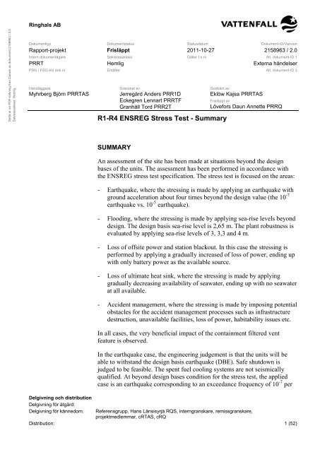
SUMMARY<br />
An assessment of the site has been made at situations beyond the design<br />
bases of the units. The assessment has been performed in accordance with<br />
the <strong>ENSREG</strong> stress test specification. The stress test is focused on the areas:<br />
- Earthquake, where the stressing is made by applying an earthquake with<br />
ground acceleration about four times beyond the design value (the 10 -7<br />
earthquake vs. 10 -5 earthquake).<br />
- Flooding, where the stressing is made by applying sea-rise levels beyond<br />
design. The design basis sea-rise level is 2,65 m. The plant robustness is<br />
evaluated by applying sea-rise levels of 3, 3,3 and 4 m.<br />
- Loss of offsite power and station blackout. In this case the stressing is<br />
performed by applying a gradually increased of loss of power, ending up<br />
with only battery power as the available source.<br />
- Loss of ultimate heat sink, where the stressing is made by applying<br />
gradually decreasing availability of seawater, ending up with no seawater<br />
at all available.<br />
- Accident management, where the stressing is made by imposing potential<br />
obstacles for the accident management processes such as infrastructure<br />
destruction, unavailable facilities, loss of power, habitability issues etc.<br />
In all cases, the very beneficial impact of the containment filtered vent<br />
feature is observed.<br />
In the earthquake case, the engineering judgement is that the units will be<br />
able to withstand the design basis earthquake (DBE). Safe shutdown is<br />
judged to be feasible. The spent fuel cooling systems are not seismically<br />
qualified. At beyond design bases condition for the stress test, the applied<br />
case is an earthquake corresponding to an exceedance frequency of 10 -7 per<br />
Delgivning och distribution<br />
Delgivning för åtgärd:<br />
Delgivning för kännedom: Referensgrupp, Hans Länsisyrjä RQS, interngranskare, remissgranskare,<br />
projektmedlemmar, cRTAS, cRQ<br />
Distribution: 1 (52)
Detta ar en PDF-tolkning fran Darwin av dokument 2158963 / 2.0<br />
Sekretessklass: Hemlig<br />
Dokumentstatus Alt dokument ID 1 Alt dokument ID 2 Dokument ID / Version<br />
Frisläppt Externa händelser 2158963 / 2.0<br />
site and year. At this condition, the containments, the containment filtered<br />
vents, the fuel buildings and the fuel pools and the severe accident mitigation<br />
systems are judged to be able to perform their release preventing functions.<br />
As mentioned above, the spent fuel cooling systems are not seismically<br />
qualified.<br />
In the flooding case, the assessment concludes that for the design basis<br />
flooding, a sea level rise of 2,65 m, no fuel damage will occur. Beyond<br />
design basis, flooding of the units may occur with the potential of causing<br />
fuel damage by elimination of safety functions and spent fuel cooling<br />
equipment. Robustness exists up to the ground level, which is 3 m above sea<br />
level. At a sea-level rise of 4 m fuel damages are judged to be possible.<br />
Addressing the question of an appropriate sea-level rise is required before<br />
relevant measures can be taken.<br />
In the “Loss of offsite power and station blackout” case, the assessment<br />
concludes that the limiting case is when only battery power is available.<br />
Robustness exists as long as anyone of the ordinary backup power sources<br />
(diesel generators or gas turbines) or the steam driven auxiliary feedwater<br />
systems are available. Postulating power system recovery times beyond<br />
design, exhaustion of batteries, depletion of the water sources for the steam<br />
driven systems and operation at low RCS inventory conditions will cause<br />
fuel damage. The containment filtered vent feature will contribute in keeping<br />
the releases within allowable limits. The loss of power will also cause a loss<br />
of the spent fuel cooling.<br />
Addressing the adequacy of the current battery capacities and the availability<br />
of the backup power sources is required before relevant measures can be<br />
taken.<br />
In the case of loss of ultimate heat sink, the assessment concludes that<br />
robustness exists for several days in all cases, with the exception of<br />
operation at low RCS inventory conditions at the PWR’s. Addressing the<br />
operation at low RCS inventory conditions coincident with loss of UHS is<br />
required before relevant measures can be taken.<br />
Regarding accident management, the assessment concludes robustness for<br />
events within design. The beneficial impact of the containment filtered vent<br />
is emphasised. When applying the Fukushima scenario as described in the<br />
stress test specification, a number of shortcomings are displayed. The<br />
emergency response organization can not handle four units simultaneously<br />
affected, the two existing mobile pump/generator units may not be enough,<br />
loss of cooling of the spent fuel pools can not be managed etc. Addressing<br />
the appropriate scenario to be applied is required before relevant measures<br />
can be taken.<br />
The evaluation of the Ringhals site in the light of the Fukushima accident<br />
and in accordance with the <strong>ENSREG</strong> stress test specification has revealed a<br />
number of areas subject to improvement:<br />
- The spent fuel pool cooling abilities needs to be further<br />
evaluated/reinforced<br />
Hemlig 2 (52)
Detta ar en PDF-tolkning fran Darwin av dokument 2158963 / 2.0<br />
Sekretessklass: Hemlig<br />
Dokumentstatus Alt dokument ID 1 Alt dokument ID 2 Dokument ID / Version<br />
Frisläppt Externa händelser 2158963 / 2.0<br />
- The properties of the emergency response organization needs to be<br />
reconsidered<br />
- The flooding scenario needs to be reconsidered<br />
- The requirement for battery capacity is generally an area to analyze<br />
further.<br />
- The adequacy of the present water supplies needs to be reconsidered.<br />
The resulting potential plant improvements within each area are indicated in<br />
the referenced detailed evaluations, and summarized in this report. Before<br />
implementation of the indicated improvements is initiated, further in depth<br />
consideration is required to assure the correctness and suitability and that no<br />
jeopardizing of other plant properties will be caused.<br />
Hemlig 3 (52)
Detta ar en PDF-tolkning fran Darwin av dokument 2158963 / 2.0<br />
Sekretessklass: Hemlig<br />
Dokumentstatus Alt dokument ID 1 Alt dokument ID 2 Dokument ID / Version<br />
Frisläppt Externa händelser 2158963 / 2.0<br />
R E V I D E R I N G S F Ö R T E C K N I N G<br />
Version<br />
Nr.<br />
Reviderade<br />
sidor<br />
Orsak<br />
Handläggare/<br />
Frisläppt av<br />
2.0 Första utgåvan B Myhrberg/<br />
A Lövefors<br />
Hemlig 4 (52)
Detta ar en PDF-tolkning fran Darwin av dokument 2158963 / 2.0<br />
Sekretessklass: Hemlig<br />
Dokumentstatus Alt dokument ID 1 Alt dokument ID 2 Dokument ID / Version<br />
Frisläppt Externa händelser 2158963 / 2.0<br />
INNEHÅLLSFÖRTECKNING<br />
1 INTRODUCTION ........................................................................................8<br />
1.1 <strong>Stress</strong> test background information........................................................8<br />
1.2 Evaluation method of plant robustness ..................................................8<br />
1.3 Previous reporting during the process ...................................................9<br />
1.4 Other assessments of the incident..........................................................9<br />
1.5 Scope of the stress test............................................................................9<br />
2 SITE DESCRIPTION ................................................................................10<br />
2.1 The site ....................................................................................................10<br />
2.1.1 Hydrological characteristics ......................................................................10<br />
2.1.2 Seismological characteristics ....................................................................11<br />
2.1.3 Exposure to air transportation events........................................................11<br />
2.2 Applicability of the ENREG accessibility limitations of 24 hours<br />
respectively 72 hours .............................................................................11<br />
2.3 Basic design of the plants......................................................................13<br />
2.3.1 Ringhals 1 characteristics .........................................................................14<br />
2.3.2 Ringhals 2 characteristics .........................................................................14<br />
2.3.3 Ringhals 3 characteristics .........................................................................14<br />
2.3.4 Ringhals 4 characteristics .........................................................................14<br />
2.4 Safety significant differences ................................................................14<br />
2.5 Defence in depth principle .....................................................................16<br />
2.6 The containment filtered vent feature ...................................................20<br />
2.7 Performed safety enhancements...........................................................23<br />
2.8 Routine safety enhancement work ........................................................24<br />
2.9 Scope and results of PSA ......................................................................24<br />
2.9.1 Scope .......................................................................................................24<br />
2.9.2 Ringhals 1.................................................................................................24<br />
2.9.3 Ringhals 2.................................................................................................26<br />
2.9.4 Ringhals 3.................................................................................................27<br />
2.9.5 Ringhals 4.................................................................................................29<br />
3 STRESSTEST RESULTS.........................................................................30<br />
3.1 Earthquake ..............................................................................................30<br />
3.2 Flooding ..................................................................................................32<br />
3.3 Loss of offsite power (LOOP) and station blackout (SBO) ..................34<br />
3.4 Loss of ultimate heat sink without/with SBO........................................41<br />
3.4.1 Loss of ultimate heat sink without SBO.....................................................41<br />
3.4.2 Loss of ultimate heat sink with SBO..........................................................44<br />
3.5 Accident management............................................................................44<br />
4 SUMMARY ASSESSMENT......................................................................48<br />
Hemlig 5 (52)
Detta ar en PDF-tolkning fran Darwin av dokument 2158963 / 2.0<br />
Sekretessklass: Hemlig<br />
Dokumentstatus Alt dokument ID 1 Alt dokument ID 2 Dokument ID / Version<br />
Frisläppt Externa händelser 2158963 / 2.0<br />
5 AREAS SUBJECT TO IMPROVEMENTS ................................................50<br />
6 REFERENCES .........................................................................................51<br />
Hemlig 6 (52)
Detta ar en PDF-tolkning fran Darwin av dokument 2158963 / 2.0<br />
Sekretessklass: Hemlig<br />
Dokumentstatus Alt dokument ID 1 Alt dokument ID 2 Dokument ID / Version<br />
Frisläppt Externa händelser 2158963 / 2.0<br />
LIST OF ABBREVIATIONS<br />
DBE<br />
CFV<br />
RCS<br />
PWR<br />
BWR<br />
Design Bases Earthquake<br />
Containment Filtered Vent<br />
Reactor Coolant System<br />
Pressurized Water Reactor<br />
Boiling Water Reactor<br />
<strong>ENSREG</strong> European Nuclear Safety Regulators<br />
SAR<br />
TMI<br />
WANO<br />
SOER<br />
LOOP<br />
Safety Analysis Report<br />
Three Mile Island<br />
World Association of Nuclear Operators<br />
Significant Operating Experience Report<br />
Loss of Offsite Power<br />
OPS Original Plant Section (Ringhals unit 1)<br />
DPS Diversified Plant Section (Ringhals unit 1)<br />
SBO<br />
UHS<br />
ICS<br />
PGA<br />
CRDM<br />
DBF<br />
Station Blackout<br />
Ultimate Heat Sink<br />
Independent Containment Spray<br />
Peak Ground Acceleration<br />
Control Rod Drive Mechanism<br />
Design Bases Flooding<br />
Hemlig 7 (52)
Detta ar en PDF-tolkning fran Darwin av dokument 2158963 / 2.0<br />
Sekretessklass: Hemlig<br />
Dokumentstatus Alt dokument ID 1 Alt dokument ID 2 Dokument ID / Version<br />
Frisläppt Externa händelser 2158963 / 2.0<br />
1 INTRODUCTION<br />
1.1 <strong>Stress</strong> test background information<br />
On the 25th of March 2011, the European Council of Ministers declared that<br />
the safety of all EU nuclear plants should be reviewed on the basis of<br />
comprehensive and transparent risk and safety assessments (“stress tests”) as<br />
a consequence of the Fukushima accident. The organization <strong>ENSREG</strong><br />
(European Nuclear Safety Regulators Group), which is an expert body,<br />
composed of senior officials from national regulatory or nuclear safety<br />
authorities from all 27 member states in the EU, has thereafter agreed on the<br />
criteria for how the stress tests should be performed.<br />
The report at hand is a summary of Ringhals AB’s answer to the Swedish<br />
Radiation Safety Authority’s injunction ”Förnyade säkerhetsvärderingar av<br />
tålighet mot vissa händelser” [7], which states that Ringhals AB must<br />
perform the <strong>ENSREG</strong> stress test for all its units. The stress test specification<br />
is found in Appendix 2 in [7].<br />
1.2 Evaluation method of plant robustness<br />
Nuclear power plants are designed with large safety margins. The safety<br />
margins are related to a number of postulated events, such as pipe breaks in<br />
the primary system, steam line break, flooding, wind etc. The plants are<br />
designed to withstand these postulated conditions with satisfactory margins.<br />
At the stress test according to <strong>ENSREG</strong>, the plant properties at conditions<br />
beyond the postulated design conditions are evaluated. This will result in an<br />
evaluation of to what extent the plant can withstand conditions beyond<br />
design without fuel damage occurring.<br />
The stress test principle is that the plant safety functions gradually are<br />
assumed to fail, regardless of redundancy properties. This will finally display<br />
a level of degradation where fuel damage is unavoidable.<br />
The stress test specification frequently addresses the point at which “fuel<br />
damage is unavoidable”. In the evaluations this point generally is when the<br />
core exit thermocouples indicate 650C (PWR) or the water level has<br />
decreased to the top of the core (BWR). In some cases, emptying of water<br />
sources is applied as criteria, however somewhat conservative. Concerning<br />
fuel pool discussions, the point is applied as the point when the water level<br />
has decreased to the top of the fuel assemblies.<br />
The base for the evaluation is the current unit analyses in the SAR’s,<br />
supplemented by descriptive discussions and engineering judgements where<br />
we are beyond the scope of the SAR.<br />
The stress test according to the <strong>ENSREG</strong> specification has an endpoint when<br />
fuel damage is unavoidable. However, the Swedish plants are designed to<br />
cope with a scenario even after severe fuel damage and vessel melt-through<br />
Hemlig 8 (52)
Detta ar en PDF-tolkning fran Darwin av dokument 2158963 / 2.0<br />
Sekretessklass: Hemlig<br />
Dokumentstatus Alt dokument ID 1 Alt dokument ID 2 Dokument ID / Version<br />
Frisläppt Externa händelser 2158963 / 2.0<br />
has occurred. This scenario, the containment filtered vent scenario, was<br />
introduced at the Swedish plants in 1988 in accordance with government<br />
decision 11, 1986 [27]. The purpose of this government decision, derived<br />
from the TMI accident, was among others to prevent a ground deposition at<br />
severe accidents that in the long term will prevent the utilization of extensive<br />
land areas. The containment filtered vent feature is described in section 2.6.<br />
1.3 Previous reporting during the process<br />
The evaluation of the units according to the <strong>ENSREG</strong> stress test<br />
specification was initiated by the regulator SSM via the injunction<br />
2011/2065, ”Förnyade säkerhetsvärderingar av tålighet mot vissa händelser ”<br />
[7].<br />
The prerequisites for the stress test was reported by Ringhals AB in 2011-06-<br />
08 [8], additional prerequisites were reported 2011-07-12 [9]. The<br />
prerequisites were reviewed by SSM in a review report 2011-07-29 [10].<br />
The progress of the work was reported to SSM in 2011-08-15 [11],<br />
contributing to the national progress report submitted to the EU in 2011-09-<br />
15.<br />
1.4 Other assessments of the incident<br />
Shortly after the accident, the regulator SSM emphasized the importance of<br />
initiating plant specific evaluations, aimed at identifying potential<br />
reinforcements [12]. A dedicated project was established within the Ringhals<br />
site organization [13]. This project was later adapted to the requirements of<br />
the regulatory injunction [7].<br />
The WANO SOER’s 2011-2 and 2011-3 are addressed within the site<br />
organization.<br />
WANO SOER 2011-2, Fukushima Daiichi Nuclear station fuel damage<br />
caused by earthquake and tsunami, was addressed and reported [30].<br />
WANO SOER 2011-3, Fukushima Daiichi Nuclear station spent fuel<br />
pool/pond loss of cooling and makeup, is being addressed at the moment.<br />
1.5 Scope of the stress test<br />
The extent of the stress test according to the <strong>ENSREG</strong> specification results<br />
in an evaluation of the plant in the following perspectives:<br />
- The earthquake perspective, meaning that an evaluation is performed by<br />
applying an earthquake more severe than the design earthquake. The<br />
plant possibilities to fulfil the release preventing functions at theses<br />
conditions are evaluated.<br />
- The flooding perspective, meaning that an evaluation is performed of the<br />
magnitude of a flooding the plant can withstand before fuel damage is<br />
unavoidable.<br />
Hemlig 9 (52)
Detta ar en PDF-tolkning fran Darwin av dokument 2158963 / 2.0<br />
Sekretessklass: Hemlig<br />
Dokumentstatus Alt dokument ID 1 Alt dokument ID 2 Dokument ID / Version<br />
Frisläppt Externa händelser 2158963 / 2.0<br />
- The loss of power perspective, meaning that an evaluation is performed<br />
of the plant long term properties during a gradual loss of power sources<br />
until only battery power remains. The available range of time until fuel<br />
damage is unavoidable is evaluated.<br />
- The ultimate heat sink perspective, meaning that an evaluation is<br />
performed of the plant long term properties during a gradual loss of sea<br />
water for plant cooling. The available range of time until fuel damage is<br />
unavoidable is evaluated.<br />
- The accident management perspective, meaning that an evaluation is<br />
performed of the adequacy of the accident management procedures, and<br />
of the emergency response organization.<br />
A common feature of the evaluations is that potential cliff-edge effects are<br />
identified. Cliff-edge effects may be e.g. exhaustion of batteries, lack of<br />
diesel fuel, emptied water supplies etc. A cliff edge effect causes the<br />
sequence of events to change in a significant way, and based on this, areas<br />
subject to improvements, further evaluations or reinforcements can be<br />
identified.<br />
The stress test specification frequently addresses the point at which “fuel<br />
damage is unavoidable”. In the evaluations this point is defined as when the<br />
core exit thermocouples indicate 650C (PWR) or the water level has<br />
decreased to the top of the core (BWR). Concerning fuel pool discussions,<br />
the point is defined as the point when the water level has decreased to the top<br />
of the fuel elements.<br />
2 SITE DESCRIPTION<br />
2.1 The site<br />
The Ringhals plant is situated along the west coast of Sweden on the Värö<br />
peninsula within the Varberg municipality in the province of Halland.<br />
Contiguous cities are Varberg 25 km south of and Gothenburg 60 km north<br />
of Ringhals.<br />
The site has four units, one BWR and three PWR’s. The site is operated by<br />
Ringhals AB, who is the license holder.<br />
2.1.1 Hydrological characteristics<br />
The site is situated by the sea, and is consequently exposed to events<br />
originating from the sea. In the vicinity of the site, there are no dams or<br />
rivers constituting potential sources of flooding. The single source of<br />
flooding with the potential to cause a sequence of events resulting in fuel<br />
damage is a sea-level rise.<br />
The assumed highest flooding level is a sea level rise of 2,65 m [3].<br />
Tsunami<br />
Hemlig 10 (52)
Detta ar en PDF-tolkning fran Darwin av dokument 2158963 / 2.0<br />
Sekretessklass: Hemlig<br />
Dokumentstatus Alt dokument ID 1 Alt dokument ID 2 Dokument ID / Version<br />
Frisläppt Externa händelser 2158963 / 2.0<br />
A tsunami is created by seismic events or underwater landslides.<br />
During an underwater earthquake a large amount of energy is added to the<br />
water. Since these events often occurs in the Pacific at large depths, the<br />
energy addition does not result in a significant level increase in the open sea.<br />
The result is a minor level increase of 0,5 – 1 m moving at large velocity<br />
away from the area. The energy is transmitted as a long wave, at the velocity<br />
C = (g * h) 1/2 ,<br />
Where the depth h often is of the magnitude 4000m. This results in a wave<br />
velocity of » 200 m/s (700 km/h). When reaching the shore the wave will be<br />
retarded by the decreasing depth, resulting in an increasing height.<br />
In the seas surrounding Sweden no tsunami has been registered. Even if<br />
tsunami initiating events should occur, the impact would be small since the<br />
depth of the surrounding sea is limited. The average depth in the Baltic is 60<br />
m and is assumed to be similar in the Kattegatt, resulting in a wave velocity<br />
of 25 m/s. This concludes that the waves will not generate any larger waves<br />
with the potential to cause any major damage [18].<br />
Tide<br />
Water level variations due to tide are usually insignificant, but may add up to<br />
an extra 30 cm to the water level variations due to atmospheric pressure and<br />
wind load [18].<br />
2.1.2 Seismological characteristics<br />
In Scandinavia seismic activity is generally low. The region is generally<br />
considered as being seismically stable. Only a few incidents have been<br />
registered in historic time, which might have damaged an industrial plant of<br />
today. The risk of a nuclear accident in Sweden, caused by an Earthquake,<br />
may thus be considered to be low. The bedrock conditions at the site are<br />
further discussed in [20]<br />
The design basis earthquake is an earthquake with the occurrence frequency<br />
of 10 -5 /year [21].<br />
2.1.3 Exposure to air transportation events<br />
The probability of an airplane incident in the vicinity of the Ringhals site is<br />
estimated to be very low, 2E-8 [22]. The air transportation is further<br />
discussed in [29].<br />
2.2 Applicability of the ENREG accessibility limitations of 24 hours<br />
respectively 72 hours<br />
In the <strong>ENSREG</strong> document a footnote states that:<br />
Hemlig 11 (52)
Detta ar en PDF-tolkning fran Darwin av dokument 2158963 / 2.0<br />
Sekretessklass: Hemlig<br />
Dokumentstatus Alt dokument ID 1 Alt dokument ID 2 Dokument ID / Version<br />
Frisläppt Externa händelser 2158963 / 2.0<br />
“All offsite electric power supply to the site is lost. The offsite power should<br />
be assumed to be lost for several days. The site is isolated from delivery of<br />
heavy material for 72 hours by road, rail or waterways. Portable light<br />
equipment can arrive to the site from other locations after the first 24 hours.”<br />
Application of the stated timeframes of 24 respectively 72 hours requires is<br />
required to be further motivated.<br />
Within the site, it has to be credible that the generated amount of debris in<br />
the plant yard can be handled in such a way that transportation activities are<br />
possible.<br />
In order to credit portable light equipment after the first 24 hours, access to<br />
the site area has to be made credible, i.e snow obstacles and other obstacles<br />
should be made credible to be removed. Further, the assessed light<br />
equipment, has to be available within transportation range. Light equipment<br />
is assumed to be equipment transportable by off road vehicles or<br />
bandwagons.<br />
In order to credit heavy material first 72 hours, access to the site area has to<br />
be made credible, i.e snow obstacles and other obstacles should be made<br />
credible to be removed. Further, the assessed heavy material, has to be<br />
available within transportation range. Heavy material is basically assumed to<br />
be equipment requiring truck transportation by road.<br />
The site organisation capabilities regarding clearance of the site area in case<br />
of bad weather conditions or other events is managed by the on shift rescue<br />
team. At their disposal, the team has a fully equipped fire truck and an off<br />
road vehicle. At emergency situations, the site heavy vehicles such as front<br />
loaders and lifting trucks are also available. Based on the presence of the on<br />
shift rescue team and the available equipment, it is judged that the site area<br />
can be cleared for transportation purposes within 24 hours following bad<br />
weather conditions or other events.<br />
The transportation possibilities by road at bad weather or other difficult<br />
situations are managed by Trafikverket (Department of Transportation) and<br />
its local subcontractors. The experiences from previous bad weather<br />
conditions is that the roads are cleared well within 24 hours. Should the<br />
situation reach a societal emergency level, the First Commander of Rescue<br />
Service disposes all of the resources of the society.<br />
Based on the experience of historical bad weather situations, and the<br />
availability of the total society resources in emergency situations, it is<br />
reasonable to site specifically apply the timeframes of 24 hours respectively<br />
72 hours as described in the footnote of the <strong>ENSREG</strong> document.<br />
Hemlig 12 (52)
Detta ar en PDF-tolkning fran Darwin av dokument 2158963 / 2.0<br />
Sekretessklass: Hemlig<br />
Dokumentstatus Alt dokument ID 1 Alt dokument ID 2 Dokument ID / Version<br />
Frisläppt Externa händelser 2158963 / 2.0<br />
2.3 Basic design of the plants<br />
The plants are designed to confine the radioactive material by physical<br />
barriers. There are dedicated systems intended to protect and maintain these<br />
barriers.<br />
The barriers are the fuel pellet structure, the fuel cladding, the reactor<br />
coolant pressure boundary and the containment.<br />
The protective functions included in the plant design in order to maintain the<br />
barrier integrity are characterized of design according to the single failure<br />
criterion, i.e. one single failure in the protective function does not jeopardize<br />
the purpose of the function.<br />
The plants were originally designed with two main trains of safety functions.<br />
The supporting power system was divided into four sub trains, each one with<br />
a dedicated emergency diesel generator. Two sub trains are supporting each<br />
main train.<br />
The two train design has during the years been reinforced. Additional reactor<br />
trip systems have been installed on all units. On Ringhals 1 an entire diverse<br />
plant section (DPS) has been installed in addition to the original plant section<br />
(OPS). Measures to strengthen the physical and functional separation of the<br />
trains have been taken.<br />
The parallel trains may in some cases perform the intended functions by<br />
different methods such as steam driven and motor driven pumps,<br />
diversification.<br />
The plant is designed to protect the barriers with automatically taken<br />
measures or by permitting reasonable time for consideration of manual<br />
actions. The latter is often called "Grace time" or "Time for reflection".<br />
All units are equipped with steam driven systems to provide core cooling<br />
capabilities, either directly to the reactor vessel (BWR) or via the steam<br />
generators (PWR).<br />
The power supply to the unit during normal operation consists of two<br />
alternative sources; the national 400 kV grid and the national 130 kV grid.<br />
At accident conditions, the power is supplied by four dedicated diesel<br />
generators and gas turbine plant common for the site. Ringhals 1 has in<br />
addition to this another two air cooled diesel generators installed within the<br />
diversified plant section. The unit is also equipped with house load operation<br />
feature, according to the national grid requirements. Furthermore, an<br />
additional full capacity mobile diesel generator is available at the site. The<br />
power supply to the filtered vent systems has independent battery capacity<br />
and a dedicated mobile generator set.<br />
The spent fuel is stored in the spent fuel pools at the unit for an average time<br />
of one year, prior to transportation to the national spent fuel storage facility.<br />
Hemlig 13 (52)
Detta ar en PDF-tolkning fran Darwin av dokument 2158963 / 2.0<br />
Sekretessklass: Hemlig<br />
Dokumentstatus Alt dokument ID 1 Alt dokument ID 2 Dokument ID / Version<br />
Frisläppt Externa händelser 2158963 / 2.0<br />
2.3.1 Ringhals 1 characteristics<br />
Ringhals 1 is an ASEA-Atom design BWR with a rated thermal power of<br />
2540 MW. The first criticality was achieved by august 20, 1973.<br />
2.3.2 Ringhals 2 characteristics<br />
Ringhals 2 is a Westinghouse design three loop PWR with a rated thermal<br />
power of 2660 MW. The first criticality was achieved by June 19, 1974.<br />
2.3.3 Ringhals 3 characteristics<br />
Ringhals 3 is a Westinghouse design three loop PWR with a rated thermal<br />
power of 3151 MW. The first criticality was achieved by July 29, 1980.<br />
2.3.4 Ringhals 4 characteristics<br />
Ringhals 4 is a Westinghouse design three loop PWR with a rated thermal<br />
power of 2783 MW. The first criticality was achieved by May 19, 1982.<br />
2.4 Safety significant differences<br />
The safety significant properties and differences regarding the areas of the<br />
stress test scope (earthquake, flooding, LOOP/SBO, UHS, severe accident<br />
management) are discussed below.<br />
All units are finalising programs to improve the safety of the plants as<br />
requested in regulations that have been implemented for that purpose<br />
(SSMFS 2008:17). These requirements encompass the ability of the units to<br />
cope with external events.<br />
Earthquake<br />
With regard to the safety properties during earthquake conditions, there are<br />
no significant structural differences between the units.<br />
The four units at the site are exposed to the same seismic conditions.<br />
Originally, the units were not designed with seismic considerations since<br />
Sweden is a zone with low seismic activity.<br />
The modern national regulations require seismic upgrading of the units,<br />
which is an ongoing work.<br />
The BWR unit is divided into two parts regarding the safety features, OPS<br />
(Original Plant Section) and DPS (Diverse Plant Section), where the DPS is<br />
seismically qualified.<br />
The I&C-system on Ringhals 2 was recently replaced and seismically<br />
qualified.<br />
Hemlig 14 (52)
Detta ar en PDF-tolkning fran Darwin av dokument 2158963 / 2.0<br />
Sekretessklass: Hemlig<br />
Dokumentstatus Alt dokument ID 1 Alt dokument ID 2 Dokument ID / Version<br />
Frisläppt Externa händelser 2158963 / 2.0<br />
The essential safety feature with regard to radioactive releases, the filtered<br />
vent of the containments, was originally designed with seismic<br />
considerations.<br />
Flooding<br />
With regard to the safety properties at flooding conditions, there are no<br />
significant differences between the units.<br />
The four units are erected at the same ground level, 3 meters above sea level,<br />
and are consequently equally exposed to flooding. Other potential flooding<br />
sources such as dams or rivers do not exist in the vicinity of the site.<br />
Loss of offsite power/Station blackout (LOOP/SBO)<br />
With regard to the safety properties at LOOP/SBO conditions, there are<br />
differences between the units.<br />
All units are equipped with four diesel generators, supplying redundant<br />
equipment. The durability of the diesel generators is further discussed in the<br />
LOOP section of the report.<br />
Ringhals 1 is further equipped with two additional diesel generators,<br />
supplying the DPS. (At Ringhals 1, a physically and functionally separated<br />
and diversified reactor protection system called DPS (Diversified Plant<br />
Section) has been installed. The DPS works in parallel with the Original<br />
Plant Section, OPS.)<br />
All units have steam driven systems supplying cooling capacity at loss of<br />
power situations.<br />
All units are supplied with battery capacity for the SBO case. The durability<br />
of the batteries is further discussed in the SBO section of the report.<br />
Ultimate Heat Sink (UHS)<br />
With regard to the safety properties of the UHS, there are no significant<br />
differences between the units.<br />
The UHS is the sea. The seawater canal system is similar for all units.<br />
The properties of the seawater canal system are further discussed in the UHS<br />
section of the report.<br />
Severe accident management<br />
With regard to severe accident management, there is no significant difference<br />
between the units.<br />
Hemlig 15 (52)
Detta ar en PDF-tolkning fran Darwin av dokument 2158963 / 2.0<br />
Sekretessklass: Hemlig<br />
Dokumentstatus Alt dokument ID 1 Alt dokument ID 2 Dokument ID / Version<br />
Frisläppt Externa händelser 2158963 / 2.0<br />
The severe accident management is based on the presence of the filtered vent<br />
feature of the units. The severe accident scenario resulting in a reactor vessel<br />
melt-through trained in similar ways for the BWR and the PWR’s.<br />
The accident management organisation is common for the site.<br />
2.5 Defence in depth principle<br />
As described above the plants are designed with the safety objective of<br />
confining the radioactive material by physical barriers, maintained by<br />
dedicated protective systems and the management of the plant. This<br />
philosophy is described in the defence in depth principle.<br />
In order to meet the principal safety objectives, the concept of defence in<br />
depth is one of the most fundamental principles guiding the design of the<br />
plant and the principles for administrative control of the operation, providing<br />
an overall strategy for safety measures and features of nuclear power plants.<br />
When properly applied, the defence in depth concept ensures that no single<br />
human or equipment failure would lead to harm to the public, and even<br />
combinations of failures that are improbable would lead to little or no harm.<br />
Defence in depth helps to establish that the basic safety functions;<br />
- Controlling the power,<br />
- Cooling the fuel, and<br />
- Confining radioactive material,<br />
are preserved, and that radioactive material do not reach people or the<br />
environment.<br />
The principle of defence in depth is implemented primarily by means of a<br />
series of barriers which would in principle never be jeopardized, and which<br />
must be violated in turn before harm can occur to people or the environment.<br />
These barriers are physical, providing for the confinement of radioactive<br />
materials at successive locations.<br />
The concept of defence in depth, as applied to all safety activities, whether<br />
organizational, behavioural or design related, ensures that they are subject to<br />
overlapping provisions, so that if a failure were to occur, it would be<br />
detected and compensated for or corrected by appropriate measures.<br />
Application of the defence in depth concept throughout design and operation<br />
provides a graded protection against a wide variety of transients, anticipated<br />
operational occurrences and accidents, including those resulting from<br />
equipment failure of human action within the plant, and events that originate<br />
outside the plant.<br />
With the publication of INSAG-3, 1988 five levels, as presented in the list<br />
below, were defined<br />
Hemlig 16 (52)
Detta ar en PDF-tolkning fran Darwin av dokument 2158963 / 2.0<br />
Sekretessklass: Hemlig<br />
Dokumentstatus Alt dokument ID 1 Alt dokument ID 2 Dokument ID / Version<br />
Frisläppt Externa händelser 2158963 / 2.0<br />
Levels of<br />
defence in<br />
depth<br />
Level 1<br />
Level 2<br />
Level 3<br />
Level 4<br />
Level 5<br />
Objective<br />
Prevention of abnormal operation and<br />
failures<br />
Control of abnormal operation and<br />
detection of failures<br />
Control of accidents within the design<br />
basis<br />
Control of severe plant conditions,<br />
including prevention of accident<br />
progression and mitigation of the<br />
consequences of severe accidents<br />
Mitigation of radiological consequences<br />
of significant releases of radioactive<br />
materials<br />
Essential means<br />
Conservative design and high<br />
quality in construction and<br />
operation<br />
Control, limiting and<br />
protection systems and other<br />
surveillance features<br />
Engineered safety features and<br />
accident procedures<br />
Complementary measures and<br />
accident management<br />
Off-site emergency response<br />
Application of the concept of defence in depth in the design of the plant<br />
provides a series of levels of defence (inherent features, equipment and<br />
procedures) aimed at preventing accidents and ensuring appropriate<br />
protection in the event that prevention fails.<br />
The aim of the first level of defence is to prevent deviations from normal<br />
operation. This leads to the requirement that the plant should be soundly and<br />
conservatively designed, constructed, maintained and operated in accordance<br />
with appropriate quality levels and engineering practices, such as the<br />
application of redundancy, independence and diversity in order prevent<br />
equipment failures.<br />
The aim of the second level of defence is to detect and intercept deviations<br />
from normal operational states in order to prevent anticipated operational<br />
occurrences from escalating to accident conditions. This is in recognition of<br />
the fact that some postulated initiating events are likely to occur over the<br />
service lifetime of a nuclear power plant, despite the care taken to prevent<br />
them. This level necessitates the provision of specific systems as determined<br />
in the safety analysis and the definition of operating procedures to prevent or<br />
minimize damage from such postulated initiating events.<br />
For the third level of defence, it is assumed that, although very unlikely, the<br />
escalation of certain anticipated operational occurrences or postulated<br />
initiating events may not be arrested by a preceding level and a more serious<br />
event may develop. These unlikely events are anticipated in the design basis<br />
for the plant, and inherent safety features, fail-safe design, additional<br />
equipment and procedures are provided to control their consequences and to<br />
achieve stable and acceptable plant states following such events. This leads<br />
Hemlig 17 (52)
Detta ar en PDF-tolkning fran Darwin av dokument 2158963 / 2.0<br />
Sekretessklass: Hemlig<br />
Dokumentstatus Alt dokument ID 1 Alt dokument ID 2 Dokument ID / Version<br />
Frisläppt Externa händelser 2158963 / 2.0<br />
to the requirement that engineered safety features be provided that are<br />
capable of leading the plant first to a controlled state, and subsequently to a<br />
safe shutdown state, and maintaining at least one barrier for the confinement<br />
of radioactive material.<br />
The aim of the fourth level of defence is to address severe accidents in which<br />
the design basis may be exceeded and to ensure that radioactive releases are<br />
kept as low as practicable. The most important objective of this level is the<br />
protection of the confinement function. This may be achieved by<br />
complementary measures and procedures to prevent accident progression,<br />
and by mitigation of the consequences of selected severe accidents, in<br />
addition to accident management procedures. The protection provided by the<br />
confinement may be demonstrated using best estimate methods.<br />
The fifth and final level of defence is aimed at mitigation of the radiological<br />
consequences of potential releases of radioactive materials that may result<br />
from accident conditions. This requires the provision of an adequately<br />
equipped emergency control center, and plans for the on-site and off-site<br />
emergency response.<br />
A relevant aspect of the implementation of defence in depth is the provision<br />
in the design of a series of physical barriers to confine the radioactive<br />
material at specified locations. The number of necessary physical barriers<br />
depends on the potential internal and external hazards, and the potential<br />
consequences of failures. Interaction between the defence in depth concept<br />
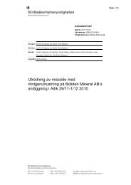
and the barrier concept can be illustrated with the following figure.<br />
Hemlig 18 (52)
Detta ar en PDF-tolkning fran Darwin av dokument 2158963 / 2.0<br />
Sekretessklass: Hemlig<br />
Dokumentstatus Alt dokument ID 1 Alt dokument ID 2 Dokument ID / Version<br />
Frisläppt Externa händelser 2158963 / 2.0<br />
Fig 2-1, Defence in depth vs barriers<br />
Hemlig 19 (52)
Detta ar en PDF-tolkning fran Darwin av dokument 2158963 / 2.0<br />
Sekretessklass: Hemlig<br />
Dokumentstatus Alt dokument ID 1 Alt dokument ID 2 Dokument ID / Version<br />
Frisläppt Externa händelser 2158963 / 2.0<br />
2.6 The containment filtered vent feature<br />
A common characteristic of the units is the containment filtered vent feature.<br />
<strong>R1</strong>-<strong>R4</strong> started commercial operation 1975-1983 and were designed a decade<br />
earlier, with a clear focus at prevention of core damage (i.e. level 1-3 of the<br />
defence in depth principle). Due to the TMI-2 accident 1979 the interest for<br />
mitigating actions increased (i.e. level 4-5 of the defence in depth principle)<br />
and as a result some mitigating systems were implemented in Ringhals in the<br />
late 1980:s:<br />
- Containment Filtered Vent (CFV, system 362)<br />
- Independent Containment Spray (ICS, system 367/365 injecting via<br />
system 322)<br />
The filtered containment venting feature was installed in the Swedish power<br />
plants as a result of new requirements stipulated by the Swedish government.<br />
The Ringhals specific requirement is referred to as “Regeringsbeslut 11,<br />
1986” [27].<br />
The design requirements of the filtered vent are i.a (according to<br />
regeringsbeslut 11)<br />
- In the case of core damage, prepared plant specific strategies shall exist<br />
in order to protect the reactor containment function and to reach a stable<br />
condition where the core is cooled and covered by water.<br />
- It is vital that the reactor containment function remains intact during the<br />
first 10 to 15 hours after a core damage.<br />
- In order to protect the reactor containment against damage from<br />
overpressure during severe accident events, a controlled depressurization<br />
of the reactor containment shall be feasible. The pressure relief devices<br />
shall be independent of operator actions and independent of other safety<br />
systems. The pressure relief devices shall also be possible to operate by<br />
the operators.<br />
- The releases shall be limited to maximum 0.1 % of the reactor core<br />
content of cesium-134 and cesium-137 in a reactor core of 1800 MW<br />
thermal power, provided that other nuclides of significance, from the use<br />
of land viewpoint, are limited to the same extent as cesium.<br />
The chosen design scenario is station blackout (SBO, loss of all AC) and loss<br />
of steam-driven pumps, with no manual actions credited during the first 8<br />
hours. Without actions or mitigating systems such a scenario will typically<br />
give serious core degradation within 1-2 hours, vessel failure within 2-4<br />
hours followed by containment overpressurization and somewhat later gross<br />
failure of containment with large releases of fission products, unless<br />
mitigating measures are taken.<br />
Hemlig 20 (52)
Detta ar en PDF-tolkning fran Darwin av dokument 2158963 / 2.0<br />
Sekretessklass: Hemlig<br />
Dokumentstatus Alt dokument ID 1 Alt dokument ID 2 Dokument ID / Version<br />
Frisläppt Externa händelser 2158963 / 2.0<br />
The requirement is to mitigate the design scenario so that the release of<br />
134 Cs and 137 Cs will be no more than corresponding to 0.1% of the core<br />
inventory of a 1800 MW th core.<br />
After 8 hours the ICS is assumed to be available, which will reduce the containment<br />
pressure and temporarily terminate the filtered release (or delay the<br />
initiation).<br />
In the design scenario for BWR (<strong>R1</strong>) the pressure in the containment will not<br />
reach the design pressure within 8 hours, why the actuation of ICS at this<br />
time will significantly delay the overpressurization of the containment until<br />
more than 24 hours. Somewhat later at a certain pressure the CFV is assumed<br />
to be actuated manually, but in case of no manual actions the CFV will be<br />
automatically actuated through the bursting of a rupture disk.<br />
In the design scenario for PWR (R2-<strong>R4</strong>), the pressure in the containment typically<br />
will reach the design pressure after 4-6 hours. Since no manual<br />
actions are credited during the first 8 hours the CFV will be automatically<br />
actuated through the bursting of a rupture disk and will reduce the<br />
containment pressure through a filtered release. After 8 hours the ICS is<br />
available which will reduce containment pressure and terminate the current<br />
CFV-release.<br />
However, (for both BWR and PWR) if no other means of cooling of the containment<br />
becomes available the ICS injection cannot continue “forever” since<br />
it will fill up the containment and has to be terminated at a certain level after<br />
approximately 30 hours. The pressure will then rise and there will be repeated<br />
activations of the CFV with an energy balance established with “feedand-boil”<br />
with the ICS intermittently injecting water and the CFV dissipating<br />
energy through a filtered release of steam.<br />
The possibility to passively (no operator decision required) prevent a<br />
containment over-pressurization is an important feature when answering the<br />
<strong>ENSREG</strong> questions about protecting containment integrity.<br />
All plants have chosen the FILTRA/MVSS concept to fulfill the<br />
requirements.<br />
FILTRA/MVSS stands for Filtered Containment Venting – Multi Venturi<br />
Scrubber System. The major component is a scrubber system comprising a<br />
large number of small venturi scrubbers submerged in a water pool. A<br />
venturi scrubber is a gas cleaning device that relies on the passage of the gas<br />
through a fine mist of water droplets. The design of the venturis is based<br />
upon the suppliers wide experience in this area gained in designing venturis<br />
for cleaning polluted gases from various industrial plants.<br />
Separation of aerosols and gaseous iodine takes place in the venturis and the<br />
radioactive matter is transferred to the pool water.<br />
Since the venturis are located on different levels and are sealed off by the<br />
internal water level, the number of engaged venturis is proportional to the<br />
pressure in the containment and thereby the total relief flow. Consequently,<br />
each venturi always operate close to the optimal flow and high<br />
Hemlig 21 (52)
Detta ar en PDF-tolkning fran Darwin av dokument 2158963 / 2.0<br />
Sekretessklass: Hemlig<br />
Dokumentstatus Alt dokument ID 1 Alt dokument ID 2 Dokument ID / Version<br />
Frisläppt Externa händelser 2158963 / 2.0<br />
decontamination factors are therefore achieved over a wide flow range. The<br />
activation of venturis is inherently automatic and no external flow control is<br />
required.<br />
A moisture separator collects the entrained pool water droplets efficiently.<br />
The basic design requirement in Sweden was that depressurization of the<br />
reactor containment shall be possible without relying on operator action. This<br />
required activation by means of a rupture disc and efficient separation over a<br />
very wide flow range. Further, a sturdy design operating at low pressure was<br />
preferred, in order not to have the filter function jeopardized by dynamic<br />
effects such as hydrogen explosions.<br />
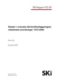
A principal figure of the filter is shown below.<br />
Fig 2-1, Containment filtered vent principal design<br />
A = Pressure relief line<br />
from the containment<br />
D = Pool<br />
G = Pressure vessel<br />
B = Venturi distribution E = Moisture H = Manhole<br />
Hemlig 22 (52)
Detta ar en PDF-tolkning fran Darwin av dokument 2158963 / 2.0<br />
Sekretessklass: Hemlig<br />
Dokumentstatus Alt dokument ID 1 Alt dokument ID 2 Dokument ID / Version<br />
Frisläppt Externa händelser 2158963 / 2.0<br />
system<br />
C = Venturis including<br />
riser pipe<br />
separator<br />
F = Release to<br />
atmosphere<br />
I = Liner<br />
A principal sketch of the connection to the containment is shown below.<br />
Figure 2-2, FILTRA/MVSS connection to the containment<br />
2.7 Performed safety enhancements<br />
At Ringhals, safety enhancing plant modifications have been performed<br />
during the lifetime of the units. The major modifications are:<br />
- Modifications triggered by the TMI accident<br />
- The severe accident mitigation systems and procedures (including i. a.<br />
the containment filtered vent feature)<br />
- Steam generator replacements<br />
- Recirculation strainer reinforcements<br />
- Replacement of the I&C equipment on Ringhals 2, including a diverse<br />
protection system<br />
- Installation of a diverse protection system on Ringhals 3 and 4<br />
Hemlig 23 (52)
Detta ar en PDF-tolkning fran Darwin av dokument 2158963 / 2.0<br />
Sekretessklass: Hemlig<br />
Dokumentstatus Alt dokument ID 1 Alt dokument ID 2 Dokument ID / Version<br />
Frisläppt Externa händelser 2158963 / 2.0<br />
- Installation of a functionally and physically diverse protection section<br />
(DPS) on Ringhals 1<br />
- Installation of passive hydrogen recombiners<br />
- Localizing the plant specific simulators on site, achieving increased<br />
training opportunities and efficiency.<br />
- Development and training of the emergency response organization, based<br />
on experiences from drills and events such as TMI and the Chernobyl<br />
accident.<br />
2.8 Routine safety enhancement work<br />
Safety evaluations are a part of the daily work tasks. The plant technical<br />
specification controls the safe operation of the units, and each deviation from<br />
this is subject to a safety evaluation in the resulting licensee event report.<br />
The experience feedback system of site supplies potential safety<br />
enhancements based on information from suppliers and organizations.<br />
The safety level of the units is also continuously developed driven by the<br />
development of the national regulations. Revised regulations requires<br />
backfitting of the units to fulfil the new requirements.<br />
At present, such a backfit program is in progress . The program is extensive,<br />
with a time schedule of several years [14-17].<br />
Periodic safety reviews are made each 10 year and in addition (safety)<br />
reviews are made by external expertise from IAEA and WANO.<br />
2.9 Scope and results of PSA<br />
2.9.1 Scope<br />
2.9.2 Ringhals 1<br />
The PSA models for Ringhals 1, 2, 3 and 4 are plant specific. The focus is on<br />
the frequency of core damage, PSA level 1, and the frequency of release of<br />
radioactive substances, PSA level 2. The PSA models constitute an<br />
important tool for many risk-informed applications and the results are<br />
described in the Safety Analysis Report (SAR) for each plant. However it is<br />
important to bear in mind that the results of a PSA are valid only given<br />
certain conditions and assumptions. This also implies that the numerical<br />
values for different plants (including the four units at Ringhals) are not<br />
directly comparable due to differences in the modelling.<br />
The results for Ringhals 1 are taken from the Ringhals 1 SAR [23].<br />
Results PSA level 1 for power operation<br />
Hemlig 24 (52)
Detta ar en PDF-tolkning fran Darwin av dokument 2158963 / 2.0<br />
Sekretessklass: Hemlig<br />
Dokumentstatus Alt dokument ID 1 Alt dokument ID 2 Dokument ID / Version<br />
Frisläppt Externa händelser 2158963 / 2.0<br />
The mean value of the core damage frequency from all initiating events<br />
which are modelled for power operation is 2.2E-5 /year. The contributions to<br />
this value from different initiating event types are shown in figure 2.9.2-1.<br />
Figure 2.9.2-1. Contribution to the core damage frequency during power<br />
operation from different types of initiating events<br />
Results PSA level 2 for power operation<br />
Releases exceeding 0.1 % of the core inventory of radioactive materials for a<br />
reactor of 1800 MW are defined as releases which corresponds to 0.072% of<br />
the core inventory for Ringhals 1.<br />
The result is a release frequency for Ringhals 1 of 2.8E-6 /year.<br />
Results PSA level 1 for low power operating modes<br />
The mean value of the core damage frequency from all initiating events,<br />
which are modelled for the low power operating modes, is 2.0E-6 / year.<br />
The contributions to this value from the different initiating event types are<br />
shown in figure 2.9.2-2.<br />
Figure 2.9.2-2. Contribution to the core damage frequency during low<br />
power operating modes from different types of initiating events<br />
Results PSA level 2 for low power operating modes<br />
The release frequency for the low power operating modes is estimated to be<br />
1.8E-7/year.<br />
Results PSA level 1 for refueling outage<br />
Hemlig 25 (52)
Detta ar en PDF-tolkning fran Darwin av dokument 2158963 / 2.0<br />
Sekretessklass: Hemlig<br />
Dokumentstatus Alt dokument ID 1 Alt dokument ID 2 Dokument ID / Version<br />
Frisläppt Externa händelser 2158963 / 2.0<br />
The mean value of the core damage frequency from all initiating events,<br />
which are modelled for a refueling outage, is 5.9E-5 / year.<br />
The contributions to this value from the different initiating event types are<br />
shown in figure 2.9.2-3. External events are analysed but the contribution is<br />
shown to be small enough to neglect.<br />
Figure 2.9.2-3 Contribution to the core damage frequency during refuelling<br />
outage from different types of initiating events<br />
2.9.3 Ringhals 2<br />
Results PSA level 2 for refueling outage<br />
The release frequency is defined in the same way as for power operation.<br />
This is estimated to be 1.2E-6 /year. 1.5.3<br />
The results for Ringhals 2 are taken from the R2 SAR, Part 8.7 Probabilistic<br />
Safety Analyses [24].<br />
Results PSA level 1 for power operation and the low power operating<br />
modes<br />
The mean value of the core damage frequency from all initiating events,<br />
which are modelled for power operation and the low power operating modes,<br />
is 3.6E-5 /year.<br />
The contributions to this value from the different initiating event types are<br />
shown in figure 2.9.2-4.<br />
Hemlig 26 (52)
Detta ar en PDF-tolkning fran Darwin av dokument 2158963 / 2.0<br />
Sekretessklass: Hemlig<br />
Dokumentstatus Alt dokument ID 1 Alt dokument ID 2 Dokument ID / Version<br />
Frisläppt Externa händelser 2158963 / 2.0<br />
Internal Events<br />
46%<br />
Area Events<br />
52%<br />
External Events<br />
2%<br />
2.9.4 Ringhals 3<br />
Figure 2.9.2-4. Contribution to the core damage frequency during refuelling<br />
outage from different types of initiating events<br />
Results PSA level 2 for power operation and the low power operating<br />
modes<br />
The large early release frequency for Ringhals 2 is estimated to be 7.5E-7<br />
/year.<br />
Results PSA level 1 and 2 for refueling outage<br />
A plant specific analysis of the shutdown states has been developed but is<br />
not yet included in the R2 SAR. However an indication of the risk<br />
distribution can be achieved by studying the results from the corresponding<br />
analyses for Ringhals 3 and Ringhals 4.<br />
The results for Ringhals 3 are taken from the R3 SAR Chapter 15.9 –<br />
Probabilistic Safety Analysis [25].<br />
Results PSA level 1 for power operation and the low power operating<br />
modes<br />
The mean value of the core damage frequency from all initiating events<br />
which are modelled for power operation and the low power operating modes<br />
is 3.6E-5 /year.<br />
The contributions to this value from the different initiating event types are<br />
shown in figure 2.9.2-5.<br />
Hemlig 27 (52)
Detta ar en PDF-tolkning fran Darwin av dokument 2158963 / 2.0<br />
Sekretessklass: Hemlig<br />
Dokumentstatus Alt dokument ID 1 Alt dokument ID 2 Dokument ID / Version<br />
Frisläppt Externa händelser 2158963 / 2.0<br />
Internal Events<br />
47%<br />
Area Events<br />
48%<br />
External Events<br />
5%<br />
Figure 2.9.2-5. Contribution to the core damage frequency during power<br />
operation from different types of initiating events<br />
Results PSA level 2 for power operation and the low power operating<br />
modes<br />
The release frequency for Ringhals 3 is 9.3E-7 /year.<br />
Results PSA level 1 for refueling outage<br />
The mean value of the core damage frequency from all initiating events,<br />
which are modelled for a refueling outage, is 1.5E-5 /year.<br />
The contributions to this value from the different initiating event types are<br />
shown in figure 2.9.2-6. External events are analysed but the contribution is<br />
shown to be small enough to neglect.<br />
Area Events<br />
31%<br />
Internal Events<br />
69%<br />
Figure 2.9.2-6. Contribution to the core damage frequency during refuelling<br />
outage from different types of initiating events<br />
Results PSA level 2 for refueling outage<br />
Hemlig 28 (52)
Detta ar en PDF-tolkning fran Darwin av dokument 2158963 / 2.0<br />
Sekretessklass: Hemlig<br />
Dokumentstatus Alt dokument ID 1 Alt dokument ID 2 Dokument ID / Version<br />
Frisläppt Externa händelser 2158963 / 2.0<br />
2.9.5 Ringhals 4<br />
The release frequency is defined in the same way as for power operation.<br />
This is estimated to be 1.6E-6 /year.<br />
The results for Ringhals 4 are taken from the <strong>R4</strong> Förnyad SAR Systemdel<br />
Kapitel 15.9 – Probabilistic Safety Analysis [26].<br />
Results PSA level 1 for power operation and the low power operating<br />
modes<br />
The mean value for the core damage frequency from all initiating events<br />
which are modelled for power operation and the low power operating modes<br />
is 4.2E-5 /year.<br />
The contributions to this value from the different initiating event types are<br />
shown in figure 2.9.2-7.<br />
Internal Events<br />
35%<br />
External Events<br />
4%<br />
Area Events<br />
61%<br />
Figure 2.9.2-7. Contribution to the core damage frequency during power<br />
operation from different types of initiating events<br />
Results PSA level 2 for power operation and the low power operating<br />
modes<br />
The release frequency for Ringhals 4 as 1.1E-6 /year.<br />
Results PSA level 1 for refueling outage<br />
The mean value of the core damage frequency from all initiating events,<br />
which are modelled for a refueling outage, is 4.4E-5 /year.<br />
The contributions to this value from the different initiating event types are<br />
shown in figure 2.9.2-8. External events are analysed but the contribution is<br />
shown to be small enough to neglect.<br />
Hemlig 29 (52)
Detta ar en PDF-tolkning fran Darwin av dokument 2158963 / 2.0<br />
Sekretessklass: Hemlig<br />
Dokumentstatus Alt dokument ID 1 Alt dokument ID 2 Dokument ID / Version<br />
Frisläppt Externa händelser 2158963 / 2.0<br />
Internal Events<br />
49%<br />
Area Events<br />
51%<br />
Figure 2.9.2-8. Contribution to the core damage frequency during<br />
refuelling outage from different types of initiating events<br />
Results PSA level 2 for refueling outage<br />
The release frequency is defined in the same way as for power operation and<br />
estimated to be 1.8E-6 /year.<br />
3 STRESSTEST RESULTS<br />
3.1 Earthquake<br />
This summary of the earthquake evaluation is a summary of [28]. The<br />
summary is at an overall level, presenting the main areas for improvement.<br />
An assessment has been performed of the properties of the plant at elevated<br />
earthquake conditions. The severity of the earthquake assumed has been<br />
increased from the design basis level of a 10 -5 earthquake to a 10 -7<br />
earthquake. This results in an increase of the accelerations of about four<br />
times. The engineering judgement is that the containments, fuel buildings,<br />
spent fuel pools and containment filtered vents will be able to fulfill their<br />
functions. Further analysis are required regarding the spent fuel pool cooling<br />
equipment, the Control Rod Drive Mechanisms of Ringhals 2/3/4, the<br />
Ringhals 1 scram system and the Ringhals 1 reactor building roof.<br />
In the original design, seismic loads were not included as design basis since<br />
the loads from earthquakes were considered small. The robustness of the<br />
structures called on for other reasons was considered enough to withstand<br />
the possible earthquakes.<br />
Thereafter, seismic requirements have been applied.<br />
Seismic loads have originally been applied for the Containment Filtered<br />
Vents (CFVs) and mobile units for water and power supply. The CFVs were<br />
installed during the late 80’s in accordance with the Swedish government<br />
decision 11 [27]. The ground response spectra for the CFVs were chosen in<br />
Hemlig 30 (52)
Detta ar en PDF-tolkning fran Darwin av dokument 2158963 / 2.0<br />
Sekretessklass: Hemlig<br />
Dokumentstatus Alt dokument ID 1 Alt dokument ID 2 Dokument ID / Version<br />
Frisläppt Externa händelser 2158963 / 2.0<br />
accordance with US NRC Regulatory Guide 1.60 scaled to a PGA of 0.15 g<br />
horizontally and 0.10 g vertically.<br />
Further, seismic events with a probability of 10 -5 per year have been<br />
considered at plant modifications performed since the beginning of the 90’s,<br />
concerning equipment important for reactor safety. The ground response<br />
spectra used are valid for a typical Swedish hard rock site and are based on<br />
[21].<br />
The assessment is that the units can reach safe shutdown at a 10 -5<br />
earthquake. The spent fuel cooling systems are not seismically qualified.<br />
The stress test is performed by applying a more severe earthquake than the<br />
Swedish 10-5 earthquake. The applied case is an earthquake corresponding<br />
to an exceedance frequency of 10 -7 per site and year, based on [21]. The<br />
resulting peak ground acceleration is 0,41g, i.e. about four times higher than<br />
the DBE acceleration of 0,11g.<br />
Based on this earthquake level, the release preventing features of the plant<br />
and the spent fuel pools are evaluated. The release preventing features in this<br />
context are the containment with isolation provisions and the mitigation<br />
systems below:<br />
- Redundant water supply to the containment. Water supply is<br />
available from the mobile unit for water and power supply.<br />
- Controlled pressure relief of the reactor containment is performed via<br />
the MVSS (Multi Venture Scrubber System) connected to the reactor<br />
containment with a pipe.<br />
- Non-filtered pressure relief of the reactor containment at LOCA in<br />
combination with degraded pressure suppression function. (Only for<br />
BWR.)<br />
- Also other systems credited at severe accidents are evaluated, such as<br />
trip systems, pressure relief systems<br />
It has further been evaluated if an earthquake could cause a flooding of the<br />
plant. The evaluation shows that this is not a realistic combination at the<br />
Ringhals site.<br />
The engineering judgement is that the containment integrities will be<br />
maintained, the containment filtered vents will be able to fulfill their<br />
functions, and the mitigation systems will be able to fulfill their functions in<br />
case of an earthquake with frequency level 10 -7 annual at site.<br />
The fuel storage pools and the fuel racks of Ringhals 1 are judged to be able<br />
to fulfill their functions in case of an earthquake with frequency level 10 -7<br />
annual at site.<br />
The fuel storage pools of Ringhals 2-4 are judged to be able to fulfill their<br />
functions in case of an earthquake with frequency level 10 -7 annual at site,<br />
while the fuel racks needs further consideration.<br />
Hemlig 31 (52)
Detta ar en PDF-tolkning fran Darwin av dokument 2158963 / 2.0<br />
Sekretessklass: Hemlig<br />
Dokumentstatus Alt dokument ID 1 Alt dokument ID 2 Dokument ID / Version<br />
Frisläppt Externa händelser 2158963 / 2.0<br />
3.2 Flooding<br />
The spent fuel cooling equipment on all units are not seismically qualified<br />
and needs further analysis regarding their possibility to maintain the cooling<br />
function after an earthquake. The roof of the reactor building of Ringhals 1<br />
needs further analysis.<br />
The CRDM’s of Ringhals 2-4 and the scram system of Ringhals 1 also needs<br />
further analysis.<br />
This summary of the flooding evaluation is a summary of [6]. The summary<br />
is at an overall level, presenting the main areas for improvement.<br />
The Ringhals site is situated on the Swedish west coast, utilizing the sea as<br />
ultimate heat sink. In the vicinity of the site, there are no dams or rivers<br />
constituting sources of flooding. The single source of flooding with the<br />
potential to cause a sequence of events resulting in fuel damage is a sea-level<br />
rise.<br />
The phenomena tsunami is not assumed to occur in Sweden. This<br />
assumptions is motivated by the requirement of large seismic activities<br />
combined by large depths of the sea in order to create a tsunami. The seismic<br />
activity in the Scandinavian area is low and the waters are relatively shallow.<br />
Historically, no tsunamis have ever been registered in Swedish waters [1].<br />
A sea-level rise is the considered source of a flooding event. The design<br />
bases flooding, DBF, is a sea-level of 102,65 m. The normal sea-level is<br />
specified as 100 m and the ground level at site is 103 m.<br />
The design bases flooding is based on statistics during the period 1887 to<br />
2006 [2]. The original DBF was 101,43 m, a so-called 100-year value that,<br />
as the name indicates, was the highest water level measured during a 100-<br />
year period. In accordance with the regulations stated in § 14 of SSMFS<br />
2008:17, this was reconsidered in order to reflect a flooding with a frequency<br />
of 10 -4 to 10 -6 /year. The flooding level of 102,65 m has been determined to<br />
have the frequency 10 -5 /year [3].<br />
The design basis is judged to be adequate, based on the large number of<br />
measurements of the sea level available.<br />
In accordance with the <strong>ENSREG</strong> stresstest specification an evaluation of the<br />
margins have been performed. In the flooding case, the robustness of the<br />
plant when exceeding the DBF has been evaluated. The evaluated scenarios<br />
and results are:<br />
Hemlig 32 (52)
Detta ar en PDF-tolkning fran Darwin av dokument 2158963 / 2.0<br />
Sekretessklass: Hemlig<br />
Dokumentstatus Alt dokument ID 1 Alt dokument ID 2 Dokument ID / Version<br />
Frisläppt Externa händelser 2158963 / 2.0<br />
Scenario Sea water level Comment Fuel<br />
damage<br />
1 Below +102,65 m DBF which the plant is<br />
designed to handle<br />
2 +102,65 m - +103 m Flooding above DBF but<br />
not above ground level<br />
3 +103 m - +103,3 m Flooding above ground<br />
level, manageable<br />
amounts of water<br />
entering the buildings<br />
4 +103,3 m - +104 m Flooding significantly<br />
above ground level,<br />
large amount of water<br />
entering the buildings<br />
5 Above +104 m The main doors break<br />
and all buildings are<br />
internally flooded up to<br />
this level.<br />
No<br />
No<br />
Unlikely<br />
Possible<br />
Yes<br />
In scenario 1, the sea-level is within the DBF which is discussed above.<br />
In scenario 2, the sea-level is above the DBF but below ground level. In this<br />
situation the cooling water tunnels will be the affected part of the plant as<br />
discussed above.<br />
In scenario 3 manageable amounts of water will enter the plant and severe<br />
damage to the fuel is therefore deemed to be unlikely. Water will enter the<br />
plant through leakages in doors and pipe/cable penetrations, e.g. in the intake<br />
buildings. The leakage will be limited and no catastrophic failure will occur.<br />
The probability of a sea-level above +103 m has not been calculated but, as<br />
a comparison, a flood of +103,1 m is according to report [2] assumed to have<br />
a frequency of 10 -6 /year.<br />
In scenario 4 large amounts of water will enter the plant through various<br />
openings. It is difficult to predict whether or not this level of water will lead<br />
to severe damage to the fuel since that depends on a number of factors such<br />
as which rooms are flooded and the duration of the flooding. The probability<br />
of a sea-level above +103 m has not been calculated but, as a comparison, a<br />
flood of +103,1 m is according to report [2] assumed to have a frequency of<br />
10 -6 /year.<br />
Hemlig 33 (52)
Detta ar en PDF-tolkning fran Darwin av dokument 2158963 / 2.0<br />
Sekretessklass: Hemlig<br />
Dokumentstatus Alt dokument ID 1 Alt dokument ID 2 Dokument ID / Version<br />
Frisläppt Externa händelser 2158963 / 2.0<br />
In scenario 5 the water reaches a level where the doors break. When the<br />
doors break the water will flood the entire plant instantly up to the level the<br />
flood was before the doors broke. Components of safety significance will be<br />
flooded and core damage (as well as spent fuel storage damage) will occur.<br />
The cliff edge effects identified at the evaluation of the flooding event are<br />
summarized:<br />
- As the DBF will not lead to internal flooding no cliff edge effects are<br />
identified within the DBF scenario.<br />
Beyond the DBF, i.e. with a postulated sea level rise of 4 m, cliff edge<br />
effects have been identified:<br />
- The significant cliff edge effect is the water level at which the outer<br />
doors will break and the buildings instantaneously will be flooded.<br />
Based on the identified cliff edge effects, the following area will be subject<br />
to reinforcements or in depth evaluations:<br />
- The ultimate cliff edge effect is when the doors break and the plant<br />
becomes flooded with core and spent fuel damage as a result.<br />
3.3 Loss of offsite power (LOOP) and station blackout (SBO)<br />
This summary of the cases loss of offsite power and station blackout is a<br />
summary of [4]. The summary is at an overall level, presenting the main<br />
areas for improvement.<br />
The onsite power system is designed with several alternate AC-power<br />
sources and emergency diesel generators that can be used if offsite power is<br />
lost. From a functional perspective, the power supply can be illustrated as<br />
shown in the figure below.<br />
Hemlig 34 (52)
Detta ar en PDF-tolkning fran Darwin av dokument 2158963 / 2.0<br />
Sekretessklass: Hemlig<br />
Dokumentstatus Alt dokument ID 1 Alt dokument ID 2 Dokument ID / Version<br />
Frisläppt Externa händelser 2158963 / 2.0<br />
Fig 3.3-1, Functional design of power supply system<br />
AC-sources<br />
The AC system consists of a number of subsystems that ensures that the<br />
onsite power system under all operating conditions has power supply so that<br />
the safety systems can perform their safety function.<br />
In principal there are three different AC power sources for supply to the<br />
safety power systems, and these are:<br />
1. Normal supply path via the 400 kV transmission system and/or the main<br />
generator via unit auxiliary transformer and the 6 kV busbar in the<br />
preferred power supply.<br />
2. Alternative supply path from 130 kV transmission system via the start-up<br />
transformer, start-up switchgear and the 6 kV busbar in the preferred<br />
power supply. Via this supply path a connection can be established to the<br />
gas turbines when required.<br />
3. Diesel generators (1 per electrical train), which during loss of offsite<br />
power automatically takes over the supply of the safety power systems.<br />
There is also a mobile diesel generator (DG910) available at Ringhals,<br />
which can replace any of the ordinary emergency diesel generators.<br />
Normally the supply path from the 400 kV transmission system is used, but<br />
there is also fast-bus-transfer equipment to change the supply to the 130 kV<br />
transmission system. There is one fast-bus-transfer equipment for each<br />
electrical train (A, C, B, D) and these equipments are independent of each<br />
other and supplied by batteries (110 V DC).<br />
Hemlig 35 (52)
Detta ar en PDF-tolkning fran Darwin av dokument 2158963 / 2.0<br />
Sekretessklass: Hemlig<br />
Dokumentstatus Alt dokument ID 1 Alt dokument ID 2 Dokument ID / Version<br />
Frisläppt Externa händelser 2158963 / 2.0<br />
Should the power supply according to both 1 and 2 fail, there are four diesel<br />
generators ready to automatically start up and take over the supply of the<br />
safety power systems, one diesel generator per electrical train.<br />
Further, all four units at the Ringhals NPP are designed to be able to transfer<br />
to house load operation if offsite power should be lost. During house load<br />
operation the main generators are only supplying the units onsite power<br />
system with electrical power. The main generators are no longer connected<br />
to the 400kV grid, so the electrical power that is generated only cover the<br />
need for the unit itself. It is an advantage (positive for the defense in depth<br />
strategy) to have an additional source of electrical power for safety power<br />
system equipment in a situation when offsite power is lost, especially if both<br />
possibilities (400kV and 130 kV) to feed the electrical distribution system<br />
from offsite power is lost at the same time.<br />
DC supplies<br />
In principal there are two different DC power sources and supplies for<br />
supplying the DC distribution systems.<br />
1. Rectifiers supplied by the safety power systems.<br />
The rectifiers supply connected DC loads with uninterrupted power and<br />
at the same time charge or maintain batteries in a fully charged state.<br />
2. Batteries.<br />
During loss of voltage on the preferred power supply an interruption in<br />
voltage will occur before the diesel-generators have started and<br />
energized the 6 kV safety power systems. During this time the batteries<br />
will take over and supply connected DC loads with uninterruptible<br />
power.<br />
The robustness of the unit power supply is evaluated in accordance with the<br />
<strong>ENSREG</strong> stress test specification and divided into three cases:<br />
1. Loss of offsite power, LOOP, meaning that the power from the 400 kV<br />
and 130 kV grids is lost while emergency diesel generators, gas turbines<br />
and batteries are still available.<br />
2. LOOP and loss of on-site backup power sources meaning that the power<br />
from the 400 kV and 130 kV grids is lost together with loss of<br />
emergency diesel generators, while gas turbines, batteries and diversified<br />
emergency diesel generators are still available. The diversified diesel<br />
generators intended here are two dedicated diesel generators supplying<br />
the DPS part of Ringhals 1 (Ringhals 1 safety systems are divided into<br />
two separate sections, Original Plant Section OPS and the Diverse Plant<br />
Section DPS. The sections are functionally and physically separated).<br />
3. LOOP and loss of the ordinary back-up sources and loss of any other<br />
diverse back-up sources meaning that only battery secured power<br />
systems are available.<br />
Hemlig 36 (52)
Detta ar en PDF-tolkning fran Darwin av dokument 2158963 / 2.0<br />
Sekretessklass: Hemlig<br />
Dokumentstatus Alt dokument ID 1 Alt dokument ID 2 Dokument ID / Version<br />
Frisläppt Externa händelser 2158963 / 2.0<br />
Case 1, Loss of offsite power, LOOP, meaning that the power from the 400<br />
kV and 130 kV grids is lost while emergency diesel generators and gas<br />
turbines are still available<br />
This case constitutes a design case for the units. The grid is assumed to be<br />
lost and if house load operation fails the remaining power source for the vital<br />
equipment is the four emergency power diesel generators (Ringhals 1<br />
equipped with two additional diesels). The gas turbines also remains intact.<br />
The case is functionally described in the figure below.<br />
Fig 3.3-2, Functional design of power supply system, LOOP condition<br />
The robustness of the plant is in this situation controlled by the endurance of<br />
the emergency power diesel generators, i.e. from a practical point of view<br />
the supplies of fuel- and lube oil. A calculation of these consumables has<br />
been performed.<br />
The calculations of the consumables are based on the assumption that the<br />
initial condition is power operation, because the consumption of<br />
consumables (diesel, etc.) is highest in an emergency scenario that starts<br />
during power operation. The calculations are based primarily on the<br />
minimum allowable stored volume, according to the technical specifications.<br />
The result will be valid when all units are affected at the same time.<br />
However, if for instance only one unit is affected the consumption of fuel<br />
and lubrication oil for this unit will be the same but the endurance will be<br />
significantly longer. This because the supplies that are common for all four<br />
units can be used for the affected plant only.<br />
The result is summarized in the following figure.<br />
Hemlig 37 (52)
Detta ar en PDF-tolkning fran Darwin av dokument 2158963 / 2.0<br />
Sekretessklass: Hemlig<br />
Dokumentstatus Alt dokument ID 1 Alt dokument ID 2 Dokument ID / Version<br />
Frisläppt Externa händelser 2158963 / 2.0<br />
Light equipment on-site<br />
Heavy equipment on-site<br />
Fuel<br />
OPS<br />
Lube oil<br />
Unit 1<br />
Fuel<br />
DPS<br />
Lube oil<br />
Unit 2<br />
Fuel<br />
Lube oil<br />
Unit 3/4<br />
Fuel<br />
Lube oil<br />
Time<br />
1 day 3 days 7 days<br />
On-site supplies – no refilling required<br />
on-site supplies – refilling required<br />
off-site supplies / refilling from other units tanks<br />
Fig 3.3-3, Usage of consumables<br />
The calculations shows that if all four units are affected simultaneously,<br />
delivery of diesel fuel is required after five days. After five days<br />
transportation to the site and within the site area is assumed to be feasible.<br />
The power supply from the gasturbines has a fuel supply enabling power<br />
delivery for a period of several weeks.<br />
The result of the evaluation is that the power supply in this case can be<br />
maintained for a long time. Hence, no fuel damage will occur in this case.<br />
Case 2, LOOP and loss of on-site backup power sources meaning that the<br />
power from the 400 kV and 130 kV grids is lost together with loss of<br />
emergency diesel generators, while gas turbines and diversified emergency<br />
diesel generators are still available.<br />
In this case the grid is assumed to be lost, the four emergency power diesel<br />
generators do not start and house load operation is not credited, resulting in<br />
that the remaining power source for the vital equipment is the gas turbines.<br />
Hemlig 38 (52)
Detta ar en PDF-tolkning fran Darwin av dokument 2158963 / 2.0<br />
Sekretessklass: Hemlig<br />
Dokumentstatus Alt dokument ID 1 Alt dokument ID 2 Dokument ID / Version<br />
Frisläppt Externa händelser 2158963 / 2.0<br />
The case is functionally described in the figure below.<br />
Fig 3.3-4, Functional design of power supply system, LOOP and loss of onsite<br />
backup power sources<br />
The robustness of the plant is in this situation controlled by the endurance of<br />
the gas turbines, i.e. from a practical point of view the fuel- and lube oil<br />
supplies.<br />
The evaluation shows that at a simultaneous occurence of this event at all<br />
four units, the power supply from the gas turbines will have an endurance of<br />
several weeks. Rated power for one gas turbine is greater than the rated<br />
power of all emergency diesel generators in Ringhals together (the gas<br />
turbine power station consists of four gas turbines).<br />
In addition to the gas turbines Ringhals 1 is equipped with two diversified<br />
diesel generators within the DPS-section of the plant (Diversified Plant<br />
Section). These diesel generators are assumed to be operable and the<br />
evaluation shows an endurance of seven days until refueling is required.<br />
The result of the evaluation is that the power supply in this case can be<br />
maintained for a long time. Hence, no fuel damage will occur in this case.<br />
Case 3, LOOP and loss of the ordinary back-up sources and loss of any other<br />
diverse back-up sources meaning that only battery secured power systems<br />
are available<br />
In this case the grid is assumed to be lost, the emergency power diesel<br />
generators does not start, the gas turbines does not start and house load<br />
operation is not credited, resulting in that battery power remains for<br />
monitoring and control of the plant.<br />
Hemlig 39 (52)
Detta ar en PDF-tolkning fran Darwin av dokument 2158963 / 2.0<br />
Sekretessklass: Hemlig<br />
Dokumentstatus Alt dokument ID 1 Alt dokument ID 2 Dokument ID / Version<br />
Frisläppt Externa händelser 2158963 / 2.0<br />
The case is functionally described in the figure below.<br />
Fig 3.3-5, Functional design of power supply system, LOOP and loss of the<br />
ordinary back-up sources and loss of any other diverse back-up sources<br />
In this situation, the plants are dependent on their steam driven auxiliary<br />
feedwater systems.<br />
Ringhals 1 is equipped with a steam driven auxiliary feedwater pump<br />
capable of delivering a flow corresponding to the steam released to the<br />
condensation pool. The pump is dependent of control valves, whose<br />
functional time is limited by the battery capacity.<br />
The PWR-units, Ringhals 2-4, are equipped with steam driven auxiliary<br />
feedwater pumps, cooling the units via the steam generators. The pumps may<br />
be locally operated manually. However, monitoring of the steam generators<br />
is required in this situation, which is dependent on battery power. It is<br />
possible to supply power to the monitoring function by the mobile unit for<br />
water and power supply. The survival time for the mobile unit without<br />
refueling is 1 day [4]. After 1 day it is assumed that refueling is feasible, in<br />
accordance with the <strong>ENSREG</strong> assumptions.<br />
For Ringhals 1, the evaluation shows that the time for depletion of batteries<br />
and loss of auxiliary feedwater results in an estimated time of 16 h until fuel<br />
damage occurs.<br />
For Ringhals 2-4, the evaluation shows that the time for depletion of<br />
batteries and loss of auxiliary feedwater results in an estimated time of 9 h<br />
until fuel damage occurs. Connecting the mobile unit for water and power<br />
supply enables the utilization of the steam driven auxiliary feedwater pump<br />
until the loss of RCS inventory by the RCP seal leakage causes fuel damage,<br />
which is estimated to occur after 3 days.<br />
In the scenario where the SBO occurs at low RCS inventory operation<br />
conditions in a PWR, fuel damage will be unavoidable in a shorter time<br />
Hemlig 40 (52)
Detta ar en PDF-tolkning fran Darwin av dokument 2158963 / 2.0<br />
Sekretessklass: Hemlig<br />
Dokumentstatus Alt dokument ID 1 Alt dokument ID 2 Dokument ID / Version<br />
Frisläppt Externa händelser 2158963 / 2.0<br />
range. The evaluation shows that fuel damage will be unavoidable after 10<br />
hours.<br />
In the case of SBO at low RCS inventory conditions, or when the steam<br />
driven systems are exhausted, we enter the containment filtered vent<br />
scenario. This scenario and associated equipment was installed at Swedish<br />
units in 1988, in accordance with the government decision 11, 1986 [27].<br />
The scenario is described in chapter 2.6.<br />
The spent fuel stored in the spent fuel pools will also loose the cooling at a<br />
loss of power scenario. The spent fuel pools are evaluated in [5]. The<br />
evaluation shows that without corrective actions in order to reestablish<br />
cooling and/or feeding, fuel damage will occur after 3-5 days (PWR –BWR)<br />
in a refueling situation, i.e. maximum heat load assumed.<br />
During operation, i.e. with a heat load representative of an operating season,<br />
the evaluation shows that without corrective actions, fuel damage will occur<br />
after 13-26 days (PWR resp. BWR).<br />
The cliff edge effects identified at the evaluation of the three loss-of-power<br />
cases are summarized:<br />
- The battery depletion times decides the time period for which control and<br />
monitoring of the steam driven systems is feasible.<br />
- The feeding and cooling options for the spent fuel pools affects the time<br />
until fuel damage occurs<br />
Based on the identified cliff edge effects, the following areas will be subject<br />
to reinforcements or in depth evaluations:<br />
- The adequacy of the present mobile pump/generator resources need to be<br />
assessed.<br />
- The battery capacity is generally an area to analyze further.<br />
- Some operating procedures for SBO recovery needs to be updated.<br />
- Cooling and feeding options and strategies for the spent fuel pools.<br />
3.4 Loss of ultimate heat sink without/with SBO<br />
This summary of the cases loss of ultimate heat sink without/with SBO is a<br />
summary of [4]. The summary is at an overall level, presenting the main<br />
areas for improvement.<br />
3.4.1 Loss of ultimate heat sink without SBO<br />
The ultimate heat sink of the units is the sea. The intake of the cooling water<br />
for the units has two intake canals; one for units 1 and 2 and one for units 3<br />
and 4. The intake canals are equipped with an outer intake barrier at the<br />
Hemlig 41 (52)
Detta ar en PDF-tolkning fran Darwin av dokument 2158963 / 2.0<br />
Sekretessklass: Hemlig<br />
Dokumentstatus Alt dokument ID 1 Alt dokument ID 2 Dokument ID / Version<br />
Frisläppt Externa händelser 2158963 / 2.0<br />
entrance of the canal, to prevent floating objects, such as timber, oil and ice,<br />
to enter the canal.<br />
The cooling water systems are common to Ringhals units 1 and 2 and<br />
Ringhals units 3 and 4. Each reactor pair is equipped with two intake<br />
buildings, one for main cooling water and one for auxiliary cooling water,<br />
with screening equipment for removal of debris from the seawater. The<br />
cooling water is lead back into the sea through two tunnels, one for each<br />
reactor pair.<br />
The cooling water system is designed with several sluice gates to allow<br />
different alignments in order to provide cooling water to the reactor<br />
buildings during all operation conditions (normal operation, maintenance,<br />
testing and postulated accidents). For example, if clogging of both intake<br />
buildings occurs, it is possible to provide auxiliary cooling water from the<br />
discharge water tunnel to the salt water system. If also the discharge water<br />
tunnel is clogged it is possible to re-circulate the cooling water in order to<br />
obtain cooling water to the salt water system. Also, one of the trains in the<br />
intake buildings for main cooling water is used as a backup for auxiliary<br />
cooling water.<br />
At normal operation, the cooling water flow is approximately 80 m 3 /s (to<br />
each reactor pair). In case of loss of off-site power for all units the auxiliary<br />
cooling water flow is approximately 7 m 3 /s.<br />
As mentioned above, the sea is the ultimate heat sink and the only source of<br />
water for the cooling water system. However, the probability of losing this<br />
source is low. There are also several ways to line up the cooling water<br />
depending on the situation. Events that could possibly result in a loss of UHS<br />
as a consequence are listed below.<br />
- Low water level<br />
- Clogging of intake water<br />
- Blocked discharge tunnel<br />
- Tunnel collapse<br />
The stress test is performed by, with a deterministic approach, postulating a<br />
long term loss of the UHS. Off-site power is assumed to be available. The<br />
cause of the loss of the UHS is not considered. Three different cases with<br />
different severity have been postulated:<br />
Case 1.<br />
Case 2.<br />
Case 3.<br />
Blockage of the intake buildings (possibility to use the discharge<br />
as intake)<br />
Blockage of the intake buildings and discharge tunnel (possibility<br />
to re-circulate the cooling water)<br />
Total loss of the UHS (no water available to the salt water system,<br />
715)<br />
Hemlig 42 (52)
Detta ar en PDF-tolkning fran Darwin av dokument 2158963 / 2.0<br />
Sekretessklass: Hemlig<br />
Dokumentstatus Alt dokument ID 1 Alt dokument ID 2 Dokument ID / Version<br />
Frisläppt Externa händelser 2158963 / 2.0<br />
Case 1, Blockage of the intake buildings (possibility to use the discharge as<br />
intake)<br />
In this case the intake of the seawater is blocked. Line-up is made to use the<br />
discharge tunnel as intake.<br />
The evaluation shows that this is a feasible way of maintaining the cooling<br />
chain working. No fuel damage will occur in this case.<br />
Case 2, Blockage of the intake buildings and discharge tunnel (possibility to<br />
re-circulate the cooling water)<br />
In this case both the intake and the discharge tunnel are blocked. Line-up is<br />
made to recirculate the contained amounts of water. This amount of water<br />
will accumulate the residual heat, and after some time the cooling chain will<br />
not be usable. The cooling of the units will then rely on the auxiliary<br />
feedwater systems together with associated sources of water.<br />
The evaluation neglects the time interval for heating the contained amount of<br />
sea-water, and focuses on the consumption time for the available sources of<br />
auxiliary feedwater. With this assumption the the available water sources<br />
will be emptied after 25 days (Ringhals 1), 17 days (Ringhals 2) and 11 days<br />
(Ringhals 3/4). Fuel damage will consequently occur at the earliest after<br />
these times.<br />
Case 3, Total loss of the UHS (no water available to the salt water system,<br />
715)<br />
In this case the sea-water is not available, causing the cooling chain to be<br />
inoperable. The cooling of the units will rely on the auxiliary feedwater<br />
systems together with associated sources of water.<br />
The evaluation focuses on the consumption time for the available sources of<br />
auxiliary feedwater. The available water sources will be emptied after 25<br />
days (Ringhals 1), 17 days (Ringhals 2) and 11 days (Ringhals 3/4). Fuel<br />
damage will consequently occur at the earliest after these times.<br />
In this evaluation, the case with loss of UHS when the RCS is at reduced<br />
inventory conditions in midloop conditions is not discussed. The SG’s are<br />
not available in this condition, and consequently the loss of UHS causes a<br />
loss of the cooling chain. This case is bounded by SBO at midloop or low<br />
RCS inventory conditions, resulting in a time range to unavoidable fuel<br />
damage of at least 10 hours, since safety injection is available in this case.<br />
During a loss of the ultimate heat sink the spent fuel pool cooling will also<br />
ultimately fail. Without corrective actions boiling will occur and the water<br />
level in the pool will decrease. Fuel damage will be unavoidable after 3-5<br />
days (PWR –BWR) The evaluation shows further that with feeding from<br />
available water sources fuel damage will occur after 3 weeks (Ringhals 1)<br />
and 2 weeks (Ringhals 2-4) respectively.<br />
Hemlig 43 (52)
Detta ar en PDF-tolkning fran Darwin av dokument 2158963 / 2.0<br />
Sekretessklass: Hemlig<br />
Dokumentstatus Alt dokument ID 1 Alt dokument ID 2 Dokument ID / Version<br />
Frisläppt Externa händelser 2158963 / 2.0<br />
The cliff edge effects identified at the evaluation of the three loss-of-UHS<br />
cases are summarized:<br />
- The water supplies will be emptied after certain periods of time.<br />
Based on the identified cliff edge effects, the following areas will be subject<br />
to reinforcements or in depth evaluations:<br />
- The adequacy of the present water supplies need to be assessed.<br />
3.4.2 Loss of ultimate heat sink with SBO<br />
This case is bounded by the SBO-case as discussed in section 3.3 above. At<br />
an SBO event, one of the effects is that the operation of the pumps<br />
circulating the UHS coolant is interrupted. The plant response to the SBO<br />
events is consequently the same whether the UHS is lost or not. Hence, the<br />
method and the results for SBO described in section 3.3 are valid also for<br />
this case.<br />
3.5 Accident management<br />
This summary of the accident management is a summary of [31]. The<br />
summary is at an overall level, presenting the main areas for improvement.<br />
The accident management of the site consists of:<br />
- Emergency operating procedures, controlling the operators managing of<br />
the units<br />
- The emergency response organization, managing measures within the<br />
site and the coordination with external authorities and external resources.<br />
The emergency response organization includes a technical support<br />
function for the operators<br />
The emergency operating procedures are based on the generic procedure<br />
packages from the respective vendor, with plant specific adaptations.<br />
Specific adaptations have been performed with regard to the containment<br />
filtered vent feature, unique for the Swedish plant design.<br />
The emergency response organization is initiated by the engineer on duty,<br />
being on site around the clock (24/7). The organization includes<br />
management of the entire site, and the affected unit. The organization further<br />
includes technical support function for the operators, radiation protection<br />
function, coordination function and recovery staff. The organization has a<br />
response time of 2 h.<br />
The accident management is initially focused on preventing fuel damage.<br />
The strategy is to assure subcriticality, water supply to the core and removal<br />
of the residual heat.<br />
If core damage becomes unavoidable, the severe accident management<br />
strategies are applied. Actions are then shifted from prevention of fuel<br />
Hemlig 44 (52)
Detta ar en PDF-tolkning fran Darwin av dokument 2158963 / 2.0<br />
Sekretessklass: Hemlig<br />
Dokumentstatus Alt dokument ID 1 Alt dokument ID 2 Dokument ID / Version<br />
Frisläppt Externa händelser 2158963 / 2.0<br />
damage towards mitigation of the consequences to the public. Primary<br />
system pressure is reduced, in order to allow larger amounts of water to be<br />
injected into the system. Pressure reduction is also performed to avoid a high<br />
pressure melt-through of the reactor pressure vessel. Other strategies are also<br />
applied in preparation for a possible vessel melt-through.<br />
The severe accident strategies were developed as a part of the installation of<br />
the containment filtered vent. The containment filtered vent was installed in<br />
1988 as a result of a government decision (government decision 11, 1986),<br />
triggered by the TMI accident. The filtered vent is further described in<br />
section 2.6.<br />
If all measures to recover the core cooling fails, vessel melt-through will<br />
occur and the strategy is focused on maintaining the integrity of the<br />
containment.<br />
The containment integrity is challenged by:<br />
- An overpressure situation that may occur as a consequence of a hydrogen<br />
detonation, or as a consequence of steam formation due to vessel meltthrough.<br />
- Basemat melt-through as a consequence of ex-vessel core after a vessel<br />
melt-through.<br />
- Containment bypass by severe accident induced steam generator tube<br />
rupture in PWR<br />
These phenomena are taken into account within the safety systems and<br />
accident management of the units.<br />
The hydrogen detonation in BWR-containment is prevented by keeping an<br />
inerted atmosphere in the containment (nitrogen filling of the containment).<br />
The hydrogen detonation in PWR containments is prevented by the installed<br />
passive autocatalytic hydrogen recombiners, PAR.<br />
Overpressure of the containments is normally prevented by containment<br />
spraying. In the case of a station black-out it is still possible to spray the<br />
containment by use of mobile independent pump units. If spraying is not<br />
successful the pressure relief will be performed by the filtered vent feature<br />
described in section 2.6. The evaluation shows that the site has two mobile<br />
independent pump units, which may be inadequate if four units are affected<br />
simultaneously.<br />
For the PWR’s, preventing a base-mat melt-through is made by filling the<br />
containments with water to a certain level. The BWR always have the<br />
condensation pool filled with water underneath the reactor pressure vessel.<br />
Hemlig 45 (52)
Detta ar en PDF-tolkning fran Darwin av dokument 2158963 / 2.0<br />
Sekretessklass: Hemlig<br />
Dokumentstatus Alt dokument ID 1 Alt dokument ID 2 Dokument ID / Version<br />
Frisläppt Externa händelser 2158963 / 2.0<br />
These measures can be taken independently of power supply from<br />
emergency power diesel generators and batteries. Two dedicated mobile<br />
pump/generator units are available for the purpose.<br />
The evaluation further includes the management of the spent fuel pools at a<br />
loss of cooling event. At the loss of cooling, the radiation shielding achieved<br />
by the water level will decrease. The radiation shielding has decreased to an<br />
unacceptable level when the water level has decreased to 2 m above the fuel.<br />
This will with maximum heat load occur after 2-3 days (PWR – BWR) if no<br />
countermeasures are taken.<br />
As long as the radiation shielding is maintained, it is possible to restore the<br />
fuel pool cooling provided power is available. If power is not available,<br />
feeding of the pools by the use of firewater is possible.<br />
The adequacy of the existing accident management measures have been<br />
assessed:<br />
- Containment filtered vent system<br />
In the context of the Fukushima disaster the CFV system appears to be<br />
an important last line of defense capable of significantly mitigate<br />
accident scenarios with loss of several safety functions and core damage.<br />
The system is designed for earthquake, is unlikely to be affected by<br />
flooding and will retain most of its capability even without supporting<br />
actions.<br />
The system will be activated passively by a rupture-disc at excessive<br />
containment pressures, and hence no decision-making is required.<br />
- Hydrogen risk in PWR<br />
The PAR-system (Passive Autocatalytic hydrogen Recombiners) in the<br />
Ringhals PWR:s appears to be a robust and reliable way of limiting the<br />
risk associated with hydrogen from severe core damage.<br />
The system is designed for earthquake and independent of supporting<br />
systems.<br />
Hydrogen risk in BWR<br />
In the context of the Fukushima disaster the ability to vent the<br />
containment through the CFV-system appears to be an important<br />
possibility to reduce the hydrogen risk. The system is designed for<br />
earthquake, high radiation and high hydrogen concentrations, and have<br />
only minor dependencies on supporting systems. Purging containment<br />
with nitrogen might be difficult to do due to high radiation.<br />
The ability to handle hydrogen/oxygen without venting is less reliable for<br />
Hemlig 46 (52)
Detta ar en PDF-tolkning fran Darwin av dokument 2158963 / 2.0<br />
Sekretessklass: Hemlig<br />
Dokumentstatus Alt dokument ID 1 Alt dokument ID 2 Dokument ID / Version<br />
Frisläppt Externa händelser 2158963 / 2.0<br />
severe accident conditions, and may require further actions within a<br />
week.<br />
- Independent pump/generator<br />
The system 367 consists of 2 fire-trucks equipped with independent<br />
diesel-driven pump and generator.<br />
The pump can take suction at various sources including the sea, and can<br />
feed the containment spray system as well as feed-and-boil of the spentfuel<br />
pool.<br />
The generator charges the batteries in the 362-system. At PWR it can<br />
charge parts of the DC-batteries.<br />
The system is designed for earthquake and is fairly independent of<br />
supporting systems.<br />
Since there are 2 fire-trucks for 4 units the availability might be limited if<br />
considering more than one accident simultaneously, and/or considering<br />
several needs (e.g. fuel pool feeding and independent containment spray)<br />
simultaneously.<br />
Destroyed infrastructure might hinder the activation of the system.<br />
- Spent Fuel Pool (SFP)<br />
Generally the SFP:s have several possibilities for cooling, but most of<br />
them require that the SFP-building is habitable.<br />
According to [5] the time from loss of SFP cooling to onset of boiling is<br />
in some cases around 9-14 hours, and to loss of shielding around 2-3<br />
days.<br />
Once water-levels in the SFP has decreased through boiling, or because<br />
of structural failure, and caused loss of shielding, there are few severe<br />
accident management measures available.<br />
The site emergency response organization has been evaluated based on the<br />
Fukushima event:<br />
- The management of a Fukushima-size acccident requires an organization<br />
being independent of surrounding society for a relatively long period of<br />
time. This is not the design basis for Ringhals emergency response<br />
organization.<br />
- The present emergency response organization is basically designed to<br />
manage one affected unit. Training exercises have been performed on<br />
two affected units.<br />
- The emergency response organization has a response time of 2 h.<br />
However, if the infrastructure is damaged the assumed response time is<br />
Hemlig 47 (52)
Detta ar en PDF-tolkning fran Darwin av dokument 2158963 / 2.0<br />
Sekretessklass: Hemlig<br />
Dokumentstatus Alt dokument ID 1 Alt dokument ID 2 Dokument ID / Version<br />
Frisläppt Externa händelser 2158963 / 2.0<br />
in accordance with the <strong>ENSREG</strong> assumption, i.e. 24 h. This will affect<br />
the performance of the staff being on site.<br />
- The emergency response organization is not designed with flooding and<br />
earthquake as design basis. It is judged that an earthquake does not<br />
impact the emergency response organization. At a flooding event beyond<br />
DBF, to the stressed levels above ground level, the emergency response<br />
organization premises will be flooded. (A backup emergency response<br />
location is available)<br />
- The emergency response organization has no guidance for long time<br />
management of accidents of the Fukushima extent.<br />
4 SUMMARY ASSESSMENT<br />
An assessment has been made the site at situations beyond the design bases<br />
of the units. The assessment has been performed in accordance with the<br />
<strong>ENSREG</strong> stress test specification. The stress test is focused on the areas:<br />
- Earthquake, where the stressing is made by applying an earthquake with<br />
a ground acceleration about four times beyond the design value (the 10 -7<br />
earthquake vs. 10 -5 earthquake).<br />
- Flooding, where the stressing is made by applying sea-rise levels beyond<br />
design. The design basis sea-rise level is 2,65 m. The plant robustness is<br />
evaluated by applying sea-rise levels of 3, 3,3 and 4 m.<br />
- Loss of offsite power and station blackout. In this case the stressing is<br />
performed by applying a gradually increased of loss of power, ending up<br />
with only battery power as the available source.<br />
- Loss of ultimate heat sink, where applying a gradually decreasing<br />
availability of seawater makes the stressing, ending up with no seawater<br />
at all available.<br />
- Accident management, where the stressing is made by imposing potential<br />
obstacles for the accident management processes such as infrastructure<br />
destruction, unavailable facilities, loss of power, habitability issues etc.<br />
In all cases, the very beneficial impact of the containment filtered vent<br />
feature is observed.<br />
In the earthquake case, the engineering judgement is that the units will be<br />
able to withstand the design basis earthquake (DBE). Safe shutdown is<br />
judged to be feasible. The spent fuel cooling systems are not seismically<br />
qualified. At beyond design bases condition for the stress test, the applied<br />
case is an earthquake corresponding to an exceedance frequency of 10 -7 per<br />
site and year. At this condition, the containments, the CFV’s, the fuel<br />
buildings and the fuel pools and the severe accident mitigation systems are<br />
judged to be able to perform their release preventing functions. As<br />
Hemlig 48 (52)
Detta ar en PDF-tolkning fran Darwin av dokument 2158963 / 2.0<br />
Sekretessklass: Hemlig<br />
Dokumentstatus Alt dokument ID 1 Alt dokument ID 2 Dokument ID / Version<br />
Frisläppt Externa händelser 2158963 / 2.0<br />
mentioned above, the spent fuel cooling systems are not seismically<br />
qualified.<br />
In the flooding case, the assessment concludes that for the design basis<br />
flooding, a sea level rise of 2,65 m, no fuel damage will occur. Beyond<br />
design basis, flooding of the units may occur with the potential of causing<br />
fuel damage by elimination of safety functions and spent fuel cooling<br />
equipment. Robustness exists up to the ground level, which is 3 m above sea<br />
level. At a sea-level rise of 4 m fuel damages are judged to be possible.<br />
Addressing the question of an appropriate sea-level rise is required before<br />
relevant measures can be taken.<br />
In the “Loss of offsite power and station blackout” case, the assessment<br />
concludes that the limiting case is when only battery power is available.<br />
Robustness exists as long as anyone of the ordinary backup power sources<br />
(diesel generators or gas turbines) or the steam driven auxiliary feedwater<br />
systems are available. Postulating power system recovery times beyond<br />
design, exhaustion of batteries, depletion of the water sources for the steam<br />
driven systems and operation at low RCS inventory conditions will cause<br />
fuel damage. The containment filtered vent feature will contribute in keeping<br />
the releases within allowable limits. The loss of power will also cause a loss<br />
of the spent fuel cooling.<br />
Addressing the adequacy of the current battery capacities and the availability<br />
of the backup power sources is required before relevant measures can be<br />
taken.<br />
In the case of loss of ultimate heat sink, the assessment concludes that<br />
robustness exists for several days in all cases, with the exception of<br />
operation at low RCS inventory conditions at the PWR’s. Addressing the<br />
operation at low RCS inventory conditions coincident with loss of UHS is<br />
required before relevant measures can be taken.<br />
Regarding accident management, the assessment concludes robustness for<br />
events within design. The beneficial impact of the containment filtered vent<br />
is emphasised. When applying the Fukushima scenario as described in the<br />
stress test specification, a number of shortcomings are displayed. The<br />
emergency response organization can not handle four units simultaneously<br />
affected, the two existing mobile pump/generator units may not be enough,<br />
long time management guidance is not developed. Addressing the<br />
appropriate scenario to be applied is required before relevant measures can<br />
be taken.<br />
Hemlig 49 (52)
Detta ar en PDF-tolkning fran Darwin av dokument 2158963 / 2.0<br />
Sekretessklass: Hemlig<br />
Dokumentstatus Alt dokument ID 1 Alt dokument ID 2 Dokument ID / Version<br />
Frisläppt Externa händelser 2158963 / 2.0<br />
5 AREAS SUBJECT TO IMPROVEMENTS<br />
The following main areas are found to be suitable subjects to improvement:<br />
- The spent fuel pool cooling abilities needs to be further<br />
evaluated/reinforced<br />
- The properties of the emergency response organization needs to be<br />
reconsidered<br />
- The flooding scenario needs to be reconsidered<br />
- The requirement for battery capacity is generally an area to analyze<br />
further.<br />
- The adequacy of the present water supplies needs to be reconsidered.<br />
Hemlig 50 (52)
Detta ar en PDF-tolkning fran Darwin av dokument 2158963 / 2.0<br />
Sekretessklass: Hemlig<br />
Dokumentstatus Alt dokument ID 1 Alt dokument ID 2 Dokument ID / Version<br />
Frisläppt Externa händelser 2158963 / 2.0<br />
6 REFERENCES<br />
A: Validated in the licensing process.<br />
B: Not validated in the licensing process but gone through licensee’s quality<br />
assurance program.<br />
C: Not one of the above.<br />
1. Rapport över extrema väder och vattenhändelser i Sverige, SMHI,<br />
Darwin-id 981109065 (A)<br />
2. NOG Säk och Miljö – Metodik för analys av vissa yttre händelser,<br />
Darwin-id 1944610/2.0 (B)<br />
3. <strong>R1</strong>-<strong>R4</strong> Sammanställning samt händelseklassning av yttre händelser,<br />
Darwin-id 1978823/2.0 (A)<br />
4. <strong>R1</strong>-<strong>R4</strong> <strong>ENSREG</strong> <strong>Stress</strong> <strong>Test</strong> – LOOP, SBO, Loss of UHS, Loss of<br />
UHS+SBO, Darwin-id 2141878/2.0 (B)<br />
5. <strong>R1</strong>-<strong>R4</strong> <strong>ENSREG</strong> stress test - Loss of spent fuel cooling, Darwin-id:<br />
2151759/2.0. (B)<br />
6. <strong>R1</strong>-<strong>R4</strong> <strong>ENSREG</strong> <strong>Stress</strong> <strong>Test</strong> – Flooding, Darwin-id: 2146711/2.0 (B)<br />
7. <strong>R1</strong>-<strong>R4</strong> Förnyade säkerhetsvärderingar av tålighet mot vissa händelser,<br />
Darwin-id 2142379/2.0 (C)<br />
8. Svar på SSM beslut: Förnyade säkerhetsvärderingar av tålighet mot vissa<br />
händelser, Redovisning av utgångspunkter och antaganden för analyser<br />
och säkerhetsvärderingar, Darwin-id 2143627 (C)<br />
9. Antaganden för analyser och säkerhetsvärderingar vid förnyade<br />
säkerhetsvärderingar av tålighet mot vissa händelser.<br />
Kompletterande information, Darwin-id 2148889 (C)<br />
10. <strong>Stress</strong>tester – Granskning av tillståndshavarnas redovisning av<br />
utgångspunkter och antaganden, Darwin-id 2151064 (C)<br />
11. Förnyade säkerhetsvärderingar av tåligheten mot vissa händelser –<br />
Lägesrapport 15 augusti, Darwin-id 2152578 (C)<br />
12. Åtgärder med anledning av händelserna vid Fukushima kärnkraftverk i<br />
Japan, Darwin-id 2132120. (C)<br />
13. Beskrivning av uppdrag – Projekt Externa händelser, Darwin-id 2140747<br />
(B)<br />
14. Ringhals 1 – Övergångsplan för uppfyllande av SKIFS 2004:2, Darwinid<br />
1890250 (B)<br />
Hemlig 51 (52)
Detta ar en PDF-tolkning fran Darwin av dokument 2158963 / 2.0<br />
Sekretessklass: Hemlig<br />
Dokumentstatus Alt dokument ID 1 Alt dokument ID 2 Dokument ID / Version<br />
Frisläppt Externa händelser 2158963 / 2.0<br />
15. Ringhals 2 – Övergångsplan för uppfyllande av SKIFS 2004:2, Darwinid<br />
1893247 (B)<br />
16. Ringhals 3 – Övergångsplan för uppfyllande av SKIFS 2004:2, Darwinid<br />
1891057 (B)<br />
17. Ringhals 4 – Övergångsplan för uppfyllande av SKIFS 2004:2, Darwinid<br />
1890928 (B)<br />
18. Rapport över extrema väder och vattenhändelser i Sverige, SMHI,<br />
Darwin-id 981109065 (A)<br />
19. SKI Technical Report 92:3 "Project Seismic Safety" Report NO.4 and 5,<br />
April 1992, Darwin-id 1705297 (C)<br />
20. R2 SAR part 2, Plant site, ch. 6 (A)<br />
21. SKI Technical Report 92:3 "Project Seismic Safety" <strong>Summary</strong> report,<br />
April 1992, Darwin-id 960909047 (C)<br />
22. <strong>R1</strong>-<strong>R4</strong> PSA Level 1, Detailed External Events Analysis, Darwin-id<br />
1826084/5.0 (A)<br />
23. <strong>R1</strong> Avsnitt 8.17 Probabilistisk säkerhetsanalys (PSA). FSAR/Allmän del,<br />
Darwin-id 980408029/6.7 (B)<br />
24. R2 SAR, Part 8.7 Probabilistic Safety Analyses, SplitVision-id 1217042<br />
(A)<br />
25. R3 SAR Chapter 15.9 – Probabilistic Safety Analysis,<br />
Darwin-id 1911712 / 5.0 (A)<br />
26. R2-<strong>R4</strong> PSA. Förenklad modellering och utvärdering av PAR,<br />
Darwin-id 2028648 / 2.0 (B)<br />
27. Regeringsbeslut 11, <strong>R1</strong>-<strong>R4</strong> Villkor för fortsatt tillstånd enl. 5§ lagen<br />
(1984:3) om kärnteknisk verksamhet att driva kärnkraftsreaktorer, 1986,<br />
Darwin-id 980227022/1.0 (C)<br />
28. <strong>R1</strong>-<strong>R4</strong> <strong>ENSREG</strong> <strong>Stress</strong> <strong>Test</strong> – Earthquake, Darwin-id 2146557/2.0 (B)<br />
29. R2 SAR, ch. 2.3, Split Vision id 637394 (A)<br />
30. Ringhals- Station response to WANO SOER 2011-2 Fukushima Daiichi<br />
Nuclear Station Fuel Damage Caused by Earthquake and Tsunami,<br />
Darwin-id 2140020 (B)<br />
31. <strong>R1</strong>-<strong>R4</strong> <strong>ENSREG</strong> <strong>Stress</strong> test – Severe accident management, Darwin-id<br />
2142360/2.0 (B)<br />
Hemlig 52 (52)