Connection - STÃBER ANTRIEBSTECHNIK GmbH + Co. KG
Connection - STÃBER ANTRIEBSTECHNIK GmbH + Co. KG
Connection - STÃBER ANTRIEBSTECHNIK GmbH + Co. KG

Create successful ePaper yourself
Turn your PDF publications into a flip-book with our unique Google optimized e-Paper software.
POSIDRIVE® MDS 5000<br />
Projecting manual<br />
Installation<br />
<strong>Co</strong>nnecting<br />
Accessories<br />
V 5.6<br />
03/2011 en
Table of contents<br />
Projecting manual POSIDRIVE® MDS 5000<br />
Table of contents<br />
1 Introduction . . . . . . . . . . . . . . . . . . . . . . . . . . . . . 5<br />
1.1 Purpose of the manual . . . . . . . . . . . . . . . . . . . . . . . . . . . . . . 5<br />
1.2 Other manuals . . . . . . . . . . . . . . . . . . . . . . . . . . . . . . . . . . . . 5<br />
1.3 Further support . . . . . . . . . . . . . . . . . . . . . . . . . . . . . . . . . . . . 5<br />
2 Notes on Safety. . . . . . . . . . . . . . . . . . . . . . . . . . 6<br />
2.1 <strong>Co</strong>mponent part of the product . . . . . . . . . . . . . . . . . . . . . . . . 6<br />
2.2 Operation in accordance with its intended use . . . . . . . . . . . . 6<br />
2.3 Risk assessment. . . . . . . . . . . . . . . . . . . . . . . . . . . . . . . . . . . 6<br />
2.4 Ambient conditions . . . . . . . . . . . . . . . . . . . . . . . . . . . . . . . . . 7<br />
2.5 Qualified personnel . . . . . . . . . . . . . . . . . . . . . . . . . . . . . . . . . 8<br />
2.6 Transportation and storage . . . . . . . . . . . . . . . . . . . . . . . . . . . 8<br />
2.7 Installation and connection . . . . . . . . . . . . . . . . . . . . . . . . . . . 9<br />
2.8 <strong>Co</strong>mmissioning, operation and service . . . . . . . . . . . . . . . . . . 9<br />
2.9 Disposal . . . . . . . . . . . . . . . . . . . . . . . . . . . . . . . . . . . . . . . . . 10<br />
2.10 Residual dangers . . . . . . . . . . . . . . . . . . . . . . . . . . . . . . . . . . 10<br />
WE KEEP THINGS MOVING<br />
2.11 Presentation of notes on safety. . . . . . . . . . . . . . . . . . . . . . . . 11<br />
3 Technical data . . . . . . . . . . . . . . . . . . . . . . . . . . . 12<br />
3.1 General Data of the Inverters . . . . . . . . . . . . . . . . . . . . . . . . . 12<br />
3.1.1 Transportation, Storage and Operating Environment 12<br />
3.1.2 Device Features . . . . . . . . . . . . . . . . . . . . . . . . . . . . 12<br />
3.1.3 Weight . . . . . . . . . . . . . . . . . . . . . . . . . . . . . . . . . . . 13<br />
3.2 Electrical Data of the Inverters . . . . . . . . . . . . . . . . . . . . . . . . 14<br />
3.2.1 Size 0 (BG 0): MDS 5007 to MDS 5015. . . . . . . . . . 14<br />
3.2.2 Size 1 (BG 1): MDS 5040 to MDS 5075. . . . . . . . . . 15<br />
3.2.3 Size 2 (BG 2): MDS 5110 and MDS 5150 . . . . . . . . 16<br />
3.2.4 Size 3 (BG 3): MDS 5220 to MDS 5450. . . . . . . . . . 17<br />
3.2.5 Derating by Increasing the Switching Frequency . . 18<br />
3.2.6 UL. . . . . . . . . . . . . . . . . . . . . . . . . . . . . . . . . . . . . . . 18<br />
2<br />
ID 442273.00
Table of contents<br />
Projecting manual POSIDRIVE® MDS 5000<br />
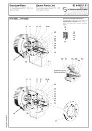
3.3 Dimensions of the Inverters . . . . . . . . . . . . . . . . . . . . . . . . . . 19<br />
3.3.1 Size 0 to Size 2: MDS 5007 to MDS 5150 . . . . . . . . 19<br />
3.3.2 Size 3: MDS 5220 to MDS 5450 . . . . . . . . . . . . . . . 20<br />
3.4 Brake resistors MDS 5xxx. . . . . . . . . . . . . . . . . . . . . . . . . . . . 21<br />
3.4.1 FZMU, FZZM . . . . . . . . . . . . . . . . . . . . . . . . . . . . . . 21<br />
3.4.2 VHPR . . . . . . . . . . . . . . . . . . . . . . . . . . . . . . . . . . . . 22<br />
3.4.3 FZZT, FZDT and FGFT . . . . . . . . . . . . . . . . . . . . . . 23<br />
3.4.4 Bottom Brake Resistor RB 5000 . . . . . . . . . . . . . . . 25<br />
3.5 Brake resistors MDS 5xxxA . . . . . . . . . . . . . . . . . . . . . . . . . . 26<br />
3.5.1 FZMU, FZZMU . . . . . . . . . . . . . . . . . . . . . . . . . . . . . 26<br />
3.5.2 GVADU, GBADU . . . . . . . . . . . . . . . . . . . . . . . . . . . 27<br />
3.5.3 FGFKU . . . . . . . . . . . . . . . . . . . . . . . . . . . . . . . . . . . 28<br />
3.5.4 Bottom Brake Resistor RB 5000 . . . . . . . . . . . . . . . 29<br />
3.6 Output Derater . . . . . . . . . . . . . . . . . . . . . . . . . . . . . . . . . . . . 30<br />
4 Installation . . . . . . . . . . . . . . . . . . . . . . . . . . . . . . 33<br />
4.1 Installation of the Inverter in the Switching Cabinet . . . . . . . . 33<br />
4.2 Accessories . . . . . . . . . . . . . . . . . . . . . . . . . . . . . . . . . . . . . . 35<br />
4.2.1 Installation of Bottom Brake Resistor . . . . . . . . . . . . 35<br />
4.2.2 Installation of EMC Shield Plate or Brake Module on<br />
the Inverter 37<br />
4.2.3 Installation of the Terminal Accessories . . . . . . . . . . 40<br />
4.2.4 Installation of CANopen®, PROFIBUS, EtherCAT®<br />
or PROFINET Accessories<br />
5 <strong><strong>Co</strong>nnection</strong> . . . . . . . . . . . . . . . . . . . . . . . . . . . . . 48<br />
5.1 Overview of the Terminals. . . . . . . . . . . . . . . . . . . . . . . . . . . . 48<br />
5.2 EMC <strong><strong>Co</strong>nnection</strong>. . . . . . . . . . . . . . . . . . . . . . . . . . . . . . . . . . . 50<br />
5.3 X10: 230 V/400 V Power. . . . . . . . . . . . . . . . . . . . . . . . . . . . . 51<br />
5.3.1 Power fuse . . . . . . . . . . . . . . . . . . . . . . . . . . . . . . . . 52<br />
5.3.2 RCD (Residual Current Protective Devices) . . . . . . 53<br />
5.3.3 Housing ground . . . . . . . . . . . . . . . . . . . . . . . . . . . . 53<br />
5.3.4 Forming . . . . . . . . . . . . . . . . . . . . . . . . . . . . . . . . . . 54<br />
43<br />
WE KEEP THINGS MOVING<br />
ID 442273.00 3
Table of contents<br />
Projecting manual POSIDRIVE® MDS 5000<br />
5.4 X11: 24 V Power . . . . . . . . . . . . . . . . . . . . . . . . . . . . . . . . . . . 55<br />
5.5 X1: Enable and Relay 1 . . . . . . . . . . . . . . . . . . . . . . . . . . . . . 57<br />
5.6 X20: Motor . . . . . . . . . . . . . . . . . . . . . . . . . . . . . . . . . . . . . . . 58<br />
5.7 X12: ASP 5001 – Safe Torque Off . . . . . . . . . . . . . . . . . . . . . 60<br />
5.8 X2; X300 – X302; X141: Motor Temperature Sensor, Motor<br />
Halting Brake 61<br />
5.9 X21: Braking Resistor . . . . . . . . . . . . . . . . . . . . . . . . . . . . . . . 65<br />
5.10 X22: DC Link <strong>Co</strong>upling . . . . . . . . . . . . . . . . . . . . . . . . . . . . . . 66<br />
5.11 X100-X103: Analog and Binary Signals . . . . . . . . . . . . . . . . . 70<br />
5.12 Encoder. . . . . . . . . . . . . . . . . . . . . . . . . . . . . . . . . . . . . . . . . . 76<br />
5.12.1 X4. . . . . . . . . . . . . . . . . . . . . . . . . . . . . . . . . . . . . . . 76<br />
5.12.2 X120. . . . . . . . . . . . . . . . . . . . . . . . . . . . . . . . . . . . . 80<br />
5.12.3 X140. . . . . . . . . . . . . . . . . . . . . . . . . . . . . . . . . . . . . 83<br />
5.12.4 Binary Input (BE) Encoder . . . . . . . . . . . . . . . . . . . . 86<br />
5.13 Fieldbus . . . . . . . . . . . . . . . . . . . . . . . . . . . . . . . . . . . . . . . . . 88<br />
5.13.1 X200: CANopen®. . . . . . . . . . . . . . . . . . . . . . . . . . . 88<br />
5.13.2 X200: PROFIBUS . . . . . . . . . . . . . . . . . . . . . . . . . . 89<br />
5.13.3 X200, X201: EtherCAT® . . . . . . . . . . . . . . . . . . . . . 90<br />
WE KEEP THINGS MOVING<br />
5.13.4 X200, X201: PROFINET® . . . . . . . . . . . . . . . . . . . . 91<br />
5.14 X3: PC, USS . . . . . . . . . . . . . . . . . . . . . . . . . . . . . . . . . . . . . . 92<br />
5.15 Cables. . . . . . . . . . . . . . . . . . . . . . . . . . . . . . . . . . . . . . . . . . . 93<br />
5.15.1 Motor Cables . . . . . . . . . . . . . . . . . . . . . . . . . . . . . . 93<br />
5.15.2 Encoder Cables . . . . . . . . . . . . . . . . . . . . . . . . . . . . 94<br />
6 Examples of connections. . . . . . . . . . . . . . . . . . 96<br />
7 Accessories . . . . . . . . . . . . . . . . . . . . . . . . . . . . 98<br />
4<br />
ID 442273.00
Introduction<br />
Projecting manual POSIDRIVE® MDS 5000<br />
1<br />
1 Introduction<br />
1.1 Purpose of the manual<br />
This document will give you technical data and information about the installation and connection of the inverter<br />
and its accessories. This technical documentation will enable the following personnel to perform their tasks<br />
correctly.<br />
• Project engineer - planning<br />
• Electrical specialist - installation and connection<br />
1.2 Other manuals<br />
The documentation of the MDS 5000 includes the following manuals:<br />
Manual <strong>Co</strong>ntents ID Latest version<br />
<strong>Co</strong>mmissioning Instructions<br />
Reinstallation, replacement, function<br />
test<br />
442296 V 5.6<br />
Projecting manual Installation and connection 442272 V 5.6<br />
Operating manual Set up the inverter 442284 V 5.6<br />
1.3 Further support<br />
If you have questions about the technology which have not been answered in this document, please contact:<br />
• Telephone: +49 (0) 7231 582-1187<br />
• E-Mail: applications@stoeber.de<br />
If you have questions about the documentation or training programs, please contact:<br />
• E-Mail: electronics@stoeber.de<br />
WE KEEP THINGS MOVING<br />
ID 442273.00<br />
5
2<br />
Notes on Safety<br />
Projecting manual POSIDRIVE® MDS 5000<br />
2 Notes on Safety<br />
The devices may cause risks. For these reasons, comply with the following:<br />
• The safety notes listed in the following sections and points<br />
• The technical rules and regulations.<br />
In addition, always read the appropriate documentation. STÖBER <strong>ANTRIEBSTECHNIK</strong> <strong>GmbH</strong> + <strong>Co</strong>. <strong>KG</strong> accepts<br />
no liability for damages caused by non-adherence to the instructions or applicable regulations. Subject<br />
to technical changes to improve the devices without prior notice. This documentation is purely a product description.<br />
It does not represent promised properties in the sense of warranty law.<br />
2.1 <strong>Co</strong>mponent part of the product<br />
The technical documentation is a component part of a product.<br />
• Since the technical documentation contains important information, always keep it handy in the vicinity of<br />
the device until the machine is disposed of.<br />
• If the product is sold, disposed of, or rented out, always include the technical documentation with the product.<br />
2.2 Operation in accordance with its intended use<br />
WE KEEP THINGS MOVING<br />
In the sense of DIN EN 50178 (previously VDE 0160), the inverters represent the electrical equipment of power<br />
electronics for the control of power flow in high-voltage current systems. They are designed exclusively to<br />
power:<br />
• Servo motors<br />
• Asynchronous motores<br />
Operation for purposes other than the intended use include the connection of other electrical loads!<br />
2.3 Risk assessment<br />
Before the manufacturer is allowed to put a machine on the market, he must have a danger analysis prepared<br />
as per machine guideline 06/42/EG. This analysis establishes the dangers connected with the use of the machine.<br />
The danger analysis is a multi-stage, iterative process. Since this documentation cannot begin to provide<br />
sufficient insight into the machine guidelines, please carefully study the latest standards and legal<br />
situation yourself. After the drive controller has been installed in machines, it cannot be commissioned until it<br />
has been determined that the machine complies with the regulations of EG guideline 06/42/EG.<br />
6<br />
ID 442273.00
Notes on Safety<br />
Projecting manual POSIDRIVE® MDS 5000<br />
2<br />
2.4 Ambient conditions<br />
Inverters are products of the restricted sales class as described in IEC 61800-3. This product may cause highfrequency<br />
interference in residential zones and the user may be asked to take suitable measures.<br />
The inverters are not designed for use in public low-voltage networks which power residential areas. Highfrequency<br />
interference must be expected when the inverters are used in such a network. The inverters are<br />
only intended for use in TN networks. The inverters are only designed for use on supply current networks<br />
which can delivery at the most a maximum of symmetrical rated short circuit current at 480 Volts as per the<br />
following table:<br />
Size<br />
BG 0 and BG 1<br />
BG 2<br />
BG 3<br />
Max. symmetrical rated short circuit current<br />
5000 A<br />
5000 A<br />
10000 A<br />
Install the inverter in a switching cabinet in which the permissible ambient temperature is not exceeded (see<br />
mounting instructions)..<br />
The following applications are prohibited:<br />
• Use in potentially explosive areas<br />
• Use in environments with harmful substances as per EN 60721 (e.g., oils, acids, gases, fumes, powders,<br />
irradiation)<br />
• Use with mechanical vibration and impact stresses which exceed the information in the technical data of<br />
the projecting manuals.<br />
Implementation of the following applications is only permitted when STÖBER <strong>ANTRIEBSTECHNIK</strong> <strong>GmbH</strong> +<br />
<strong>Co</strong>. <strong>KG</strong> has been contacted first for permission:<br />
• Use in non-stationary applications<br />
WE KEEP THINGS MOVING<br />
ID 442273.00<br />
7
2<br />
Notes on Safety<br />
Projecting manual POSIDRIVE® MDS 5000<br />
2.5 Qualified personnel<br />
Since the devices may harbor residual risks, all configuration, transportation, installation and commissioning<br />
tasks including operation and disposal may only be performed by trained personnel who are aware of the possible<br />
risks.<br />
Personnel must have the qualifications required for the job. The following table lists examples of occupational<br />
qualifications for the jobs:<br />
Activity<br />
Transportation and storage<br />
<strong>Co</strong>nfiguration<br />
Installation and connection<br />
<strong>Co</strong>mmissioning<br />
(of a standard application)<br />
Programming<br />
Operation<br />
Possible occupational qualifications<br />
Worker skilled in storage logistics or comparable<br />
training<br />
- Graduate engineer (electro-technology or electrical<br />
power technology)<br />
- Technician (m/f) (electro-technology)<br />
Electronics technician (m/f)<br />
- Technician (m/f) (electro-technology)<br />
- Master electro technician (m/f)<br />
Graduate engineer (electro-technology or electrical<br />
power technology)<br />
- Technician (m/f) (electro-technology)<br />
- Master electro technician (m/f)<br />
Disposal<br />
Electronics technician (m/f)<br />
Tab. 2-1: examples of occupational qualifications<br />
WE KEEP THINGS MOVING<br />
In addition, the valid regulations, the legal requirements, the reference books, this technical documentation<br />
and, in particular, the safety information contained therein must be carefully<br />
• read<br />
• understood and<br />
• complied with<br />
2.6 Transportation and storage<br />
Immediately upon receipt, examine the delivery for any transportation damages. Immediately inform the transportation<br />
company of any damages. If damages are found, do not commission the product. If the device is not<br />
to be installed immediately, store it in a dry, dust-free room. Please see the documentation for how to commission<br />
an inverter after it has been in storage for a year or longer.<br />
8<br />
ID 442273.00
Notes on Safety<br />
Projecting manual POSIDRIVE® MDS 5000<br />
2<br />
2.7 Installation and connection<br />
Installation and connection work are only permitted after the device has been isolated from the power!<br />
The accessory installation instructions allow the following actions during the installation of accessories:<br />
• The housing in the upper slot can be opened<br />
• The housing in the bottom slot can be opened.<br />
Opening the housing in another place or for other purposes is not permitted.<br />
Use only copper lines. For the line cross sections to be used, refer to DIN VDE 0298-4 or DIN EN 60204-1<br />
Appendix D and Appendix G.<br />
Protect the device from falling parts (pieces of wire, leads, metal parts, and so on) during installation or other<br />
tasks in the switching cabinet. Parts with conductive properties inside the inverter can cause short circuits or<br />
device failure.<br />
The motor must have an integrated temperature monitor with basic isolation in acc. with EN 61800-5-1 or external<br />
motor overload protection must be used.<br />
The permissible protection class is protective ground. Operation is not permitted unless the protective conductor<br />
is connected in accordance with the regulations.<br />
<strong>Co</strong>mply with the applicable instructions for installation and commissioning of motor and brakes.<br />
2.8 <strong>Co</strong>mmissioning, operation and service<br />
Remove additional coverings before commissioning so that the device cannot overheat. During installation,<br />
provide the free spaces specified in the projecting manuals to prevent the inverter from overheating.<br />
The housing of the drive controller must be closed before you turn on the supply voltage. When the supply<br />
voltage is on, dangerous voltages can be present on the connection terminals and the cables and motor terminals<br />
connected to them. Remember that the device is not necessarily de-energized after all indicators have<br />
gone off.<br />
When network voltage is applied, the following are prohibited:<br />
• Opening the housing<br />
• <strong>Co</strong>nnecting or disconnecting the connection terminals<br />
• Installing accessories<br />
Before carrying out any work on the machine, observe all the following five safety regulations in the abovementioned<br />
sequence:<br />
1. Enable. Ensure that you also activate the auxiliary circuits.<br />
2. Secure against switching on.<br />
3. Ensure that the parts are de-energized.<br />
4. Earth and short-circuit.<br />
5. <strong>Co</strong>ver or isolate any live neighboring parts.<br />
Information<br />
Please note that the discharge time for the intermediate circuit capacitors<br />
is 5 min. You can only ensure that the parts are de-energized after<br />
this time.<br />
WE KEEP THINGS MOVING<br />
ID 442273.00<br />
9
2<br />
Notes on Safety<br />
Projecting manual POSIDRIVE® MDS 5000<br />
You can then start your work on the drive controller. Repairs may only be performed by STÖBER ANTRIEB-<br />
STECHNIK <strong>GmbH</strong> + <strong>Co</strong>. <strong>KG</strong>.<br />
Send defective devices together with a fault description to:<br />
STÖBER <strong>ANTRIEBSTECHNIK</strong> <strong>GmbH</strong> + <strong>Co</strong>. <strong>KG</strong><br />
Department VS-EL<br />
Kieselbronner Str.12<br />
75177 Pforzheim<br />
GERMANY<br />
2.9 Disposal<br />
Please comply with the latest national and regional regulations! Dispose of the individual parts separately depending<br />
on their nature and currently valid regulations such as, for example:<br />
• Electronic scrap (PCBs)<br />
• Plastic<br />
• Sheet metal<br />
• <strong>Co</strong>pper<br />
• Aluminum<br />
2.10 Residual dangers<br />
WE KEEP THINGS MOVING<br />
The connected motor can be damaged with certain settings of inverters:<br />
• Longer operation against an applied motor halting brake<br />
• Longer operation of self-cooled motors at slow speeds<br />
Drives can reach dangerous excess speeds (e.g., setting of high output frequencies for motors and motor settings<br />
which are unsuitable for this). Secure the drive accordingly.<br />
10<br />
ID 442273.00
Notes on Safety<br />
Projecting manual POSIDRIVE® MDS 5000<br />
2<br />
2.11 Presentation of notes on safety<br />
NOTICE<br />
Notice<br />
means that property damage may occur<br />
if the stated precautionary measures are not taken.<br />
CAUTION!<br />
Caution<br />
with warning triangle means that minor injury may occur<br />
if the stated precautionary measures are not taken.<br />
WARNING!<br />
Warning<br />
means that there may be a serious danger of death<br />
if the stated precautionary measures are not taken.<br />
DANGER!<br />
Danger<br />
means that serious danger of death exists<br />
if the stated precautionary measures are not taken.<br />
Information<br />
indicates important information about the product or a highlighted portion<br />
of the documentation which requires special attention.<br />
WE KEEP THINGS MOVING<br />
ID 442273.00<br />
11
3<br />
Technical data<br />
Projecting manual POSIDRIVE® MDS 5000<br />
3 Technical data<br />
Product key<br />
MDS 5075<br />
Designation Power: 075 = 0.75 kW<br />
th<br />
5 generation<br />
3.1 General Data of the Inverters<br />
3.1.1 Transportation, Storage and Operating Environment<br />
Maximum surrounding air<br />
temperature during operation<br />
Temperature during<br />
storage/transportation<br />
Humidity<br />
Installation altitude<br />
0 °C to 45 °C for rated data<br />
Up to 55 °C with power reduction, 2.5 %/K<br />
20 °C to +70 °C<br />
Maximum change: 20 K/h<br />
Relative humidity: 85 %, no condensation<br />
Up to 1000 m above sea level without restrictions<br />
1000 to 2000 m above sea level with power reduction, 1.5 %/100 m<br />
Pollution degree 2 as per EN 50178<br />
Ventilation<br />
Built-in fan<br />
WE KEEP THINGS MOVING<br />
Vibration (operation)<br />
Vibration (transportation)<br />
3.1.2 Device Features<br />
Protection rating IP 20<br />
Interference suppression<br />
5 Hz ≤ f ≤ 9 Hz: 0.35 mm<br />
9 Hz ≤ f ≤ 200 Hz: 1 m/s<br />
5 Hz ≤ f ≤ 9 Hz: 3.5 mm<br />
9 Hz ≤ f ≤ 200 Hz: 10 m/s<br />
200 Hz ≤ f ≤ 500 Hz: 15 m/s<br />
EN 61800-3, interference emission, class C3<br />
High-voltage category III as per EN 61800-5-1<br />
12<br />
ID 442273.00
Technical data<br />
Projecting manual POSIDRIVE® MDS 5000<br />
3<br />
3.1.3 Weight<br />
Device<br />
Weight<br />
Without Packaging [kg]<br />
With Packaging [kg]<br />
MDS 5007<br />
MDS 5008<br />
2.2 3.2<br />
MDS 5015<br />
MDS 5040<br />
MDS 5075<br />
MDS 5110<br />
MDS 5150<br />
3.8 5.1<br />
5.0 6.1<br />
MDS 5220 11.8 13.6<br />
MDS 5370<br />
MDS 5450<br />
13.2 15.0<br />
If you order an inverter with accessory parts, the weight increases by the following amounts:<br />
• Accessory parts for higher option (fieldbus): 0.1 kg<br />
• Accessory parts for lower option (terminals): 0.2 kg<br />
WE KEEP THINGS MOVING<br />
ID 442273.00<br />
13
3<br />
Technical data<br />
Projecting manual POSIDRIVE® MDS 5000<br />
3.2 Electrical Data of the Inverters<br />
3.2.1 Size 0 (BG 0): MDS 5007 to MDS 5015<br />
Device MDS 5007 MDS 5008 MDS 5015<br />
Id. no.<br />
up to HW 190 (MDS 5xxx)<br />
start. from HW 200 (MDS 5xxxA)<br />
44556<br />
55401<br />
44557<br />
55402<br />
44558<br />
55403<br />
Recommended motor power 0.75 kW 0.75 kW 1.5 kW<br />
Input voltage<br />
(L1–N) 1 × 230 V<br />
+20 %/–40 %, 50/60 Hz<br />
(L1–L3) 3 × 400 V, +32 %/–50 %, 50 Hz<br />
(L1–L3) 3 × 480 V, +10 %/–58 %, 60 Hz<br />
Input rated current<br />
Id. 44556: 1 × 6 A<br />
Id. 55401: 1 × 6 A<br />
Id. 44557: 3 × 2 A<br />
Id. 55402: 3 × 2.2 A<br />
Output frequency<br />
Id. 44556, 44557, 44558: 0 to 400 Hz<br />
Id. 55401, 55402, 55403: 0 to 700 Hz<br />
Output voltage 0 to 230 V 0 to 400 V<br />
Id. 44558: 3 × 3.7<br />
Id. 55403: 3 × 4 A<br />
Operation with servo motor (control type servo)<br />
Rated current I N<br />
Id. 44556: 3 × 3 A<br />
Id. 55401: 3 × 3 A<br />
Id. 44557: 3 × 1.5 A<br />
Id. 55402: 3 × 1.7 A<br />
Id. 44558: 3 × 3 A<br />
Id. 55403: 3 × 3.4 A<br />
I max<br />
250 % for 2 s; 200 % for 5 s<br />
Switching frequency 8 kHz (adjustable up to 16 kHz with derating, see chap. 3.2.5)<br />
Operation with asynchronous motor (control types U/f, SLVC, VC)<br />
WE KEEP THINGS MOVING<br />
Rated current I N<br />
Id. 44556: 3 × 4 A<br />
Id. 55401: 3 × 4 A<br />
Id. 44557: 3 × 2.1 A<br />
Id. 55402: 3 × 2.3 A<br />
Id. 44558: 3 × 4 A<br />
Id. 55403: 3 × 4.5 A<br />
I max<br />
180 % for 5 s; 150 % for 30 s<br />
Switching frequency 4 kHz (adjustable up to 16 kHz with derating, see chap. 3.2.5)<br />
Power loss at I A = I N 80 W 65 W 90 W<br />
Power loss at I A = 0 A a)<br />
max. 30 W<br />
High-Voltage limit value 440 V 830 V<br />
Switch-on threshold<br />
Brake chopper<br />
400 V to 420 V 780 V to 800 V<br />
Switch-off threshold<br />
Brake chopper<br />
360 V to 380 V 740 V to 760 V<br />
Ext. braking resistor R Br min Id. 44556: 100 Ω<br />
Id. 55401: 100 Ω<br />
Id. 44557 or 44558: 200 Ω<br />
Id. 55402 or 55403: 100 Ω<br />
Ext. braking resistor P Br max 1.6 kW 3.2 kW<br />
a) Depends on the connected option boards and sensors (e.g., encoder)<br />
14<br />
ID 442273.00
Technical data<br />
Projecting manual POSIDRIVE® MDS 5000<br />
3<br />
3.2.2 Size 1 (BG 1): MDS 5040 to MDS 5075<br />
Device MDS 5040 MDS 5075<br />
Id. no.<br />
up to HW 190 (MDS 5xxx)<br />
start. from HW 200 (MDS 5xxxA)<br />
44560<br />
55404<br />
44561<br />
55405<br />
Recommended motor power 4.0 kW 7.5 kW<br />
Input voltage<br />
(L1–L3) 3 × 400 V, +32 %/–50 %, 50 Hz<br />
(L1–L3) 3 × 480 V, +10 %/–58 %, 60 Hz<br />
Input rated current 3 × 9.3 A 3 × 15.8 A<br />
Output frequency<br />
Output voltage<br />
Id. 44560, 44561: 0 to 400 Hz<br />
Id. 55404, 55405: 0 to 700 Hz<br />
0 to 400 V<br />
Operation with servo motor (control type servo)<br />
Rated current I N 3 × 6 A 3 × 10 A<br />
I max<br />
250 % for 2 s; 200 % for 5 s<br />
Switching frequency 8 kHz (adjustable up to 16 kHz with derating, see chap. 3.2.5)<br />
Operation with asynchronous motor (control types U/f, SLVC, VC)<br />
Rated current I N 3 × 10 A 3 × 16 A<br />
I max<br />
180 % for 5 s; 150 % for 30 s<br />
Switching frequency 4 kHz (adjustable up to 16 kHz with derating, see chap. 3.2.5)<br />
Power loss at I A = I N 170 W 200 W<br />
Power loss at I A = 0 A a)<br />
max. 30 W<br />
High-Voltage limit value<br />
Switch-on threshold<br />
Brake chopper<br />
Switch-off threshold<br />
Brake chopper<br />
830 V<br />
780 V to 800 V<br />
740 V to 760 V<br />
Ext. braking resistor R Br min 100 Ω 47 Ω<br />
Ext. braking resistor P Br max 6.4 kW 13.6 kW<br />
a) Depends on the connected option boards and sensors (e.g., encoder).<br />
WE KEEP THINGS MOVING<br />
ID 442273.00<br />
15
3<br />
Technical data<br />
Projecting manual POSIDRIVE® MDS 5000<br />
3.2.3 Size 2 (BG 2): MDS 5110 and MDS 5150<br />
Device MDS 5110 MDS 5150<br />
Id. no.<br />
up to HW 190 (MDS 5xxx)<br />
start. from HW 200 (MDS 5xxxA)<br />
44562<br />
55406<br />
44563<br />
55407<br />
Recommended motor power 11 kW 15 kW<br />
Input voltage<br />
(L1–L3) 3 × 400 V, +32 %/–50 %, 50 Hz<br />
(L1–L3) 3 × 480 V, +10 %/–58 %, 60 Hz<br />
Input rated current 3 × 24.5 A 3 × 32.6 A<br />
Output frequency<br />
Output voltage<br />
Id. 44562, 44563: 0 to 400 Hz<br />
Id. 55406, 55407: 0 to 700 Hz<br />
0 to 400 V<br />
Operation with servo motor (control type servo)<br />
Rated current I N 3 × 14 A 3 × 20 A<br />
I max<br />
250 % for 2 s; 200 % for 5 s<br />
Switching frequency 8 kHz (adjustable up to 16 kHz with derating, see chap. 3.2.5)<br />
Operation with asynchronous motor (control types U/f, SLVC, VC)<br />
Rated current I N 3 × 22 A 3 × 32 A<br />
WE KEEP THINGS MOVING<br />
I max<br />
180 % for 5 s; 150 % for 30 s<br />
Switching frequency 4 kHz (adjustable up to 16 kHz with derating, see chap. 3.2.5)<br />
Power loss at I A = I N 220 W 280 W<br />
Power loss at I A = 0 A a)<br />
max. 30 W<br />
High-Voltage limit value<br />
Switch-on threshold<br />
Brake chopper<br />
Switch-off threshold<br />
Brake chopper<br />
830 V<br />
780 V to 800 V<br />
740 V to 760 V<br />
Ext. braking resistor R Br min<br />
22 Ω<br />
Ext. braking resistor P Br max<br />
29.1 kW<br />
a) Depends on the connected option boards and sensors (e.g., encoder).<br />
16<br />
ID 442273.00
Technical data<br />
Projecting manual POSIDRIVE® MDS 5000<br />
3<br />
3.2.4 Size 3 (BG 3): MDS 5220 to MDS 5450<br />
Device MDS 5220 MDS 5370 MDS 5450<br />
Id. no.<br />
up to HW 190 (MDS 5xxx)<br />
start. from HW 200 (MDS 5xxxA)<br />
44564<br />
55408<br />
44566<br />
55409<br />
44567<br />
55410<br />
Recommended motor power 22 kW 37 kW 45 kW<br />
Input voltage<br />
(L1–L3) 3 × 400 V, +32 %/–50 %, 50 Hz<br />
(L1–L3) 3 × 480 V, +10 %/–58 %, 60 Hz<br />
Input rated current 3 × 37 A 3 × 62 A 3 × 76 A<br />
Output frequency<br />
Id. 44564, 44566, 44567: 0 to 400 Hz<br />
Id. 55408, 55409, 55410: 0 to 700 Hz<br />
Output voltage<br />
0 to 400 V<br />
Operation with servo motor (control type servo)<br />
Rated current I N 3 × 30 A 3 × 50 A 3 × 60 A<br />
I max<br />
250 % for 2 s; 200 % for 5 s<br />
Switching frequency 8 kHz (adjustable up to 16 kHz with derating, see chap. 3.2.5)<br />
Operation with asynchronous motor (control types U/f, SLVC, VC)<br />
Rated current I N 3 × 44 A 3 × 70 A 3 × 85 A<br />
I max<br />
180 % for 5 s; 150 % for 30 s<br />
Switching frequency 4 kHz (adjustable up to 16 kHz with derating, see chap. 3.2.5)<br />
Power loss at I A = I N approx. 350 W approx. 600 W approx. 1000 W<br />
Power loss at I A = 0 A a)<br />
max. 55 W<br />
High-Voltage limit value<br />
Switch-on threshold<br />
Brake chopper<br />
Switch-off threshold<br />
Brake chopper<br />
Internal braking resistor<br />
Ext. braking resistor R Br min<br />
Ext. braking resistor P Br max<br />
a) Depends on the connected option boards and sensors (e.g., encoder).<br />
830 V<br />
780 V to 800 V<br />
740 V to 760 V<br />
30 Ω: 100 W/max. 21 kW<br />
15 Ω<br />
42 kW<br />
WE KEEP THINGS MOVING<br />
ID 442273.00<br />
17
3<br />
Technical data<br />
Projecting manual POSIDRIVE® MDS 5000<br />
3.2.5 Derating by Increasing the Switching Frequency<br />
Based on the switching frequency, the following values of the output currents result. Remember that only 8<br />
kHz and 16 kHz can be set for control type servo.<br />
Inverter Switching frequency (Parameter B24)<br />
4 kHz 8 kHz 16 kHz<br />
MDS 5007 4.0 A 3.0 A 2.0 A<br />
MDS 5008<br />
– Id. 44557:<br />
– Id. 55402:<br />
2.1 A<br />
2.3 A<br />
1.5 A<br />
1.7 A<br />
1.1 A<br />
1.2 A<br />
MDS 5015<br />
– Id. 44558:<br />
– Id. 55403:<br />
4.0 A<br />
4.5 A<br />
3.0 A<br />
3.4 A<br />
2.0 A<br />
2.2 A<br />
MDS 5040 10.0 A 6.0 A 3.3 A<br />
MDS 5075 16.0 A 10.0 A 5.7 A<br />
MDS 5110 22.0 A 14.0 A 8.1 A<br />
MDS 5150 32.0 A 20.0 A 11.4 A<br />
MDS 5220 44.0 A 30.0 A 18.3 A<br />
MDS 5370 70.0 A 50.0 A 31.8 A<br />
MDS 5450 85.0 A 60.0 A 37.8 A<br />
WE KEEP THINGS MOVING<br />
3.2.6 UL<br />
Additional information for use under UL conditions (UL – Underwriters Laboratories).<br />
• Internal overload protection operates at maximum 200 % of the motor full load current after 3 seconds or<br />
as otherwise specified in the technical data.<br />
• In case these devices are to be used with an externally mounted braking resistore, over-temperature protection<br />
shall be provided separately.<br />
• Main equipment grounding markings:The main ground connections are marked "PE" or with the international<br />
ground symbol (IEC 417, Symbol 5019 ).<br />
• Integral solid state short circuit protection does not provide branch circuit protection. Branch circuit protection<br />
must be provided in accordance with the Manufacturer Instructions, National Electrical <strong>Co</strong>de and<br />
any additional local codes", or the equivalent.<br />
18<br />
ID 442273.00
Technical data<br />
Projecting manual POSIDRIVE® MDS 5000<br />
3<br />
3.3 Dimensions of the Inverters<br />
3.3.1 Size 0 to Size 2: MDS 5007 to MDS 5150<br />
w<br />
b<br />
d 2<br />
d 1<br />
ESC<br />
I/O<br />
a<br />
h 3<br />
h 2<br />
h 1<br />
e<br />
Absolute<br />
Encoder<br />
Support<br />
AES<br />
f<br />
EM 5000 / BRM 5000<br />
Dimensions [mm] Size 0 Size 1 Size 2<br />
Inverter Height h 1 300<br />
h a)<br />
2 360<br />
b)<br />
h 3 365<br />
Width w 70 105<br />
Depth d 1 175 260 260<br />
c)<br />
d 2 193 278 278<br />
EMC shield plate Height e 37.5<br />
Depth f 40<br />
Mounting holes Vertical distance a 283<br />
Vertical distance to upper edge b 6<br />
a) h 2 = Height incl. EMC shield plate EM 5000 or brake module BRM 5000<br />
b) h 3 = Height incl. AES<br />
c) d 2 = Depth incl. brake resistor RB 5000<br />
WE KEEP THINGS MOVING<br />
ID 442273.00<br />
19
3<br />
Technical data<br />
Projecting manual POSIDRIVE® MDS 5000<br />
3.3.2 Size 3: MDS 5220 to MDS 5450<br />
g<br />
w<br />
c<br />
g<br />
d 1<br />
a<br />
POSIDRIVE ®<br />
MDS 5000<br />
X3<br />
ESC<br />
I/O<br />
h 1<br />
BRM 5000<br />
Absolute<br />
Encoder<br />
Support<br />
AES<br />
b<br />
g<br />
c<br />
g<br />
Dimensions [mm] Size 3<br />
WE KEEP THINGS MOVING<br />
Inverter Height h 1 382.5<br />
Width w 190<br />
Depth d 1 276<br />
Mounting holes Vertical distance a 365<br />
Vertical distance to lower edge b 6<br />
Horizontal distance c 150<br />
Horizontal distance to side edge g 20<br />
20<br />
ID 442273.00
Technical data<br />
Projecting manual POSIDRIVE® MDS 5000<br />
3<br />
3.4 Brake resistors MDS 5xxx<br />
3.4.1 FZMU, FZZM<br />
Typ FZMU FZZM<br />
400x65<br />
600 W 100 Ω<br />
400x65<br />
600 W 30 Ω<br />
400x65<br />
1200 W 30 Ω<br />
400x65<br />
1200 W 20 Ω<br />
ID No 49010 49011 41642 41650<br />
MDS 5007 X — — —<br />
MDS 5008 — — — —<br />
MDS 5015 — — — —<br />
MDS 5040 X — — —<br />
MDS 5075 X — — —<br />
MDS 5110 — X X —<br />
MDS 5150 — X X —<br />
MDS 5220 — X — X<br />
MDS 5370 — X — X<br />
MDS 5450 — X — X<br />
Type<br />
L × D<br />
[mm]<br />
H<br />
[mm]<br />
K<br />
[mm]<br />
M<br />
[mm]<br />
O<br />
[mm]<br />
R<br />
[mm]<br />
U<br />
[mm]<br />
X<br />
[mm]<br />
Thermal time<br />
constant τ[s]<br />
Weight<br />
[kg]<br />
FZMU<br />
400x65 400 × 65 120 6.5 × 12 430 485 92 64 10 40.0 approx.<br />
2.2<br />
FZZM<br />
400x65 400 × 65 120 6.5 × 12 426 446 185 150 10 40.0 approx.<br />
4.2<br />
K<br />
L<br />
M<br />
O<br />
M<br />
U<br />
øD<br />
X<br />
FZMU<br />
R<br />
U<br />
Drill pattern<br />
H<br />
K<br />
FZZM(U)<br />
R<br />
K<br />
U<br />
Protect.<br />
Rating<br />
IP 20<br />
IP 20<br />
WE KEEP THINGS MOVING<br />
ID 442273.00<br />
21
3<br />
Technical data<br />
Projecting manual POSIDRIVE® MDS 5000<br />
3.4.2 VHPR<br />
Type<br />
VHPR<br />
VHPR150V<br />
150 W 300 Ω<br />
VHPR150V<br />
150 W 100 Ω<br />
VHPR500V<br />
400 W 47 Ω<br />
ID no. 45972 45973 45974<br />
MDS 5007 — X —<br />
MDS 5008 X — —<br />
MDS 5015 X — —<br />
MDS 5040 — X —<br />
MDS 5075 — X X<br />
MDS 5110 — — X<br />
MDS 5150 — — X<br />
MDS 5220 — — X<br />
MDS 5370 — — X<br />
MDS 5450 — — X<br />
Type L C B A D E F τ Weight Protection<br />
rating<br />
mm s g<br />
WE KEEP THINGS MOVING<br />
VHPR150V<br />
150 W 300 Ω<br />
VHPR150V<br />
150 W 100 Ω<br />
VHPR500V<br />
400 W 47 Ω<br />
212 193 ± 2 40 21 4,3 8 13 46,6 ca. 310 IP 54<br />
212 193 ± 2 40 21 4,3 8 13 8,1 ca. 310 IP 54<br />
337 317 ± 2 60 31 5,3 11,5 19,5 65,0 ca. 1020 IP 54<br />
22<br />
ID 442273.00
Technical data<br />
Projecting manual POSIDRIVE® MDS 5000<br />
3<br />
3.4.3 FZZT, FZDT and FGFT<br />
Type<br />
FZZT<br />
400 × 65<br />
1200 W<br />
20 Ω<br />
FZDT<br />
500 × 65<br />
2500 W<br />
20 Ω<br />
FGFT<br />
3111202<br />
6000 W<br />
20 Ω<br />
ID no. 41651 41653 41655<br />
MDS 5220 X X X<br />
MDS 5370 X X X<br />
MDS 5450 X X X<br />
Type<br />
FZZT<br />
400 × 65<br />
FZDT<br />
500 × 65<br />
L × D [mm] 400 × 65 500 × 65<br />
H [mm] 120 120<br />
K [mm] 6,5 × 12 6,5 × 12<br />
M [mm] 426 526<br />
O [mm] 506 606<br />
R [mm] 185 275<br />
U [mm] 150 240<br />
Thermal time const. τ [s] 30<br />
Weight [kg] ca. 4,6 ca. 7,8<br />
FZZT<br />
L<br />
R<br />
M<br />
10<br />
K<br />
O<br />
U<br />
K<br />
U<br />
M<br />
øD<br />
K<br />
FZDT<br />
R<br />
U<br />
WE KEEP THINGS MOVING<br />
ID 442273.00<br />
23
3<br />
Technical data<br />
Projecting manual POSIDRIVE® MDS 5000<br />
Type FGFT 3111202<br />
A [mm] 370<br />
B [mm] 395<br />
C [mm] 455<br />
Thermal time constant τ [s] 20<br />
Weight [kg] approx. 13<br />
Protection Rating IP 20<br />
490 C<br />
WE KEEP THINGS MOVING<br />
260<br />
380<br />
Ø10,5<br />
A<br />
B<br />
A<br />
10,5<br />
380<br />
24<br />
ID 442273.00
Technical data<br />
Projecting manual POSIDRIVE® MDS 5000<br />
3<br />
3.4.4 Bottom Brake Resistor RB 5000<br />
Type RB 5022<br />
100 W<br />
22 Ω<br />
RB 5047<br />
60 W<br />
47 Ω<br />
RB 5100<br />
60 W<br />
100 Ω<br />
RB 5200<br />
40 W<br />
200 Ω<br />
ID no. 45618 44966 44965 44964<br />
MDS 5007 — — X X<br />
MDS 5008 — — — X<br />
MDS 5015 — — — X<br />
MDS 5040 — — X —<br />
MDS 5075 — X — —<br />
MDS 5110 X — — —<br />
MDS 5150 X — — —<br />
See installation on inverter (chapter 4)!<br />
Type RB 5022<br />
100 W<br />
22 Ω<br />
RB 5047<br />
60 W<br />
47 Ω<br />
RB 5100<br />
60 W<br />
100 Ω<br />
RB 5200<br />
40 W<br />
200 Ω<br />
Height x width x depth [mm] 300 x 94 x 18 300 x 62 x 18<br />
Drilling template<br />
corresponds to size:<br />
Size 2 Size 1 Size 0 and 1 Size 0<br />
Thermal time constant τ [s] 8 6<br />
Weight [g] approx. 640 approx. 460 approx. 440<br />
Length of cable [mm] 250<br />
Maximum torque for studs<br />
[Nm]<br />
Protection Rating IP 40<br />
5<br />
WE KEEP THINGS MOVING<br />
ID 442273.00<br />
25
3<br />
Technical data<br />
Projecting manual POSIDRIVE® MDS 5000<br />
3.5 Brake resistors MDS 5xxxA<br />
3.5.1 FZMU, FZZMU<br />
Type FZMU FZZMU<br />
400x65<br />
600 W 100 Ω<br />
400x65<br />
600 W 22 Ω<br />
400x65<br />
600 W 15 Ω<br />
400x65<br />
1200 W 47 Ω<br />
400x65<br />
1200 W 22 Ω<br />
400x65<br />
1200 W 15 Ω<br />
ID No. 49010 55445 55446 53895 55447 55448<br />
MDS 5007A X — — — — —<br />
MDS 5008A X — — — — —<br />
MDS 5015A X — — — — —<br />
MDS 5040A — — — X — —<br />
MDS 5075A — — — X — —<br />
MDS 5110A — X — — X —<br />
MDS 5150A — X — — X —<br />
MDS 5220A — — X — — X<br />
MDS 5370A — — X — — X<br />
MDS 5450A — — X — — X<br />
WE KEEP THINGS MOVING<br />
Typ L × D H K M O R U X τ Pulse power<br />
for < 1 s<br />
Weight Protection<br />
rating<br />
mm s kW kg<br />
FZMU<br />
400x65<br />
400 × 65 120 6.5 × 12 430 485 92 64 10 40.0 18 ca. 2.2 IP 20<br />
FZZMU<br />
400x65<br />
400 × 65 120 6.5 × 12 426 450 185 150 10 40.0 36 ca. 4.2 IP 20<br />
K<br />
L<br />
M<br />
O<br />
M<br />
U<br />
øD<br />
X<br />
FZMU<br />
R<br />
U<br />
Drill pattern<br />
H<br />
K<br />
FZZM(U)<br />
R<br />
K<br />
U<br />
26<br />
ID 442273.00
Technical data<br />
Projecting manual POSIDRIVE® MDS 5000<br />
3<br />
3.5.2 GVADU, GBADU<br />
Type GVADU GBADU<br />
210 × 20<br />
150 W 100 Ω<br />
265 × 30<br />
300 W 100 Ω<br />
335 × 30<br />
400 W 47 Ω<br />
265 × 30<br />
300 W 22 Ω<br />
ID no. 55441 55442 55443 55444<br />
MDS 5007A X X — —<br />
MDS 5008A X X — —<br />
MDS 5015A X X — —<br />
MDS 5040A X X — —<br />
MDS 5075A — — X —<br />
MDS 5110A — — — X<br />
MDS 5150A — — — X<br />
MDS 5220A — — — X<br />
MDS 5370A — — — X<br />
MDS 5450A — — — X<br />
Type A H C D E F G J B τ Pulse power<br />
for < 1 s<br />
Weight<br />
Protection<br />
rating<br />
mm ° s kW g<br />
GVADU<br />
210 × 20<br />
GBADU<br />
265 × 30<br />
GBADU<br />
335 × 30<br />
210 192 20 40 18.2 6.2 2 4.3 65 60 3.3 300 IP 54<br />
265 246 30 60 28.8 10.8 3 5.3 73 60 6.6 950 IP 54<br />
335 316 30 60 28.8 10.8 3 5.3 73 60 8.8 1200 IP 54<br />
WE KEEP THINGS MOVING<br />
ID 442273.00<br />
27
3<br />
Technical data<br />
Projecting manual POSIDRIVE® MDS 5000<br />
3.5.3 FGFKU<br />
Type<br />
FGFKU<br />
3100502<br />
2500 W 22 Ω<br />
3100502<br />
2500 W 15 Ω<br />
3111202<br />
6000 W 15 Ω<br />
3121602<br />
8000 W 15 Ω<br />
ID no. 55449 55450 55451 53897<br />
MDS 5110A X — — —<br />
MDS 5150A X — — —<br />
MDS 5220A X — — —<br />
MDS 5370A — X X X<br />
MDS 5450A — X X X<br />
Type 3100502 3111202 3121602<br />
A [mm] 270 370 570<br />
B [mm] 295 395 595<br />
C [mm] 355 455 655<br />
Thermal time const. τ [s] 30 20 20<br />
Pulse power for < 1 s [kW] 50 120 160<br />
Weight [kg] ca. 7,5 12 18<br />
WE KEEP THINGS MOVING<br />
490 C<br />
Ø10,5<br />
A<br />
380<br />
B<br />
A<br />
Drill pattern<br />
260<br />
10,5<br />
380<br />
28<br />
ID 442273.00
Technical data<br />
Projecting manual POSIDRIVE® MDS 5000<br />
3<br />
3.5.4 Bottom Brake Resistor RB 5000<br />
Type RB 5022<br />
100 W<br />
22 Ω<br />
RB 5047<br />
60 W<br />
47 Ω<br />
RB 5100<br />
60 W<br />
100 Ω<br />
ID no. 45618 44966 44965<br />
MDS 5007A — — X<br />
MDS 5008A — — X<br />
MDS 5015A — — X<br />
MDS 5040A — X X<br />
MDS 5075A — X —<br />
MDS 5110A X — —<br />
MDS 5150A X — —<br />
See installation on inverter (chapter 4)!<br />
Type RB 5022<br />
100 W<br />
22 Ω<br />
RB 5047<br />
60 W<br />
47 Ω<br />
RB 5100<br />
60 W<br />
100 Ω<br />
Height x width x depth [mm] 300 x 94 x 18 300 x 62 x 18<br />
Drilling template<br />
corresponds to size:<br />
Thermal time constant τ [s] 8<br />
Size 2 Size 1 Size 0 and 1<br />
Weight [g] approx. 640 approx. 460 approx. 440<br />
Length of cable [mm] 250<br />
Maximum torque for studs<br />
[Nm]<br />
Protection Rating IP 40<br />
5<br />
WE KEEP THINGS MOVING<br />
ID 442273.00<br />
29
3<br />
Technical data<br />
Projecting manual POSIDRIVE® MDS 5000<br />
3.6 Output Derater<br />
WARNING!<br />
Danger of fire! Use of the output deraters outside the rated specifications (cable length, current, frequency,<br />
etc.) may cause the derater to overheat.<br />
Always operate the deraters at the most at the rated specifications.<br />
NOTICE<br />
Danger of machine standstill! The motor temperature sensor evaluation is malfunctioning due to cable<br />
capacities.<br />
<br />
If you use cables which are longer than 50 m and the cables are not from STÖBER <strong>ANTRIEBSTECHNIK</strong><br />
<strong>GmbH</strong> & <strong>Co</strong>. <strong>KG</strong>, the cores for the motor temperature sensor and the brake must be separate (maximum<br />
length: 100 m).<br />
Information<br />
The following technical data apply to the switching frequencies 4 and 8<br />
kHz. Different operating conditions are possible in consultation with<br />
STÖBER <strong>ANTRIEBSTECHNIK</strong> <strong>GmbH</strong> & <strong>Co</strong>. <strong>KG</strong>.<br />
WE KEEP THINGS MOVING<br />
30<br />
ID 442273.00
Technical data<br />
Projecting manual POSIDRIVE® MDS 5000<br />
3<br />
Type<br />
output derater<br />
4EP3720-0ES41<br />
output derater<br />
4EP3820-0CS41<br />
output derater<br />
4EP4020-0RS41<br />
ID no. 53188 53189 53190<br />
Voltage range<br />
Frequency range<br />
3 x 0 to 480 V<br />
0 to 200 Hz<br />
Operation with servo motor (control type servo control)<br />
Rated current 8 kHz [output derater] 3.3 A 15.2 A 30.4 A<br />
Suitable size [inverter] Size 0 Size 1 Size 2<br />
Max. overload 8 kHz [inverter]<br />
Max. motor voltage [inverter]<br />
Max. dU/dt [inverter]<br />
250 % for 2 s, 200 % for 5 s<br />
1.0 kV<br />
3.5 kV/µsec<br />
Operation with asynchronous motor (control types V/f, SLVC, VC)<br />
Rated current 4 kHz [output derater] 4 A 17.5 A 38 A<br />
Suitable size [inverter] Size 0 Size 1 Size 2<br />
Max. overload 4 kHz [inverter]<br />
Max. motor voltage [inverter]<br />
Max. dU/dt [inverter]<br />
180 % for 5 s, 150 % for 30 s<br />
1.4 kV<br />
3 kV/µsec<br />
Type 4EP3720-0ES41 4EP3820-0CS41 4EP4020-0RS41<br />
Max. permissible cable length with<br />
output derater<br />
100 m<br />
Max. surrounding air temperature 40 °C<br />
Design<br />
open<br />
Winding losses 11 W 29 W 61 W<br />
Iron losses 25 W 16 W 33 W<br />
<strong><strong>Co</strong>nnection</strong>s<br />
Screw-type terminals<br />
Max. line cross section 10 mm 2<br />
Approvals<br />
WE KEEP THINGS MOVING<br />
ID 442273.00<br />
31
3<br />
Technical data<br />
Projecting manual POSIDRIVE® MDS 5000<br />
Type 4EP3720-0ES41 4EP3820-0CS41 4EP4020-0RS41<br />
h [mm] max. 153 max. 153 max. 180<br />
w [mm] 178 178 219<br />
d [mm] 73 88 119<br />
a1 [mm] 166 166 201<br />
a2 [mm] 113 113 136<br />
b1 [mm] 53 68 89<br />
b2 [mm] 49 64 76<br />
e [mm] 5.8 5.8 7<br />
f [mm] 11 11 13<br />
Screwed glands – M M5 M5 M6<br />
Weight [kg] 2.9 5.9 8.8<br />
A<br />
M 1:2<br />
h<br />
w<br />
a1<br />
WE KEEP THINGS MOVING<br />
a2<br />
Mounting borings in<br />
acc. to DIN EN 60852-4<br />
b1<br />
A<br />
a1<br />
M<br />
b2<br />
b1<br />
d<br />
f<br />
e<br />
32<br />
ID 442273.00
Installation<br />
Projecting manual POSIDRIVE® MDS 5000<br />
4<br />
4 Installation<br />
This chapter will give you information about installation. This includes:<br />
• Installation of the inverter in the switching cabinet<br />
• Installation of accessories on or in the inverter<br />
WARNING!<br />
Danger of injury/death and property damage due to electric shock!<br />
Before installing accessories, turn off all voltage supplies! Then wait 5 minutes for the DC link capacitors<br />
to discharge. Never begin with accessory installation until after this!<br />
4.1 Installation of the Inverter in the Switching Cabinet<br />
NOTICE<br />
Danger of property damage from incorrect installation of the devices!<br />
It is essential to comply with the following installation instructions to avoid damage to the devices.<br />
• The inverters must be installed in the switching cabinet (protection rating IP 20 of the inverter)<br />
• The installation site must be free of dust, corrosive fumes and all kinds of liquids (as pollution degree 2 in<br />
accordance with EN 50178).<br />
• The installation site must be free of atmospheric moisture.<br />
• Avoid condensation (e.g., use anti-condensation heating elements).<br />
• Use mounting plates with conductive surfaces (e.g., unpainted) for EMC considerations.<br />
• Secure the inverters to the mounting plate with M5 screws.<br />
• The inverters must be installed vertically:<br />
WE KEEP THINGS MOVING<br />
ID 442273.00<br />
33
4<br />
Installation<br />
Projecting manual POSIDRIVE® MDS 5000<br />
• Avoid installation above heat-generating devices:<br />
• Provide the minimum free space required so that enough air can circulate.<br />
C<br />
C<br />
B<br />
A<br />
WE KEEP THINGS MOVING<br />
Min. free space[dimensions<br />
in mm]<br />
A<br />
Upwards<br />
B<br />
Downwards<br />
C<br />
Sidewards<br />
Size 0 – Size 2 100 100 5<br />
Size 0 – Size 2<br />
With EMC shield plateor<br />
Brake Module<br />
100 120 5<br />
Size 3 100 100 5<br />
34<br />
ID 442273.00
Installation<br />
Projecting manual POSIDRIVE® MDS 5000<br />
4<br />
4.2 Accessories<br />
4.2.1 Installation of Bottom Brake Resistor<br />
WARNING!<br />
Danger of injury/death and property damage due to electric shock!<br />
Before installing accessories, turn off all voltage supplies! Then wait 5 minutes for the DC link capacitors<br />
to discharge. Never begin with accessory installation until after this!<br />
Prerequisites:<br />
• You have bored the holes for threaded bolts (as per chapter 3.3 Dimensions of the Inverters) in the switching<br />
cabinet where the inverter is to be installed. The threaded bolts are included with the bottom brake<br />
resistor.<br />
You will need the following for installation:<br />
• The threaded bolts included with the bottom brake resistor<br />
• The screws and washers included with the bottom brake resistor<br />
• A Phillips screwdriver<br />
Installation of the bottom brake resistor<br />
1 Secure the bottom brake resistor to the mounting panel of the switching cabinet<br />
with the threaded bolts:<br />
WE KEEP THINGS MOVING<br />
ID 442273.00<br />
35
4<br />
Installation<br />
Projecting manual POSIDRIVE® MDS 5000<br />
2 Place the inverter on the guide rails:<br />
3 Press the inverter downwards on the guide rails:<br />
WE KEEP THINGS MOVING<br />
4 Secure the inverter to the threaded bolts with the screws and washers:<br />
<br />
You have now installed the bottom brake resistor.<br />
36<br />
ID 442273.00
Installation<br />
Projecting manual POSIDRIVE® MDS 5000<br />
4<br />
4.2.2 Installation of EMC Shield Plate or Brake Module on the Inverter<br />
WARNING!<br />
Danger of injury/death and property damage due to electric shock!<br />
Before installing accessories, turn off all voltage supplies! Then wait 5 minutes for the DC link capacitors<br />
to discharge. Never begin with accessory installation until after this!<br />
The inverter controls a 24 V brake with brake module BRM 5000. You can use the EM 5000 accessory if you<br />
want to connect EMC shielding with the inverter housing. Mechanically BRM 5000 and EM 5000 are the same<br />
accessory parts. Installation is also the same for both accessory parts. But please remember that installation<br />
of the accessory for size 0, 1 and 2 inverters is not the same as for size 3 inverters.<br />
Prerequisites:<br />
• You have already installed the inverter in the switching cabinet (sizes 0 to 2)<br />
You will need<br />
• A tool to unscrew the mounting screw (size 3: Phillips screw driver)<br />
Installation of EMC shield plate or brake module on the inverter (size 0, 1 or<br />
2)<br />
1 Remove the bottom mounting screw and washers from the inverter:<br />
2 Slide the component into the openings at a slight angle:<br />
WE KEEP THINGS MOVING<br />
ID 442273.00<br />
37
4<br />
Installation<br />
Projecting manual POSIDRIVE® MDS 5000<br />
3 Press the back of the component onto the wall of the switching cabinet:<br />
4 Secure the component to the switching cabinet and inverter with the mounting<br />
screw and the washers:<br />
<br />
You have now installed the accessory.<br />
WE KEEP THINGS MOVING<br />
38<br />
ID 442273.00
Installation<br />
Projecting manual POSIDRIVE® MDS 5000<br />
4<br />
Installation of EMC shield plate or brake module on the inverter (size 3)<br />
1 Remove the mounting screw and washers from the front of the inverter:<br />
2 Place the component on the device so that the guide rails are in the openings:<br />
3 Secure the component to the device with the mounting screw and the washers:<br />
<br />
You have now installed the accessory.<br />
WE KEEP THINGS MOVING<br />
ID 442273.00<br />
39
4<br />
Installation<br />
Projecting manual POSIDRIVE® MDS 5000<br />
4.2.3 Installation of the Terminal Accessories<br />
WARNING!<br />
Danger of injury/death and property damage due to electric shock!<br />
Before installing accessories, turn off all voltage supplies! Then wait 5 minutes for the DC link capacitors<br />
to discharge. Never begin with accessory installation until after this!<br />
CAUTION!<br />
Danger of property damage due to electrostatic discharge, among others!<br />
Provide suitable protective measures while handling open PCBs (e.g., ESD clothing, environment free of<br />
dirt and grease).<br />
Do not touch the gold contact surfaces.<br />
You will need one of the following accessory parts before you can connect binary and analog signals to the<br />
inverter. Installation is the same for all four accessory parts.<br />
• SEA 5001, ID no. 49576<br />
• REA 5001, ID no. 49854<br />
• XEA 5001, ID no. 49015<br />
You will need:<br />
• A Phillips screwdriver<br />
• The screws which are pre-mounted on the accessory.<br />
Installation of an SEA 5001, REA 5001 or XEA 5001 in an MDS 5000<br />
WE KEEP THINGS MOVING<br />
1 Unlock the snap catch on the inverter cover:<br />
40<br />
ID 442273.00
Installation<br />
Projecting manual POSIDRIVE® MDS 5000<br />
4<br />
2 Lift up the upper end of the cover from the inverter:<br />
3 Lift the cover up and remove it from the inverter:<br />
4 Insert the accessory part at a slant with the gold contacts in front. The gold<br />
contacts must be in front of the black terminal block.<br />
WE KEEP THINGS MOVING<br />
ID 442273.00<br />
41
4<br />
Installation<br />
Projecting manual POSIDRIVE® MDS 5000<br />
5 Slide the gold contacts into the black connector.<br />
6 Secure the accessory part to the inverter with the mounting screws:<br />
WE KEEP THINGS MOVING<br />
<br />
You have now installed the accessory.<br />
42<br />
ID 442273.00
Installation<br />
Projecting manual POSIDRIVE® MDS 5000<br />
4<br />
4.2.4 Installation of CANopen®, PROFIBUS, EtherCAT® or PROFINET Accessories<br />
WARNING!<br />
Danger of injury/death and property damage due to electric shock!<br />
Before installing accessories, turn off all voltage supplies! Then wait 5 minutes for the DC link capacitors<br />
to discharge. Never begin with accessory installation until after this!<br />
CAUTION!<br />
Danger of property damage due to electrostatic discharge, among others!<br />
Provide suitable protective measures while handling open PCBs (e.g., ESD clothing, environment free of<br />
dirt and grease).<br />
Do not touch the gold contact surfaces.<br />
You will need the following accessories for the connection of CANopen® or PROFIBUS. The accessory part<br />
is installed above the inverter's display.<br />
• CANopen®: CAN 5000<br />
• PROFIBUS: DP 5000<br />
You will need the following for installation of CAN 5000 or DP 5000.<br />
• A TX10 Torx screwdriver<br />
• A pair of pliers<br />
• Hexagon socket wrench, 4.5 mm<br />
Installation of a CAN 5000 or DP 5000 in an inverter<br />
1 Remove the mounting screws and take off the cover plate:<br />
2 Remove the metal plate punch-out with a pair of pliers:<br />
WE KEEP THINGS MOVING<br />
ID 442273.00<br />
43
4<br />
Installation<br />
Projecting manual POSIDRIVE® MDS 5000<br />
3 Remove the screws from the option board:<br />
4 From below, thread the sub D plug connector of the PCB through the metal<br />
plate:<br />
5 Secure the PCB to the metal plate with the screws which you removed in<br />
step 3:<br />
WE KEEP THINGS MOVING<br />
6 Guide the option board into the inverter so that the gold contacts slide into<br />
the black connector:<br />
44<br />
ID 442273.00
Installation<br />
Projecting manual POSIDRIVE® MDS 5000<br />
4<br />
7 Secure the metal plate to the inverter with the mounting screws:<br />
<br />
You have now installed the accessory.<br />
You will need the following accessories for the connection of EtherCAT ® or PROFINET ® . The accessory part<br />
is installed above the inverter's display.<br />
• EtherCAT®: ECS 5000<br />
• PROFINET ® : PN 5000<br />
You will require the following for installation:<br />
• A TX10 Torx screwdriver<br />
• A Phillips screwdriver<br />
• the following cover plate, which is included in the accessories, is required for installing the ECS 5000:<br />
• the following cover plate, which is included in the accessories, is required for installing the PN 5000:<br />
Run<br />
BF<br />
• The screw with locking disk which is included with the ECS 5000 accessories.<br />
WE KEEP THINGS MOVING<br />
ID 442273.00<br />
45
4<br />
Installation<br />
Projecting manual POSIDRIVE® MDS 5000<br />
Installation of an ECS 5000 or PN 5000 in an inverter<br />
1 Remove the mounting screws and take off the cover plate:<br />
2 From below, guide the RJ45 plug connector of the PCB through the metal<br />
plate which is included with the accessory:<br />
3 Secure the metal plate on the PCB with the included screw with locking disk:<br />
WE KEEP THINGS MOVING<br />
46<br />
ID 442273.00
Installation<br />
Projecting manual POSIDRIVE® MDS 5000<br />
4<br />
4 Guide the option board into the inverter so that the gold contacts slide into<br />
the black connector:<br />
5 Secure the metal plate on the PCB with the included screws:<br />
<br />
You have now installed the accessory.<br />
WE KEEP THINGS MOVING<br />
ID 442273.00<br />
47
5<br />
<strong><strong>Co</strong>nnection</strong><br />
Projecting manual POSIDRIVE® MDS 5000<br />
5 <strong><strong>Co</strong>nnection</strong><br />
5.1 Overview of the Terminals<br />
Front and top of the device<br />
X10 – 230V/400 V power<br />
X12 ASP 5001 (option)<br />
Housing ground<br />
X11 – 24 V power<br />
X200, X201<br />
fieldbus accessory<br />
• CAN 5000<br />
• DP 5000<br />
• ECS 5000<br />
• PN 5000<br />
X3 PC, USS<br />
X1 enable,<br />
relay 1<br />
WE KEEP THINGS MOVING<br />
X100 - X103C<br />
accessory terminals:<br />
• SEA 5001<br />
• REA 5001<br />
• XEA 5001<br />
48<br />
ID 442273.00
<strong><strong>Co</strong>nnection</strong><br />
Projecting manual POSIDRIVE® MDS 5000<br />
5<br />
Bottom of the device<br />
X2 Motor temperature<br />
sensor, brake<br />
X4 Encoder<br />
X22 DC link<br />
X20 Motor<br />
X21 Braking resistor<br />
BRM 5000: X302<br />
BRM 5000: X301<br />
BRM 5000: X300<br />
Size 3<br />
X10 – 400 V power<br />
X12 ASP 5001 (option)<br />
X11 – 24 V power<br />
X20 Motor,<br />
DC link,<br />
braking resistor<br />
WE KEEP THINGS MOVING<br />
ID 442273.00<br />
49
5<br />
<strong><strong>Co</strong>nnection</strong><br />
Projecting manual POSIDRIVE® MDS 5000<br />
5.2 EMC <strong><strong>Co</strong>nnection</strong><br />
Information<br />
This chapter contains general information on EMC-suitable installation.<br />
These are only recommendations. Depending on the application, the<br />
ambient conditions and the legal requirements, measures in addition to<br />
this recommendations may be required.<br />
• Install power line, motor cable and signal lines separately from each other (e.g., in separate cable ducts).<br />
• Use only shielded cables for the motor cable. See also chapter 5.15 Cables.<br />
• If the brake line is installed together with the motor cable, the brake line must be shielded separately.<br />
• Apply the shield of the motor cable over a large surface and in the immediate vicinity of the inverter. Use<br />
the EMC shield plate EM 5000 or the mechanically identical Brake module.<br />
• Shield the cable for the connection of a brake resistor if the cable is longer than 30 cm. In this case apply<br />
the shield over a large surface in the immediate vicinity of the inverter.<br />
• Always place the canopy with considerable spacing around the terminal box in the case of motors with<br />
terminal boxes. You should use EMC cable connections.<br />
• <strong>Co</strong>nnect the shield of the control lines on one side to the reference ground of the source (e.g., the PLC or<br />
CNC).<br />
WE KEEP THINGS MOVING<br />
50<br />
ID 442273.00
L1 L2 L3 PE<br />
<strong><strong>Co</strong>nnection</strong><br />
Projecting manual POSIDRIVE® MDS 5000<br />
5<br />
5.3 X10: 230 V/400 V Power<br />
Terminal description – single-phase power connection Size 0<br />
Pin Designation Function Data<br />
nc Plastic dummy plug —<br />
L1 N PE<br />
L1 Input voltage 230 V +20 %/-40 % 50/60 Hz<br />
N Neutral conductor —<br />
PE Protective conductor —<br />
Terminal description – three-phase power connection sizes 0, 1 and 2<br />
Pin Designation Function Data<br />
Size 0 Size 1 Size 2 L1<br />
L1 L2 L3 PE<br />
L1 L2 L3 PE<br />
L2<br />
L3<br />
Input voltage<br />
PE Protective conductor —<br />
3 x 400 V +32 %/-50 % 50 Hz<br />
or<br />
3 x 480 V +10 %/-58 % 60 Hz<br />
Terminal description – three-phase power connection – size 3<br />
Pin Designation Function Data<br />
L1<br />
L2<br />
L3<br />
PE<br />
L1<br />
L2<br />
L3<br />
Input voltage<br />
PE Protective conductor —<br />
Minimum tightening torque M min – screw-type terminals<br />
Size Size 1 Size 2 Size 3<br />
Unit [Nm] [lb-in] [Nm] [lb-in] [Nm] [lb-in]<br />
M min 0.5 4.4 1.2 11 2.5 22<br />
Maximum conductor cross-section of power terminals<br />
3 x 400 V +32 %/-50 % 50 Hz<br />
or3 x 480 V +10 %/-58 % 60<br />
Hz<br />
Size BG 0 BG 1 BG 2 BG 3<br />
Maximum cross-section for<br />
conductor with ferrule [mm 2 ]<br />
2,5 4<br />
6<br />
(10 for rigid conductors)<br />
25<br />
(35 for rigid conductors)<br />
WE KEEP THINGS MOVING<br />
ID 442273.00<br />
51
5<br />
<strong><strong>Co</strong>nnection</strong><br />
Projecting manual POSIDRIVE® MDS 5000<br />
5.3.1 Power fuse<br />
The device's cables and output are protected with the aid of the line protection. For this purpose various protective<br />
devices may be used:<br />
• Full range fuse (class "gG" in accordance with IEC class specification or "slow blow" in accordance with<br />
VDE)<br />
• Circuit breaker<br />
Use line circuit breakers with tripping characteristic C as per EN 60898.<br />
• Power circuit breaker<br />
For UL conformance, use fuses of the class RK1 (e.g., Bussmann KTS-R-xxA/600 V).<br />
Type<br />
Input current<br />
I Nom<br />
Protection rating<br />
Recommended for UL-compliant use for DC link connection<br />
in group 1<br />
MDS 5007 1 x 5.9 A 1 x 10 A 1 x 10 A 1 x 10 A<br />
MDS 5008 3 x 2 A 3 x 6 A 3 x 6 A 3 x 10 A<br />
MDS 5015 3 x 3,7 A 3 x 10 A 3 x 10 A 3 x 10 A<br />
MDS 5040 3 x 9,3 A 3 x 16 A 3 x 15 A 3 x 20 A<br />
MDS 5075 3 x 15,8 A 3 x 20 A 3 x 20 A 3 x 20 A<br />
MDS 5110 3 x 24,5 A 3 x 35 A 3 x 35 A 3 x 50 A<br />
MDS 5150 3 x 32,6 A 3 x 50 A 3 x 50 A 3 x 50 A<br />
WE KEEP THINGS MOVING<br />
MDS 5220 a)<br />
3 x 37 A 3 x 50 A 3 x 50 A 3 x 80 A<br />
MDS 5370 a) 3 x 62 A 3 x 80 A 3 x 80 A 3 x 80 A<br />
MDS 5450 a) 3 x 76 A 3 x 80 A 3 x 80 A 3 x 80 A<br />
a) operation with network commutation reactors and line fuses for operating class gG (full range fuses for cable and<br />
circuit protection to IEC 60269-2-1/DIN VDE 0636, part 201 NH fuses)<br />
The inverters are only designed for use on supply current networks which can delivery at the most a maximum<br />
of symmetrical rated short circuit current at 480 Volts as per the following table:<br />
Size<br />
Size 0 and Size 1<br />
Size 2<br />
Size 3<br />
Max. symmetrical rated short circuit current<br />
5000 A<br />
5000 A<br />
10000 A<br />
52<br />
ID 442273.00
<strong><strong>Co</strong>nnection</strong><br />
Projecting manual POSIDRIVE® MDS 5000<br />
5<br />
5.3.2 RCD (Residual Current Protective Devices)<br />
Network phases and neutral conductors are connected with the protective conductor via Y capacitors. When<br />
network voltage is applied, a leakage current flows over these capacitors to the protective conductor. The largest<br />
stray currents are produced in the case of unsymmetrical feed and on power on (sudden voltage change).<br />
The maximum leakage current due to asymmetric power feedin is 40 mA (network voltage of 400 V).<br />
If it is not possible to avoid the use of an earth leakage circuit breaker, the power-up problem can be rectified<br />
by using super-resistant, selective (delayed switch off) earth leakage circuit breakers or earth leakage circuit<br />
breakers with increased trigger current (e.g. 300 or 500 mA). Only all-current sensitive RCD circuit breakers<br />
may be used. Operation of several devices on one RCD circuit breaker is not recommended.<br />
Information<br />
The use of different trigger characteristics for the earth leakage circuit<br />
breaker types must be checked for the specific application.<br />
5.3.3 Housing ground<br />
Note the following information on the connection of the protective earth to ground the housing correctly:<br />
• Note the assembly sequence on the M6 earth bolts ( ):<br />
• <strong>Co</strong>ntact disk<br />
• Cable socket<br />
• Washer<br />
• Snap ring<br />
• Nut<br />
• Tightening torque: 6 Nm<br />
• Stray currents > 10 mA can arise in normal operation. To fulfill DIN EN 61800-5-1 and EN 60204-1, connect<br />
the earth bolts with a copper conductor according to the following table:<br />
Cross-section S<br />
Feeder<br />
S ≤ 2.5 mm 2 2.5 mm 2<br />
2.5 < S ≤ 16 mm 2 S<br />
16–35 mm 2 ≥16 mm 2<br />
> 35 mm 2 S/2<br />
Minimum cross-section S P<br />
Earth conductor at earth bolts<br />
WE KEEP THINGS MOVING<br />
ID 442273.00<br />
53
5<br />
<strong><strong>Co</strong>nnection</strong><br />
Projecting manual POSIDRIVE® MDS 5000<br />
5.3.4 Forming<br />
NOTICE<br />
Danger of property damage due to long storage time!<br />
Capacitors are installed in the inverter. These capacitors must be formed after being stored for a year or more.<br />
If forming is not performed, there is a threat of substantial property damage when the inverter is turned on.<br />
For forming requirements, see the following diagram.<br />
Power voltage [%]<br />
100<br />
75<br />
50<br />
25<br />
0<br />
0<br />
0.5<br />
1<br />
2 4 6 8<br />
Time [h]<br />
WE KEEP THINGS MOVING<br />
Storage time 1 - 2 years: Before enabling, apply voltage for one hour.<br />
Storage time 2 - 3 years: Before enabling, form as per curve.<br />
Storage time 3 years: Before enabling, form as per curve.<br />
Storage time under 1 year: No action required.<br />
54<br />
ID 442273.00
+ + +<br />
<strong><strong>Co</strong>nnection</strong><br />
5<br />
Projecting manual POSIDRIVE® MDS 5000<br />
5.4 X11: 24 V Power<br />
<strong><strong>Co</strong>nnection</strong> of 24 V to X11 is required for powering the control part.<br />
NOTICE<br />
Danger of damage to the device due to overload!<br />
<br />
If the 24 V power is looped through, a max. of four devices may be powered on one line.<br />
Information<br />
Remember that, with size BG 3 devices, the control unit is also powered<br />
via the DC link. If, with these inverters, only the 24 V power is<br />
switched off, the control electronics are initially still powered via the DC<br />
link and continue to run. This can cause problems if the control electronics<br />
evaluate the signals of devices which are powered externally<br />
and their power is switched off with the 24 V of the inverter (e.g., limit<br />
switch or encoder).<br />
Terminal description – size 0, size 1 and size 2<br />
Pin Designation Function Data<br />
+ + 24 V Auxiliary voltage (PELV) for powering<br />
+ + 24 V the control electronics<br />
U E = 20.4–28.8 V<br />
I E max = 1.5 A<br />
– GND<br />
– GND<br />
Terminal description – size 3<br />
Reference potential for +24 V —<br />
Pin Designation Function Data<br />
+ + 24 V Auxiliary voltage (PELV) for powering<br />
the control electronics<br />
– GND Reference potential for +24 V —<br />
+ + 24 V Auxiliary voltage (PELV) for powering<br />
the control electronics<br />
– GND Reference potential for +24 V —<br />
U E = 20.4–28.8 V<br />
I E max = 1.5 A<br />
U E = 20.4–28.8 V<br />
I E max = 1.5 A<br />
Example of connection<br />
If the 24 V power is looped through, a max. of four devices may only be powered on one line. For conformity<br />
with UL, a 4-A fuse must be used on the 24 V incoming line. The fuse must be approved as per UL 248.<br />
WE KEEP THINGS MOVING<br />
ID 442273.00<br />
55
5<br />
<strong><strong>Co</strong>nnection</strong><br />
Projecting manual POSIDRIVE® MDS 5000<br />
Size 0, size 1 and size 2<br />
AC<br />
4A<br />
Inverter<br />
X11<br />
+<br />
_ + _<br />
24V<br />
Size 3<br />
AC<br />
4A<br />
Inverter<br />
X11<br />
+<br />
_<br />
+ _<br />
24V<br />
WE KEEP THINGS MOVING<br />
Example of the connection of two devices<br />
Inverter<br />
AC<br />
24V<br />
4A<br />
X11<br />
+<br />
+<br />
_<br />
_<br />
Inverter<br />
X11<br />
+<br />
+<br />
_<br />
_<br />
56<br />
ID 442273.00
1 2 3 4<br />
<strong><strong>Co</strong>nnection</strong><br />
Projecting manual POSIDRIVE® MDS 5000<br />
5<br />
5.5 X1: Enable and Relay 1<br />
Use the enable signal to enable the power pack of the inverter. Starting with V 5.5-C, the function of relay 1<br />
can be adjusted in parameter F10.<br />
Terminal description<br />
Pin Designation Function Data<br />
1 <strong>Co</strong>ntact 1<br />
2 <strong>Co</strong>ntact 2<br />
Relay 1<br />
U max = 30 V<br />
I max = 1.0 A<br />
Life expectancy (number of switching operations):<br />
• Mechanical: min. of 5,000,000 switching<br />
operations<br />
• At 24 V/1A (ohmic load): 300,000<br />
switching operations<br />
3 GND<br />
4 + Input<br />
Enable of the power<br />
pack<br />
High level ≥12 V<br />
Low level < 8 V<br />
I E max = 16 mA<br />
U E max = 30 V<br />
Example of connection<br />
AC<br />
+<br />
-<br />
SPS<br />
24V<br />
E1<br />
GND<br />
A1<br />
F<br />
Inverter<br />
X1<br />
1<br />
Relay 1<br />
2<br />
3<br />
Enable<br />
4<br />
WE KEEP THINGS MOVING<br />
ID 442273.00<br />
57
U V W PE<br />
U V W PE<br />
5<br />
<strong><strong>Co</strong>nnection</strong><br />
Projecting manual POSIDRIVE® MDS 5000<br />
5.6 X20: Motor<br />
Max. cable length<br />
Remember the maximum motor cable lengths in accordance with the following table:<br />
Size Size 0 to Size 2 Size 3<br />
Without output derater 50 m 100 m<br />
With output derater 100 m —<br />
Terminal description - size 0, size 1 and size 2<br />
Pin Designation Function<br />
Size 0 Size 1 Size 2 U Motor connection, phase U<br />
U V W PE<br />
V<br />
W<br />
PE<br />
Motor connection, phase V<br />
Motor connection, phase W<br />
Protective conductor<br />
Terminal description – size 3 (with braking resistor and DC link connection)<br />
Remember that with size 3 in addition to the motor the braking resistor and the DC link are also connected to<br />
terminal X20.<br />
Pin Designation Function<br />
WE KEEP THINGS MOVING<br />
RB- RB+ W V U ZK- ZK+ PE<br />
RB-<br />
RB+<br />
W<br />
V<br />
U<br />
ZK-<br />
ZK+<br />
PE<br />
Braking resistor connection (see<br />
chapter X21: Braking Resistor)<br />
Motor connection, phase W<br />
Motor connection, phase V<br />
Motor connection, phase U<br />
Reference potential for DC link<br />
+ Potential of DC link<br />
Protective conductor<br />
Minimum tightening torque M min – screw-type terminals<br />
Size Size 1 Size 2 Size 3<br />
Unit [Nm] [lb-in] [Nm] [lb-in] [Nm] [lb-in]<br />
M min 0.5 4.4 1.2 11 2.5 22<br />
58<br />
ID 442273.00
<strong><strong>Co</strong>nnection</strong><br />
Projecting manual POSIDRIVE® MDS 5000<br />
5<br />
Maximum conductor cross-section of power terminals<br />
Size BG 0 BG 1 BG 2 BG 3<br />
Maximum cross-section for<br />
conductor with ferrule [mm 2 ]<br />
2,5 4<br />
6<br />
(10 for rigid conductors)<br />
25<br />
(35 for rigid conductors)<br />
Example of connection<br />
PES: HF shield connection via large-surface connection to PE<br />
Inverter<br />
X20<br />
U V W PE<br />
PES<br />
PES<br />
M<br />
3~<br />
WE KEEP THINGS MOVING<br />
ID 442273.00<br />
59
1 2 3 4<br />
5<br />
<strong><strong>Co</strong>nnection</strong><br />
Projecting manual POSIDRIVE® MDS 5000<br />
5.7 X12: ASP 5001 – Safe Torque Off<br />
Information<br />
If you are going to use this safety function, you will need the ASP 5001<br />
option. It is imperative you read the operating instructions ASP 5001,<br />
ID 442180 and integrate the safety technology in your safety circuit in<br />
accordance with the description given there. Note that for devices of<br />
size BG 2 and BG 3 the ASP 5001 option is fitted as standard. Even if<br />
you do not use safety technology, the inverter cannot be placed in operation<br />
if you leave the ASP 5001 option unconnected! Therefore connect<br />
the ASP 5001 option as per the following description if you are not<br />
using any safety technology.<br />
Information<br />
Please remember that the following description only applies to the ASP<br />
5001. Go to applications@stoeber.de for the description of the ASP<br />
5001.<br />
Terminal description X12<br />
Pin Des. Function Data Circuiting<br />
(If safety technology is not<br />
used!)<br />
WE KEEP THINGS MOVING<br />
1<br />
2<br />
<strong>Co</strong>ntact 1<br />
<strong>Co</strong>ntact 2<br />
Response<br />
message;<br />
Must be integrated<br />
in the<br />
safety circuit of<br />
the controller!<br />
3 Relay coil<br />
1 (+)<br />
4 Relais coil<br />
2 (-)<br />
Activation a)<br />
ohm. load = 30 V DC / 2 A<br />
ind. load = 30 V DC / 0.5 A<br />
Min. 10 V / 10 mA<br />
Mecanical: 1*10 6 switching op.<br />
Electrical:<br />
At 2 A: > 0.3 * 10 6 switching op.<br />
At 0.5 A: > 0.7 * 10 6 switching op.<br />
U E = 20.4–28.8 V DC (PELV)<br />
I ETyp = 50 mA<br />
I E max = 70 mA<br />
24V<br />
a) To conform with UL, a 4 A delayed fuse must be used in the 24 V feeder line. The fuse must be approved in accordance<br />
with UL 248.<br />
+<br />
-<br />
Inverter<br />
X12<br />
1<br />
2<br />
3<br />
4<br />
60<br />
ID 442273.00
1 2 3 4<br />
<strong><strong>Co</strong>nnection</strong><br />
5<br />
Projecting manual POSIDRIVE® MDS 5000<br />
5.8 X2; X300 – X302; X141: Motor Temperature Sensor, Motor<br />
Halting Brake<br />
<strong>Co</strong>nnect the motor temperature sensor and motor halting brake to terminal X2. The motor windings are monitored<br />
thermally using the temperature sensors. You can connect a maximum of two PTC triplets or one KTY.<br />
If the nominal triggering temperature has been reached, the PTCs increase their ohmic resistance by a considerable<br />
factor.<br />
Information<br />
Note that the evaluation of a KTY84-130 on the MDS 5000 is possible<br />
with a hardware version of 200 or higher. Before using a KTY, note that<br />
motor protection is not ensured to the same extent as when monitoring<br />
with PTC drilling.<br />
Information<br />
Please note that the temperature sensor evaluation in the inverter is always<br />
active. If operation without temperature sensor is permissible, the<br />
connections on X2 will have to be bridged. A fault is triggered if the connection<br />
is not bridged when the inverter is switched on.<br />
Terminal description – X2<br />
Pin Function Data<br />
1 1BD1 Max.<br />
• 250 V AC /5 A<br />
• 30 V DC /5 A (ohm. load)<br />
• 30 V DC /0.3 A (ind. load)<br />
2 1BD2<br />
UL<br />
• 30 V DC /3 A (ohm. load)<br />
T A = 1 ms<br />
Switching time: 15 ms<br />
Number of switching operations:<br />
• Mecanical 30 000 000<br />
• 100 000 at 250 V AC /0.6 A (ohm. load)<br />
• 300 000 at 30 V DC /0.3 A (ohm. load)<br />
3 1TP1 Max. 6 PTC (series connection) or KTY84-<br />
4 1TP2<br />
130, max. cable length: 50 m<br />
WE KEEP THINGS MOVING<br />
ID 442273.00<br />
61
5<br />
<strong><strong>Co</strong>nnection</strong><br />
Projecting manual POSIDRIVE® MDS 5000<br />
<strong><strong>Co</strong>nnection</strong> of a 24 V motor halting brake and the temperature sensor with BRM 5000<br />
You can use the optional braking module BRM 5000 to connect a 24 V motor halting brake to the inverter.<br />
Terminal description – X300 on BRM 5000<br />
<strong>Co</strong>nnect the 24 V power supply of the braking module to terminal X300.<br />
Pin Designation Function Data<br />
+ 24 V Feedin for brake control U E = 24 V, -0% ... +5%<br />
I E max = 2.5 A<br />
+ 1 2 3 4 5 6 7 8<br />
– GND Reference potential for 24 V —<br />
Terminal description – X301 on BRM 5000<br />
<strong>Co</strong>nnect the motor halting brake and the motor temperature sensor to terminal X301.<br />
Pin Designation Function Data<br />
1 1BD2 Reference potential for Pin 2 —<br />
2 1BD1 <strong>Co</strong>ntrol brake U A = 24 V, -0% ... +5%<br />
I Amax = 2.5 A<br />
3 1TP1 Temperature sensor Max. 6 PTC or one KTY84-<br />
4 1TP2<br />
130, max. cable lenth: 50 m<br />
Terminal description – X302 on BRM 5000<br />
<strong>Co</strong>nnect terminal X302 to terminal X2 on the inverter.<br />
Pin Designation Function<br />
WE KEEP THINGS MOVING<br />
5 1TP2 Temperature sensor, connect with pin 4 on X2<br />
6 1TP1 Temperature sensor, connect with pin 3 on X2<br />
7 1BD2 <strong>Co</strong>ntrol brake, connect with pin 2 on X2<br />
8 1BD1 <strong>Co</strong>ntrol brake, connect with pin 1 an X2<br />
Information<br />
Remember that one LED is installed on the brake module. These LED<br />
indicate the status of the brake control:<br />
- LED on: brake output, energized (active)<br />
- LED off: brake output, not energized (inactive)<br />
62<br />
ID 442273.00
<strong><strong>Co</strong>nnection</strong><br />
Projecting manual POSIDRIVE® MDS 5000<br />
5<br />
Brake connection with BRM 5000 for 24 V DC brake<br />
L+<br />
M<br />
F<br />
Inverter<br />
contact<br />
brake relay<br />
PTC<br />
PTC<br />
X2<br />
1 2 3 4<br />
7 8<br />
+ -<br />
X300<br />
8 7 6 5<br />
X302<br />
BRM 5000<br />
X301<br />
1 2 3 4<br />
6 5<br />
-<br />
+<br />
brake PTC<br />
Indirect brake control<br />
L+<br />
M<br />
L<br />
N<br />
PowerBox<br />
-<br />
F<br />
K<br />
~ ~<br />
- +<br />
+<br />
brake<br />
K<br />
F<br />
Inverter<br />
contact<br />
brake relay<br />
PTC<br />
PTC<br />
X2<br />
1 2 3 4<br />
7 8<br />
PTC<br />
WE KEEP THINGS MOVING<br />
ID 442273.00<br />
63
5<br />
<strong><strong>Co</strong>nnection</strong><br />
Projecting manual POSIDRIVE® MDS 5000<br />
If you replace an SDS 4000 with an MDS 5000, the lines of the motor temperature sensor are installed in the<br />
resolver cable which is already being used. In this case, you will need the REA 5000/REA 5001 accessory<br />
which has a resolver interface which is compatible with the SDS 4000 (see chapter 5.12.3). The signal of the<br />
motor temperature sensor is output on the REA 5000/REA 5001 on interface X141. In this case, connect X141<br />
with X2.<br />
Terminal description – X141<br />
Pin<br />
Function<br />
1 1TP1<br />
2 1TP2<br />
Example of connection of X141 and X2<br />
Inverter<br />
X2<br />
3<br />
4<br />
REA 5000/REA 5001<br />
X141<br />
1<br />
2<br />
WE KEEP THINGS MOVING<br />
64<br />
ID 442273.00
RB RB<br />
<strong><strong>Co</strong>nnection</strong><br />
Projecting manual POSIDRIVE® MDS 5000<br />
5<br />
5.9 X21: Braking Resistor<br />
An external braking resistor may be necessary during generating operation. For the technical data on the<br />
braking resistors, see chapter 3. The braking resistor is connected to terminal X20 on size 3 versions (chapter<br />
5.6).<br />
Terminal description – size 0 to size 2<br />
Pin Designation Function<br />
Size 0 Size 1 Size 2 RB<br />
RB RB<br />
RB RB<br />
RB<br />
<strong><strong>Co</strong>nnection</strong> of braking resistor<br />
Minimum tightening torque M min – screw-type terminals<br />
Size Size 1 Size 2<br />
Unit [Nm] [lb-in] [Nm] [lb-in]<br />
M min 0.5 4.4 1.2 11<br />
Maximum conductor cross-section of power terminals<br />
Size BG 0 BG 1 BG 2 BG 3<br />
Maximum cross-section for<br />
conductor with ferrule [mm 2 ]<br />
2,5 4<br />
6<br />
(10 for rigid conductors)<br />
25<br />
(35 for rigid conductors)<br />
Example of connection<br />
Use a shielded cable for cables longer than 30 cm between braking resistor and device.<br />
Inverter<br />
X21<br />
RB<br />
RB<br />
PES<br />
PES<br />
WE KEEP THINGS MOVING<br />
ID 442273.00<br />
65
5<br />
<strong><strong>Co</strong>nnection</strong><br />
Projecting manual POSIDRIVE® MDS 5000<br />
5.10 X22: DC Link <strong>Co</strong>upling<br />
Information<br />
Remember that the DC link coupling described here can only be used<br />
with the device families MDS 5000, SDS 5000 and FDS 5000.<br />
When you have axes in your system which operate in combination and are continuously regenerative and motor-driven,<br />
the DC link coupling may offer advantages. The DC link coupling takes the excess power and offers<br />
it to other axes as drive power instead of converting it into heat via a braking resistor. Remember that you will<br />
need a braking resistor to absorb the power peaks when all drives in the DC link coupling brake at the same<br />
time.<br />
DANGER!<br />
Danger of device damage! When single-phase and three-phase devices are coupled, the single-phase<br />
devices will be destroyed.<br />
Only use three-phase devices for the DC link coupling!<br />
CAUTION!<br />
Danger of device damage! If one device within the DC link coupling fails, then the complete DC link<br />
coupling must disconnect from the power since the other devices of the DC link coupling may also<br />
be damaged.<br />
<br />
You should therefore make a note of the wiring and parameterization of relay 1 in Section Principal circuit<br />
diagram (X1.1 and X1.2). If one device fails, replace all devices of a group.<br />
WE KEEP THINGS MOVING<br />
Information<br />
Remember that the parameter A38 DC power-input must be set before<br />
the DC link coupling can function correctly:<br />
Group 1: A38 = 0: inactive<br />
Groups 2 and 3: A38 = 1: active<br />
See the description of the parameter.<br />
Terminal description X22 – Size 0, Size 1 and Size 2<br />
Pin Designation Function<br />
Size 0 Size 1 Size 2 -U<br />
-U -U +U +U<br />
-U -U +U +U<br />
-U -U +U +U<br />
-U<br />
Reference potential for DC link<br />
+U<br />
+ Potential of DC link<br />
+U<br />
Size 3: For connection to terminal X20, see X20: Motor<br />
66<br />
ID 442273.00
<strong><strong>Co</strong>nnection</strong><br />
Projecting manual POSIDRIVE® MDS 5000<br />
5<br />
Minimum tightening torque M min – screw-type terminals<br />
Size Size 0 Size1 Size 2<br />
Unit [Nm] [lb-in] [Nm] [lb-in] [Nm] [lb-in]<br />
M min 0.5 4.4 0.5 4.4 1.2 11<br />
Maximum conductor cross-section of power terminals<br />
Size BG 0 BG 1 BG 2 BG 3<br />
Maximum cross-section for<br />
conductor with ferrule [mm 2 ]<br />
2,5 4<br />
6<br />
(10 for rigid conductors)<br />
25<br />
(35 for rigid conductors)<br />
Principal circuit diagram<br />
The following circuit diagram shows the principal circuit diagram of the DC link coupling. The inverters can be<br />
linked together in up to three groups. The table on the next page shows the possible combinations. The combination<br />
determines the types of power fuses and the DC link fuse.<br />
L1<br />
L2<br />
L3<br />
PE<br />
Power<br />
fuse 3<br />
Group 1<br />
The controller<br />
must be integrated!<br />
Note the<br />
parameterization<br />
of the relay in F10.<br />
Relay 1<br />
Braking<br />
resistor 2 2<br />
X10 X10 X10 X10 X10 X10<br />
X10<br />
MDS/FDS/<br />
SDS<br />
MDS/FDS/<br />
SDS<br />
MDS/FDS/<br />
SDS<br />
Fig. 5-1: Principal circuit diagram of the DC link coupling<br />
MDS/FDS/<br />
SDS<br />
Group 2<br />
MDS/FDS/<br />
SDS<br />
MDS/FDS/<br />
SDS<br />
MDS/FDS/<br />
SDS<br />
1 2 X1 1 2 X1 1 2 X1 1 2 X1 1 2 X1 1 2 X1 1 2 X1<br />
X22 1 X22 1 X22 1 X22 1 X22 1<br />
X22 1<br />
RB RB U+ U- U+ U- U+ U- U+ U- U+ U- U+ U-<br />
U+ U-<br />
DC link fuse<br />
1<br />
With size-3 MDS 5000 and SDS 5000 devices: X20, terminals ZK+, ZK-<br />
2<br />
Dimension the braking resistor in accordance with the braking performance<br />
of the DC link coupling and the technical data of the device.<br />
3<br />
See chapter 5.3.<br />
DC link fuse<br />
Group 3<br />
WE KEEP THINGS MOVING<br />
ID 442273.00<br />
67
68 ID 442273.00<br />
WE KEEP THINGS MOVING<br />
<strong>Co</strong>mbinations<br />
The following table shows the possible combinations for the DC link connection. There are a total of 15 combinations available.<br />
Example: <strong>Co</strong>mbination no. 7: With combination no. 7, you can combine an inverter of size 1 in group 1 with two devices of size 0 in group 2.<br />
Group 3 is not set up. The line fuse must have a rated current of 20 A. The groups are separated via the DC link fuse of type 1. Wait three minutes<br />
before switching on the devices of the DC link connection again.<br />
Group 1 DC link fuse Group 2 DC link fuse Group 3 T a) [min]<br />
Device family MDS/FDS/ SDS MDS/SDS MDS/FDS/ SDS MDS/FDS/ SDS<br />
Size Size 0 Size 1 Size 2 Size 3 Size 0 Size 1 Size 0<br />
Line fuse 10 A 20 A b) 50 A b) 80 A b) — — —<br />
Max. P in 4 kW 10 kW 20 kW 45 kW — — —<br />
<strong>Co</strong>mbination no.<br />
1 max. 4 — — — — — — — — 1<br />
2 — max. 4 — — — — — — — 5<br />
3 — 3 — — Type 1 2 — — — 5<br />
4 — 3 — — Type 1 1 — — — 3<br />
5 — 2 — — Type 1 2 — — — 3<br />
6 — 2 — — Type 1 1 — — — 4<br />
7 — 1 — — Type 1 2 — — — 3<br />
8 — — max. 3 — — — — — — 2<br />
9 — — 3 — Type 2 — 1 Type 1 2 2<br />
10 — — 3 — Type 1 2 — — — 2<br />
11 — — 3 — Type 2 — 1 — — 2<br />
12 — — 2 — Type 2 — 1 — — 2<br />
13 — — 2 — Type 2 — 1 Type 1 1 2<br />
14 — — 1 — Type 2 1 — — — 2<br />
15 — — — max. 3 Type 1 — — — — 1<br />
a) Restart time<br />
b) Note the list of line fuses for UL-compliant use in section 5.3.1 Power fuse<br />
Projecting manual POSIDRIVE® MDS 5000<br />
<strong><strong>Co</strong>nnection</strong><br />
5
<strong><strong>Co</strong>nnection</strong><br />
Projecting manual POSIDRIVE® MDS 5000<br />
5<br />
Instead of delaying the process by the restart time, you can determine the restart time by evaluating the E14<br />
parameter. The parameter in all devices connected to the network must show that the load relay is open before<br />
the supply voltage may be switched on again. You can query the parameter via the fieldbus or binary<br />
output. If you are setting up a DC link connection only with devices from the SDS 5000 family, you do not need<br />
to note the restart time.<br />
Fuses<br />
CAUTION!<br />
Danger of machine standstill! If a fuse element fails, the second fuse element will be damaged.<br />
Always replace the elements of a fuse in pairs.<br />
Remember the following points during mounting and operation:<br />
• Shield the DC link connections if the cables are longer than 20 cm. This prevents EMC problems.<br />
• Use the two outer elements of the fuse holder to ensure adequate safe flashover distance.<br />
• Use the following fuses to protect the DC link:<br />
Type 1 Type 2<br />
Manufacturer<br />
SIBA Sicherungs-Bau <strong>GmbH</strong><br />
Borker Straße 22<br />
D-44534 Lünen<br />
www.siba.de<br />
Size 10 x 38<br />
Rated voltage<br />
AC 600 V<br />
Rated current 10 A 20 A<br />
Power loss per element 1.6 W 3.5 W<br />
Art. no. of fuse 60 034 34.10 60 034 34.20<br />
Art. no. of fuse holder 51 063 04.3<br />
WE KEEP THINGS MOVING<br />
ID 442273.00<br />
69
5<br />
<strong><strong>Co</strong>nnection</strong><br />
Projecting manual POSIDRIVE® MDS 5000<br />
5.11 X100-X103: Analog and Binary Signals<br />
Below are the prerequisites for connecting analog and binary signals:<br />
• SEA 5001<br />
• REA 5001<br />
• XEA 5001<br />
WARNING!<br />
Danger of machine malfunction due to EMC interference!<br />
Do not use cables longer than 30 m (leads to binary inputs, binary outputs, analog inputs and analog outputs)!<br />
Information<br />
Remember that the scanning time and update rate T A min depend on<br />
the complexity of the user program on the inverter. Both times can assume<br />
the values 1, 2, 4, 8, 16 or 32 ms depending on the scope of the<br />
user program. Also consider the setting of parameter A150 cycle time.<br />
WE KEEP THINGS MOVING<br />
70<br />
ID 442273.00
1 2 3 4 5 6 7 8<br />
<strong><strong>Co</strong>nnection</strong><br />
Projecting manual POSIDRIVE® MDS 5000<br />
5<br />
Terminal description – X100 – SEA 5001, REA 5000, REA 5001, XEA 5001<br />
NOTICE<br />
Machine movement due to unexpected target value<br />
If the analog input is not switched, the inverter will detect a target value default of +5 V.<br />
Always operate the inverter with a switched analog input.<br />
Pin Designation Function Data<br />
1 AE1+ + Input of the analog input AE1<br />
resolution:<br />
• SEA 5001: 11 bits + sign<br />
• REA und XEA 5001:<br />
15 bits + sign<br />
2 AE1-Shunt Current input; shunt connection<br />
Pin 2 must be jumpered with pin<br />
1.<br />
Reference: Pin 3<br />
U E = ± 10 V<br />
R i = 40 kΩ<br />
T A min = 1 ms<br />
U E max against Pin 3 = 30 V<br />
U E max against prot. cond. = 15 V<br />
U E max against AGND = 30 V<br />
Reference: Pin 3<br />
I E = ± 20 mA<br />
R i = 510 Ω<br />
Scan time: T A min = 1 ms<br />
3 AE1- Inverted input of analog input AE1 U E max against Pin 1 = 30 V<br />
U E max against prot. cond. = 15 V<br />
U E max against AGND = 30 V<br />
4 AE2+ + Input of analog input AE2;<br />
Resolution: 11 bits + sign<br />
Reference: Pin 5<br />
U E = ± 10 V<br />
R i = 40 kΩ<br />
T A min = 1 ms<br />
U E max against Pin 5 = 30 V<br />
U E max against prot. cond. = 15 V<br />
U E max against AGND = 30 V<br />
5 AE2- Inverted input of analog input AE2 U E max against Pin 4 = 30 V<br />
U E max against prot. cond. = 15 V<br />
U E max against AGND = 30 V<br />
6 AA1 Analog output 1<br />
Resolution: 10 bits + sign<br />
7 AA2 Analog output 2<br />
Resolution: 10 bits + sign<br />
8 AGND Reference ground for analog signals<br />
Reference: Pin 8<br />
I A max = 10 mA<br />
T A min = 1 ms<br />
R i = 20 Ω<br />
—<br />
WE KEEP THINGS MOVING<br />
ID 442273.00<br />
71
5<br />
<strong><strong>Co</strong>nnection</strong><br />
Projecting manual POSIDRIVE® MDS 5000<br />
Terminal description X101 - SEA 5001, REA 5001, XEA 5001<br />
Pin Designation Function Data<br />
9 GND 18 V Reference ground for pin 19 —<br />
10 DGND Reference ground for pins 11 to 18 —<br />
9 10 11 12 13 14 15 16 17 18 19<br />
11 BE1<br />
12 BE2<br />
13 BE3 a)<br />
14 BE4 a)<br />
15 BE5 a)<br />
16 BA1<br />
17 BA2<br />
Binary input<br />
Binary output<br />
High level: 12–30 V<br />
Low level: 0–8 V<br />
U E max = 30 V<br />
T A min = 1 ms (with timestamp)<br />
I E max = 16 mA at U E max<br />
I A max = 50 mA at 45 °C, 40 mA at<br />
55 °C<br />
T A min = 1 ms<br />
18 24 V-In<br />
24 V power:<br />
• For XEA 5001 and<br />
• For binary outputs with SEA<br />
5001 and REA 5001<br />
Input area: 18–28.8 V<br />
U<br />
19 18 V-Out Auxiliary voltage 18 V<br />
A = 16–18 V<br />
I A max = 50 mA<br />
a) BE3, BE4 and BE5 can be used as encoder inputs. See chapter 5.12.4 Binary Input (BE) Encoder. On the REA<br />
5001 these inputs can be converted to TTL level with sliding switches S0, S1 and S2.<br />
TTL/HTL switchover REA 5001<br />
WE KEEP THINGS MOVING<br />
Switch<br />
S0<br />
S1<br />
S2<br />
TTL/HTL <strong>Co</strong>nversion<br />
BE3<br />
BE4<br />
BE5<br />
The identification of the switches and the assignment of the<br />
switch positions to the function (HTL/TTL) are shown on the<br />
PCB cover of the REA 5001.<br />
REA 5001<br />
S0<br />
S2<br />
S1<br />
72<br />
ID 442273.00
<strong><strong>Co</strong>nnection</strong><br />
Projecting manual POSIDRIVE® MDS 5000<br />
5<br />
Terminal description X102 – XEA 5001<br />
NOTICE<br />
Machine movement due to unexpected target value<br />
If the analog input is not switched, the inverter will detect a target value default of +5 V.<br />
Always operate the inverter with a switched analog input.<br />
Pin Designation Function Data<br />
1 2<br />
1 AE3+ + Input of analog input AE3<br />
Difference input voltage<br />
Resolution: 11 bits + sign<br />
2 AE3- Inverted input of analog input<br />
AE3<br />
Reference: pin 2<br />
U E = ± 10 V<br />
R i = 40 kΩ<br />
T A min =1 ms<br />
U E max against pin 2 = 30 V<br />
U E max against protective conductor<br />
= 15 V<br />
U E max against AGND = 30 V<br />
U E max against pin 1 = 30 V<br />
U E max against protective conductor<br />
= 15 V<br />
U E max against AGND = 30 V<br />
Terminal description X103 A – XEA 5001<br />
Pin Designation Function Data<br />
1<br />
2<br />
3<br />
4<br />
1 BA3<br />
2 BA4<br />
3 BA5<br />
4 BA6<br />
Binary output<br />
I A max = 50 mA<br />
T A min = 1 ms<br />
Information<br />
When the 24 V power fails, binary inputs BE6 to BE13 have signal status<br />
0 (regardless of the physical signal state).<br />
WE KEEP THINGS MOVING<br />
ID 442273.00<br />
73
5<br />
<strong><strong>Co</strong>nnection</strong><br />
Projecting manual POSIDRIVE® MDS 5000<br />
Terminal description X103 B - XEA 5001<br />
Pin Designation Function Data<br />
5 BA7<br />
6 BA8<br />
7 BA9<br />
Binary output<br />
I A max = 50 mA<br />
T A min = 1 ms<br />
5<br />
6<br />
7<br />
8<br />
9<br />
8 BA10<br />
9 BE6 Binary input<br />
Bezug: Reference: pin 10 of terminal<br />
X101<br />
High level: 12–30 V<br />
Low level: 0–8 V<br />
U E max = 30 V<br />
T A min = 1 ms<br />
I E max = 3 mA at U E max<br />
Terminal description X103 C – XEA 5001<br />
Pin Designation Function Data<br />
10 BE7<br />
WE KEEP THINGS MOVING<br />
10<br />
11<br />
12<br />
13<br />
14<br />
15<br />
16<br />
11 BE8<br />
12 BE9<br />
13 BE10<br />
14 BE11<br />
15 BE12<br />
16 BE13<br />
Binary input<br />
Reference: pin 10 of terminal X101<br />
High level: 12–30 V<br />
Low level: 0–8 V<br />
U E max = 30 V<br />
T A min = 1 ms<br />
I E max = 3 mA at U E max<br />
74<br />
ID 442273.00
<strong><strong>Co</strong>nnection</strong><br />
Projecting manual POSIDRIVE® MDS 5000<br />
5<br />
Examples of connection<br />
Potentiometer<br />
Current (0 - 20 mA, 4 - 20 mA)<br />
R10K<br />
Inverter<br />
SEA 5001<br />
REA 5001<br />
XEA 5001<br />
0 (4) -<br />
20 mA<br />
Inverter<br />
SEA 5001<br />
REA 5001<br />
XEA 5001<br />
6<br />
7<br />
8<br />
AA1<br />
AA2 (+ 10 V)<br />
AGND<br />
6<br />
7<br />
8<br />
AA1<br />
AA2<br />
AGND<br />
Voltage ( max. ± 10 V)<br />
Analog output voltage<br />
0-5V<br />
0-10V<br />
max. ± 10 V<br />
Inverter<br />
SEA 5001<br />
REA 5001<br />
XEA 5001<br />
Inverter<br />
X100<br />
1 AE1+<br />
2 AE1-Shunt<br />
3 AE1-<br />
X100<br />
1 AE1+<br />
2 AE1-Shunt<br />
3 AE1-<br />
X100<br />
1 AE1+<br />
2 AE1-Shunt<br />
3 AE1-<br />
X100<br />
1 AE1+<br />
2 AE1-Shunt<br />
3 AE1-<br />
SEA 5001<br />
REA 5001<br />
XEA 5001<br />
6<br />
7<br />
8<br />
AA1<br />
AA2<br />
AGND<br />
V<br />
6<br />
7<br />
8<br />
AA1<br />
AA2<br />
AGND<br />
WE KEEP THINGS MOVING<br />
ID 442273.00<br />
75
5<br />
<strong><strong>Co</strong>nnection</strong><br />
Projecting manual POSIDRIVE® MDS 5000<br />
5.12 Encoder<br />
Information<br />
Remember that the encoder interfaces can usually evaluate or simulate<br />
several systems (e.g., EnDat® and incremental encoder). In the parameters<br />
enter the particular system that you are connecting to an interface.<br />
Please consult the inverter operating manual in this case.<br />
5.12.1 X4<br />
NOTICE<br />
Danger of encoder destruction!<br />
X4 may not be connected or disconnected when the device is on!<br />
General specifications<br />
U A<br />
I A max<br />
Max. cable length<br />
5-18 V (See encoder power table below.)<br />
X4: 250 mA<br />
Sum of X4, X120 and X140: 500 mA<br />
100 m<br />
Specifications of EnDat ® 2.1<br />
WE KEEP THINGS MOVING<br />
Encoder type<br />
Switching frequency<br />
Specifications of SSI<br />
Switching frequency<br />
Sampling rate<br />
<strong>Co</strong>de<br />
Encoder type and format<br />
Transmission<br />
Single-turn and multi-turn, not suitable for linear instruments<br />
592 kHz<br />
250 kHz<br />
250 µs (motor encoder) or 1 ms (position encoder)<br />
Binary or gray<br />
Specifications of incremental signals<br />
Limit frequency<br />
Signal level<br />
Multi-turn: 24 or 25-bits<br />
Single-turn: 13 bits (short) or 13 bits (tree) (13 bit data in 25 Bit<br />
telegram)<br />
Double transmission can be switched off<br />
≤ 1 MHz<br />
TTL and HTL<br />
76<br />
ID 442273.00
<strong><strong>Co</strong>nnection</strong><br />
Projecting manual POSIDRIVE® MDS 5000<br />
5<br />
Encoder power<br />
U A Via Remarks<br />
5 V Sense line of the encoder connected STÖBER servo motors EnDat® 2.1<br />
5 V Pin 12 (Sense) with pin 4 (UB+) jumpered<br />
15-18 V Pin 12 (Sense) with pin 2 (GND) jumpered<br />
TTL (for customer-specific solutions)<br />
STÖBER asynchronous motors<br />
HTL/SSI encoder: Jumper provided<br />
in the cable plug which is connected<br />
to X4<br />
Terminal description X4 – EnDat® and SSI encoders<br />
Pin Designation Function<br />
socket<br />
1 — —<br />
2 GND Reference for encoder power on pin 4<br />
3 — —<br />
4 U A Encoder power<br />
5 DATA Differential input for DATA<br />
6 — —<br />
1<br />
9<br />
7 — —<br />
8 CLK Differential input CLOCK<br />
8<br />
15<br />
9 — —<br />
10 — —<br />
11 — —<br />
12 Sense+ Sensor lead for auxiliary voltage to settle the encoder power<br />
13 /DATA Inverse, differential input (inverse) for DATA<br />
14 — —<br />
15 /CLK Inverse, differential input (inverse) for CLOCK<br />
WE KEEP THINGS MOVING<br />
ID 442273.00<br />
77
5<br />
<strong><strong>Co</strong>nnection</strong><br />
Projecting manual POSIDRIVE® MDS 5000<br />
Terminal description X4 for HTL encoder<br />
Pin Designation Function, Data<br />
socket<br />
1 B Differential input for B-track<br />
2 GND Reference for encoder power on pin 4<br />
1<br />
8<br />
9<br />
15<br />
3 N Differential input for N-track<br />
4 U A Encoder power<br />
5 — —<br />
6 A Differential input for A-track<br />
7 — —<br />
8 — —<br />
9 /B Inverse, differential input for B-track<br />
10 /N Inverse, differential input for N-track<br />
11 /A Inverse, differential input for A-track<br />
12 Sense+ Sensor lead for auxiliary voltage to settle the encoder power<br />
13 — —<br />
14 — —<br />
15 — —<br />
WE KEEP THINGS MOVING<br />
78<br />
ID 442273.00
<strong><strong>Co</strong>nnection</strong><br />
Projecting manual POSIDRIVE® MDS 5000<br />
5<br />
Terminal description X4 for TTL encoder<br />
Pin Designation Function, Data<br />
socket<br />
1 — —<br />
2 GND Reference for encoder power on pin 4<br />
1<br />
8<br />
9<br />
15<br />
3 — —<br />
4 U A Encoder power<br />
5 B Differential input for B-track<br />
6 — —<br />
7 N Differential input for N-track<br />
8 A Differential input for A-track<br />
9 — —<br />
10 — —<br />
11 — —<br />
12 Sense+ Sensor lead for auxiliary voltage to settle the encoder power<br />
13 /B Inverse, differential input for B-track<br />
14 /N Inverse, differential input for N-track<br />
15 /A Inverse, differential input for A-track<br />
WE KEEP THINGS MOVING<br />
ID 442273.00<br />
79
5<br />
<strong><strong>Co</strong>nnection</strong><br />
Projecting manual POSIDRIVE® MDS 5000<br />
5.12.2 X120<br />
Prerequisite for using interface X120:<br />
• REA 5001 or<br />
• XEA 5001<br />
Information<br />
Interface X120 is a double interface on option board XEA 5001. The<br />
double interface makes it possible to distribute encoder signals to other<br />
inverters without a great amount of wiring work. This is why the two sub<br />
D connections have the same allocation.<br />
General specifications<br />
U A<br />
I A max<br />
Maximum cable length<br />
Max. number of stations<br />
18 V (See encoder power below.)<br />
250 mA, Sum of X4, X120 and X140: 500 mA<br />
50 m<br />
1 master and 31 stations<br />
Specifications of SSI (evaluation and simulation)<br />
Switching frequency (SSI<br />
master)<br />
<strong>Co</strong>de<br />
592 kHz (motor encoder) or 250 kHz (position encoder)<br />
Binary or gray<br />
WE KEEP THINGS MOVING<br />
Encoder type<br />
Transmission<br />
Encoder power<br />
Multi-turn: 24 or 25-bits<br />
Single-turn: 13 its (short) or 13 bits (tree)<br />
Double transmission can be switched off<br />
Specifications of incremental and stepper motor signals (evaluation and simulation)<br />
Limit frequency<br />
Signal level<br />
Encoder power<br />
Pin 8 (U A )<br />
External<br />
Jumper<br />
≤ 1 MHz<br />
TTL<br />
Pin 1 (GND-Enc) to Pin 9 (GND)<br />
Pin 1 (GND-Enc) to GND to the external power supply<br />
80<br />
ID 442273.00
<strong><strong>Co</strong>nnection</strong><br />
Projecting manual POSIDRIVE® MDS 5000<br />
5<br />
Terminal description X120 – SSI encoder<br />
Pin Designation Function<br />
plug<br />
5<br />
1<br />
9<br />
6<br />
1 GND-ENC Reference for pins 4 to 7<br />
2 — —<br />
3 — —<br />
4 /CLK Inverse, differential input/output for CLOCK<br />
5 CLK Differential input/output for CLOCK<br />
6 DATA Differential input/output for DATA<br />
7 /DATA Inverse, differential input/output for DATA<br />
8 U A Encoder power<br />
9 GND Reference for pin 8<br />
Information<br />
Remember that all SSI slaves must be switched on/off simultaneously<br />
(24 V on X11 and X101.18). Switching individual stations during operation<br />
will cause other stations to malfunction.<br />
Terminal description X120 – incremental signals<br />
Pin Designation Function<br />
plug<br />
5<br />
1<br />
9<br />
6<br />
1 GND-ENC Reference potential for pins 2 to 7<br />
2 N Differential input/output for N-track<br />
3 /N Inverse, differential input/output for N-track<br />
4 /A Inverse, differential input/output for A-track<br />
5 A Differential input/output for A-track<br />
6 B Differential input/output for B-track<br />
7 /B Inverse, differential input/output for B-track<br />
8 U A Encoder power<br />
9 GND Reference for pin 8<br />
WE KEEP THINGS MOVING<br />
ID 442273.00<br />
81
5<br />
<strong><strong>Co</strong>nnection</strong><br />
Projecting manual POSIDRIVE® MDS 5000<br />
Terminal description X120 for stepper motor signals<br />
Pin Designation Function<br />
plug<br />
1 GND-ENC Reference potential for pins 4 to 7<br />
2 — —<br />
5<br />
1<br />
9<br />
6<br />
3 — —<br />
4 /Imp Inverse, differential input/output for impulses<br />
5 Imp Differential input/output for impulses<br />
6 Richtung Differential input/output for direction ("Richtung")<br />
7 /Richtung Inverse, differential input/output for direction<br />
8 U A Encoder power<br />
9 GND Reference for pin 8<br />
<strong><strong>Co</strong>nnection</strong> – topology<br />
Only linear topology is permitted when two or more stations are coupled via interface X120. The signal lines<br />
must be terminated with resistors for the stations at either end of the coupling. The terminating resistors can<br />
be switched through via switches S3, S4 and S5 on accessory parts XEA 5001 and REA 5001.<br />
Switch TTL Encoder SSI Encoder<br />
S3 Zero —<br />
S4 A CLK<br />
S5 B DATA<br />
WE KEEP THINGS MOVING<br />
S3<br />
XEA 5001<br />
S4<br />
S5<br />
REA 5001<br />
Please note that the switches are installed in different positions on the REA 5001 und XEA 5001 accessories.<br />
Identification of the switches and assignment of the switch positions to the function (switched on/switched off<br />
terminal resistance) are shown on the PCB cover.<br />
82<br />
ID 442273.00
<strong><strong>Co</strong>nnection</strong><br />
Projecting manual POSIDRIVE® MDS 5000<br />
5<br />
5.12.3 X140<br />
Prerequisite for using interface X140:<br />
• REA 5001<br />
Specifications for resolver<br />
U E<br />
I E<br />
f E<br />
P max<br />
-10 V ... +10 V<br />
80 mA<br />
7–9 kHz<br />
0.8 W<br />
Transfer ratio 0.5 ± 5 %<br />
Number of poles 2, 4 and 6<br />
Phase displacement<br />
Maximum cable length<br />
± 20 el.°<br />
100 m<br />
Specifications of EnDat ® 2.1<br />
U A<br />
5–15 V, See table below EnDat® encoder power supply<br />
I A max 250 mA, Sum of X4, X120 and X140 (EnDat ® ):<br />
500 mA<br />
Range<br />
Single and multi-turn<br />
Maximum cable length<br />
100 m<br />
EnDat® 2.1 encoder power supply<br />
U A Via Remark<br />
5.3 V Pin 12 not circuited —<br />
5 V Sense line of the encoder connected<br />
to pin 12 (Sense)<br />
—<br />
WE KEEP THINGS MOVING<br />
ID 442273.00<br />
83
5<br />
<strong><strong>Co</strong>nnection</strong><br />
Projecting manual POSIDRIVE® MDS 5000<br />
Information<br />
The resolver interface can also be used on X140 if:<br />
- SDS 4000 is replaced by MDS 5000 and<br />
- a motor with resolver was run on X40 on this SDS 4000.<br />
The connection of the motor temperature sensor is contained in the resolver<br />
cable on the SDS 4000. For this reason, read and comply with<br />
- the Chapter 5.8.<br />
- the Chapter 5.15.2.<br />
Terminal description X140 resolver (REA 5001)<br />
Pin a)<br />
Designation<br />
Function<br />
socket<br />
1 Sin Sine input<br />
2 GND Reference to pin 6<br />
1<br />
9<br />
3 <strong>Co</strong>s <strong>Co</strong>sine input<br />
4 — —<br />
5 — —<br />
6 ErregungResolv Resolver excitation signal<br />
7 TempMotor <strong><strong>Co</strong>nnection</strong> of MTF. If connected in the encoder cable, see chapter<br />
5.15.2 Encoder Cables<br />
8 — —<br />
WE KEEP THINGS MOVING<br />
8<br />
15<br />
9 /Sin Sine input (inverse)<br />
10 — —<br />
11 /<strong>Co</strong>s <strong>Co</strong>sine input (inverse)<br />
12 — —<br />
13 — —<br />
14 TempMotor <strong><strong>Co</strong>nnection</strong> of MTF. If connected in the encoder cable, see chapter<br />
5.15.2 Encoder Cables<br />
15 — —<br />
a) View of sub D<br />
84<br />
ID 442273.00
<strong><strong>Co</strong>nnection</strong><br />
Projecting manual POSIDRIVE® MDS 5000<br />
5<br />
Information<br />
The EnDat ® interface can also be used on X140 if:<br />
- SDS 4000 is replaced by MDS 5000 and<br />
- A motor with absolute value encoder was run on X41 on the SDS 4000<br />
In this case, you can continue to use the encoder cable that you have<br />
previously been using. The connection of the motor temperature sensor<br />
is contained in this cable. For this reason, read and comply with the<br />
chapter:<br />
- 5.8<br />
- 5.15.2 Encoder Cables<br />
Terminal description X140 EnDat® (REA 5001)<br />
Pin a)<br />
Designation<br />
Function<br />
socket<br />
1 Sin Sine input<br />
2 GND Supply for encoder power on pin 4<br />
1<br />
9<br />
3 <strong>Co</strong>s <strong>Co</strong>sine input<br />
4 Versorgung+ Encoder power<br />
5 DATA Differential input for DATA<br />
6 — —<br />
7 TempMotor <strong><strong>Co</strong>nnection</strong> of MTF. If connected in the encoder cable, see chapter<br />
5.15.2 Encoder Cables<br />
8<br />
15<br />
8 CLK Differential input for CLOCK<br />
9 /Sin Sine input (inverse)<br />
10 — —<br />
11 /<strong>Co</strong>s <strong>Co</strong>sine input (inverse)<br />
12 Sense Sense signals for voltage regulation<br />
13 /DATA Inverse, differential input for DATA<br />
14 TempMotor <strong><strong>Co</strong>nnection</strong> of MTF. If connected in the encoder cable, see chapter<br />
5.15.2 Encoder Cables<br />
15 /CLK Inverse, differential input for CLOCK<br />
a) View of sub D<br />
WE KEEP THINGS MOVING<br />
ID 442273.00<br />
85
5<br />
<strong><strong>Co</strong>nnection</strong><br />
Projecting manual POSIDRIVE® MDS 5000<br />
5.12.4 Binary Input (BE) Encoder<br />
Prerequisite for being able to evaluate or simulate an encoder on the binary interfaces:<br />
• SEA 5001 or<br />
• REA 5001 or<br />
• XEA 5001<br />
If you want to evaluate an incremental encoder or stepper signals on the binary interfaces, use the binary inputs<br />
BE3, BE4 and BE5. If you want to output the simulation of an incremental encoder or stepper motor signals,<br />
use BA1 and BA2. Remember that you cannot read or output any other binary signals on these binary<br />
interfaces if you have connected an encoder.<br />
General specifications<br />
Maximum cable length<br />
Limit frequency<br />
30 m<br />
100 kHz<br />
Signal level HTL with SEA 5001 and XEA 5001<br />
TTL/HTL-convertible with REA 5001<br />
Evaluation – incremental and stepper motor signals<br />
U E max<br />
I E max<br />
T A min<br />
30 V<br />
16 mA<br />
1 ms (with timestamp, resolution 1 µs)<br />
Simulation – incremental and stepper motor signals<br />
I A max<br />
20 mA<br />
WE KEEP THINGS MOVING<br />
f max<br />
Eff. update speed<br />
Extrapolation frequency<br />
1 MHz<br />
4 kHz<br />
1 MHz<br />
86<br />
ID 442273.00
<strong><strong>Co</strong>nnection</strong><br />
Projecting manual POSIDRIVE® MDS 5000<br />
5<br />
Terminal description X101 Incremental encoder and Stepper motor signals<br />
Pin Designation Function Data<br />
9 GND 18 V Reference ground for pin 19 —<br />
10 DGND Reference gnd for pins 11 to 18 —<br />
11 BE1 — —<br />
12 BE2 —<br />
13 BE3 Evaluation:<br />
Incremental encoder: N<br />
Stepper motor signals: –<br />
14 BE4 Evaluation:<br />
Incremental encoder: A<br />
Stepper motor signals: freq.<br />
9 10 11 12 13 14 15 16 17 18 19<br />
15 BE5 Evaluation:<br />
Incremental encoder: B<br />
Stepper motor signals: direction<br />
16 BA1 Simulation<br />
Incremental encoder: A<br />
Stepper motor signals: freq.<br />
17 BA2 Simulation<br />
Incremental encoder: B<br />
Stepper motor signals: direction<br />
—<br />
TTL/HTL switchover REA 5001<br />
Switch<br />
S0<br />
S1<br />
S2<br />
18 24 V-In 24 V power<br />
- For XEA 5001 and<br />
- For Binärausgänge with<br />
SEA 5001 and REA 5001<br />
The identification of the switches and the assignment of the<br />
switch positions to the function (HTL/TTL) are shown on the<br />
PCB cover of the REA 5001.<br />
Input range: 18–28.8 V<br />
19 18 V-Out Auxiliary voltage 18 V U A = 16–18 V<br />
I A max = 50 mA<br />
TTL/HTL <strong>Co</strong>nversion<br />
BE3<br />
BE4<br />
BE5<br />
REA 5001<br />
S0<br />
S2<br />
S1<br />
WE KEEP THINGS MOVING<br />
ID 442273.00<br />
87
5<br />
<strong><strong>Co</strong>nnection</strong><br />
Projecting manual POSIDRIVE® MDS 5000<br />
5.13 Fieldbus<br />
5.13.1 X200: CANopen®<br />
Prerequisite for the CANopen ® link:<br />
• CAN 5000<br />
Information<br />
Please see the supplementary documentation of CANopen ® (ID<br />
441686)!<br />
Terminal description X200<br />
Pin Designation Function<br />
plug<br />
5<br />
1<br />
9<br />
6<br />
1 nc —<br />
2 CAN-low CAN-low line<br />
3 GND Signal Ground<br />
4 nc —<br />
5 nc —<br />
6 CAN-low CAN-low line connected internally with pin 2<br />
7 CAN-high CAN-high line<br />
8 nc —<br />
WE KEEP THINGS MOVING<br />
9 CAN-high CAN-high line connected internally with pin 7<br />
off<br />
on<br />
Internal terminating resistance 120 Ω can be activated<br />
88<br />
ID 442273.00
<strong><strong>Co</strong>nnection</strong><br />
Projecting manual POSIDRIVE® MDS 5000<br />
5<br />
5.13.2 X200: PROFIBUS<br />
Prerequisite for the PROFIBUS link:<br />
• DP 5000<br />
Information<br />
Please see the supplementary documentation of PROFIBUS DP (ID<br />
441687)!<br />
Terminal description X200<br />
Pin Designation Function<br />
socket<br />
1 nc —<br />
2 nc —<br />
3 B RxD / TxD-P (send/receive data +)<br />
4 RTS Direction control for repeater +<br />
5 GND Ground to + 5 V<br />
6 +5 V Power for terminating resistors<br />
7 nc —<br />
8 A RxD / TxD-N (send/receive data -)<br />
9 nc —<br />
WE KEEP THINGS MOVING<br />
ID 442273.00<br />
89
5<br />
<strong><strong>Co</strong>nnection</strong><br />
Projecting manual POSIDRIVE® MDS 5000<br />
5.13.3 X200, X201: EtherCAT®<br />
Prerequisite for the EtherCAT ® link:<br />
• ECS 5000<br />
Information<br />
Please see the supplementary documentation of EtherCAT ® (ID<br />
441896)!<br />
Terminal description X200 und X201<br />
Pin Designation Function<br />
1 TxData + EtherCAT® communication<br />
2 TxData -<br />
3 RecvData +<br />
4 nc —<br />
5 nc<br />
6 RecvData - EtherCAT® communication<br />
7 nc —<br />
8 nc<br />
WE KEEP THINGS MOVING<br />
Specifications of the cable<br />
STÖBER <strong>ANTRIEBSTECHNIK</strong> offers fabricated cables for the EtherCAT® connection. <strong>Co</strong>rrect function is not<br />
guaranteed unless these cables are used. Read and comply with chapter 7.<br />
Another possibility is to use cables with the following specifications:<br />
Plug con. wiring<br />
Quality<br />
Shield<br />
Patch or Crossover<br />
CAT5e<br />
SFTP or PIMF<br />
90<br />
ID 442273.00
<strong><strong>Co</strong>nnection</strong><br />
Projecting manual POSIDRIVE® MDS 5000<br />
5<br />
5.13.4 X200, X201: PROFINET®<br />
Requirement for the die PROFINET ® connection:<br />
• PN 5000<br />
Information<br />
Observe the PROFINET ® operating manual (ID 442339)!<br />
X200 and X201 terminal description<br />
The terminal configuration is determined by T 568-B.<br />
Pin Designation Function<br />
1 TxData + PROFINET® communication<br />
2 TxData -<br />
3 RecvData +<br />
4 nc <strong>Co</strong>nnect via RC-link with housing<br />
5 nc<br />
6 RecvData - PROFINET® communication<br />
7 nc <strong>Co</strong>nnect via RC-link with housing<br />
8 nc<br />
Observe the PROFINET installation guideline for the cable specification (PROFINET Order No. 8.071, identification:<br />
TC2-08-0001); you can obtain the document at www. profibus.com.<br />
WE KEEP THINGS MOVING<br />
ID 442273.00<br />
91
5<br />
<strong><strong>Co</strong>nnection</strong><br />
Projecting manual POSIDRIVE® MDS 5000<br />
5.14 X3: PC, USS<br />
<strong><strong>Co</strong>nnection</strong> to the PC or USS can be implemented with serial interface X3 on the front of the inverter. Setting<br />
up the PC connection is described in the inverter operating manual.<br />
Terminal description X3<br />
Pin Designation Function Data<br />
plug<br />
1 +10 V Power for <strong>Co</strong>ntrolbox I A max = 30 mA<br />
2 Rx <strong>Co</strong>mmunication: Receiving input —<br />
5<br />
1<br />
9<br />
6<br />
3 nc Used internally. Do not activate! —<br />
4 Tx <strong>Co</strong>mmunication: Sending output —<br />
5 SG Reference potential for pins 2 and 4 —<br />
6 nc Used internally. Do not activate! —<br />
7 nc<br />
8 nc<br />
9 nc<br />
Specifications of the cables<br />
STÖBER <strong>ANTRIEBSTECHNIK</strong> offers fabricated cables for the connection to the PC.<strong>Co</strong>rrect function is not<br />
guaranteed unless these cables are used. Read and comply with chapter 7.<br />
WE KEEP THINGS MOVING<br />
PC<br />
Inverter<br />
2 2<br />
3 3<br />
4<br />
FDS cable G3<br />
ID. No. 41488<br />
4<br />
5 5<br />
Housing<br />
92<br />
ID 442273.00
<strong><strong>Co</strong>nnection</strong><br />
Projecting manual POSIDRIVE® MDS 5000<br />
5<br />
5.15 Cables<br />
Information<br />
To ensure interference-free function of the motors, inverters and communication,<br />
we recommend using STÖBER <strong>ANTRIEBSTECHNIK</strong> cables<br />
which have been adapted to the system. When unsuitable<br />
connection cables are used, we reserve the right to deny warranty<br />
claims.<br />
5.15.1 Motor Cables<br />
The standard models of series ED and EK STÖBER servo motors are equipped with round plug connectors.<br />
Cables are available from STÖBER <strong>ANTRIEBSTECHNIK</strong> for the connection between motor and inverter. The<br />
following table describes the allocation of the round plug connectors and cables.<br />
Motor Plug <strong>Co</strong>nnector 1 Motor Plug <strong>Co</strong>nnector 1.5<br />
C<br />
D<br />
3<br />
V<br />
- +<br />
4<br />
2<br />
W<br />
U<br />
B<br />
A<br />
1<br />
2<br />
1<br />
Round Plug <strong>Co</strong>nnector<br />
Cable<br />
Round Plug <strong>Co</strong>nnector<br />
Cable<br />
1= U 1 U = U 1<br />
2 = PE green/yellow V = V 2<br />
3 = V 2 W = W 3<br />
4 = W 3 = PE green/yellow<br />
A = brake +24 V 5 + = brake +24 V 5<br />
B = brake 0 V 6 - = brake 0 V 6<br />
C = PTC 7 1 = PTC 7<br />
D = PTC 8 2 = PTC 8<br />
Since the motor determines the choice of cables, see chapter E of the SMS catalog for more details on the<br />
motor cables. The free catalog is available in PDF format from our homepage www.stoeber.de.<br />
WE KEEP THINGS MOVING<br />
ID 442273.00<br />
93
5<br />
<strong><strong>Co</strong>nnection</strong><br />
Projecting manual POSIDRIVE® MDS 5000<br />
5.15.2 Encoder Cables<br />
This section covers the encoder cables offered by STÖBER <strong>ANTRIEBSTECHNIK</strong>.<br />
Encoder cables for EnDat® and SSI encoders on X4 (ID no. 44212)<br />
1<br />
2<br />
3<br />
4<br />
5<br />
6<br />
7<br />
8<br />
9<br />
10<br />
11<br />
12<br />
13<br />
14<br />
15<br />
rs<br />
rs<br />
2<br />
1 9 8<br />
2 10 12 7<br />
3<br />
11<br />
6<br />
4 5<br />
Encoder connection<br />
bracket flange<br />
socket motor<br />
Signal DGND UB+ DATA+ Clock+ Sense DATA- Clock-<br />
Pin X4 2 4 5 8 12 13 15<br />
Motor a) 10 12 6 1 2 5 8<br />
Cable b) blue red white yellow pink c) brown green<br />
a) Pin number of the 12-pole encoder plug connector for STÖBER ED/EK motor or MGS system motor<br />
b) <strong>Co</strong>lor when the STÖBER encoder cable is.<br />
c) Jumper for U A = 15–18 V is located in the bracket flange socket on STÖBER servo motors.<br />
Encoder cables for HTL incremental encoders (standard for STÖBER system motors) on X4 (ID no.<br />
44212)<br />
WE KEEP THINGS MOVING<br />
1<br />
2<br />
3<br />
4<br />
5<br />
6<br />
7<br />
8<br />
9<br />
10<br />
11<br />
12<br />
13<br />
14<br />
15<br />
rt<br />
rt<br />
1 9 8<br />
2 10 12 7<br />
3<br />
11<br />
6<br />
4 5<br />
Encoder connection<br />
bracket flange<br />
socket motor<br />
Signal B 0V N UB+ A /B /N /A<br />
Pin X4 1 2 a) 3 4 6 9 10 11<br />
Motor b) 8 10 3 12 5 1 4 6<br />
Cable c) green blue pink red brown yellow gray white<br />
a) Jumper for U A = 15–18 V is located in the cable on STÖBER asynchronous motors.<br />
b) Pin number of the 12-pole encoder plug connector for STÖBER ED/EK motor or MGS system motor.<br />
c) <strong>Co</strong>lor when the STÖBER encoder cable is used<br />
94<br />
ID 442273.00
<strong><strong>Co</strong>nnection</strong><br />
Projecting manual POSIDRIVE® MDS 5000<br />
5<br />
Encoder cables for TTL and SSI encoders on X120<br />
STÖBER <strong>ANTRIEBSTECHNIK</strong> offers only coupling cables for the double interface on the XEA 5001 for connection<br />
to X120. Read and comply with chapter 7.<br />
Encoder cables for resolver (ID no. 44206)<br />
Please note that you will need the resolver adapter to connect the 9-pin resolver plug to X140 of REA 5001.<br />
The adapter is included with the REA 5001. For easier comprehension, the wiring of the adapter is only shown<br />
in the table (line pin X140 and pin sub D9).<br />
1<br />
2<br />
3<br />
4<br />
5<br />
6<br />
7<br />
8<br />
9<br />
1 8<br />
2<br />
7<br />
3 6<br />
4 5<br />
Encoder connection<br />
bracket flange<br />
socket motor<br />
Signal Sin GND <strong>Co</strong>s Err+ MTF /Sin /<strong>Co</strong>s MTF<br />
Pin X140 (REA 5001) 1 2 3 6 7 9 11 14<br />
Pin X140 (REA 5000) 7 5 8 9 6 3 4 2<br />
Motor a)<br />
3 8 1 7 6 4 2 5<br />
Cable b) white pink yellow gray blue brown green red<br />
a) Pin number of the encoder plug connector for STÖBER motor<br />
b) <strong>Co</strong>lor when the STÖBER encoder cable is used<br />
Encoder cables for EnDat® encoder on X140 (ID. no. 44207)<br />
1<br />
2<br />
3<br />
4<br />
5<br />
6<br />
7<br />
8<br />
9<br />
10<br />
11<br />
12<br />
13<br />
14<br />
15<br />
1<br />
11 1<br />
10<br />
12 2<br />
9 16 13 17 3<br />
8<br />
15<br />
7<br />
6<br />
14<br />
5<br />
4<br />
Encoder connection<br />
bracket flange<br />
socket motor<br />
Signal Sin GND <strong>Co</strong>s U A DATA MTF CLK /Sin /<strong>Co</strong>s Sense /DATA MTF /CLK<br />
Pin X140 1 2 3 4 5 7 8 9 11 12 13 14 15<br />
Motor a) 13 10 16 7 14 6 8 12 15 1 17 5 9<br />
Cable b) or br/bl ye br/rt gr br/ye wt/bk rd gn gn/rd bl br/gr wt/ye<br />
a) Pin number of the encoder plug connector for STÖBER motor<br />
b) <strong>Co</strong>lor when the STÖBER encoder cable is used: or = orange, br/bl = brown/blue, ye = yellow, br/rt = brown/red , gr =<br />
gray, br/ye = brown/yellow, wt/bk = white/black, rd = red, gn = green, gn/rd = green/red, bl = blue, br/gr = brown/gray, wt/<br />
ye = white/yellow<br />
WE KEEP THINGS MOVING<br />
ID 442273.00<br />
95
6<br />
Examples of connections<br />
Projecting manual POSIDRIVE® MDS 5000<br />
6 Examples of connections<br />
L1<br />
L2<br />
L3<br />
PE<br />
L+<br />
M<br />
A3<br />
no fault<br />
enable<br />
F1 1 1 2 3 PE<br />
F2<br />
binary input<br />
binary output<br />
A1<br />
L1 L2 L3 PE L+ M 1 2 3 4<br />
X10<br />
X11<br />
STÖBER <strong>ANTRIEBSTECHNIK</strong><br />
X1<br />
M L+<br />
L+<br />
M<br />
F3<br />
X20<br />
U V W PE<br />
X4<br />
X21 X2<br />
RB RB 1 2 3 4<br />
PTC<br />
PTC<br />
R1<br />
A2<br />
8 7 6 5 + -<br />
X302 X300<br />
X301<br />
BRM 5000 1 2 3 4<br />
WE KEEP THINGS MOVING<br />
M1<br />
U V W PE<br />
M<br />
3 n<br />
1<br />
circuit protection<br />
tripping characteristics C<br />
direct<br />
brake control<br />
Y1<br />
6 5 7 8<br />
- +<br />
96<br />
ID 442273.00
Examples of connections<br />
Projecting manual POSIDRIVE® MDS 5000<br />
6<br />
L1<br />
L2<br />
L3<br />
PE<br />
L+<br />
M<br />
A3<br />
no fault<br />
enable<br />
L<br />
N<br />
F2<br />
binary input<br />
binary output<br />
F4<br />
A1<br />
L1 L2 L3 PE L+ M 1 2 3 4<br />
X10<br />
X11<br />
X1<br />
M L+<br />
L+<br />
M<br />
K1<br />
STÖBER <strong>ANTRIEBSTECHNIK</strong><br />
F3<br />
U<br />
X20<br />
V W PE<br />
X4<br />
X21 X2<br />
RB RB 1 2 3 4<br />
PTC<br />
PTC<br />
A4<br />
~ ~<br />
F1 1 7 8<br />
1 2 3 PE<br />
R1<br />
PowerBox<br />
- +<br />
U V W PE<br />
M1<br />
M<br />
3 n<br />
1<br />
circuit protection<br />
tripping characteristics C<br />
indirect<br />
brake control<br />
K1<br />
Y1<br />
- +<br />
WE KEEP THINGS MOVING<br />
ID 442273.00<br />
97
7<br />
Accessories<br />
Projecting manual POSIDRIVE® MDS 5000<br />
7 Accessories<br />
Inverter<br />
HW status of<br />
the inverter<br />
SEA 5001 REA 5001 XEA 5001<br />
MDS 5000A 200 or higher Yes Yes<br />
HW status 11 or<br />
higher for the accessories<br />
MDS 5000 up to 199 Yes Yes Yes<br />
I/O terminal module for standard SEA 5001<br />
ID No. 49576<br />
Description<br />
• 2 analog inputs<br />
• 2 analog outputs<br />
• 5 binary inputs<br />
• 2 binary outputs<br />
WE KEEP THINGS MOVING<br />
I/O terminal module for expanded XEA 5001<br />
ID No. 49015<br />
Terminals<br />
• 3 analog inputs<br />
• 2 analog outputs<br />
• 13 binary inputs<br />
• 10 binary outputs<br />
Encoder:<br />
• TTL incremental encoder (simulation and evalutation)<br />
• Stepper motor signals (simulation and evalutation)<br />
• SSI encoder (simulation and evaluation)<br />
SSI connection cable X120<br />
ID No. 49482<br />
Description: For coupling the SSI interface X120 on the XEA 5001, 0.3 m<br />
98<br />
ID 442273.00
Accessories<br />
Projecting manual POSIDRIVE® MDS 5000<br />
7<br />
I/O terminal module for resolver REA 5001<br />
ID No. 49854<br />
Terminals:<br />
• 2 analog inputs<br />
• 2 analog outputs<br />
• 5 binary inputs<br />
• 2 binary outputs<br />
Encoder:<br />
• Resolver<br />
• EnDat® encoder 2.1<br />
• TTL incremental encoder (simulation and evalutation)<br />
• SSI encoder (simulation and evalutation)<br />
• Stepper motor signals (simulation and evalutation)<br />
The adapter is included with the REA 5001.<br />
Brake module for 24 V brake BRM 5000<br />
ID No. 44571<br />
Description: <strong>Co</strong>ntrol of up a motor halting brake<br />
EMC shield plate EM 5000<br />
ID No. 44959<br />
Description: Accessory part for securing the shield of the motor lead<br />
4-fold axis switch POSISwitch® AX 5000<br />
ID No. 49578<br />
Description: Permits operation of up to four servo motors on one inverter<br />
WE KEEP THINGS MOVING<br />
ID 442273.00<br />
99
7<br />
Accessories<br />
Projecting manual POSIDRIVE® MDS 5000<br />
POSISwitch® - connection cable<br />
Description: <strong><strong>Co</strong>nnection</strong> between inverter and POSISwitch® AX 5000<br />
ID No. 45405: 0.5 m Length<br />
ID No. 45386: 2.5 m Length<br />
Absolute Encoder Support AES<br />
Id. No.: 55452<br />
Description: For buffering supply voltage when using the<br />
inductive Multiturn EnDat ® 2.2 absolute encoder EBI1135 when<br />
the 24 V power supply to the inverter has been switched off.<br />
Inverter<br />
HW status of<br />
the inverter<br />
CAN 5000 DP 5000 ECS 5000 PN 5000<br />
MDS 5000A 200 or higher Yes Yes Yes Yes<br />
MDS 5000 up to 199 Yes Yes Yes No<br />
WE KEEP THINGS MOVING<br />
Fieldbus module CANopen DS-301 CAN 5000<br />
ID No. 44574<br />
Description: Accessory part for coupling of CAN-Bus<br />
Fieldbus module PROFIBUS DP-V1 DP 5000<br />
ID No. 44575<br />
Description: Accessory part for coupling of PROFIBUS DP-V1<br />
100<br />
ID 442273.00
Accessories<br />
Projecting manual POSIDRIVE® MDS 5000<br />
7<br />
Fieldbus module EtherCAT® ECS 5000<br />
ID No. 49014<br />
Description: Accessory part for coupling of EtherCAT® (CANopen via EtherCAT)<br />
EtherCAT® cable<br />
Description: EtherNet patch cable, CAT5e, yellow<br />
ID No. 49313: approx. 0.2 m<br />
ID No. 49314: approx. 0.35 m<br />
Fieldbus module PROFINET<br />
ID No. 53893<br />
Description: Accessory part for coupling of PROFINET<br />
ASP 5001 – safe torque off<br />
The ASP 5001 may only be installed by STÖBER <strong>ANTRIEBSTECHNIK</strong>.<br />
The ASP 5001 must be ordered together with the basic device.<br />
WE KEEP THINGS MOVING<br />
ID 442273.00<br />
101
7<br />
Accessories<br />
Projecting manual POSIDRIVE® MDS 5000<br />
<strong><strong>Co</strong>nnection</strong> cable G3<br />
ID No. 41488<br />
Description: <strong><strong>Co</strong>nnection</strong> of inverter to terminal X3 and the PC, approx. 5 m,<br />
sub D plug, 9-pin, socket/socket<br />
USB adapter on RS232<br />
ID No. 45616<br />
<strong>Co</strong>ntrolbox<br />
Operating unit for parameterisation and operation of the inverters.<br />
The connecting lead (1.5 m) is included in the scope of supply.<br />
ID No. 42224: service type<br />
ID No. 42225: built-in DIN housing 96x96 mm, Protection rating IP 54<br />
WE KEEP THINGS MOVING<br />
<strong>Co</strong>ntrolbox cable<br />
<strong><strong>Co</strong>nnection</strong> cable from <strong>Co</strong>ntrolbox to inverter<br />
ID No. 43216: 5 m<br />
ID No. 43217: 10 m<br />
102<br />
ID 442273.00
Global Presence<br />
Address registers<br />
Always up to date on the internet: www.stoeber.de → contact<br />
• Technical Offices (TB) for advice and marketing in Germany<br />
• Global presence for advice and marketing in about 25 countries<br />
• Service Network Germany<br />
• Service Network International<br />
• STÖBER Subsidiaries:<br />
Austria<br />
USA<br />
France<br />
STÖBER <strong>ANTRIEBSTECHNIK</strong> <strong>GmbH</strong><br />
Fabriksplatz 1<br />
4662 Steyrermühl<br />
Fon +43 7613 7600-0<br />
Fax +43 7613 7600-2525<br />
eMail: office@stoeber.at<br />
www.stoeber.at<br />
STOBER DRIVES INC.<br />
1781 Downing Drive<br />
Maysville, KY 41056<br />
Fon +1 606 7595090<br />
Fax +1 606 7595045<br />
eMail: sales@stober.com<br />
www.stober.com<br />
STÖBER S.a.r.l.<br />
131, Chemin du Bac à Traille<br />
Les Portes du Rhône<br />
69300 Caluire et Cuire<br />
Fon +33 4 78989180<br />
Fax +33 4 78985901<br />
eMail: mail@stober.fr<br />
www.stober.fr<br />
Switzerland<br />
STÖBER SCHWEIZ AG<br />
Rugghölzli 2<br />
5453 Remetschwil<br />
Fon +41 56 496 96 50<br />
Fax +41 56 496 96 55<br />
eMail: info@stoeber.ch<br />
www.stoeber.ch<br />
China<br />
STOBER CHINA<br />
German Centre Beijing<br />
Unit 2010, Landmark Tower 2,<br />
8 North Dongsanhuan Road<br />
Chaoyang District<br />
100004 Beijing<br />
Fon +86 10 65907391<br />
Fax +86 10 65907393<br />
eMail: info@stoeber.cn<br />
www.stoeber.cn<br />
Great Britain<br />
STOBER DRIVES LTD.<br />
Ability House<br />
121 Brooker Road, Waltham Abbey<br />
Essex EN9 1JH<br />
Fon +44 1992 709710<br />
Fax +44 1992 714111<br />
eMail: mail@stober.co.uk<br />
www.stober.co.uk<br />
Japan<br />
STOBER Japan<br />
P.O. Box 113-002, 6 chome<br />
15-8, Hon-komagome<br />
Bunkyo-ku<br />
Tokyo<br />
Fon +81 3 5395-6788<br />
Fax +81 3 5395-6799<br />
eMail: mail@stober.co.jp<br />
www.stober.co.jp<br />
Italy<br />
STÖBER TRASMISSIONI S. r. l.<br />
Via Risorgimento, 8<br />
20017 Mazzo di Rho (Milano)<br />
Fon +39 02 93909-570<br />
Fax +39 02 93909-325<br />
eMail: info@stoeber.it<br />
www.stoeber.it<br />
www.stoeber.de
STÖBER <strong>ANTRIEBSTECHNIK</strong> <strong>GmbH</strong> + <strong>Co</strong>. <strong>KG</strong><br />
Kieselbronner Str. 12<br />
75177 PFORZHEIM<br />
GERMANY<br />
Tel. +49 (0)7231 582-0<br />
Fax. +49 (7231) 582-1000<br />
E-Mail: mail@stoeber.de<br />
24/h service hotline +49(0) 180 5 786 323<br />
www.stober.com<br />
Technische Änderungen vorbehalten<br />
Errors and changes excepted<br />
ID 442273.00<br />
03/2011