posidrive® mds 5000 - STÃBER ANTRIEBSTECHNIK GmbH + Co. KG
posidrive® mds 5000 - STÃBER ANTRIEBSTECHNIK GmbH + Co. KG
posidrive® mds 5000 - STÃBER ANTRIEBSTECHNIK GmbH + Co. KG

You also want an ePaper? Increase the reach of your titles
YUMPU automatically turns print PDFs into web optimized ePapers that Google loves.
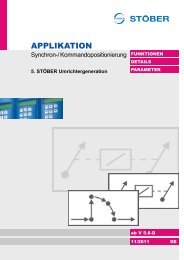
MDS<br />
POSIDRIVE ®<br />
MDS <strong>5000</strong><br />
Supplement documentation PROFIBUS DP<br />
It is essential to read and comply with this<br />
documentation and the<br />
• Mounting instruction (publ. no. 441688) and<br />
• Brief commissioning instruction (publ. no. 441690)<br />
MANAGEMENTSYSTEM<br />
certified by DQS according to<br />
DIN EN ISO 9001, DIN EN ISO 14001<br />
Reg-No. 000780 UM/QM<br />
PROFIBUS DP<br />
SV 5.1<br />
01/2005
POSIDRIVE® MDS <strong>5000</strong> – PROFIBUS DP<br />
Table of <strong>Co</strong>ntents<br />
STÖBER<br />
<strong>ANTRIEBSTECHNIK</strong><br />
TABLE OF CONTENTS<br />
1. Introduction 1<br />
2. Mounting 2<br />
3. Electrical Installation 3<br />
3.1 General Setup of a PROFIBUS System 3<br />
3.2 Suitable Bus Cables 4<br />
3.3 <strong>Co</strong>nnection of the Bus Cables to the Inverter 4<br />
4. Fundamentals of PROFIBUS 5<br />
4.1 PROFIDrive Profile Version 3 5<br />
4.2 <strong>Co</strong>mparison of the PROFIBUS Generations 5<br />
4.3 Data Transmission via PROFIBUS DP 6<br />
4.3.1 Possible <strong>Co</strong>mmunication 6<br />
4.3.2 User Data <strong>Co</strong>mmunication with MDS <strong>5000</strong> 7<br />
5. Bus Diagnosis / LEDs 8<br />
6. <strong>Co</strong>nfiguration of the Bus System 9<br />
6.1 GSD File 9<br />
6.2 Procedure for Simatic Step 7 9<br />
6.2.1 The HW-<strong>Co</strong>nfig 9<br />
6.2.2 SFC Calls for Data <strong>Co</strong>nsistency 10<br />
7. Process Data Transmission PZD 11<br />
7.1 Parameter Process Data Object (PPO) 11<br />
7.2 The Mapping 11<br />
7.2.1 Example PPO4 with 12-Byte PZD Area 12<br />
8. <strong>Co</strong>ntrol with <strong>Co</strong>ntrol and Status Bits 13<br />
9. Switchable Scaling 13<br />
10. Parameter <strong>Co</strong>mmunication 13<br />
10.1 Parameter Access with PKW1 Routine 13<br />
(New Protocol Only MDS <strong>5000</strong>)<br />
10.1.1 General Characteristics 13<br />
10.1.2 Block for the Acyclic Parameter Channel of the<br />
MDS <strong>5000</strong> (PKW1)<br />
11. Diagnostic Telegram 15<br />
12. Parameter Overview 15<br />
12.1 PROFIDRIVE Parameter 15<br />
12.2 PROFIBUS Parameter / Mapping / PKW1 15<br />
13. Appendix A - Detailed Protocol 18<br />
Organization of the PKW1 Protocol<br />
13.1 Parameter Jobs and Responses 18<br />
13.2 DPV1 Telegram Sequences 20<br />
13.2.1 DPV1 Telegram Frame 21<br />
14. Appendix B - PKW0 Telegram 23<br />
14.1 Parameter <strong>Co</strong>mmunication with PKW0 Rou- 23<br />
tine (<strong>Co</strong>mpatible with FAS/FDS/SDS 4000)<br />
14.1.1 Time Sequence of a PKW0 Service 25<br />
STÖBER <strong>ANTRIEBSTECHNIK</strong> Germany 26<br />
STÖBER <strong>ANTRIEBSTECHNIK</strong> International 28
POSIDRIVE® MDS <strong>5000</strong> – PROFIBUS DP<br />
1. Introduction<br />
STÖBER<br />
<strong>ANTRIEBSTECHNIK</strong><br />
1 INTRODUCTION<br />
To avoid problems during commissioning and operation, be sure to read all of the following before<br />
beginning commissioning:<br />
• Mounting Instructions for POSIDRIVE ® MDS <strong>5000</strong> (publ. no. 441688)<br />
• Short <strong>Co</strong>mmissioning Instructions for POSIDRIVE ® MDS <strong>5000</strong> (publ. no. 441690)<br />
• And this documentation<br />
Purpose of the manual<br />
This manual gives you information on the connection of the MDS <strong>5000</strong> inverter to the<br />
PROFIBUS DP fieldbus system. The structure of PROFIBUS and the principal<br />
procedures are also discussed.<br />
Goals of the manual:<br />
• Provide you with a basic knowledge of PROFIBUS communication with the MDS <strong>5000</strong><br />
• Offer you support when you design an application and configure communication<br />
Readers<br />
Target readers of this manual are users who are familiar with the control of drive systems<br />
and who have a basic knowledge of PROFIBUS.<br />
Other manuals<br />
For further information, see the following manuals.<br />
• Mounting Instructions (publ. no. 441688) for mounting the MDS family of devices.<br />
• Short <strong>Co</strong>mmissioning Instructions (publ. no. 441690) for a quick introduction to the<br />
operation of MDS family devices.<br />
• Application Manual (pupl. no. 441691) for a description of the applications which<br />
STÖBER <strong>ANTRIEBSTECHNIK</strong> has made available to you.<br />
• System Manual (publ. no. 441693) for a detailed description of the system and the<br />
option of free, graphical programming.<br />
Further support<br />
For questions on the use of the MDS system and its PROFIBUS interface which have<br />
not been answered by this manual, please call 0180 5 786323 and we will be glad to<br />
help.<br />
To make getting started with our software easier, we offer courses. <strong>Co</strong>ntact our training<br />
center at the following address.<br />
STÖBER <strong>ANTRIEBSTECHNIK</strong> <strong>GmbH</strong>+<strong>Co</strong>. <strong>KG</strong><br />
Training Center<br />
Kieselbronner Strasse 12<br />
75177 Pforzheim<br />
1
POSIDRIVE® MDS <strong>5000</strong> – PROFIBUS DP<br />
2. Mounting<br />
STÖBER<br />
<strong>ANTRIEBSTECHNIK</strong><br />
2 MOUNTING<br />
Introduction<br />
The DP<strong>5000</strong> fieldbus (PROFIBUS DP-V1) must first be installed before the MDS inverter<br />
can be integrated in a PROFIBUS system.<br />
We recommend ordering the option card with the inverter. If this is done, STÖBER<br />
<strong>ANTRIEBSTECHNIK</strong> will mount the DP<strong>5000</strong> before delivery.<br />
Proceed as shown below if the inverter must be upgraded with the option card.<br />
• Make sure that the device is isolated from the power supply.<br />
• Remove the dummy plate by unscrewing the two screws.<br />
• Remove the prepunched area (A) from the plate for the sub D plug connector.<br />
• Mount the plate on the board with the included UNC bolts (B).<br />
• Slide the fieldbus board (C) with the gold-contacted terminal surface (D) into the black<br />
terminal block.<br />
Do not touch the gold contact surface with your fingers (danger of corrosion).<br />
• Check that the board is positioned correctly.<br />
• Secure the covering plate with the two screws (E).<br />
B<br />
E<br />
A<br />
C<br />
D<br />
2
POSIDRIVE® MDS <strong>5000</strong> – PROFIBUS DP<br />
3. Electrical Installation<br />
STÖBER<br />
<strong>ANTRIEBSTECHNIK</strong><br />
3 ELECTRICAL INSTALLATION<br />
3.1 General Setup of a PROFIBUS System<br />
Introduction<br />
PROFIBUS DP consists of at least one bus segment. One segment consists of at least<br />
two but not more than 32 stations. They are all physically connected with a bus cable.<br />
One of the stations is the master. The master is the active station on PROFIBUS. It can<br />
send or request data to/from other stations. The slaves are the passive stations on<br />
PROFIBUS. They can only exchange data with the master when the master requests<br />
this.<br />
Terminating resistors must be placed at the beginning and the end of the bus.<br />
Master no. 1<br />
Slave<br />
no. 2<br />
Slave<br />
no. 3<br />
Slave<br />
no. 30<br />
Station (master or slave)<br />
Station with circuited terminating<br />
resistor<br />
Setup of a bus segment<br />
If more than 32 stations are to operate on a bus or the maximum line length of a bus<br />
segment is exceeded, several bus segments must be coupled via RS 485 repeaters. The<br />
maximum number of masters and slaves within one bus segment must be decreased by<br />
one for every repeater used. The maximum number of masters and slaves over the<br />
entire bus system is 126. The maximum line length depends on the baud rate being<br />
used. The table below gives you the maximum permissible lengths for one segment and<br />
for all segments.<br />
We strongly recommend NOT using stub lines in the setup. This is only permitted during<br />
commissioning.<br />
This bus system is usually set up with shielded, two-wire lines (RS 485). It can also be<br />
set up for special applications via fiber-optic conductors. STÖBER Antriebstechnik offers<br />
the coupling to the two-wire line. This permits a maximum distance of 10,000 m. When<br />
suitable measures are taken on the master side, slaves can be coupled or decoupled<br />
during operation without having to interrupt data communication on the bus.<br />
Baud Rate One Segment All Segments<br />
9.6 to 187.5 kbaud 1000 m 10000 m<br />
500 kbaud 400 m 4000 m<br />
1.5 Mbaud 200 m 2000 m<br />
3 to 12 Mbaud 100 m 1000 m<br />
These distances only apply with suitable bus cable!<br />
Segment 1<br />
Repeater<br />
Segment 2<br />
Repeater<br />
Segment 3<br />
3
POSIDRIVE® MDS <strong>5000</strong> – PROFIBUS DP<br />
3. Electrical Installation<br />
STÖBER<br />
<strong>ANTRIEBSTECHNIK</strong><br />
3.2 Suitable Bus Cables<br />
Introduction<br />
Specification of cable type A<br />
(PROFIBUS FMS and<br />
PROFIBUS DP)<br />
To ensure interference-free use of the above baud rates and distances, STÖBER<br />
<strong>ANTRIEBSTECHNIK</strong> recommends using cable type A described in PROFIBUS<br />
literature.<br />
• Wave resistance:<br />
• Cable capacity:<br />
• <strong>Co</strong>re cross section:<br />
• Cable type:<br />
• Loop resistance:<br />
• Signal attenuation:<br />
• Shielding:<br />
135 to 165 Ohm, at a measuring frequency of 3 to 20 MHz<br />
< 30 pF per meter<br />
> 0.34 mm²<br />
Twisted in pairs<br />
< 110 Ohm per km<br />
Max. of 9 dB over the entire length of the line segment<br />
Braided copper shield or braided shield and foil shield<br />
Use of other types of cables is not recommended since then only slower baud rates and<br />
reduced distances may be possible.<br />
3.3 <strong>Co</strong>nnection of the Bus Cables to the Inverter<br />
Introduction<br />
To connect PROFIBUS DP, the DP<strong>5000</strong> option module is equipped with a 9-pin, sub D<br />
socket plug connector with the pin allocation specified in the PROFIBUS standard.<br />
To connect the bus cable(s), we recommend the use of suitable bus connection plugs<br />
which are offered by various manufacturers especially for PROFIBUS DP.<br />
The incoming and the outgoing bus cable can be inserted and screwed down in these<br />
plug connectors. There is no outgoing bus cable for the last station. In this case the<br />
sliding switch on the plug is set to "on" to switch on the bus terminating resistors.<br />
Note: To ensure that bus termination functions correctly, the power supply may not be<br />
allowed to fail on the stations with circuited terminating resistors!<br />
To bypass the risk of a complete bus failure when the last station malfunctions, active<br />
bus terminating components can be used.<br />
MDS inverters of the device type "/L" are such components. They have a separate 24 V<br />
control section power supply. MDS inverters of device type "/H" provide the power for the<br />
electronics from 400 V.<br />
X200 – fieldbus PROFIBUS DP<br />
PIN 1 Signal / Function Description Circuiting<br />
1 nc Not connected<br />
2 nc Not connected<br />
3 B<br />
RxD / TxD-P<br />
(send/receive data - plus)<br />
PIN allocation in accordance with<br />
PROFIBUS standard (also for plug<br />
connectors with connectable terminating<br />
resistors)<br />
4 RTS Direction control for repeater (plus)<br />
5 GND Ground to +5 V<br />
6 +5 V Power for the terminating resistors<br />
7 nc Not connected<br />
8 A<br />
RxD / TxD-N<br />
(send/receive data - minus)<br />
9 nc Not connected<br />
1<br />
View of sub D socket<br />
4
POSIDRIVE® MDS <strong>5000</strong> – PROFIBUS DP<br />
4. Fundamentals of PROFIBUS<br />
STÖBER<br />
<strong>ANTRIEBSTECHNIK</strong><br />
4 FUNDAMENTALS OF PROFIBUS<br />
Introduction<br />
PROFIBUS is an open fieldbus standard for a wide variety of applications in<br />
manufacturing and process automation. The independence from manufacturers and the<br />
openness are ensured by international standard IEC 61158. For years now PROFIBUS<br />
has been one of the primary fieldbus systems on the international market.<br />
PROFIBUS DP is a fast and cost-optimized communication system for use at the field<br />
level in which a controller (PROFIBUS master) with several slaves (drives, IOs, and so<br />
on) performs cyclic data communication.<br />
4.1 PROFIDrive Profile Version 3<br />
Introduction<br />
There are three types: PROFIBUS FMS, PROFIBUS DP and PROFIBUS PA.<br />
PROFIBUS DP offers high-speed cyclic communication for small amounts of data.<br />
The PROFIBUS profile drive technology, called PROFIDrive, version 3, is a compatible<br />
continuation of the proven PROFIBUS profile for variable-speed drives, PROFIDrive,<br />
version 2. Today PROFIBUS communication is the standard for drive technology.<br />
In addition to the PROFIBUS standard, the PROFIDrive profile specifies uniform device<br />
reactions and access procedures for the drive data. One of the new functions of version<br />
3 is the parameter channel which uses the DP-V1 services of the acyclic communication.<br />
STÖBER <strong>ANTRIEBSTECHNIK</strong> offers all inverters of the POSIDRIVE ® MDS <strong>5000</strong> series<br />
the capacity to connect to PROFIBUS DP (DP = Decentral Periphery) via the<br />
PROFIDrive profile. This turns these devices into intelligent DP slaves which can be<br />
operated by a PROFIBUS master (controller, PLS, PC).<br />
Bus operation is possible up to a maximum speed of 12 Mbaud.<br />
Two LEDs indicate the function of the option board, the status of the data transmission<br />
and any malfunction (see chapter 5).<br />
When a PROFIBUS system is commissioned, the manuals/commissioning instructions of<br />
all involved components (DP master/controller, additional slaves, etc.) must be adhered<br />
to. For further information on PROFIBUS or PROFIDrive profile, go to www.profibus.com<br />
at the PROFIBUS User Organization.<br />
4.2 <strong>Co</strong>mparison of the PROFIBUS Generations<br />
Introduction<br />
This chapter summarizes the system characteristics applicable to drive technology and<br />
the system differences.<br />
Possible system installations<br />
Simultaneous operation of different<br />
inverter generations on one controller<br />
is possible and easy (see figure). Only<br />
when the new acyclic services are used<br />
are an MDS <strong>5000</strong> and an appropriate master<br />
required. The use of these<br />
services does not interfere with the operation<br />
of the other stations. When an older<br />
controller is used which does not support<br />
acyclic services, operation with cyclic<br />
data (PZD and PKW) can be used.<br />
MDS<br />
<strong>5000</strong><br />
SDS<br />
4000<br />
FDS<br />
4000<br />
FAS<br />
4000<br />
PROFIBUS Standard Properties New Features Meaning for MDS <strong>5000</strong><br />
DP-V0<br />
DP-V1<br />
Cyclic data communication<br />
(PZD + PKW)<br />
Cyclic data communication,<br />
identical with DP-V0<br />
- <strong>Co</strong>mpatible with FDS 4000, ...<br />
Acyclic services + alarm handling<br />
New parameter channel, available as per<br />
PROFIDrive V3<br />
5
POSIDRIVE® MDS <strong>5000</strong> – PROFIBUS DP<br />
4. Fundamentals of PROFIBUS<br />
STÖBER<br />
<strong>ANTRIEBSTECHNIK</strong><br />
4.3 Data Transmission via PROFIBUS DP<br />
4.3.1 Possible <strong>Co</strong>mmunication<br />
The MDS <strong>5000</strong> supports cyclic and acyclic services with the DP-V1 option. This provides<br />
a wide variety of possible ways to communicate.<br />
C2 - Master<br />
C2 - Master<br />
C1 - Master<br />
HMI<br />
1<br />
3<br />
2<br />
4<br />
Cyclic communication (1)<br />
Cyclic communication is the simple exchange of user data via the data exchange<br />
telegram. Time critical process data (PZD) are exchanged between a class-1 master<br />
(C1) and the drive controller with cyclic communication. Such data include, for example,<br />
reference and actual values, and control and status information. A routine for parameter<br />
communication (of the familiar PKW channel as with the FDS 4000) can be implemented<br />
within the cyclic communication. There is always exactly one C1 master in each<br />
PROFIBUS setup. This master reads the GSD file, configures the drives, starts<br />
PROFIBUS and runs the cyclic communication. The C1 master is usually the controller<br />
(arrow 1).<br />
Acyclic communication (2– 4)<br />
The acyclic services are available in DP-V1 for the transmission of new parameter jobs<br />
for controlling and monitoring the drives, parallel to true cyclic communication.<br />
In contrast to cyclic communication, acyclic communication data are only exchanged<br />
when necessary. Acyclic communication is performed either via an appropriate routine<br />
within cyclic communication (for PKW routine, see PROFIDrive profile version 2) or via<br />
the DP-V1 routines READ and WRITE. This permits the connection of commissioning<br />
tools as class-2 master (C2) to PROFIBUS. Many functions (e.g., reading malfunction<br />
memories, scope screens) are only offered by DP-V1.<br />
Several acyclic channels are available at the same time. The C1 master (the controller)<br />
maintains a continuously open connection to the MDS <strong>5000</strong> (MSAC1) which can be used<br />
as necessary by the controller program (arrow 2). In addition, the MDS <strong>5000</strong> provides<br />
the capacity for two connections (MSAC2) which can be established and used as<br />
necessary by C2 masters (e.g., an operator panel or a service PC).<br />
Time wise on PROFIBUS, the cyclic data always have the highest priority. During each<br />
data exchange cycle, the master inserts an acyclic telegram when necessary. This does<br />
not noticeably affect the speed of PROFIBUS.<br />
6
POSIDRIVE® MDS <strong>5000</strong> – PROFIBUS DP<br />
4. Fundamentals of PROFIBUS<br />
STÖBER<br />
<strong>ANTRIEBSTECHNIK</strong><br />
4.3.2 User Data <strong>Co</strong>mmunication with MDS <strong>5000</strong><br />
Introduction<br />
In addition to the description as seen by the bus in the previous chapter, the following<br />
differences exist from the point of view of the inverter.<br />
Process data channel PZD<br />
The process data channel is used for high-speed transmission of data which are used for<br />
controlling and monitoring the running process and which require a particularly short<br />
transmission time. When the bus system is configured, the selection of the PPO type<br />
specifies whether the cyclic parameter channel is to be used and how many bytes the<br />
process data channel will have.<br />
Parameter channels PKW<br />
All parameters can be read and changed with the parameter channels. First, the PKW1<br />
routine (which uses the acyclic services of PROFIBUS) specified by PROFIDrive version<br />
3 is available and, second, the old PKW0 routine (which is embedded in the cyclic data)<br />
defined by PROFIDrive version 2 is offered. Because of the comprehensive capabilities<br />
and the access to all inverter parameters without exception, the new PKW1 routine<br />
should be used if possible.<br />
The following transmission times show the throughput times through the PROFIBUS<br />
interface and the inverter.<br />
Transmission Channel MDS <strong>5000</strong> with Option DP-V1 <strong>5000</strong><br />
Process data reference values<br />
from the bus to the processing<br />
on the device<br />
<strong>Co</strong>mplete processing of a PKW0<br />
service<br />
PKW1 via acyclic services<br />
Depends on the configuration and setting of the<br />
parameter A150 cycle time.<br />
Approx. 16 to 64 ms<br />
Depends on the configuration!<br />
Approx. 16 to 64 ms<br />
Depends on the configuration!<br />
7
POSIDRIVE® MDS <strong>5000</strong> – PROFIBUS DP<br />
5. Bus Diagnosis / LEDs<br />
STÖBER<br />
<strong>ANTRIEBSTECHNIK</strong><br />
5 BUS DIAGNOSIS / LEDS<br />
Introduction<br />
The DP<strong>5000</strong> option module is equipped with a green and a red LED. The LEDs indicate<br />
communication-specific states. This permits the PROFIBUS status to be diagnosed on<br />
the device.<br />
Red LED<br />
Green LED<br />
Meaning / Measure<br />
Off<br />
Flashing<br />
Off<br />
Off<br />
No connection between the MDS <strong>5000</strong>0 and the<br />
PROFIBUS board (board was not recognized or has<br />
failed. See parameter E54 option module 1).<br />
PROFIBUS master stopped bus for more than 25 s (PLC<br />
in stop) or has failed or bus cable no longer connected<br />
(see parameter A84 PROFI-Baud).<br />
Off<br />
Off<br />
Flashing<br />
Flashing<br />
On<br />
Flashing<br />
Device is ready and is waiting for the PROFIBUS master<br />
to start or:<br />
When this state does not change although the PROFIBUS<br />
master has already attempted to establish a connection,<br />
this means that the applicable function blocks for<br />
PROFIBUS have not been downloaded to the inverter.<br />
Device was configured by PROFIBUS master and data<br />
communication was started.<br />
PROFIBUS master stopped the bus just a few seconds<br />
ago (< 25 s) (PLC in stop) or has failed or bus cable is no<br />
longer connected (see parameter A84 PROFI-Baud).<br />
The following diagnostic capabilities are available.<br />
• The two LEDs on the option board DP<strong>5000</strong><br />
• Parameter A84 PROFIBUS Baudrate<br />
• Parameter A86 PROFIBUS configuration<br />
• Parameter A85 PROFIBUS diagnosis (indication of internal inverter diagnostic<br />
information via the PROFIBUS interface).<br />
Parameter A85 is composed of the following bits.<br />
Bit Name Meaning for Bit = 1<br />
0 Shutdown-Fail<br />
Problems during shutting down the PROFIBUS driver<br />
software<br />
1 Data-Exchange<br />
PROFIBUS is in the state of cyclic data communication with<br />
this station.<br />
2 Wait for Param<br />
Station is waiting to be parameterized by the PROFIBUS<br />
master.<br />
3 Bus-Failure Error on PROFIBUS<br />
4 Acyc. Initiate 1 An acyclic connection has been established.<br />
5 Acyc. Initiate 2 A second acyclic connection has been established.<br />
6 MDS configured Station has been configured by the PROFIBUS master.<br />
7 Driver-Error Error in the PROFIBUS driver software<br />
8 Application ready MDS firmware is ready for a connection to PROFIBUS.<br />
9 LED red on The red LED of the DP<strong>5000</strong> is now on.<br />
10 LED green on The green LED of the DP<strong>5000</strong> is now on.<br />
8
POSIDRIVE® MDS <strong>5000</strong> – PROFIBUS DP<br />
6. <strong>Co</strong>nfiguration of the Bus System<br />
STÖBER<br />
<strong>ANTRIEBSTECHNIK</strong><br />
6 CONFIGURATION OF THE BUS SYSTEM<br />
6.1 GSD File<br />
Introduction<br />
Wiring all bus stations together is not sufficient to commission PROFIBUS DP. The<br />
following additional measures are required.<br />
• Different bus addresses must be set on the master and on all slaves.<br />
• With older slaves which are unable to find the baud rate automatically, the same baud<br />
rate must be set as on the master (MDS <strong>5000</strong> is able to find the baud rate<br />
automatically).<br />
• The master must be informed as to how many slaves are connected together with their<br />
characteristics and bus addresses.<br />
The baud rate must be set on the master under consideration of the segment lengths<br />
and the total distance of the bus.<br />
This work is performed on the master side using configuration software. This software<br />
must read the device master data files (GSD files) from all stations. The GSD files are<br />
like electronic data sheets which contain the information on the PROFIBUS<br />
characteristics such as supported baud rates, supported modules, and so on. They are<br />
provided by the manufacturer for each PROFIBUS device.<br />
The GSD file for the POSIDRIVE ® MDS <strong>5000</strong> has the designation STOE5005.GSD. The<br />
file can be downloaded from the Internet under www.stoeber.de.<br />
Note: The change in the PROFIBUS address of a slave is not accepted until the next<br />
device startup of the bus master. This was standardized to prevent the occurrence of<br />
dangerous system states due to double/non-addressed stations. Before switch-off, it is<br />
imperative that the drive data be stored on the inverter safe from a power failure with<br />
A00 save values = 1.<br />
6.2 Procedure for Simatic Step 7<br />
Introduction<br />
Different configuration software is used for different PROFIBUS masters. How this works<br />
with the SIMATIC Manager for the S7 in version 5.1 will be explained with an example.<br />
At least version 5.1 SP4 of Step 7 is required for use of DPV1 with Simatic Step 7. The<br />
S7 CPUs must also support DPV1. For whether the particular CPU supports DPV1, see<br />
the CPU characteristics under the hardware manager.<br />
6.2.1 The HW-<strong>Co</strong>nfig<br />
Introduction<br />
To link in the GSD file in the S7, open the menu "Extras" "Neue GSD Datei einbinden."<br />
Then display the GSD in the device catalog under "Extras" "Katalog<br />
Aktualisieren." This must done only once. After this, the MDS <strong>5000</strong> appears at the<br />
position as shown on the screen (on the following page) in the hardware catalog.<br />
HW-<strong>Co</strong>nfig in SIEMENS Step 7 may look like this:<br />
9
POSIDRIVE® MDS <strong>5000</strong> – PROFIBUS DP<br />
6. <strong>Co</strong>nfiguration of the Bus System<br />
STÖBER<br />
<strong>ANTRIEBSTECHNIK</strong><br />
HW-<strong>Co</strong>nfig<br />
6.2.2 SFC Calls for Data <strong>Co</strong>nsistency<br />
It is NOT necessary to reserve a separate memory area for the acyclic services (DPV1).<br />
This means that no PPO type must be selected which supports PKW. Every PPO type<br />
has this capability with the DPV1 protocol.<br />
Introduction<br />
To ensure data consistency on the bus, SIEMENS requires that SFCs 14 and 15 be<br />
used for data lengths longer than a double word. Direct accesses to the IO area via L<br />
PAW or L PEW are then NOT permitted. The SFCs must be called once per slave.<br />
Example<br />
Siemens SFCs 14/15<br />
10
POSIDRIVE® MDS <strong>5000</strong> – PROFIBUS DP<br />
7. Process Data Transmission PZD<br />
STÖBER<br />
<strong>ANTRIEBSTECHNIK</strong><br />
7 PROCESS DATA TRANSMISSION PZD<br />
7.1 Parameter Process Data Object (PPO)<br />
Introduction<br />
The MDS <strong>5000</strong> offers various telegram types in the GSD file for cyclic data transmission.<br />
The master selects one of the possibilities to configure the inverter and then start the bus.<br />
These possibilities are called parameter process data object (PPO types) and always<br />
contain the process data channel (PZD) and sometimes also a parameter channel<br />
(PKW0). The MDS <strong>5000</strong> provides five different PPO types to choose from for the<br />
establishment of this user data structure.<br />
To be able to use the functionality of process data transmission, the applicable blocks<br />
must be activated by the PC software POSITool. This is done by selecting a suitable<br />
application in user-prompted commissioning and then downloading it to the MDS <strong>5000</strong><br />
inverter. PPO types 3 or 4 fulfill all necessary requirements with the MDS <strong>5000</strong> since the<br />
PKW1 service no longer needs its own memory area and is thus not declared in the PPO<br />
type.<br />
PKW<br />
PZD<br />
PKE IND PWE PZD1, 2, 3, 4, 5, 6,<br />
Bytes<br />
PPO1<br />
PPO2<br />
PPO3<br />
PPO4<br />
PPO5<br />
PKW: Parameter ID value<br />
PZD: Process data<br />
PKE: Parameter ID<br />
IND: Subindex in byte 2. Byte 3 is reserved.<br />
PWE: Parameter value<br />
7.2 The Mapping<br />
Introduction<br />
Mapping manages the allocation of incoming data from the bus to the inverter parameters<br />
and vice versa. The following table describes the parameters required for mapping.<br />
STÖBER Parameter<br />
A90.0 PZD-SW 1. Mapping<br />
... 1. Mapped Parameter ...<br />
A90.5 5. Mapped Parameter<br />
A91.0 PZD-SW 2. Mapping<br />
... 1. Mapped Parameter ...<br />
A91.5 5. Mapped Parameter<br />
PNU /<br />
Subindex<br />
205A / 0<br />
...<br />
205A / 5<br />
205B / 0<br />
...<br />
205B / 5<br />
A93.0 PZD-SW Len 205C / 0<br />
Description<br />
Up to 6 parameters are selected here to which the received PZD data are copied<br />
with reference values (SW).<br />
Up to 6 additional parameters can be selected here as necessary in which the<br />
received PZD data are copied.<br />
Specifies the total data length in bytes which is to be accepted by PROFIBUS for<br />
the selected setting in A90 and A91. The value corresponds to the sum of the<br />
data lengths of the correctly set parameters which can be mapped on PZD. If no<br />
value or wrong values are entered in A90 and A91, the value 0 appears here (i.e.,<br />
no data are accepted by PROFIBUS).<br />
A94.0 PZD-IW 1. Mapping<br />
... 1. Mapped Parameter ...<br />
A94.5 5. Mapped Parameter<br />
A95.0 PZD-IW 2. Mapping<br />
... 1. Mapped Parameter ...<br />
A95.5 5. Mapped Parameter<br />
205E / 0<br />
...<br />
205E / 5<br />
205F / 0<br />
...<br />
205F / 5<br />
Up to 6 parameters are selected here which are copied as actual values (IW) to<br />
the PZD data to be sent to the master.<br />
Up to 6 additional parameters can be selected here which are copied as actual<br />
values to the PZD data to be sent to the master.<br />
11
POSIDRIVE® MDS <strong>5000</strong> – PROFIBUS DP<br />
7. Process Data Transmission PZD<br />
STÖBER<br />
<strong>ANTRIEBSTECHNIK</strong><br />
STÖBER Parameter<br />
PNU /<br />
Subindex<br />
Description<br />
A96.0 PZD-IW Len 2061 / 0<br />
Specifies the total data length in bytes which is to be transferred to PROFIBUS<br />
for the selected setting in A94 and A95. The value corresponds to the sum of<br />
the data lengths of the correctly set parameters which can be mapped on PZD.<br />
If no value or wrong values were entered in A94 and A95, the value 0 appears<br />
here (i.e., no data are accepted by PROFIBUS).<br />
Note:<br />
Caution! Mapping does not become active until the bus station (MDS <strong>5000</strong>) has<br />
performed a new start on the bus. Please save the values before the new start with the<br />
function "A00 save values."<br />
7.2.1 Example PPO4 with 12-Byte PZD Area<br />
Receiving area of the MDS <strong>5000</strong><br />
Parameter Value Description Length [Byte]<br />
A90.0 A180 Device control byte 1<br />
A90.1 I211 Motion control byte 1<br />
A90.2 I210 <strong>Co</strong>ntrol word command posi 2<br />
A90.3 I213 Target position 4<br />
A90.4 I230 Override 2<br />
Sending area of the MDS <strong>5000</strong><br />
Total length 10<br />
In reserve 2<br />
Parameter Value Description Length [Byte]<br />
A94.0 E200 Device status byte 1<br />
A94.1 I201 Motion status byte 1<br />
A94.2 I200 Status word command posi 2<br />
A94.3 I203 Actual position 4<br />
A94.4 E100 Actual speed 2<br />
Total length 10<br />
In reserve 2<br />
When the parameters A90/A94 are set as described here, the data are automatically<br />
mapped by the inverter from and to the parameters.<br />
12
POSIDRIVE® MDS <strong>5000</strong> – PROFIBUS DP<br />
STÖBER<br />
<strong>ANTRIEBSTECHNIK</strong><br />
8. <strong>Co</strong>ntrol with <strong>Co</strong>ntrol and Status Bits<br />
8 CONTROL WITH CONTROL AND STATUS BITS<br />
Introduction<br />
The control and status words depend on their use and the STÖBER template used. The<br />
demands on the control word differ for the individual applications (e.g., command<br />
positioning, fast reference value, etc.) and can be found in the particular application<br />
documentation.<br />
9 SWITCHABLE SCALING<br />
Introduction<br />
Some of the MDS parameters can be scaled for the fieldbus transmission in two ways:<br />
Scaled as standard or with the native raw resolution of the MDS <strong>5000</strong>. The scaling can<br />
be set with the parameter A100. With A100=0, the values are scaled as standard. With<br />
A100=1, the raw values are transferred to PROFIBUS. In this case there is no scaling to<br />
user-defined or physical units and the values are forwarded in the internal-inverter format<br />
instead. This relieves the main processor of the MDS <strong>5000</strong>.<br />
Note: When this parameter is switched, this may cause a change in the length of the<br />
user data which are transmitted. This happens when position values are transferred via<br />
the bus. Position reference and actual values are shorted to 32 bits when being scaled<br />
for the bus. However, the device uses a rough accuracy of 64 bits. The assignment of<br />
the data on the PLC is then no longer correct. The received/sent data length can be<br />
checked in parameters A93 / A97.<br />
10 PARAMETER COMMUNICATION<br />
10.1 Parameter Access with PKW1 Routine (New Protocol Only MDS <strong>5000</strong>)<br />
10.1.1 General Characteristics<br />
• 16-bit address each for parameter number and subindex<br />
• Transmission of whole arrays, areas thereof or the entire parameter description<br />
• Transmission of different parameters in one access (multi-parameter jobs)<br />
• Only one parameter job is processed at a time (no pipelining).<br />
• A parameter job/rely must fit in one data block (max. of 240 bytes). The maximum<br />
length of the data blocks can be less than 240 bytes due to slave characteristics or the<br />
bus configuration.<br />
• "Multi-parameter" jobs are defined for optimized, simultaneous access to different<br />
parameters (e.g., HMI screens).<br />
• There are no cyclic parameter jobs, in contrast to PKW0 (of DP-V0).<br />
10.1.2 Block for the Acyclic Parameter Channel of the MDS <strong>5000</strong> (PKW1)<br />
To make use of the acyclic parameter channel to the MDS <strong>5000</strong> in an S7 program as<br />
simple as possible, STÖBER Antriebstechnik offers an easy-to-use FB. The block should<br />
be circuited as shown below.<br />
FB50 acyclic PKW communication circuitry<br />
Type Parameter Description Example<br />
IN LAADR Hardware address, PZD area from HW <strong>Co</strong>nfig (convert to hex) =DW#16#100 (256 dec)<br />
ID 0 no job / 1 read / 2 write =B#16#1<br />
Par_lenght<br />
Length of the parameter, 1 byte/ 2 words/3 Dwords<br />
(must only be provided for write jobs)<br />
=B#16#3<br />
Par_Num PNU from parameter list =W#16#200A<br />
Par_Index Index from parameter list =B#16#0<br />
Axis Axis selection (0 – 4) =B#16#0<br />
OUT Busy Job still running<br />
Ready Job concluded correctly<br />
Req_Error Error occurred<br />
Errornum Number of the error that occurred<br />
INOUT Data - Parameter value<br />
Start - Starts the job<br />
Reset - Resets the block when there are problems<br />
13
POSIDRIVE® MDS <strong>5000</strong> – PROFIBUS DP<br />
10. Parameter <strong>Co</strong>mmunication<br />
STÖBER<br />
<strong>ANTRIEBSTECHNIK</strong><br />
The start bit is reset automatically after a query. When the ready bit is set and no Req_Err<br />
is queued, this means that the parameter was read/written successfully. When necessary,<br />
the next job can then be started. The block locks itself as long as it is still being<br />
processed. When parameter changes occur (write=1), the parameter length must be<br />
specified. Normally, the length is 4 bytes (corresponds to B#16#3). In exceptional cases,<br />
the length must be specified as per the table in the appendix.<br />
When Req_Error is queued, the error can be specified in more detail with the variable<br />
error number in table 2.<br />
Error numbers in PKW1 parameter responses<br />
Error<br />
Number<br />
Meaning Use for Additional Info<br />
00 hex Illegal parameter number Access to a non-existent parameter 0<br />
01 hex Parameter value cannot be changed.<br />
02 hex<br />
Upper or lower value limit has been<br />
exceeded.<br />
Modification access to a parameter value that cannot<br />
be changed<br />
Modification access with value outside the value<br />
limits<br />
Subindex<br />
Subindex<br />
03 hex Wrong subindex Access to a non-existent subindex Subindex<br />
04 hex No array Access with subindex to a non-indexed parameter 0<br />
05 hex Wrong data type<br />
11 hex<br />
Job cannot be executed due to<br />
operating state.<br />
Modification access with value which does not match<br />
the data type of the parameter<br />
Access is not possible for temporary reasons which<br />
are not specified further<br />
65 hex Wrong job ID - -<br />
66 hex Internal communication failed Example: no configuration loaded<br />
67 hex Reserved<br />
77 hex Access not permitted by user level<br />
79 hex Scaling error<br />
0<br />
0<br />
7C hex<br />
7D hex<br />
Value in definition gap (see selection).<br />
<strong>Co</strong>llision with other values<br />
83 hex Error in pre-read function<br />
84 hex Error in post-write function<br />
Rest<br />
Reserved<br />
14
POSIDRIVE® MDS <strong>5000</strong> – PROFIBUS DP<br />
11. Diagnostic Telegram<br />
STÖBER<br />
<strong>ANTRIEBSTECHNIK</strong><br />
11 DIAGNOSTIC TELEGRAM<br />
12 PARAMETER OVERVIEW<br />
Not supported at this time.<br />
Introduction<br />
All parameters of the inverter are available as communication objects via the PKW<br />
service (PKW0 or PKW1).<br />
12.1 PROFIDRIVE Parameter<br />
PNU<br />
[in hex]<br />
Subindex<br />
Parameter Name<br />
STÖBER-<br />
Address<br />
Data<br />
Type<br />
Value/Meaning<br />
918 0 Node address A83 5 Bus address<br />
964 0 Device identification / manufacturer - 6 (U16) 267 dec = STÖBER<br />
964 1 Device identification / device type - 6 (U16) 4D44 hex = ASCII "MD" for MDS <strong>5000</strong><br />
964 2 Device identification / version - 6 (U16) 0500 hex = V 5.00<br />
964 3 Device identification / firmware year - 6 (U16)<br />
964 4 Device identification / firmware day / month - 6 (U16)<br />
965 0 PROFIBUS profile number -<br />
0303 hex for PROFIDrive profile version<br />
3<br />
12.2 PROFIBUS Parameter / Mapping / PKW1<br />
Introduction<br />
All STÖBER-specified drive parameters are stored as communication objects in the<br />
parameter number area from 2000 hex to 5FFF hex .<br />
Formula for the generation of: parameter number, axis and subindex:<br />
For all groups A.. - Z..:<br />
Parameter number (PNU) = 2000 hex + 200 hex * group (A=0, B=1, ...) + row.<br />
Subindex = Element number for record or array (e.g., A00 0 = start,<br />
1=progress, 2=result)<br />
Axis = Number of the physical axis. Values between 0 and 3 can be used<br />
here.<br />
(When the table contains "global," the same memory location is addressed in every<br />
axis.)<br />
List of the primary communication parameters for the commissioning of MDS <strong>5000</strong> on PROFIBUS:<br />
STÖBER-<br />
Address<br />
A00<br />
...<br />
A83<br />
A84<br />
A85<br />
A86<br />
Axes<br />
Global<br />
Global<br />
Global<br />
Global<br />
Global<br />
Parameter Name<br />
Save values: When this parameter is activated, the inverter<br />
saves the current configuration and the parameter values in the<br />
Paramodule. After power-off, the inverter starts with the saved<br />
configuration. If the configuration data on the inverter and<br />
Paramodul are identical, only the parameters are saved<br />
(speeds up the procedure).<br />
Bus address: Specifies the device address for operation with<br />
fieldbus. A83 has no effect on communication via X3 with<br />
POSITool or another USS master.<br />
PROFIBUS baudrate: When operated with MDS <strong>5000</strong> with<br />
option board "PROFIBUS DP," the baud rate found on the bus<br />
is indicated.<br />
PROFIBUS diagnostic: Indication of internal inverter<br />
diagnostic information on the PROFIBUS DP interface.<br />
PROFIBUS configuration: The inverter offers various<br />
ways (PPO types) to transfer cyclic user data via PROFIBUS<br />
DP. These can be configured in the GSD file STOE5005.gsd<br />
on the controller (bus master). This indication parameter can<br />
be used to check which of the possible configurations was<br />
chosen.<br />
PNU<br />
[hex]<br />
Number of<br />
Data<br />
Elements for<br />
Type<br />
Subindex (0,...)<br />
Value /<br />
Meaning<br />
2000 3 0, 0, 0<br />
2053 1 5 3<br />
2054 1 5<br />
2055 1 6<br />
2056 1 5<br />
0=9600<br />
Baud, ...<br />
bit field<br />
with 16 bits<br />
chosen<br />
configuration<br />
15
POSIDRIVE® MDS <strong>5000</strong> – PROFIBUS DP<br />
12. Parameter Overview<br />
STÖBER<br />
<strong>ANTRIEBSTECHNIK</strong><br />
STÖBER-<br />
Address<br />
A90<br />
A91<br />
A93<br />
A94<br />
A95<br />
A97<br />
A100<br />
Axes<br />
Global<br />
Global<br />
Global<br />
Global<br />
Global<br />
Global<br />
Global<br />
Parameter Name<br />
PZD Setpoint Mapping: The target parameters are<br />
entered in A90/A91 for the reference values/control bits which<br />
are sent by the PLC to the MDS <strong>5000</strong> via PROFIBUS.<br />
Example: When A90.0=A180 is entered, this means that the<br />
first byte (length of A180) which is received by the bus is<br />
transferred to parameter A180. Subsequent data are<br />
transferred in the same way to the entered parameters. It is<br />
absolutely necessary that the length of the entered parameters<br />
be known.<br />
PZD Setpoint Mapping: The target parameters are<br />
entered in A90/A91 for the reference values/control bits which<br />
are sent by the PLC to the MDS <strong>5000</strong> via PROFIBUS.<br />
Example: When entered in A90.0=A180, this means that the<br />
first byte (length of A180) which is received by the bus is<br />
transferred to parameter A180. The subsequent data are<br />
transferred in the same way to the entered parameters. It is<br />
absolutely necessary that the length of the entered parameters<br />
be known.<br />
PNU<br />
[hex]<br />
Number of<br />
Data<br />
Elements for<br />
Type<br />
Subindex (0,...)<br />
Value /<br />
Meaning<br />
205A 6 7 see above<br />
205B 6 7 „<br />
PZD Setpoint Len: Indicator parameter which indicates the<br />
length in bytes of the expected process data with reference<br />
205C<br />
values (data from PROFIBUS master to inverter) for the current<br />
1 5 „<br />
parameterization.<br />
PZD ActValue Mapping: The source parameters are<br />
entered in A94/A95 which contain the actual values/status bits<br />
of the MDS <strong>5000</strong> which are sent to the PLC via PROFIBUS.<br />
Example: When entered in A94.0=E200, this means that the<br />
first byte (length of E200) which is transferred by the bus<br />
contains the contents of parameter E200. The subsequent data<br />
are transferred via the bus in the same way. It is absolutely<br />
necessary that the length of the entered parameters be known.<br />
PZD ActValue Len: Indicator parameter which indicates the<br />
length in bytes of the current process data with actual values<br />
(data from inverter to PROFIBUS master) for the current<br />
parameterization.<br />
Fieldbusscaling: The selection is made here between<br />
internal raw values and whole numbers for the<br />
representation/scaling of process data values during<br />
transmission via PZD channel. Regardless of this setting, the<br />
representation is always the whole number via PKW channel<br />
and the non cyclic parameter channel.<br />
Caution: When "0:integer" is parameterized (scaled values),<br />
the runtime load increases significantly and it may become<br />
necessary to increase A150 Cycle time to avoid the fault<br />
"57:runtime usage" or "35:Watchdog."<br />
With few exceptions, the PKW channel is always transferred in<br />
scaled format.<br />
205E 6 7 „<br />
205F 6 7 „<br />
2061 1 5 „<br />
2064 1 5<br />
0:standard<br />
1:raw value<br />
16
POSIDRIVE® MDS <strong>5000</strong> – PROFIBUS DP<br />
12. Parameter Overview<br />
STÖBER<br />
<strong>ANTRIEBSTECHNIK</strong><br />
STÖBER-<br />
Address<br />
Axes<br />
Parameter Name<br />
PNU<br />
[hex]<br />
Number of<br />
Data<br />
Elements for<br />
Type<br />
Subindex (0,...)<br />
Value /<br />
Meaning<br />
A109<br />
Global<br />
PZD-Timeout: To keep the inverter from continuing with the<br />
last received reference values after a failure of PROFIBUS or<br />
the PROFIBUS master, process data monitoring should be<br />
activated. The RX block monitors the regular receipt of<br />
process data telegrams (PZD) which the PROFIBUS master<br />
sends cyclically during normal operation. The A109 PZD-<br />
Timeout parameter is used to activate this monitoring function.<br />
A time is set here in milliseconds. The default setting is 65535.<br />
This value and also the value 0 mean that monitoring is<br />
inactive. This is recommended while the inverter is being<br />
commissioned on PROFIBUS and for service and<br />
maintenance work.<br />
Monitoring should only be activated for the running process<br />
during which a bus master cyclically sends process data to the<br />
MDS. The monitoring time must be adapted to the maximum<br />
total cycle time on PROFIBUS plus a sufficient reserve for<br />
possible delays. Sensible values are usually between 30 and<br />
300 msec.<br />
When process data monitoring is triggered on the inverter, the<br />
fault "52:communication" is triggered.<br />
206D<br />
* The A109 PZD-Timeout parameter is also used for<br />
communication via USS protocol for the USS-PZD telegram.<br />
List for quick location of the correct parameter numbers based on the STÖBER address:<br />
Area No.<br />
Group<br />
Start PNU<br />
[in hex]<br />
End PNU<br />
[in hex]<br />
1 A 2000 21FF<br />
2 B 2200 23FF<br />
3 C 2400 25FF<br />
4 D 2600 27FF<br />
5 E 2800 29FF<br />
6 F 2A00 2BFF<br />
7 G 2C00 2DFF<br />
8 H 2E00 2FFF<br />
9 I 3000 31FF<br />
10 J 3200 33FF<br />
11 K 3400 35FF<br />
12 L 3600 37FF<br />
13 M 3800 39FF<br />
14 N 3A00 3BFF<br />
15 O 3C00 3DFF<br />
16 P 3E00 3FFF<br />
17 Q 4000 41FF<br />
18 R 4200 43FF<br />
19 S 4400 45FF<br />
20 T 4600 47FF<br />
21 U 4800 49FF<br />
22 V 4A00 4BFF<br />
23 W 4C00 4DFF<br />
24 X 4E00 4FFF<br />
25 Y <strong>5000</strong> 51FF<br />
26 Z 5200 53FF<br />
Reserved - 5400 5FFF<br />
17
POSIDRIVE® MDS <strong>5000</strong> – PROFIBUS DP<br />
13. Appendix A - Detailed Protocol Organization of the PKW1 Protocol<br />
STÖBER<br />
<strong>ANTRIEBSTECHNIK</strong><br />
13 APPENDIX A - DETAILED PROTOCOL ORGANIZATION OF THE PKW1 PROTOCOL<br />
13.1 Parameter Jobs and Responses<br />
Introduction<br />
This chapter provides detailed information on the organization of the protocol of the<br />
PKW1 standard which is only required when no S7 controller is used with our FB50.<br />
A parameter job consists of three areas:<br />
• Job header: ID for the job and the number of parameters which are accessed.<br />
Addressing of an axis for multiple-axis drives.<br />
• Parameter address: Addressing of a parameter. The parameter address only appears<br />
in the job, not in the response.<br />
• Parameter value: There is one area for the parameter value for each parameter.<br />
Parameter values appear only in either the job or in the response, depending on the<br />
job ID.<br />
DPV1 parameter job:<br />
Telegram Portion Byte Function Info<br />
Job header 0 Job reference<br />
1 Job ID<br />
2 Axis<br />
3 Number of parameters Fixed at 1<br />
1st Parameter address 4 Attribute<br />
5 Number of elements Fixed at 1<br />
6+7 Parameter number<br />
8+9 Subindex<br />
1st Parameter value (only for writing) 10 Format<br />
11 Number of values<br />
12 to xx Values<br />
DPV1 parameter response:<br />
Telegram Portion Byte Function Info<br />
Response header 0 Job reference, echoed<br />
1 Response ID<br />
2 Axis, echoed<br />
3 Number of parameters Fixed at 1<br />
1st Parameter value (only for writing) 4 Format<br />
5 Number of values<br />
6 to xx Values<br />
Explanation of the fields<br />
Job header:<br />
• Job reference<br />
Unique identification of the job/response pair for the master. The master changes the<br />
job reference with each new job (e.g., modulo 255). The slave echoes the job<br />
reference in the response.<br />
• Job ID<br />
Two IDs are defined:<br />
01 hex Request/read parameter<br />
02 hex Change parameter<br />
• Response ID<br />
Echoing of job ID with additional info whether execution positive or negative<br />
01 hex Request parameter, positive<br />
81 hex Request parameter, negative (job could not be executed, either partially<br />
or completely).<br />
02 hex Change parameter, positive<br />
82 hex Change parameter, negative (job could not be executed either partially or<br />
completely).<br />
With a negative response, an error number is transferred instead of the parameter<br />
value.<br />
18
POSIDRIVE® MDS <strong>5000</strong> – PROFIBUS DP<br />
13. Appendix A - Detailed Protocol Organization of the PKW1 Protocol<br />
STÖBER<br />
<strong>ANTRIEBSTECHNIK</strong><br />
• Axis<br />
Addressing of an axis when a POSISwitch ® is used. This means that the same DP-V1<br />
connection can be used to access different axis with a separate parameter number<br />
area for each on the drive.<br />
Value range: 0 to 3.<br />
• Number of parameters<br />
Specifies the number of subsequent areas, parameter address and/or parameter value<br />
for multiple parameter jobs. "Number of parameters" = 1 for simple jobs.<br />
Value range: 1 to 37 (restricted by DP-V1 telegram length).<br />
Parameter address:<br />
• Attribute<br />
Type of object which is being accessed<br />
10 hex = Value<br />
20 hex = Description, not implemented<br />
30 hex = Text, not implemented<br />
• Number of elements<br />
Number of array elements which are being accessed. Value range: 0, 1 to 117<br />
(restricted by DP-V1 telegram length)<br />
Special case: Number of elements = 0:<br />
- Access to values: Recommended for non-indexed parameters for compatible<br />
conversion of the parameter job to a PKW job in accordance with PROFIDrive profile<br />
version 2 (differentiation between "request/change parameter value" and<br />
"request/change parameter value (array)").<br />
• Parameter number PNU<br />
Addresses the parameter which is being accessed. Value range: 1 to 65535. See<br />
parameter list.<br />
• Subindex<br />
Addresses first array element of the parameter or text array or the descriptive element<br />
which is being accessed. Value range: 0 to 65535. See parameter list.<br />
Parameter value:<br />
• Format<br />
Must only be supplied in exceptional cases for write jobs.<br />
01 hex Boolean<br />
02 hex Integer 8<br />
03 hex Integer 16<br />
04 hex Integer 32<br />
05 hex Unsigned 8<br />
06 hex Unsigned 16<br />
07 hex Unsigned 32<br />
08 hex Floating point<br />
11 Double<br />
17 Posi 64<br />
28 String 8<br />
29 String 16<br />
30 String 80<br />
31 U8 Array64<br />
40 Zero<br />
41 Byte<br />
42 Word<br />
43 Double word (standard)<br />
44 Error<br />
• Number of values: When a multiple-parameter job is not being used, a 1 should<br />
appear here.<br />
• Values: <strong>Co</strong>ntents of the parameter<br />
• Error numbers<br />
19
POSIDRIVE® MDS <strong>5000</strong> – PROFIBUS DP<br />
13. Appendix A - Detailed Protocol Organization of the PKW1 Protocol<br />
STÖBER<br />
<strong>ANTRIEBSTECHNIK</strong><br />
Error numbers in PKW0 parameter responses<br />
Error<br />
Number<br />
Meaning<br />
Use for<br />
00 hex Illegal parameter number Access to a non-existent parameter 0<br />
01 hex Parameter value cannot be changed.<br />
02 hex<br />
Upper or lower value limit has been<br />
exceeded.<br />
Modification access to a parameter value that<br />
cannot be changed<br />
Modification access with value outside the value<br />
limits<br />
Additional<br />
Information<br />
Subindex<br />
Subindex<br />
03 hex Wrong subindex Access to a non-existent subindex Subindex<br />
04 hex No array Access with subindex to a non-indexed parameter 0<br />
05 hex Wrong data type<br />
Modification access with value which does not<br />
match the data type of the parameter<br />
0<br />
11 hex<br />
Job cannot be executed due to<br />
operating state.<br />
Access is not possible for temporary reasons which<br />
are not specified further<br />
65 hex Wrong job ID - -<br />
66 hex Internal communication failed Example: no configuration loaded<br />
67 hex Reserved<br />
77 hex Access not permitted by user level<br />
79 hex Scaling error<br />
0<br />
7C hex<br />
Value in definition gap (see selection).<br />
7D hex<br />
<strong>Co</strong>llision with other values<br />
83 hex Error in pre-read function<br />
84 hex Error in post-write function<br />
Remainder Reserved<br />
13.2 DPV1 Telegram Sequences<br />
The data in the write request correspond to the parameter job. The data in the read<br />
response correspond to the parameter response.<br />
Master<br />
DPV1<br />
Slave<br />
Parameter job<br />
Write.req DB47<br />
with data (parameter job)<br />
Write.res<br />
without data<br />
Parameter job<br />
Read. req DB47<br />
without Daten<br />
Read.res(-)<br />
without data<br />
Parameter<br />
processing<br />
Parameter response<br />
Read.req DB47<br />
without data<br />
Read.res<br />
with data (parameter response)<br />
Parameter response<br />
Telegram sequence via DPV1<br />
20
POSIDRIVE® MDS <strong>5000</strong> – PROFIBUS DP<br />
13. Appendix A - Detailed Protocol Organization of the PKW1 Protocol<br />
STÖBER<br />
<strong>ANTRIEBSTECHNIK</strong><br />
13.2.1 DPV1 Telegram Frame<br />
Normal case:<br />
The following four DPV1 telegrams are used to transmit a parameter job/parameter<br />
response pair:<br />
Transmission of the parameter job in a DPV1 write request:<br />
DPV1 write header<br />
DPV1 data (length)<br />
Function_Num = 5F hex (write) Slot_Number = ...<br />
Index = 47<br />
Length = (data)<br />
Parameter job ...<br />
...<br />
1) Abbreviated acknowledgment of the parameter job with the DPV1 write response<br />
(without data):<br />
DPV1 write header<br />
Function_Num = 5F hex (write)<br />
Index = (echoed)<br />
Slot_Number = (echoed)<br />
Length = (echoed)<br />
2) Request for the parameter response in a DPV1 read request (without data):<br />
DPV1 read header<br />
Function_Num = 5E hex (read) Slot_Number = ...<br />
Index = 47<br />
Length = MAX<br />
3) Transmission of the parameter response in the DPV1 read response:<br />
DPV1 read header<br />
DPV1 data (length)<br />
Function_Num = 5E hex (read)<br />
Index = (echoed)<br />
Parameter response ...<br />
...<br />
Slot_Number = (echoed)<br />
Length = (data)<br />
Meaning and use of the elements<br />
in the DPV1 header<br />
Errors<br />
• Function_Num<br />
ID for DPV1 service (read, write, error)<br />
• Slot_Number<br />
DPV1: In the request: Addressing of a real or virtual module on the slave. In the<br />
response: Echoed.<br />
PROFIDrive: No evaluation<br />
• Index (data block)<br />
DPV1: In the request: Addressing of a data block on the slave. In the response:<br />
Echoed.<br />
PROFIDrive: Data block number 47 defines for parameter jobs and responses.<br />
• Length<br />
DPV1: In the write request and read response, the length of the transferred data in<br />
bytes.<br />
PROFIDrive: Length of the parameter job/response.<br />
DPV1: In the read request, the requested length of a data block.<br />
PROFIDrive: Maximum possible length.<br />
DPV1: In the write response, the data length accepted by the slave.<br />
PROFIDrive: Echoing of the length from the write request.<br />
In case an error occurs, a DPV1-read or write request is answered with an error<br />
response.<br />
4) DPV1 error response:<br />
Function_Num = DF hex (Error write)<br />
Error_Decode = 128 (DPV1)<br />
= DE hex (Error read)<br />
DPV1 error<br />
Error_<strong>Co</strong>de_2 =<br />
Error_<strong>Co</strong>de_1<br />
(don't care ⇒ always = 0)<br />
• Error_Decode<br />
DPV1: ID, to be interpreted like Error_<strong>Co</strong>de1/2.<br />
PROFIDrive: Always 128 (DPV1 codes)<br />
• Error_<strong>Co</strong>de_1<br />
DPV1: Division into error class (4 bits) and error code (4 bits).<br />
• PROFIDrive<br />
Use of certain numbers.<br />
• Error_<strong>Co</strong>de_2<br />
DPV1: User-specific.<br />
PROFIDrive: Not used (always = 0).<br />
21
POSIDRIVE® MDS <strong>5000</strong> – PROFIBUS DP<br />
13. Appendix A - Detailed Protocol Organization of the PKW1 Protocol<br />
STÖBER<br />
<strong>ANTRIEBSTECHNIK</strong><br />
DPV1 error class and code for PROFIDrive<br />
Error_Class<br />
(from DPV1 specs)<br />
0 hex ... 9 hex = reserved<br />
A hex = application<br />
Error_<strong>Co</strong>de<br />
(from DPV1 specs)<br />
0 hex = read error<br />
1 hex = write error<br />
2 hex = module failure<br />
3 hex to 7 hex = reserved<br />
8 hex = version conflict<br />
9 hex = feature not supported<br />
A hex to F hex = user-specific<br />
PROFIDrive Application<br />
B hex = access 0 hex = invalid index B0 hex = Data block does not exist. DB47: Parameter jobs not<br />
supported.<br />
1 hex = write length error<br />
2 hex = invalid slot<br />
3 hex = type conflict<br />
4 hex = invalid area<br />
-<br />
C hex = resource<br />
D hex ...F hex = user-specific<br />
5 hex = state conflict B5 hex = Access to DB47 temporarily impossible due to internal<br />
processing state.<br />
6 hex = access denied<br />
7 hex = invalid range B7 hex = Write DB47 with error in DB47 header.<br />
8 hex = invalid parameter<br />
9 hex = invalid type<br />
A hex to F hex = user-specific<br />
0 hex = read constrain conflict<br />
1 hex = write constrain conflict<br />
2 hex = resource busy<br />
3 hex = resource unavailable<br />
4 hex..7 hex = reserved<br />
8 hex..F hex = user-specific<br />
-<br />
22
POSIDRIVE® MDS <strong>5000</strong> – PROFIBUS DP<br />
14. Appendix B - PKW0 Telegram<br />
STÖBER<br />
<strong>ANTRIEBSTECHNIK</strong><br />
14 APPENDIX B - PKW0 TELEGRAM<br />
14.1 Parameter <strong>Co</strong>mmunication with PKW0 Routine (<strong>Co</strong>mpatible with FAS/FDS/SDS 4000)<br />
Introduction<br />
A = 0<br />
B = 1<br />
C = 2<br />
D = 3<br />
E = 4<br />
F = 5<br />
G = 6<br />
H = 7<br />
I = 8<br />
J = 9<br />
K = 10<br />
L = 11<br />
M = 12<br />
N = 13<br />
O = 14<br />
P = 15<br />
Q = 16<br />
R = 17<br />
S = 18<br />
T = 19<br />
U = 20<br />
V = 21<br />
W = 22<br />
X = 23<br />
Y = 24<br />
Z = 25<br />
When PPO type 1 or 2 is selected during configuration of PROFIBUS DP, the "parameter<br />
ID value (PKW0)" routine defined in PROFIDRIVE is available for parameter<br />
communication. However, not all parameters, displays and actions of the inverter can be<br />
accessed. Excluded are parameters with a number greater than 255, a length greater<br />
than 32 bits (text parameters) or indexed parameters with an index greater than 19. The<br />
axis is selected via A11.1 as shown below.<br />
A11.1 = 0 Axis 1 or 2 depending on PNU<br />
A11.1 = 1 (=2/3) Axis 13 or 4 depending on PNU<br />
A11.1 itself can be accessed via:<br />
PNU dec = 1000 + 20 * 0 + 1 = 1001<br />
Subindex = 11<br />
In the old PROFIDrive profile version 2, only 11 bits were provided for a parameter<br />
number. That severely restricted the available address area. Fourth-generation STÖBER<br />
Antriebstechnik inverters locate their parameters in the area of the PNU between 1000<br />
dec to 1999 dec.<br />
To be able to offer downwards compatibility, the old PKW0 routine is still available with<br />
the same addresses. The entire scope of parameters available today with the various<br />
data types cannot be imaged on this, however.<br />
Specification of parameter number and subindex for the access via PROFIBUS can be<br />
created from the coordinates of the particular parameter in the menu of the inverter. The<br />
following rules apply:<br />
PNU dec = 1000 + 20 * letter of the menu coordinate + 500<br />
for axis 2 (used to be parameter record 2) + 1 * index.<br />
Subindex dec = <strong>Co</strong>unting value of the menu coordinate.<br />
The parameters from the groups B.. to G.. exist once in axis 1 and then again in axis 2.<br />
The menu only contains one coordinate. For access via PROFIBUS, the parameter<br />
numbers for the parameters for axis 1 are selected from 1000 to 1499 and for axis 2<br />
starting at 1500.<br />
The bits for the parameter number, job and response ID are located within the two-byte<br />
parameter ID. (The SPM bit for spontaneous message processing is not supported.)<br />
The master sends to the inverter the job ID, the parameter number, the subindex and,<br />
during write accesses, the new value. The MDS then answers with the response ID,<br />
parameter number, subindex and, during read accesses, with the current value. All<br />
values are represented as double words (4 bytes in length) on PROFIBUS. This means<br />
that the master no longer needs to recognize and distinguish between the data sizes of<br />
byte, word and double word.<br />
The job ID is used to differentiate between reset, write and read jobs. The master (PLC)<br />
must repeat the same job at least until the applicable response arrives from the MDS.<br />
Bytes for parameter ID value (PKW)<br />
Byte<br />
PKE IND<br />
PWE<br />
01234567<br />
Bit 151413121110 9 8 7 6 5 4 3 2 1 0<br />
Job ID Parameter number (PNU)<br />
SPM<br />
PKE : Parameter ID<br />
IND : Subindex in byte 2; byte 3 ist reserved.<br />
PWE : Parameter value<br />
23
POSIDRIVE® MDS <strong>5000</strong> – PROFIBUS DP<br />
14. Appendix B - PKW0 Telegram<br />
STÖBER<br />
<strong>ANTRIEBSTECHNIK</strong><br />
Job ID<br />
Meaning<br />
0 No job (reset job)<br />
1 Request parameter value (read)<br />
3 Change parameter value (write)<br />
Remainder<br />
Do not use!<br />
The MDS responds to the same bit positions with the response ID. The response ID<br />
remains unchanged until the current job is finished. The job ID must be maintained<br />
constant as long as this has not occurred.<br />
Response ID<br />
Error numbers in PKW0 parameter responses<br />
Meaning<br />
0 No response or also: OK for job ID "no job"<br />
2 Transfer parameter value (sent to master)<br />
7 Job cannot be executed.<br />
The inverter deletes all response bytes together with the response ID 0. With response<br />
ID 2, the parameter number and the subindex are echoed from the job in the response.<br />
The MDS continues sending the complete response until the master formulates a new<br />
job. With read accesses to indicator values of the MDS, the MDS always cyclically sends<br />
new current values until the master formulates a new job.<br />
When the MDS responds with 7: Job cannot be executed, the least significant byte of the<br />
parameter value (PWE) (thus in byte 7) contains the applicable error number.<br />
Error<br />
Number<br />
Meaning Use for Extra Info<br />
00 hex Illegal parameter number Access to non-existent parameter 0<br />
01 hex Parameter value cannot be changed.<br />
Modification access to a parameter value which cannot<br />
be changed.<br />
Subindex<br />
02 hex Lower or upper value limit exceeded.<br />
Modification access with value outside the value limits.<br />
.<br />
Subindex<br />
03 hex Wrong subindex Access to a non-existent subindex. Subindex<br />
04 hex No array Access with subindex to a non-indexed parameter. 0<br />
05 hex Wrong data type<br />
Modification access with value which does not match<br />
the data type of the parameter.<br />
0<br />
11 hex<br />
Job cannot be executed due to operating<br />
state.<br />
Access is not possible for temporary reasons not<br />
specified in more detail.<br />
65 hex Wrong job ID - -<br />
66 hex Internal communication interrupted. Example: No configuration loaded.<br />
67 hex Reserved<br />
77 hex Access not permitted by user level.<br />
79 hex Scaling error<br />
7C hex Value in definition gap (check selection).<br />
7D hex <strong>Co</strong>llision with other values<br />
83 hex Error in pre-read function<br />
84 hex Error in post-write function<br />
Remainder Reserved<br />
0<br />
Other rules for job/response<br />
processing:<br />
• To ensure that the MDS with PROFIBUS interface always stops responding to the last<br />
job and is ready for the next job, the job ID "no job" must be briefly sent.<br />
• Transmission on the bus takes place in Motorola format (Big-endian): High parameter<br />
value is sent first both within a word and the words within a double word.<br />
• When no information is needed from the PKW interface during cyclic operation, the job<br />
ID should be set to "no job."<br />
24
POSIDRIVE® MDS <strong>5000</strong> – PROFIBUS DP<br />
14. Appendix B - PKW0 Telegram<br />
STÖBER<br />
<strong>ANTRIEBSTECHNIK</strong><br />
14.1.1 Time Sequence of a PKW0 Service<br />
Introduction<br />
In the example below, the parameter D00 SW-Accel from parameter record 2 is to be<br />
changed to the value 300 ms/3000 Rpm for a controller which can handle transfer<br />
commands for the 16-bit format.<br />
Take values from parameter list:<br />
PNU = 1060 decimal = 424 hex , subindex = 1 (see chapter 9)<br />
Parameter value 300 decimal = 12C hex .<br />
Step<br />
1<br />
2<br />
3<br />
4<br />
6<br />
Set PLC Output Byte<br />
(xx = Old <strong>Co</strong>ntent)<br />
Byte: 0 1 2 3 4 5 6 7<br />
HexValue: 00 00 00 00 xx xx xx xx<br />
Byte: 0 1 2 3 4 5 6 7<br />
HexValue: 00 00 00 00 xx xx xx xx<br />
Byte: 0 1 2 3 4 5 6 7<br />
HexValue: 00 00 00 00 00 00 01 2C<br />
Byte: 0 1 2 3 4 5 6 7<br />
HexValue: 00 00 01 00 00 00 01 2C<br />
Byte: 0 1 2 3 4 5 6 7<br />
HexValue: 34 24 00 00 00 00 01 2C<br />
Explanation<br />
Delete job ID and reserved byte 3.<br />
Wait until response ID contains 0 in input bytes of MDS. Mask out<br />
bits 4 to 7 and check for 0. The PNU of the last job might still be<br />
located in the other bits and in byte 1. Wait time depends on the bus<br />
token time (number of stations).<br />
Expand parameter value 12 C to 4 bytes and enter in bytes 4 to 7.<br />
Enter subindex 1 in byte 2.<br />
Enter parameter number 424 hex in bits 0 to 10 of the PKE and enter<br />
job ID in bits 12 to 15. Bit 11 remains 0.<br />
7 Byte: 0 1 2 3 4 5 6 7<br />
HexValue: 34 24 00 00 00 00 01 2C<br />
Wait until a response arrives in input byte. For example:<br />
Byte: 0 1 2 3 4 5 6 7<br />
HexValue: 24 24 00 00 00 00 00 00<br />
The 2 in byte 0 is the response ID "transfer parameter value." This<br />
means the new value was correctly transferred by the MDS.<br />
8<br />
Byte: 0 1 2 3 4 5 6 7<br />
HexValue: 00 00 00 00 00 00 xx xx<br />
Delete job ID again to shorten the wait time for the next PKW<br />
service.<br />
25
STÖBER <strong>ANTRIEBSTECHNIK</strong> - Deutschland<br />
STÖBER <strong>ANTRIEBSTECHNIK</strong><br />
Hauptverwaltung: STÖBER <strong>ANTRIEBSTECHNIK</strong> <strong>GmbH</strong> & <strong>Co</strong>. <strong>KG</strong> Fon 07231 582-0<br />
Postfach 910103 Fax 07231 582-1000<br />
75091 Pforzheim eMail sales@stoeber.de<br />
Vertriebsgebiet Nordwest:<br />
Kieselbronner Straße 12<br />
24-Stunden-Service-Nr.<br />
75177 Pforzheim 0180 5 786323<br />
Vanity-No:<br />
0180 5 STOEBER<br />
Zentrale STÖBER <strong>ANTRIEBSTECHNIK</strong> <strong>GmbH</strong> & <strong>Co</strong>. <strong>KG</strong> Fon 02302 98494-0<br />
Friedrich-Ebert-Str. 85 Fax 02302 98494-50<br />
58454 Witten eMail TB_DO@stoeber.de<br />
Zugehörige Technische Büros:<br />
Norddeutschland STÖBER <strong>ANTRIEBSTECHNIK</strong> <strong>GmbH</strong> & <strong>Co</strong>. <strong>KG</strong> Fon 04164 811904<br />
20000 - 23919<br />
Stefan Hildebrandt Fax 04164 811905<br />
24000 - 29999<br />
Bei den roten Höfen 4 eMail TB_ND@stoeber.de<br />
21698 Harsefeld<br />
Münster STÖBER <strong>ANTRIEBSTECHNIK</strong> <strong>GmbH</strong> & <strong>Co</strong>. <strong>KG</strong> Fon 02552 610271<br />
33000 - 33599<br />
Markus Merker Fax 02552 610272<br />
33600 - 33899<br />
Grottenkamp 28 eMail TB_MS@stoeber.de<br />
33900 - 33999<br />
48565 Steinfurt<br />
48000 - 49999<br />
59200 - 59329<br />
59470 - 59699<br />
Dortmund West STÖBER <strong>ANTRIEBSTECHNIK</strong> <strong>GmbH</strong> & <strong>Co</strong>. <strong>KG</strong> Fon 02302 98494-0<br />
40000 - 41999<br />
Jürgen Volkmuth Fax 02302 98494-50<br />
46000 - 47999<br />
Friedrich-Ebert-Str. 85 eMail TB_DO@stoeber.de<br />
<strong>5000</strong>0 - 50999<br />
58454 Witten<br />
52000 - 53999<br />
Dortmund Ost STÖBER <strong>ANTRIEBSTECHNIK</strong> <strong>GmbH</strong> & <strong>Co</strong>. <strong>KG</strong> Fon 02302 98494-0<br />
42000 - 45999<br />
Detlef Mock Fax 02302 98494-50<br />
51000 - 51999<br />
Friedrich-Ebert-Str. 85 eMail TB_DO@stoeber.de<br />
57000 - 59199<br />
58454 Witten<br />
59330 - 59469<br />
59700 - 59999<br />
Hannover STÖBER <strong>ANTRIEBSTECHNIK</strong> <strong>GmbH</strong> & <strong>Co</strong>. <strong>KG</strong> Fon 05481 903946<br />
30000 - 32999<br />
Arne Hülsmeier Fax 05481 903974<br />
34330 - 34549<br />
Holbeinstraße 43 eMail TB_H@stoeber.de<br />
37000 - 37199<br />
49525 Lengerich<br />
37400 - 38799<br />
Vertriebsgebiet Mitte:<br />
Zentrale STÖBER <strong>ANTRIEBSTECHNIK</strong> <strong>GmbH</strong> & <strong>Co</strong>. <strong>KG</strong> Fon 07231 582-0<br />
Postfach 910103, 75091 Pforzheim<br />
Kieselbronner Straße 12, 75177 Pforzheim<br />
Fax<br />
eMail<br />
07231 582-1000<br />
sales@stoeber.de<br />
Zugehörige Technische Büros:<br />
Saar-Pfalz STÖBER <strong>ANTRIEBSTECHNIK</strong> <strong>GmbH</strong> & <strong>Co</strong>. <strong>KG</strong> Fon 06126 989406<br />
54000 - 56999<br />
Roland Dillmann Fax 06126 55499<br />
6<strong>5000</strong> - 66919<br />
Black & Decker-Str. 1 eMail TB_ID@stoeber.de<br />
67200 - 67319<br />
65510 Idstein<br />
67500 - 67999<br />
Wiesbaden STÖBER <strong>ANTRIEBSTECHNIK</strong> <strong>GmbH</strong> & <strong>Co</strong>. <strong>KG</strong> Fon 06126 989405<br />
34000 - 34329<br />
Jens Thomas Fax 06126 55499<br />
34550 - 36399<br />
Black & Decker-Str. 1 eMail TB_ID@stoeber.de<br />
37200 - 37299<br />
65510 Idstein<br />
60000 - 64999<br />
Vertriebsgebiet Süd:<br />
Zentrale STÖBER <strong>ANTRIEBSTECHNIK</strong> <strong>GmbH</strong> & <strong>Co</strong>. <strong>KG</strong> Fon 07231 582-0<br />
Postfach 910103, 75091 Pforzheim<br />
Kieselbronner Straße 12, 75177 Pforzheim<br />
Fax<br />
eMail<br />
07231 582-1000<br />
sales@stoeber.de<br />
Stand: 06.05.2004
STÖBER <strong>ANTRIEBSTECHNIK</strong> - Deutschland<br />
Zugehörige Technische Büros:<br />
STÖBER <strong>ANTRIEBSTECHNIK</strong><br />
Pforzheim Süd STÖBER <strong>ANTRIEBSTECHNIK</strong> <strong>GmbH</strong> & <strong>Co</strong>. <strong>KG</strong> Fon 07231 582-1229<br />
71000 - 71299<br />
Günter Großmann Fax 07231 582-1349<br />
75100 - 75399<br />
Postfach 910103, 75091 Pforzheim eMail TB_PFSued@stoeber.de<br />
Kieselbronner Straße 12, 75177 Pforzheim<br />
Pforzheim Nord STÖBER <strong>ANTRIEBSTECHNIK</strong> <strong>GmbH</strong> & <strong>Co</strong>. <strong>KG</strong> Fon 07231 582-1217<br />
70000 - 70999<br />
Philipp Gerstner Fax 07231 582-1349<br />
71300 - 71499<br />
Postfach 910103, 75091 Pforzheim eMail TB_PFNord@stoeber.de<br />
71600 - 71999<br />
Kieselbronner Straße 12, 75177 Pforzheim<br />
74000 - 74172<br />
74300 - 74399<br />
75400 - 75999<br />
Nordbaden STÖBER <strong>ANTRIEBSTECHNIK</strong> <strong>GmbH</strong> & <strong>Co</strong>. <strong>KG</strong> Fon 07231 582-1149<br />
66920 - 67199<br />
Stefan Rotterdam Fax 07231 582-1349<br />
67320 - 67499<br />
Postfach 910103, 75091 Pforzheim eMail TB_NB@stoeber.de<br />
68000 - 69999<br />
Kieselbronner Straße 12, 75177 Pforzheim<br />
74173 - 74299<br />
74600 - 75099<br />
76600 - 76999<br />
97860 - 97999<br />
Südbaden STÖBER <strong>ANTRIEBSTECHNIK</strong> <strong>GmbH</strong> & <strong>Co</strong>. <strong>KG</strong> Fon 07231 582-1114<br />
72190 - 72299<br />
Daniel Lohse Fax 07231 582-1349<br />
76000 - 76599<br />
Postfach 910103, 75091 Pforzheim eMail TB_SB@stoeber.de<br />
77000 - 77999<br />
Kieselbronner Straße 12, 75177 Pforzheim<br />
78090 - 78149<br />
79000 - 79999<br />
Reutlingen STÖBER <strong>ANTRIEBSTECHNIK</strong> <strong>GmbH</strong> & <strong>Co</strong>. <strong>KG</strong> Fon 07121 994035<br />
72000 - 72189<br />
Wilhelm Haydt Fax 07121 994036<br />
72300 - 72999<br />
Gerh.-Hauptmann-Str. 53 eMail TB_RT@stoeber.de<br />
78000 - 78089<br />
72793 Pfullingen<br />
78150 - 78999<br />
88000 - 89299<br />
89570 - 89999<br />
Württemberg Nord-Ost STÖBER <strong>ANTRIEBSTECHNIK</strong> <strong>GmbH</strong> & <strong>Co</strong>. <strong>KG</strong> Fon 07333 950773<br />
71500 - 71599<br />
Klaus Buschko Fax 07333 950774<br />
73000 - 73999<br />
Meisenweg 25 eMail TB_WNO@stoeber.de<br />
74400 - 74599<br />
72589 Westerheim<br />
89500 - 89569<br />
München STÖBER <strong>ANTRIEBSTECHNIK</strong> <strong>GmbH</strong> & <strong>Co</strong>. <strong>KG</strong> Fon 09191 616890<br />
80000 - 84999<br />
Udo Cyrol Fax 09191 734538<br />
85200 - 87999<br />
Industriestraße 20 a eMail TB_M@stoeber.de<br />
89300 - 89499<br />
91353 Hausen<br />
94000 - 94999<br />
Nürnberg STÖBER <strong>ANTRIEBSTECHNIK</strong> <strong>GmbH</strong> & <strong>Co</strong>. <strong>KG</strong> Fon 09191 734537<br />
8<strong>5000</strong> - 85199<br />
Wolfgang Lukas Fax 09191 734538<br />
90000 - 93999<br />
Industriestraße 20 a eMail TB_N@stoeber.de<br />
9<strong>5000</strong> - 96499<br />
91353 Hausen<br />
97000 - 97859<br />
Vertriebsgebiet Ost:<br />
Zentrale STÖBER <strong>ANTRIEBSTECHNIK</strong> <strong>GmbH</strong> & <strong>Co</strong>. <strong>KG</strong> Fon 07231 582-0<br />
Postfach 910103, 75091 Pforzheim<br />
Kieselbronner Straße 12, 75177 Pforzheim<br />
Fax<br />
eMail<br />
07231 582-1000<br />
sales@stoeber.de<br />
Zugehörige Technische Büros:<br />
Berlin / Brandenburg STÖBER <strong>ANTRIEBSTECHNIK</strong> <strong>GmbH</strong> & <strong>Co</strong>. <strong>KG</strong> Fon 033438 5731<br />
06000 - 06599<br />
Bernd Weise Fax 033438 5732<br />
06730 - 07299<br />
Werneuchener Weg 9 eMail TB_BR@stoeber.de<br />
10000 - 19999<br />
15345 Altlandsberg<br />
23920 - 23999<br />
38800 - 39999<br />
Lichtenstein STÖBER <strong>ANTRIEBSTECHNIK</strong> <strong>GmbH</strong> & <strong>Co</strong>. <strong>KG</strong> Fon 037204 2985<br />
00000 - 05999<br />
Jürgen Stolper Fax 037204 2986<br />
06600 - 06729<br />
Günsbacher Straße 4 eMail TB_LI@stoeber.de<br />
07300 - 09999<br />
09350 Lichtenstein<br />
36400 - 36999<br />
37300 - 37399<br />
96500 - 96999<br />
98000 - 99999<br />
Stand: 06.05.2004
STÖBER <strong>ANTRIEBSTECHNIK</strong> - International<br />
STÖBER <strong>ANTRIEBSTECHNIK</strong><br />
Austria STÖBER <strong>ANTRIEBSTECHNIK</strong> <strong>GmbH</strong> Phone +43 7613 76000<br />
Fabriksplatz 1 Fax +43 7613 76009<br />
4662 Steyrermühl eMail office@stoeber.at<br />
France STÖBER S.a.r.l. Phone +33 4 72132438<br />
47, rue Maurice Flandin Fax +33 4 72132457<br />
69003 Lyon eMail mail@stober.fr<br />
Great Britain STOBER DRIVES LTD. Phone +44 1992 709710<br />
Unit 9, Abbeymead Industrial Park Fax +44 1992 714111<br />
Brooker Road, Waltham Abbey eMail mail@stober.co.uk<br />
Essex EN9 1HU<br />
Italy STÖBER TRASMISSIONI S. r. l. Phone +39 02 93909-570<br />
Via Risorgimento, 8 Fax +39 02 93909-325<br />
20017 Mazzo di Rho (Milano) eMail info@stoeber.it<br />
Korea DAE KWANG STOEBER CO. LTD. Phone +82 31 4347047<br />
2 Ma 301-3 Sihwa Industrial <strong>Co</strong>mplex, Fax +82 31 4347048<br />
1704-3 Jungwang dong, Siheung city, eMail dkstoeber@stoeber.co.kr<br />
Gyunggi do, Korea<br />
Postcode 429-845<br />
Poland STOEBER POLSKA Phone +48 71 3207417<br />
ul.H.Kamienskiego 201-219 Fax +48 71 3207417<br />
51-126 Wroclaw eMail biuro@stoeber.pl<br />
USA STOBER DRIVES INC. Phone +1 606 7595090<br />
1781 Downing Drive Fax +1 606 7595045<br />
Maysville, KY 41056 eMail sales@stober.com<br />
Belgium VAN DOREN - PILLE N. V. Phone +32 9 2521309<br />
Industrieterrein De Prijkels Fax +32 9 2522374<br />
Venecoweg 25 eMail info@vandorenpille.be<br />
9810 Nazareth<br />
Brasil FRAPHE INDUSTRIA E COMERCIO Phone +55 35 34355965<br />
Rua Bairro Da Ponte Alta S/N Fax +55 35 34353887<br />
37640-000 Extrema - MG eMail fraphe@fraphe.com.br<br />
Bulgaria Z & M PRIVATE COMPANY Phone +359 2 9865855<br />
5, Angel Kantchev Str. Fax +359 2 9865916<br />
1000 Sofia eMail zandm@techno-link.com<br />
China WK-INTERSALES BEIJING Phone +86 10 65906425 + 26<br />
German Centre Fax +86 10 65906785<br />
Unit 0525-0530, Landmark Tower 2 eMail stoeber@wk-intersales.com<br />
8 North Dongsanhuan Road<br />
Chaoyang District<br />
Beijing 100004<br />
<strong>Co</strong>lombia SOCOMEX LTDA. Phone +57 2856105 / +57 2856496<br />
Apdo. Aereo 11606 +57 2856336<br />
Santafe de Bogota D. C. Fax +57 13350487<br />
Denmark EEGHOLM A/S Phone +45 73 121212<br />
Grundtvigs Allé 165-169 Fax +45 73 121213<br />
P. O. Box 190 eMail eegholm@eegholm.dk<br />
6400 Sønderborg<br />
Stand: 19.07.2004
STÖBER <strong>ANTRIEBSTECHNIK</strong> - International<br />
STÖBER <strong>ANTRIEBSTECHNIK</strong><br />
Finland EIE MASKIN OY Phone +358 19 2461642<br />
PL 80 Fax +358 19 2461643<br />
10600 Tammisaari eMail eie@eie.fi<br />
Hungary BDI Hungary Ltd. Phone +36 1 2311010<br />
Fóti Street 141, Bldg 37. Fax +36 1 2311030<br />
1046 Budapest eMail bdi-hun@elender.hu<br />
the Netherlands MIJNSBERGEN B. V. Phone +31 297 285821<br />
Postbus 166 Fax +31 297 272326<br />
3640 AD Mijdrecht eMail info@mijnsbergen.nl<br />
Norway ELMEKO AS Phone +47 67 572270<br />
Postbox 80 Fax +47 67 572280<br />
1306 Baerum Postterminal eMail elmeko@elmeko.no<br />
Peru POWERMATIC S. A. Phone +51 1 3490184 / 3494011<br />
Av. Los Ingenieros 333 Fax +51 1 4370073<br />
Ate-Vitarte, Lima 3 eMail powermatic@terra.com.pe<br />
Philippines LEELENG COMMERCIAL, INC. Phone +63 2 2418901 to 05<br />
387 - 393 Dasmariñas St. Fax +63 2 2414060<br />
P. O. Box 480 eMail leeleng@manila.vasia.com<br />
Manila<br />
South Africa BEARING MAN LTD. Phone +27 11 6201500<br />
P. O. Box 33431 Fax +27 11 6201775<br />
Jeppestown 2043 eMail sales@bearing_man.co.za<br />
Spain TAHFER COMERCIAL, S. A. Phone +34 91 6193424<br />
Jesus, 27 Fax +34 91 6197792<br />
28917 - LA FORTUNA eMail tahfercom@tahfer.com<br />
S.p.i.t. KOOM s. I. Phone +34 94 3297809<br />
Camino Caserio Parada, 25 Fax +34 94 3297810<br />
20015 San Sebastián eMail koom@spitkoom.com<br />
Sweden EIE MASKIN AB Phone +46 8 7278800<br />
Postfach 7 Fax +46 8 7278899<br />
12421 Bandhagen eMail eie@eie.se<br />
Switzerland INDUR <strong>ANTRIEBSTECHNIK</strong> AG Phone +41 61 2792900<br />
Margarethenstraße 87 Fax +41 61 2792910<br />
4008 Basel eMail info@indur.ch<br />
Thailand GERMAN ENGINEERING & Phone +66 2 3153331 / 3153332<br />
MACHINERY CO., LTD. Fax +66 2 3153663<br />
399 Moo 17 Bangna Trad Rd. Km 23 eMail sale-ge@mweb.co.th<br />
Bangsaothong Sub District<br />
10540 Samutprakarn<br />
Turkey HARTEK Sanayigi Ticaret Ltd. Sti Phone +90 216 5406026<br />
Y. Dudullu Mah. Alptekin Fax +90 216 5406030<br />
Sk. No: 2 Kat: 2 eMail o.aydin@hartek.net<br />
34775 ÜMRANIYE - ISTANBUL<br />
Stand: 19.07.2004
Additional information under:<br />
http://www.stoeber.de<br />
STÖBER . . . The Drive for your Automation<br />
STÖBER <strong>ANTRIEBSTECHNIK</strong><br />
<strong>GmbH</strong> + <strong>Co</strong>. <strong>KG</strong><br />
GERMANY<br />
Kieselbronner Strasse 12 · 75177 Pforzheim<br />
Postfach 910103 · 75091 Pforzheim<br />
Fon +49 (0) 7231 582-0, Fax +49 (0) 7231 582-1000<br />
Internet: http://www.stoeber.de / E-Mail: mail@stoeber.de<br />
Presented by:<br />
© 2005 STÖBER <strong>ANTRIEBSTECHNIK</strong> <strong>GmbH</strong> + <strong>Co</strong>. <strong>KG</strong><br />
Publication no. 441687.00.01 · 01.2005<br />
- Subject to technical change without prior notice -