Power source and testing cable how to connect fcar car diagnostic tool
FCAR F3 auto diagnostic scanners power supply has four kinds of ways,(take F3-G auto diagnostic scanners example)
FCAR F3 auto diagnostic scanners power supply has four kinds of ways,(take F3-G auto diagnostic scanners example)

Create successful ePaper yourself
Turn your PDF publications into a flip-book with our unique Google optimized e-Paper software.
<strong>Power</strong> <strong>source</strong> <strong>and</strong> <strong>testing</strong> <strong>cable</strong> <strong>how</strong> <strong>to</strong> <strong>connect</strong> <strong>f<strong>car</strong></strong> <strong>car</strong><br />
<strong>diagnostic</strong> <strong>to</strong>ol<br />
FCAR F3 au<strong>to</strong> <strong>diagnostic</strong> scanners power supply has four kinds of ways,(take<br />
F3-G au<strong>to</strong> <strong>diagnostic</strong> scanners example) as s<strong>how</strong>n in Figure 3.1.1<br />
.<strong>Power</strong> supply by power adapter<br />
.<strong>Power</strong> supply by main <strong>testing</strong> <strong>cable</strong>, connec<strong>to</strong>r <strong>and</strong> vehicle <strong>diagnostic</strong><br />
socket<br />
.<strong>Power</strong> supply by <strong>connect</strong>ion of cigarette lighter with vehicle<br />
.<strong>Power</strong> supply by <strong>connect</strong>ion of battery terminal line with vehicle<br />
battery<br />
Figure 3.1.1<br />
Cable Connection Method<br />
Option of power:<br />
If the <strong>diagnostic</strong> socket not with power supply,<br />
Can choose 1 3 4 in 3.1.1 one of these three<br />
power <strong>connect</strong>ion methods <strong>to</strong> provide power<br />
for <strong>car</strong> <strong>diagnostic</strong> scanners.<br />
If the <strong>diagnostic</strong> socket with power, you do not<br />
need <strong>to</strong> <strong>connect</strong> another power cord.<br />
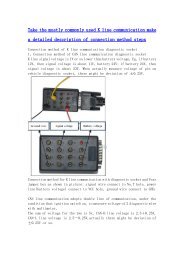
The <strong>connect</strong>ion of <strong>testing</strong> <strong>cable</strong> as s<strong>how</strong>n in Figure 3.1.2<br />
Figure 3.1.2<br />
The prerequisites for vehicle:<br />
1 Confirm the <strong>diagnostic</strong> socket location, shape, <strong>and</strong> whether need for<br />
external power supply.<br />
2 Select the appropriate connec<strong>to</strong>r base on vehicle model <strong>and</strong> shape of
<strong>diagnostic</strong> socket.<br />
3 Connect one end of the main <strong>testing</strong> line <strong>to</strong> the other end of main unit<br />
<strong>diagnostic</strong> connec<strong>to</strong>r.<br />
4 Plug <strong>diagnostic</strong> connec<strong>to</strong>r that <strong>connect</strong>ed with the main <strong>testing</strong> line in<strong>to</strong><br />
the vehicle <strong>diagnostic</strong> socket.<br />
5 Confirm that main unit with power <strong>and</strong> start up.<br />
Remark: Diagnostic interface in Fig.3.1.2 is st<strong>and</strong>ard OBD-II interface,<br />
when <strong>connect</strong>ing, 2 ends of main <strong>testing</strong> <strong>cable</strong> are required <strong>to</strong> separately<br />
<strong>connect</strong> with OBD-II connec<strong>to</strong>r <strong>and</strong> F<strong>car</strong> au<strong>to</strong> <strong>diagnostic</strong> scanners, plug<br />
OBD-II connec<strong>to</strong>r in<strong>to</strong> vehicle <strong>diagnostic</strong> socket <strong>to</strong> finish <strong>connect</strong>ion.