Installation service by Step-Four Tips from the experts
Installation service by Step-Four Tips from the experts
Installation service by Step-Four Tips from the experts

Create successful ePaper yourself
Turn your PDF publications into a flip-book with our unique Google optimized e-Paper software.
Model making<br />
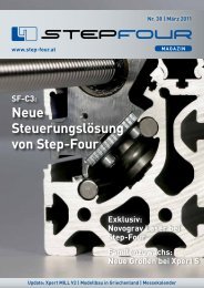
The original „Fairey Rotodyne“ of <strong>the</strong><br />
50s unfortunately never quite past <strong>the</strong><br />
prototype status.<br />
The frames and spar caps were milled<br />
<strong>from</strong> 4 mm poplar plywood.<br />
The rotor tower with <strong>the</strong> mounted mechanism.<br />
The tail with <strong>the</strong> swivelling vertical tail<br />
fins consist of a spar-ribbed construction<br />
made <strong>from</strong> milled 3 mm poplar plywood<br />
parts.<br />
Thanks to CAD and CNC, retrospectively<br />
constructed parts also fit perfectly,<br />
such as <strong>the</strong> servo holder above.<br />
Many parts of <strong>the</strong> cockpit construction<br />
were designed as a basis on <strong>the</strong> CAD<br />
and <strong>the</strong>n milled.<br />
The wings are also rib constructions<br />
with standing crest spar.<br />
The engine nacelles consist of inner<br />
parts constructed and mounted as housings<br />
– all drawn and milled, of course.<br />
After a construction period of eight<br />
months, <strong>the</strong> body shell was practically<br />
complete.<br />
The rotor mechanism unfortunately<br />
proved to be insufficiently stable<br />
enough for flight.<br />
STEP-FOUR | March 2010<br />
11