
Create successful ePaper yourself
Turn your PDF publications into a flip-book with our unique Google optimized e-Paper software.
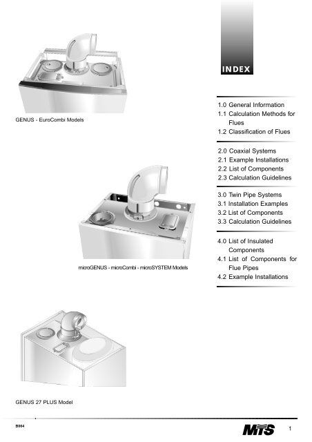
INDEX<br />
GENUS - EuroCombi Models<br />
1.0 General Information<br />
1.1 Calculation Methods for<br />
Flues<br />
1.2 Classification of Flues<br />
2.0 Coaxial Systems<br />
2.1 Example Installations<br />
2.2 List of Components<br />
2.3 Calculation Guidelines<br />
3.0 Twin Pipe Systems<br />
3.1 Installation Examples<br />
3.2 List of Components<br />
3.3 Calculation Guidelines<br />
microGENUS - microCombi - microSYSTEM Models<br />
4.0 List of Insulated<br />
Components<br />
4.1 List of Components for<br />
Flue Pipes<br />
4.2 Example Installations<br />
GENUS 27 PLUS Model<br />
B064<br />
1
Flue Pipe<br />
Accessories<br />
Wall-hung Gas Boilers<br />
with Sealed Combustion<br />
Chamber<br />
Manufactured within<br />
the European Comunity
1.0 General Information This catalogue contains all of the information needed for the proper<br />
installation and use of the exhaust discharge/air intake <strong>flue</strong> systems.<br />
Moreover, it provides a series of examples as a guide to determining the<br />
proper dimensions of the <strong>flue</strong> <strong>pipe</strong>s. All the components for the various<br />
systems are certified and distributed by MTS (GB) Limiited.<br />
IMPORTANT!<br />
The discharge and ventilation system must be made and installed in<br />
accordance with the provisions set forth by law and in compliance with the<br />
installation standards in effect in the respective country, as well as all local<br />
safety and health codes.<br />
CE CERTIFICATION<br />
The installer must only use components supplied by MTS (GB)<br />
Limited.<br />
For proper installation of the discharge/intake <strong>flue</strong> systems, all the<br />
requirements stated in this manual must be met, with specific reference to<br />
the allowable maximum lengths and the need for the installation of a<br />
restrictor.<br />
The CE certification refers not only to the boiler, but also to the <strong>flue</strong><br />
<strong>pipe</strong>s supplied by the manufacturer, for which the respective<br />
certification tests have been performed.<br />
The use of components not supplied by the manufacturer places all<br />
liability on the installer.<br />
1.1 Calculation Methods<br />
for Flues<br />
Length Equivalency Method<br />
This is a practical method for sizing the <strong>pipe</strong>s for the intake venting of<br />
combustible air and the discharge of combustion by-products.<br />
The principle that forms the basis of the method is that of assigning each<br />
component a resistance factor that corresponds to a length in metres of a<br />
rectilinear <strong>pipe</strong> and where said lengths of <strong>pipe</strong> share the same crosssectional<br />
dimensions. This length in meters, which in this manual is called<br />
length equivalency (Leq), is calculated as follows:<br />
∆Rcomp.<br />
Leq = [m]<br />
∆R<strong>pipe</strong><br />
Where:<br />
∆Rcomp.= resistance (loss of pressure) of the component under standard<br />
conditions.<br />
∆R<strong>pipe</strong> = resistance (loss of pressure) of a <strong>pipe</strong> (with a pre-established<br />
diameter) measuring 1 metre under standard conditions.<br />
A standard condition is assumed to be representative of the different<br />
operating conditions at play and is an experimental value for the<br />
capacities, fume temperature and air temperature for the various thermal<br />
power values.<br />
2<br />
B064
1.2 Classification of<br />
Flues<br />
The classification follows a European model for categorising gas<br />
appliances depending on the type of discharge system used for the<br />
combustion by-products.<br />
Type C Appliances with Forced Draft<br />
These appliances have a combustion circuit (air intake, combustion<br />
chamber, heat exchanger and discharge of combustion by-products) which<br />
is airtight with respect to the room in which the appliance is installed.<br />
These diagrams are<br />
indicative in nature and do<br />
not represent all of the<br />
possible installation types.<br />
Interpretation of the Code<br />
General Outline<br />
Cab<br />
C12<br />
C42<br />
Where:<br />
a = Indicates the manner in which the combustion air is introduced and<br />
how the fumes are discharged;<br />
•1 For connections made by means of <strong>pipe</strong>s with a horizontal end cap<br />
which, at the same time, admits fresh air for the burner and discharges<br />
the by-products of combustion to the outside by means of apertures<br />
which are concentric or close enough together that they are in the<br />
same wind conditions.<br />
•3 For connections made by means of <strong>pipe</strong>s with a vertical end cap<br />
which, at the same time, admits fresh air for the burner and discharges<br />
the combustion by-products of combustion to the outside by<br />
means of apertures which are concentric or close enough together<br />
that they are subject to the same wind conditions.<br />
•4 Connection with two separate <strong>flue</strong> <strong>pipe</strong>s or a coaxial <strong>flue</strong> to a shared<br />
<strong>flue</strong> system used by more than one appliance. This shared system<br />
consists of two separate or concentric <strong>flue</strong> <strong>pipe</strong>s, one for the supply of<br />
air for combustion and the other for the discharge of the combustion<br />
by products.<br />
•5 Connection for separate <strong>flue</strong> <strong>pipe</strong>s for the supply of air for combustion<br />
and for the discharge of combustion by products. These main <strong>pipe</strong>s<br />
can emerge in areas with different pressures.<br />
b= Indicates the position of the built-in fan with respect to the combustion<br />
chamber.<br />
•2 With a fan downstream of the unit.<br />
C52<br />
C32<br />
B064<br />
3
Type B Appliances with Forced Draft<br />
These units are designed to be connected to a <strong>flue</strong> that discharges the<br />
combustion by products to the outside of the room in which the unit is<br />
installed. The combustion air is taken directly from the room where the<br />
boiler is installed.<br />
Interpretation of Code<br />
General Outline<br />
Bab<br />
a = Indicates the presence of draft switches or the lack thereof.<br />
•2 Unit which is not designed with a draft switch.<br />
b = Indicates whether the appliances operates with a natural draft.<br />
•2 Unit equipped with a fan downstream of the combustion chamber/heat<br />
exchanger.<br />
B22<br />
4<br />
B064
2.0 Coaxial Systems<br />
C42<br />
C32<br />
C32<br />
B32<br />
C42<br />
C12<br />
For this type of exhaust discharge/air intake ventilation system, the<br />
components shown in the list for coaxial systems in section 2.2 are<br />
available. The values indicated below apply to the following models: MFFI<br />
and RFFI System, as well as for all models with a nominal thermal capacity.<br />
B064<br />
5
Table of admissible maximum lengths and requirements regarding the use of restrictors<br />
Discharge<br />
Type<br />
Description<br />
Maximum Pipe Length<br />
GENUS - EuroCombi<br />
23 kW 27 kW 30 kW<br />
Restrictor on Discharge Side<br />
GENUS - EuroCombi<br />
23 kW 27 kW 30 kW<br />
C12<br />
Discharge/intake with horizontal<br />
coaxial <strong>pipe</strong>s ø 60/100 mm<br />
Lmax=4m* Lmax=4m* Lmax=3m*<br />
the terminal and curve are included<br />
Ltot
Discharge<br />
Type<br />
Description<br />
Maximum Pipe Length<br />
microCombi<br />
23 kW<br />
Restrictor on<br />
Discharge Side<br />
microCombi<br />
23 kW<br />
C12<br />
Discharge/intake with horizontal<br />
coaxial <strong>pipe</strong>s ø 60/100 mm<br />
Lmax=4m*<br />
the terminal and curve<br />
are included<br />
Ltot2m<br />
no ring<br />
C32<br />
Discharge/intake with vertical<br />
coaxial <strong>pipe</strong>s ø 60/100 mm<br />
Lmax=4m*<br />
the terminal and curve<br />
are included<br />
Ltot2m<br />
no ring<br />
C42<br />
Discharge/intake connected to<br />
air/fume <strong>flue</strong> system ø 60/100 mm<br />
Lmax=4m*<br />
the terminal and curve<br />
are included<br />
Ltot2m<br />
no ring<br />
B32<br />
Discharge/intake with<br />
coaxial <strong>pipe</strong>s ø 60/100 mm<br />
Lmax=4m*<br />
Ltot2m<br />
no ring<br />
* In calculating the maximum <strong>pipe</strong> length, the first 90° elbow is not taken into<br />
account, nor are C12 or C32 type vent caps for the purposes of discharge/intake.<br />
Discharge<br />
Type<br />
Description<br />
Maximum Pipe Length<br />
GENUS 27 PLUS<br />
27 kW<br />
Restrictor on<br />
Discharge Side<br />
GENUS 27 PLUS<br />
27 kW<br />
C12<br />
Discharge/intake with horizontal<br />
coaxial <strong>pipe</strong>s ø 60/100 mm<br />
Lmax=3m*<br />
the terminal and curve<br />
are included<br />
Ltot
Discharge<br />
Type<br />
Description<br />
Maximum Pipe Length<br />
microSYSTEM<br />
21 kW 28 kW<br />
Restrictor on<br />
Discharge Side<br />
microSYSTEM<br />
21 kW 28 kW<br />
C12<br />
Discharge/intake with horizontal<br />
coaxial <strong>pipe</strong>s ø 60/100 mm<br />
Lmax=4m*<br />
Lmax=4m*<br />
the terminal and curve<br />
are included<br />
Ltot1m<br />
no ring<br />
Ltot1m<br />
no ring<br />
C32<br />
Discharge/intake with vertical<br />
coaxial <strong>pipe</strong>s ø 60/100 mm<br />
Lmax=4m*<br />
Lmax=4m*<br />
the terminal and curve<br />
are included<br />
Ltot1m<br />
no ring<br />
Ltot1m<br />
no ring<br />
C42<br />
Discharge/intake connected to<br />
air/fume <strong>flue</strong> system ø 60/100 mm<br />
Lmax=4m*<br />
Lmax=4m*<br />
the terminal and curve<br />
are included<br />
Ltot1m<br />
no ring<br />
Ltot1m<br />
no ring<br />
B32<br />
Discharge/intake with<br />
coaxial <strong>pipe</strong>s ø 60/100 mm<br />
Lmax=4m*<br />
Lmax=4m*<br />
Ltot1m<br />
no ring<br />
Ltot1m<br />
no ring<br />
* In calculating the maximum <strong>pipe</strong> length, the first 90° elbow is not taken into<br />
account, nor are C12 or C32 type vent caps for the purposes of discharge/intake.<br />
Discharge<br />
Type<br />
Description<br />
Maximum Pipe Length<br />
microSYSTEM<br />
10 kW 15 kW<br />
Restrictor on<br />
Discharge Side<br />
microSYSTEM<br />
10 kW 15 kW<br />
C12<br />
Discharge/intake with horizontal<br />
coaxial <strong>pipe</strong>s ø 60/100 mm<br />
Lmax=5m*<br />
Lmax=5m*<br />
the terminal and curve<br />
are included<br />
Ltot1m<br />
no ring<br />
Ltot1m<br />
no ring<br />
C32<br />
Discharge/intake with vertical<br />
coaxial <strong>pipe</strong>s ø 60/100 mm<br />
Lmax=5m*<br />
Lmax=5m*<br />
the terminal and curve<br />
are included<br />
Ltot1m<br />
no ring<br />
Ltot1m<br />
no ring<br />
C42<br />
Discharge/intake connected to<br />
air/fume <strong>flue</strong> system ø 60/100 mm<br />
Lmax=5m*<br />
Lmax=5m*<br />
the terminal and curve<br />
are included<br />
Ltot1m<br />
no ring<br />
Ltot1m<br />
no ring<br />
B32<br />
Discharge/intake with<br />
coaxial <strong>pipe</strong>s ø 60/100 mm<br />
Lmax=5m*<br />
Lmax=5m*<br />
Ltot1m<br />
no ring<br />
Ltot1m<br />
no ring<br />
* In calculating the maximum <strong>pipe</strong> length, the first 90° elbow is not taken into<br />
account, nor are C12 or C32 type vent caps for the purposes of discharge/intake.<br />
8<br />
B064
2.1Installation<br />
Examples<br />
D<br />
E<br />
No. of<br />
Units<br />
Description<br />
Code<br />
A 1<br />
Stub 705790<br />
C32<br />
C<br />
B 2<br />
45° Elbow 705788<br />
A<br />
B<br />
C 2 Coaxial Extension 705786<br />
D 1 Roof Vent Cap 705765<br />
E 1 Lead Cap Base 705781<br />
No. of<br />
Units<br />
Description<br />
Code<br />
A<br />
B<br />
D<br />
A 1<br />
Stub 705790<br />
C<br />
B 2<br />
90° Elbow 705787<br />
C 1 Coaxial Extension 705786<br />
C12<br />
D<br />
1<br />
Coaxial Discharge Kit<br />
without Elbow<br />
705783<br />
B064<br />
9
2.1 Insertion of the restrictor<br />
on<br />
the discharge side<br />
2.1 Flue connection for air<br />
intake and fume<br />
discharge<br />
139mm<br />
142 mm<br />
GENUS - EuroCombi Models<br />
Model microGENUS<br />
Model microCombi<br />
Model microSYSTEM<br />
Model GENUS 27 PLUS<br />
2.1 Illustration of the installation<br />
of the horizontal vent cap for<br />
coaxial system discharge<br />
2.1 Cutting the <strong>flue</strong> <strong>pipe</strong><br />
If the installation requires the <strong>flue</strong> <strong>pipe</strong> to be<br />
shortened, cut the external ø 100mm <strong>pipe</strong> and<br />
internal ø 60mm <strong>pipe</strong>, ensuring that the original<br />
difference in length between the two (25mm) is kept.<br />
10<br />
B064
2.2 List of Components<br />
Key<br />
Code<br />
Qty<br />
Design<br />
Leq<br />
DESCRIPTION OF<br />
COMPONENT PARTS<br />
Code<br />
Qty<br />
Design<br />
Leq<br />
= Item Part Number<br />
= Quantity in<br />
Package<br />
= Schematic Drawing<br />
of the Components<br />
= Length Equivalency<br />
of the Component<br />
705785<br />
E<br />
1 Leq = 0.75m*<br />
C<br />
D B<br />
A<br />
* The end cap is taken into consideration in the value for the maximum length.<br />
*<br />
F<br />
D<br />
Standard Horizontal Coaxial Kit<br />
A<br />
B<br />
C<br />
D<br />
E<br />
F<br />
n°1 90° Coaxial Elbow - ø 60/100mm<br />
n°2 Silicone O-ring - ø 60mm<br />
n°1 Coaxial Kit with Vent Cap - ø 100/60 x 750mm<br />
n°2 Clamp (ø 100mm) with Seal and Screws<br />
n°2 Wall Cover Plates (ø 100mm) Made of EPDM<br />
n°1 Restrictor (ø 60mm) outer diam. of hole ø 42mm<br />
n°1 Instruction Sheet<br />
B064<br />
11
705958<br />
1 Leq = 1 m*<br />
E<br />
C<br />
D B<br />
A<br />
*<br />
F<br />
D<br />
* The end cap is taken into consideration in the value for the maximum length.<br />
Standard Horizontal Coaxial Kit (1000mm)<br />
A<br />
B<br />
C<br />
D<br />
E<br />
F<br />
n°1 90° Coaxial Elbow - ø 60/100mm<br />
n°2 Silicone O-rings - ø 60mm<br />
n°1 Coaxial Kit with Vent Cap - ø 100/60 x 1000mm<br />
n°2 Clamp (ø 100mm) with Seal and Screws<br />
n°2 Wall Cover Plates (ø 100mm) Made of EPDM<br />
n°1 Restrictor (ø 60mm) outer diam. of hole ø 42mm<br />
n°1 Instruction Sheet<br />
705783<br />
1<br />
Leq = 0.75m*<br />
A<br />
B<br />
*<br />
C<br />
* The end cap is taken into consideration in the value for the maximum length.<br />
Standard Horizontal Coaxial Kit without Elbow<br />
A n°1 Coaxial Kit with Vent Cap - ø100/60x750mm<br />
B n°2 Wall Cover Plates (ø 100mm) Made of EPDM<br />
C n°1 Clamp (ø 100mm) with Seal and Screws<br />
n°1 Instruction Sheet<br />
12<br />
B064
705787<br />
1<br />
B<br />
Leq = 0.8m<br />
A<br />
C<br />
90° Coaxial Elbow<br />
A n°1 90° Double Elbow - ø 100/60mm<br />
B n°2 Silicone O-ring - ø 60mm<br />
C n°1 Clamp (ø 100mm) with Seal and Screws<br />
2<br />
705788<br />
B<br />
Leq = 0.5m<br />
A<br />
C<br />
45° Coaxial Elbow<br />
A n°2 45° Double Elbow - ø 100/60mm<br />
B n°4 Silicone O-ring - ø 60mm<br />
C n°2 Clamps (ø 100mm) with Seal and Screws<br />
1<br />
705786<br />
B<br />
A<br />
Leq = 1m<br />
C<br />
Coaxial Extension - 1000mm<br />
A n°1 Coaxial Pipe (ø 60/100x1000mm) with centring spring.<br />
B n°1 Silicone O-ring - ø 60mm<br />
C n°1 Clamp (ø 100mm) with Seal and Screws<br />
B064<br />
13
705790<br />
1<br />
A<br />
Leq = 0.5m<br />
B<br />
Coaxial Extension 500mm<br />
A n°1 Coaxial Pipe (ø 60/100x500mm) with centring spring.<br />
B n°1 Silicone O-ring - ø 60mm<br />
C n°1 Clamp (ø 100mm) with Seal and Screws<br />
C<br />
705812<br />
1<br />
A<br />
Leq = 0.2m<br />
B<br />
Coaxial Extension - 160mm<br />
A n°1 Coaxial Extension (ø 60/100x160 mm)<br />
B n°1 Silicone O-ring - ø 60mm<br />
C n°1 Clamp (ø 100mm) with Seal and Screws<br />
C<br />
705792<br />
1<br />
A<br />
B<br />
Coaxial Stub (ø 60/100mm) with Condensate Trap<br />
A n°1 Coaxial Stub (ø 60/100x160mm)<br />
B n°1 Silicone O-ring - ø 60mm<br />
C n°1 Clamp (ø 100mm) with Seal and Screws<br />
C<br />
14<br />
B064
705764<br />
1<br />
A<br />
B<br />
Leq = *<br />
C<br />
* The end cap is taken into consideration in the value for the maximum length.<br />
Standard Vertical Flue with Black Terminal<br />
A n°1 Approved Roof Kit (ø 130mm black, ø 118mm RAL 9003, ø 80mm unfinished)<br />
B n°1 Conical Reducer: 118/110mm - 60/80mm (ø 60 male)<br />
C n°1 Clamp (ø 100mm) with Seal and Screws<br />
n°2 Self-tapping Screws<br />
705781<br />
1<br />
Lead Flashing Black Base Cap<br />
n°1 Lead Flashing Cap Base (600x600mm)<br />
705765<br />
1<br />
A<br />
B<br />
Leq = *<br />
C<br />
* The end cap is taken into consideration in the value for the maximum length.<br />
Standard Vertical Flue with Red Terminal<br />
A n°1 Approved Roof Kit (ø 130mm red, ø 118mm RAL 9003, ø 80mm unfinished)<br />
B n°1 Conical Reducer: 118/110mm - 60/80mm (ø 60mm male)<br />
C n°1 Clamp (ø 100mm) with Seal and Screws (44 H)<br />
n°2 Self-tapping Screws<br />
B064<br />
15
705724<br />
1<br />
Lead Flashing Red Base Cap<br />
n°1 Lead Flashing Base Cap (600x600mm)<br />
1<br />
704830<br />
Vent Base Cap for Flat Roof<br />
n°1 Vent Base Cap.(Black) for Flat Roof<br />
1<br />
705811<br />
B<br />
A<br />
Coaxial Vent Cap<br />
A n°1 Vent Cap<br />
B n°3 Self-tapping Screws<br />
B<br />
705778<br />
3<br />
Wall Bracket Kit<br />
n°3 Universal Wall Mounting Brackets (80/120mm)<br />
16<br />
B064
2.3 Calculation<br />
Guidelines<br />
a) Design the discharge layout;<br />
b) Measure the length of the straight sections;<br />
c) Determine the length equivalency values for all of the components;<br />
d) Calculate the value for the total length;<br />
e) Compare this value with that for the maximum allowable <strong>pipe</strong> length.<br />
Let’s examine two cases.<br />
L*<br />
705812<br />
L1 = 0.2m +<br />
L5<br />
705788<br />
L2 = 0.5m +<br />
L1<br />
L2<br />
L3<br />
L4<br />
705786<br />
705788<br />
705790<br />
L3 = 1.0m +<br />
L4 = 0.5m +<br />
L5 = 0.5m<br />
OK<br />
L eq<br />
tot = 2.7m 2.7 < Lmax = 4m<br />
C32<br />
L* Taken in consideration in the maximum length.<br />
L*<br />
L2<br />
L3<br />
L4<br />
L*<br />
705812<br />
L1 = 0.2 m +<br />
L1<br />
705790<br />
L2 = 0.5 m +<br />
705787<br />
L3 = 0.8 m +<br />
705783<br />
L4 = 0.75m +<br />
OK<br />
L eq<br />
tot = 1.25m 1.25 < Lmax = 4m<br />
C12<br />
L* Taken in consideration in the maximum length.<br />
B064<br />
17
3.0 Twin Pipe<br />
The diagram shows the most common situations for twin <strong>pipe</strong> systems.<br />
C32<br />
C52<br />
C42<br />
C52<br />
C12<br />
C32<br />
C52<br />
C42<br />
C12<br />
18<br />
B064
0Table of admissible maximum lengths and requirements regarding the use of restrictors<br />
Discharge<br />
Type<br />
Description<br />
Maximum Pipe Length<br />
GENUS - EuroCombi<br />
23 kW 27 kW 30 kW<br />
Restrictor on Discharge Side<br />
GENUS - EuroCombi<br />
23 kW 27 kW 30 kW<br />
Risk of<br />
Condense<br />
Forming<br />
C12<br />
Discharge/intake using twin<br />
<strong>pipe</strong>s ø 80 mm<br />
Lmax<br />
54m<br />
Lmax<br />
46m<br />
Lmax<br />
50m<br />
L4.5m<br />
Length exhaust <strong>pipe</strong> + vent cap<br />
C32<br />
Discharge/intake using twin<br />
<strong>pipe</strong>s ø 80 mm<br />
Lmax<br />
43m<br />
L11m<br />
no ring<br />
LF>4.5m<br />
Length exhaust <strong>pipe</strong> + vent cap<br />
C42<br />
Discharge/intake connected to<br />
a twin <strong>pipe</strong> <strong>flue</strong> system ø 80mm<br />
Lmax<br />
43m<br />
L11m<br />
no ring<br />
LF>4.5m<br />
Length exhaust <strong>pipe</strong> + vent cap<br />
C52<br />
Discharge/intake with piping<br />
under different wind conditions<br />
ø 80mm<br />
Lmax<br />
43m<br />
L11m<br />
no ring<br />
LF>4.5m<br />
Length exhaust <strong>pipe</strong> + vent cap<br />
19<br />
B064
Discharge<br />
Type<br />
Description<br />
Maximum Pipe Length<br />
GENUS 27 PLUS<br />
27 kW<br />
Restrictor on<br />
Discharge Side<br />
GENUS 27 PLUS<br />
27 kW<br />
Risk of<br />
Condense<br />
Forming<br />
C12<br />
Discharge/intake using twin<br />
<strong>pipe</strong>s ø 80 mm<br />
Lmax<br />
12m<br />
L>5m<br />
ø 47 mm<br />
LF>5.4m<br />
Length exhaust <strong>pipe</strong> + vent cap<br />
C32<br />
Discharge/intake using twin<br />
<strong>pipe</strong>s ø 80 mm<br />
Lmax<br />
12m<br />
L>5m<br />
ø 47 mm<br />
LF>5.4m<br />
Length exhaust <strong>pipe</strong> + vent cap<br />
C42<br />
Discharge/intake connected to<br />
a twin <strong>pipe</strong> <strong>flue</strong> system ø 80mm<br />
Lmax<br />
12m<br />
L>5m<br />
ø 47 mm<br />
LF>5.4m<br />
Length exhaust <strong>pipe</strong> + vent cap<br />
C52<br />
Discharge/intake with piping<br />
under different wind conditions<br />
ø 80mm<br />
Lmax<br />
12m<br />
L>5m<br />
ø 47 mm<br />
LF>5.7m<br />
Length exhaust <strong>pipe</strong> + vent cap<br />
Discharge<br />
Type<br />
Description<br />
Maximum Pipe Length<br />
microSYSTEM<br />
21 kW 28 kW<br />
Restrictor on<br />
Discharge Side<br />
microSYSTEM<br />
21 kW 28 kW<br />
Risk of Condense<br />
Forming<br />
21 kW 28 kW<br />
C12<br />
Discharge/intake using twin<br />
<strong>pipe</strong>s ø 80 mm<br />
Lmax<br />
34m<br />
Lmax<br />
62m<br />
L25m<br />
no ring<br />
L38m<br />
no ring<br />
LF>4.5m LF>11 m<br />
Length exhaust <strong>pipe</strong> + vent cap<br />
C32<br />
Discharge/intake using twin<br />
<strong>pipe</strong>s ø 80 mm<br />
Lmax<br />
34m<br />
Lmax<br />
62m<br />
L25m<br />
no ring<br />
L38m<br />
no ring<br />
LF>4.5m LF>11 m<br />
Length exhaust <strong>pipe</strong> + vent cap<br />
C42<br />
C52<br />
Discharge/intake connected to<br />
a twin <strong>pipe</strong> <strong>flue</strong> system ø 80mm<br />
Discharge/intake with piping<br />
under different wind conditions<br />
ø 80mm<br />
Lmax<br />
34m<br />
Lmax<br />
31m<br />
Lmax<br />
62m<br />
Lmax<br />
54m<br />
L25m<br />
no ring<br />
L22m<br />
no ring<br />
L38m<br />
no ring<br />
L34m<br />
no ring<br />
LF>4.5m LF>11 m<br />
Length exhaust <strong>pipe</strong> + vent cap<br />
LF>4.8m LF>11 m<br />
Length exhaust <strong>pipe</strong> + vent cap<br />
Discharge<br />
Type<br />
Description<br />
Maximum Pipe Length<br />
microSYSTEM<br />
15 kW<br />
Restrictor on<br />
Discharge Side<br />
microSYSTEM<br />
15 kW<br />
Risk of<br />
Condense<br />
Forming<br />
C12<br />
Discharge/intake using twin<br />
<strong>pipe</strong>s ø 80 mm<br />
Lmax<br />
78 m<br />
L30m<br />
no ring<br />
LF>2.5m<br />
Length exhaust <strong>pipe</strong> + vent cap<br />
C32<br />
Discharge/intake using twin<br />
<strong>pipe</strong>s ø 80 mm<br />
Lmax<br />
78 m<br />
L30m<br />
no ring<br />
LF>2.5m<br />
Length exhaust <strong>pipe</strong> + vent cap<br />
C42<br />
Discharge/intake connected to<br />
a twin <strong>pipe</strong> <strong>flue</strong> system ø 80mm<br />
Lmax<br />
78 m<br />
L30m<br />
no ring<br />
LF>2.5m<br />
Length exhaust <strong>pipe</strong> + vent cap<br />
20<br />
B064
NB: L = L A +L F : The maximum extension is given by the sum of the length of the air intake section and that<br />
of the fume discharge section.<br />
C 52 types must comply with the following requirements:<br />
- The exhaust <strong>pipe</strong> vent cap must extend at least 0.5 m above the ridge of the roof if it is located on a side<br />
other than that for the air intake (this is not obligatory if the exhaust and air intake <strong>pipe</strong>s are located on the<br />
same side of the building);<br />
• The exhaust and air intake <strong>pipe</strong>s must have the same diameter of ø 80 mm;<br />
• The maximum <strong>pipe</strong> length of the exhaust <strong>flue</strong> may include a 1 metre section for intake and 16 metres for<br />
discharge.<br />
3.1 Installation<br />
Examples<br />
No. of<br />
Units<br />
Description<br />
Code<br />
A<br />
1<br />
Adapter for Twin Pipe<br />
Systems<br />
705757<br />
E<br />
D<br />
B 3<br />
ø80 Pipe 705761<br />
F<br />
D<br />
B<br />
C<br />
A<br />
C 2 ø80 Elbow (MF90) 705758<br />
D 4<br />
ø80 Cover Plate 705784<br />
E<br />
1<br />
ø80 Stainless<br />
Steel Vent Cap<br />
705113<br />
GENUS. model shown<br />
F 1<br />
Intake Vent Cap 704738<br />
B064<br />
21
No. of<br />
Units<br />
Description<br />
Code<br />
F<br />
A<br />
1<br />
Adapter for Twin Pipe<br />
Systems<br />
705757<br />
E<br />
B 4 ø80 Elbow (MF90) 705758<br />
A<br />
C<br />
D<br />
C 4<br />
ø80 Pipe 705761<br />
D 1<br />
ø80 Flue Bridge 705767<br />
B<br />
E 1 Vent Cap/Roof Discharge 705764<br />
GENUS. model shown<br />
F 1 Lead Vent Cap Base 704830<br />
2.1 Installation of the restrictor<br />
on the air intake side<br />
2.1 Removal of the air<br />
intake cap<br />
GENUS - EuroCombi Models<br />
22<br />
B064
Model microGENUS<br />
Model microCombi<br />
Model microSYSTEM<br />
Model GENUS 27 PLUS<br />
2.1 Connection of the <strong>flue</strong>s for<br />
air intake and fume discharge<br />
198 mm<br />
98 mm<br />
GENUS - EuroCombi Models<br />
Model GENUS 27 PLUS<br />
205 mm<br />
98 mm<br />
198 mm<br />
99 mm<br />
Model microGENUS<br />
Model microCombi<br />
Model microSYSTEM<br />
B064<br />
23
3.2 List of Components<br />
Key<br />
Code<br />
Qty<br />
DESCRIPTION OF<br />
COMPONENT PARTS<br />
Design<br />
Leq<br />
Code<br />
Qty<br />
= Item Part Number<br />
= Quantity in<br />
Package<br />
Design<br />
Leq<br />
= Schematic Drawing<br />
of the Components<br />
= Length Equivalency<br />
of the Component<br />
706026<br />
1<br />
H<br />
C<br />
F<br />
C<br />
E<br />
Leq = 3.3m*<br />
Twin Pipe Flue Kit<br />
A n°1 Adaptor (ø 60/80mm) for Twin Pipe Systems<br />
B n°1 Clamp (ø 100mm) with Seal and Screws<br />
C n°5 Silicone Lip O-rings - ø 80mm<br />
D n°1 Restrictor (ø 60mm) outer diam. of hole ø 41mm<br />
n°1 Restrictor (ø 60mm) outer diam. of hole ø 42mm<br />
n°1 Restrictor (ø 60mm) outer diam. of hole ø 47mm<br />
E n°290° MF Elbow (ø80) with large radius<br />
F n°2 Pipe (ø 80mm) x 1000mm with housing for Lip O-ring<br />
H n°1 End Piece for Vent<br />
n°1 Instruction Sheet<br />
C<br />
A<br />
D<br />
B<br />
C<br />
F<br />
C<br />
705757<br />
1<br />
C<br />
Leq = *<br />
A<br />
* The adaptor is taken into consideration in the<br />
value for the maximum length.<br />
Adapter (ø 60/80mm) for Twin Pipe<br />
Systems<br />
A n°1 Adaptor (ø 60/80mm) for Twin Pipe Systems<br />
B n°1 Clamp (ø 100mm) with Seal and Screws<br />
C n°1 Silicone Lip O-ring - ø 80mm<br />
D n°1 Restrictor (ø 60mm) outer diam. of hole<br />
ø 42mm<br />
n°1 Instruction Sheet<br />
B<br />
D<br />
24<br />
B064
705758<br />
2<br />
B<br />
A<br />
Leq = 1.3m<br />
90° MF Elbow - ø80mm - for Twin Pipe System<br />
A n°290° MF Elbow (ø80mm) with large radius and Lip O-ring Seal<br />
B n°2 Mounted Silicone Lip O-ring - ø 80mm<br />
705759<br />
20<br />
Leq = 1.3m<br />
B<br />
A<br />
90° MF Elbow - ø80mm - for Twin Pipe System<br />
A n°20 90° MF Elbow (ø80mm) with large radius and Lip O-ring Seal<br />
B n°20 Mounted Silicone Lip O-ring - ø 80mm<br />
2<br />
705760<br />
B<br />
Leq = 1m<br />
A<br />
45° MF Elbow - ø80mm - for Twin Pipe System<br />
A n°20 45° MF Elbow (ø80mm) with large radius and Lip O-ring Seal<br />
B n°20 Mounted Silicone Lip O-ring - ø 80mm<br />
B064<br />
25
705761<br />
1<br />
Leq = 1m<br />
A<br />
ø80mm Pipe (1000mm) - for Twin Pipe System<br />
A n°1 ø 80mm Pipe (1000mm) with Lip O-ring Seal<br />
B n°1 Silicone Lip O-ring - ø 80mm<br />
B<br />
705762<br />
10<br />
Leq = 1m<br />
ø80mm Pipe (1000mm) - for Twin Pipe System<br />
A n°10 ø80mm Pipe (1000mm) with Lip O-ring Seal<br />
B n°10 Silicone Lip O-ring - ø 80mm<br />
A<br />
B<br />
705770<br />
10<br />
Leq = 0.5m<br />
ø80mm Pipe (500mm) - for Twin Pipe System<br />
A n°10 ø80mm Pipe (500mm) with Lip O-ring Seal<br />
B n°10 Silicone Lip O-ring - ø 80mm<br />
A<br />
B<br />
705767<br />
1<br />
C<br />
A<br />
Leq = 10m<br />
B<br />
ø80 Pipe Bridge - for Twin Pipe System<br />
A n°1 Pipe Splitter (80/80 mm) with male type base (ø 100mm)<br />
B n°1 Clamp (ø 100mm) with Seal and Screws<br />
C n°1 Silicone O-ring - ø 60mm<br />
n°1 Instruction Sheet<br />
26<br />
B064
1<br />
705764<br />
A<br />
Leq = *<br />
C<br />
Must be connected to Code 705766 for twin <strong>pipe</strong> systems<br />
Standard Vertical Flue Kit with Black Terminal<br />
A n°1 Approved Roof Kit (ø 130mm black, ø 118 RAL 9003, ø 80mm unfinished)<br />
B n°1 Conical Reducer: 118/110mm-60/80mm (ø60mm male)<br />
C n°1 Clamp (ø 100mm) with Seal and Screws(44 H)<br />
n°2 Self-tapping Screws<br />
n°1 Instruction Sheet<br />
B<br />
* The end cap is taken into<br />
consideration in the value for the<br />
maximum length.<br />
705781<br />
1<br />
Lead Flashing Black Base Cap<br />
n°1 Lead Flashing Cap Base (600x600mm)<br />
705765<br />
1<br />
A<br />
Leq = *<br />
C<br />
Must be connected to Code 705766 for twin <strong>pipe</strong> systems<br />
Standard Vertical Flue Kit with Red Terminal<br />
A n°1 Approved Roof Kit (ø 130mm red, ø 118mm RAL 9003, ø 80mm unfinished)<br />
B n°1 Conical Reducer: 118/110mm - 60/80mm (ø 60m male)<br />
C n°1 Clamp (ø 100mm) with Seal and Screws<br />
n°2 Self-tapping Screws<br />
n°1 Instruction Sheet<br />
B<br />
* The end cap is taken into<br />
consideration in the value for the<br />
maximum length.<br />
705724<br />
1<br />
Lead Flashing Red Base Cap<br />
n°1 Lead Flashing Cap Base (600x600mm)<br />
B064<br />
27
704830<br />
1<br />
Vent Cap Base for Flat Roof<br />
n°1 Vent Cap Base (Black) for Flat Roof<br />
705766<br />
1<br />
A<br />
Must be connected to Code 705764 or 705765 for twin <strong>pipe</strong> systems<br />
ø 118/80 Pipe Reducer<br />
A n°1 ø 118/80mm Pipe Reducer<br />
n°2 Self-tapping Screws<br />
705160<br />
1<br />
A<br />
B<br />
ø 80 Vent Cap for Horizontal Termination<br />
A n°1 ø 80mm Vent Cap for Horizontal Termination with Black Paint Finish<br />
B n°3 Self-tapping Screws<br />
704738<br />
1<br />
B<br />
Intake Vent Cap<br />
A n°1 Intake Vent Cap<br />
B n°2 Self-tapping Screws<br />
A<br />
28<br />
B064
705113<br />
1<br />
A<br />
B<br />
ø 80mm Stainless Steel Vent Cap<br />
A n°1 ø 80mm Stainless Steel Vent Cap<br />
B n°2 Self-tapping Screws<br />
1<br />
705774<br />
B<br />
B<br />
Leq=1.3m<br />
A<br />
Must be connected to Code 705775<br />
ø 80mm Condensate Discharge T<br />
A n°1 ø 80mm Condensate Discharge T (FF) with Built-in Trap<br />
B n°2 Silicone Lip O-ring (ø 80mm)<br />
n°1 Rubber Hose for Trap (length of 1.5)<br />
n°1 Hose Clamp<br />
n°1 Instruction Sheet<br />
3<br />
705778<br />
Wall Bracket Kit<br />
n°3 Universal Wall Mounting Brackets (80/120mm)<br />
B064<br />
29
705775<br />
1<br />
Must be connected to Code 705774<br />
Wall Bracket for ø 80mm Condensate Discharge T<br />
A n°1 Wall Bracket for ø 80mm Condensate<br />
Discharge T with screws and socket head screws for centering<br />
B n°4 Wall Anchor<br />
1<br />
705798<br />
B<br />
A<br />
Stub (ø 80mm) with Condensate Collector<br />
A n°1 Stub (ø 80mm) with Condensate Collector<br />
B n°1 Silicone O-ring - ø 80mm<br />
2<br />
705784<br />
ø 80mm Cover Plate<br />
n°2 Silicone Wall Cover Plate (ø 80mm)<br />
30<br />
B064
3.3 Calculation<br />
Guidelines<br />
a) Design the discharge layout;<br />
b) Measure the length of the straight sections;<br />
c) Determine the length equivalency values for all of the components;<br />
d) Calculate the value for the total length;<br />
e) Compare this value with that for the maximum allowable <strong>pipe</strong> length.<br />
Let’s examine two cases.<br />
L10<br />
L*<br />
L9<br />
L8<br />
L6<br />
L7 L5<br />
L2<br />
L4<br />
L*<br />
L*<br />
L3<br />
L1<br />
L* Taken in consideration in the maximum length.<br />
705758<br />
705761<br />
705758<br />
705761<br />
705758<br />
705770<br />
705760<br />
705761<br />
705760<br />
705761<br />
L1 = 1.3 m +<br />
L2 = 1.0 m +<br />
L3 = 1.3 m +<br />
L4 = 1.0 m +<br />
L5 = 1.3 m +<br />
L6 = 0.5 m +<br />
L7 = 1.0 m +<br />
L8 = 1.0 m +<br />
L9 = 1.0 m +<br />
L10 = 1.0 m +<br />
L tot eq<br />
= 10.4 m 10.4 < Lmax = 54m<br />
L*<br />
L6<br />
L1<br />
L*<br />
L2<br />
L5<br />
L4<br />
L9<br />
L3<br />
L7<br />
L8<br />
L* Taken in consideration in the maximum length.<br />
705758<br />
705761<br />
705758<br />
705761<br />
705767<br />
705758<br />
705761<br />
705758<br />
705761<br />
L1 = 1.3 m +<br />
L2 = 1.0 m +<br />
L3 = 1.3 m +<br />
L4 = 1.0 m +<br />
L5 = 10.0 m +<br />
L6 = 1.3 m +<br />
L7 = 1.0 m +<br />
L8 = 1.3 m +<br />
L9 = 1.0 m +<br />
L tot eq<br />
= 19.2 m 19.2 < Lmax = 54m<br />
B064<br />
31
4.0 List of Insulated<br />
Components<br />
Key<br />
Code<br />
Qty<br />
Dis.<br />
Leq<br />
DESCRIPTION OF<br />
COMPONENT PARTS<br />
Code<br />
= Item Part Number<br />
Qty<br />
= Quantity in<br />
Package<br />
Design<br />
= Schematic Drawing<br />
of the Components<br />
Leq<br />
= Length Equivalency<br />
of the Component<br />
1<br />
705769<br />
B<br />
A<br />
B<br />
ø 80mm Adapter for Insulated Pipes<br />
A n°1 ø 80mm Adapter for Insulated Pipes<br />
B n°2 Self-tapping Screws<br />
32<br />
B064
705771<br />
1<br />
Leq = 1m<br />
A<br />
Insulated Pipe Length - 1000mm<br />
A n°1 Insulated Pipe Length (ø 80/100x1000mm)<br />
B n°1 Silicone Lip O-ring - ø 80mm<br />
C n°1 Clamp (ø 100mm) with Seal and Screws<br />
n°1 Instruction Sheet<br />
B<br />
C<br />
705772<br />
1<br />
A<br />
B<br />
Leq=1.3m<br />
C<br />
90° Insulated Elbow (ø80/100mm)<br />
A n°190° Insulated Elbow<br />
B n°1 Silicone O-ring - ø 80mm<br />
C n°1 Clamp (ø 100mm) with Seal and Screws<br />
705773<br />
1<br />
Leq=1m<br />
A<br />
B<br />
45° Insulated Elbow (ø80/100mm)<br />
A n°245° Insulated Elbow<br />
B n°2 Silicone O-ring - ø 80mm<br />
C n°2 Clamp (ø 100mm) with Seal and Screws<br />
C<br />
B064<br />
33
4.1 List of Components<br />
for Flue Pipes<br />
key<br />
Code<br />
Qty<br />
Design<br />
Leq<br />
DESCRIPTION OF<br />
COMPONENT PARTS<br />
Code<br />
Qty<br />
Design<br />
Leq<br />
= Item Part Number<br />
= Quantity in<br />
Package<br />
= Schematic Drawing<br />
of the Components<br />
= Length Equivalency<br />
of the Component<br />
705776<br />
10<br />
Pipe Locking Springs<br />
n°10Stainless Steel Pipe Locking Springs<br />
1<br />
705931<br />
3CE Systems Kit<br />
34<br />
B064
Note:<br />
B064<br />
35
Notes:<br />
36<br />
B064
Manufacturer:<br />
Merloni TermoSanitari SpA - Italy<br />
Commercial subsidiary: MTS (GB) LIMITED<br />
MTS Building<br />
Hughenden Avenue<br />
High Wycombe<br />
Bucks HP13 5FT<br />
Telephone: (01494) 755600<br />
Fax: (01494) 459775<br />
Internet: http://www.mtsgb.ltd.uk<br />
E-mail: info@mtsgb.ltd.uk<br />
Technical Service Hot Line: (01494) 539579<br />
Cod. 23 99 84 1206 512