Documentation - Heatweb
Documentation - Heatweb
Documentation - Heatweb

Create successful ePaper yourself
Turn your PDF publications into a flip-book with our unique Google optimized e-Paper software.
Mains pressure domestic hot water, at up to 6 bar pressure.<br />
Effective hot water at lower storage temperatures.<br />
Legionella safe hot water at lower storage temperatures.<br />
Connection to combination boiler for after-heating of DHW.<br />
Connection to solar panels and flue heat recovery as standard.<br />
Optional connection to wood burners, heat pumps, and/or gas/oil boiler.<br />
Optional provision of central heating.<br />
Cylinder:<br />
Capacity<br />
Diameter<br />
Height<br />
Test Pressure<br />
Maximum Working Pressure<br />
Material<br />
Welding<br />
Insulation<br />
Casing<br />
200 litres<br />
533mm<br />
1500mm<br />
9 bar<br />
6 bar<br />
316 Duplex Stainless 1.0mm<br />
Laser<br />
40mm CFC Free Polyurethane<br />
Rotary Wound<br />
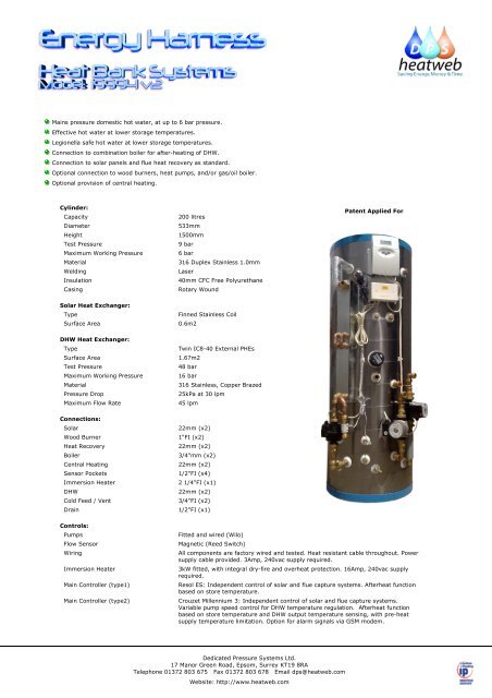
Patent Applied For<br />
Solar Heat Exchanger:<br />
Type<br />
Finned Stainless Coil<br />
Surface Area 0.6m2<br />
DHW Heat Exchanger:<br />
Type<br />
Twin IC8-40 External PHEs<br />
Surface Area 1.67m2<br />
Test Pressure<br />
48 bar<br />
Maximum Working Pressure<br />
16 bar<br />
Material<br />
316 Stainless, Copper Brazed<br />
Pressure Drop<br />
25kPa at 30 lpm<br />
Maximum Flow Rate<br />
45 lpm<br />
Connections:<br />
Solar<br />
Wood Burner<br />
Heat Recovery<br />
Boiler<br />
Central Heating<br />
Sensor Pockets<br />
Immersion Heater<br />
DHW<br />
Cold Feed / Vent<br />
Drain<br />
22mm (x2)<br />
1"FI (x2)<br />
22mm (x2)<br />
3/4"mm (x2)<br />
22mm (x2)<br />
1/2"FI (x4)<br />
2 1/4"FI (x1)<br />
22mm (x2)<br />
3/4"FI (x2)<br />
1/2"FI (x1)<br />
Controls:<br />
Pumps Fitted and wired (Wilo)<br />
Flow Sensor Magnetic (Reed Switch)<br />
Wiring<br />
Immersion Heater<br />
Main Controller (type1)<br />
Main Controller (type2)<br />
All components are factory wired and tested. Heat resistant cable throughout. Power<br />
supply cable provided. 3Amp, 240vac supply required.<br />
3kW fitted, with integral dry-fire and overheat protection. 16Amp, 240vac supply<br />
required.<br />
Resol ES: Independent control of solar and flue capture systems. Afterheat function<br />
based on store temperature.<br />
Crouzet Millennium 3: Independent control of solar and flue capture systems.<br />
Variable pump speed control for DHW temperature regulation. Afterheat function<br />
based on store temperature and DHW output temperature sensing, with pre-heat<br />
supply temperature limitation. Option for alarm signals via GSM modem.<br />
Dedicated Pressure Systems Ltd.<br />
17 Manor Green Road, Epsom, Surrey KT19 8RA<br />
Telephone 01372 803 675 Fax 01372 803 678 Email dps@heatweb.com<br />
Website: http://www.heatweb.com
Wiring<br />
CXC-210-ABA-LAAS+22+22+22+15+15+PA22U+PA22U+22<br />
Flow<br />
Switch<br />
CXC-200-DUBLIN<br />
8<br />
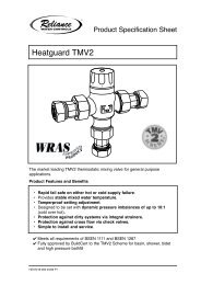
1 Plate Heat Exchanger, L18-14 (80kW)<br />
2 Flow switch<br />
3 Heat Exchanger Pump<br />
5 Drain off cock<br />
7 Coated steel casing<br />
8 Vent<br />
9 Cold Feed<br />
11 Wiring Centre<br />
12 Resol ES Controlller<br />
13 Boost Immersion Heater<br />
34 Sensor Pocket<br />
53 Y-Pattern Strainer<br />
55 Solid Fuel / Gravity 1'' Connection<br />
70 Spare Boss 1/2 FI BSP<br />
71 Spare Boss 3/4 FI BSP<br />
76 Flue Recovery Pump Assembly, 22mm<br />
77 Flow to Energy Catcher<br />
78 Return from Energy Catcher<br />
79 Solar Pump Assembly, 22mm<br />
80 Flow to Solar<br />
81 Return from Solar<br />
82 Sensors for Site Fitting<br />
90 Cold DHW In, 22mm<br />
92 Hot DHW Out<br />
92<br />
1<br />
55<br />
1<br />
55<br />
94<br />
7<br />
34<br />
82<br />
12<br />
11<br />
70<br />
13<br />
78<br />
71<br />
71<br />
81<br />
80<br />
79<br />
77<br />
76<br />
3<br />
2<br />
90<br />
34<br />
9<br />
34<br />
5<br />
53<br />
Connections onto the unit are compression or Tectite push-fit. When connecting into a push-fit fitting, ensure that a wheel-type pipe citter is<br />
used and that there are no burs that may damage the o-rings. A dicsonnecting tool is supplied to enable release of pipes from push-fit<br />
connections.<br />
The outlet from the thermostatic mixing valve is made using the supplied solder union and washer (cable tied to the pipework).Please ensure<br />
that the lowest point on the cold mains supply (after isolating valve) is fitted with a drain cock to both assist in servicing.<br />
Connections onto the unit are compression or Tectite push-fit. When connecting into a push-fit fitting, ensure that a wheel-type pipe citter is<br />
used and that there are no burs that may damage the o-rings. A dicsonnecting tool is supplied to enable release of pipes from push-fit<br />
connections.<br />
The outlet from the thermostatic mixing valve is made using the supplied solder union and washer (cable tied to the pipework).Please ensure<br />
that the lowest point on the cold mains supply (after isolating valve) is fitted with a drain cock to both assist in servicing.
ABOUT THE SYSTEM<br />
CXC-200-DUBLIN<br />
The Dublin Heat Bank has been designed to meet local authority requirements for a hot water system<br />
that is more efficient and cheaper to run than current installations.<br />
The aim of the design has been to maximise the efficiency of all thermal technologies that can be<br />
retro-fitted to properties, to reduce maintenance requirements, and to improve reliability by taking<br />
an existing combination boiler installation and adding facilities for flue heat recovery from the gas<br />
boiler, solar panels, a wood burner, and backup electric.<br />
The advantages of adding the technologies using the Dublin Heat Bank are as follows:<br />
1. Flue Heat Recovery systems can significantly improve the efficiency of a condensing boiler, and<br />
if connected to a suitably sized store will provide hot water during the heating season, using<br />
the recovered heat from the flue gases.<br />
2. Solar panels can connect directly to the Dublin Heat Bank to provide up to 50% of the<br />
households annual hot water requirements, with up to 100% of daily requirements on sunny<br />
days. The system uses a unique direct connection method along with drain-down protection<br />
that overcomes problems relating to freezing or overheat, and also removes the need for antifreeze<br />
and regular maintenance to maintain system pressure and anti-freeze content. The<br />
direct connection is also more efficient than using solar coils, and allows connection to very<br />
large solar arrays as well as individual panels.<br />
3. Wood burners can be connected directly to the Dublin Heat Bank using two connections<br />
provided as standard. This allows the wood burner to supplement both central heating and hot<br />
water, and can significantly reduce running costs and the carbon footprint of the property.<br />
Combined with a local supply of free wood, this method of heating can provide low cost hot<br />
water and heating during winter months,<br />
4. The pre-heat system that the Dublin Heat Bank employs uses stored energy to heat up water for<br />
domestic use. If the heated water is not quite hot enough for domestic use then it is fed through<br />
the combination boiler to be topped up to a suitable temperature. This method ensures that a<br />
minimum amount of gas is used, and the boiler is never used to heat stored water that may be<br />
left to go cold, or could otherwise have been heated using a free energy source.<br />
5. Electric backup to hot water is provided by an optionally fitted immersion heater in the Dublin<br />
Heat Bank. This adds an important backup feature that allows the user to run hot water on<br />
electricity if the boiler should fail to fire. It also allows the possibility of connecting a wind turbine<br />
or other low cost electrical source to further reduce running costs.<br />
6. Heat Pumps are another low temperature heat source that is often too low in temperature to<br />
provide adequate hot water. When used in conjunction with the Dublin Heat Bank, heat pumps<br />
can generate the majority of the stored energy using cheap rate overnight electricity, and this<br />
can then be topped up for use by the combination boiler.<br />
7. Legionella is a common problem in the supply of domestic hot water, and protecting against it<br />
is of key importance. The Dublin Heat Bank heats water instantaneously as it is used, and the<br />
stored water is not used to supply taps. No hot domestic water is stored and there is no chance<br />
of Legionella bacteria growing as can happen in stored hot water systems.<br />
8. Up to 9 bar cold supply pressures can be accommodated, with up to 6 bar pressure supplied to<br />
hot taps (boiler dependent), and all using a vented storage cylinder that can be fitted without<br />
unvented qualifications. In this way mains pressure systems can be installed using existing<br />
installer networks, even if they do not hold the additional qualifications for installing pressurised<br />
cylinders.<br />
9. Long term reliability is achieved by the use of a high grade stainless steel store combined with<br />
the thermal storage principle that prevents the store from attack by fresh ingress of water. All<br />
systems come with a 25 year guarantee on the store, and it is believed that the store should last<br />
considerably longer.
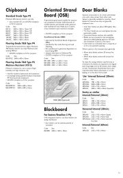
SCHEMATIC (Indirect Solar)<br />
CXC-200-DUBLIN<br />
The following schematic outlines a typical Dublin Heat Bank installation. All controls, pumps and valves<br />
are factory fitted to the Dublin Heat Bank, wired and tested, with 2 year guarantee on components<br />
and 1 year on-site backup.<br />
SOLAR<br />
PANEL<br />
SENSOR<br />
COLD STORAGE TANK<br />
Level Check<br />
F&E TANK<br />
DRAIN BACK TANK<br />
10 litre<br />
COLD<br />
FEED<br />
VENT<br />
SENSOR<br />
ENERGY<br />
CATCHER<br />
CENTRAL<br />
HEATING<br />
CIRCUIT<br />
COLD<br />
FEED<br />
BOILER<br />
Filling Point<br />
SENSOR<br />
PLATE<br />
HEAT<br />
EXCHANGER<br />
DIVERTING/MIXING VALVE<br />
HOT<br />
HEAT<br />
BANK<br />
+<br />
SOLAR<br />
CONTROLLER<br />
Must have relay output<br />
that can cativate drain<br />
down valve.<br />
-<br />
HWS<br />
BLENDING<br />
VALVE<br />
FLOW SWITCH<br />
SENSOR<br />
PUMP<br />
PUMP<br />
Drain Point
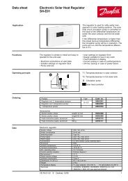
SCHEMATIC (Direct Sealed Solar)<br />
CXC-200-DUBLIN<br />
The following schematic outlines a typical Dublin Heat Bank installation. All controls, pumps and valves<br />
are factory fitted to the Dublin Heat Bank, wired and tested, with 2 year guarantee on components<br />
and 1 year on-site backup.<br />
SOLAR<br />
PANEL<br />
SENSOR<br />
Atmospheric Relief<br />
Valve<br />
Open<br />
COLD STORAGE TANK<br />
Filling and<br />
Level Check<br />
DRAIN BACK TANK<br />
20 litre<br />
SENSOR<br />
ENERGY<br />
CATCHER<br />
CENTRAL<br />
HEATING<br />
CIRCUIT<br />
COLD<br />
FEED<br />
BOILER<br />
Filling Point<br />
Auto Air Vent<br />
SENSOR<br />
PLATE<br />
HEAT<br />
EXCHANGER<br />
DIVERTING/MIXING VALVE<br />
HOT<br />
HEAT<br />
BANK<br />
+<br />
SOLAR<br />
CONTROLLER<br />
Must have relay output<br />
that can cativate drain<br />
down valve.<br />
-<br />
HWS<br />
BLENDING<br />
VALVE<br />
FLOW SWITCH<br />
SENSOR<br />
PUMP<br />
PUMP<br />
Drain Point
Wiring is based upon the<br />
RESOL DeltaSol ES Solar Controller,<br />
Set to Arrangement 19.<br />
The Heat Bank, and all connected equipment, must be installed by a competent person. Correct function and operation must be<br />
checked. It is important that the incoming mains power supply has sufficient current and voltage, taking into account the supply<br />
requirements of the rest of the property.<br />
All power supplies must be fitted with double pole isolation within the cylinder cupboard, as well as suitably rated MCB protection at<br />
distribution box.<br />
The controller compares the temperatures at the collector<br />
sensors S1 and S6 to the store temperature at store sensor S2.<br />
If one of the measured temperature differences is higher<br />
than the adjusted switch-on temperature differences, the<br />
corresponding pump (P1, P2) will be activated and the store<br />
will be loaded.<br />
Domestic hot water afterheating (P3) is possible via a<br />
thermostat function (S3).<br />
floating relay<br />
electromech.<br />
relay<br />
semi-conductor<br />
relay<br />
L'<br />
L N<br />
Sensors<br />
Bus<br />
GND<br />
S1<br />
S2<br />
S3<br />
S4<br />
S5<br />
S6<br />
S7<br />
S8<br />
V40<br />
CS10<br />
VBus<br />
RS232<br />
RP-A<br />
RP-M<br />
RP-R<br />
R5<br />
R4<br />
R3<br />
R2<br />
R1<br />
S1<br />
S6<br />
After Heating Diverting Valve<br />
P1<br />
(R1)<br />
P2<br />
(R2)<br />
S3<br />
S2<br />
Relay output<br />
Note<br />
R1<br />
solar pump (P1) with speed control<br />
R2<br />
pump (P2) with speed control<br />
RP-M<br />
domestic hot water afterheating<br />
RP-A<br />
Sensor input<br />
description<br />
S1<br />
temperature soar collector<br />
S2<br />
temperature store base<br />
S3<br />
S6<br />
CS10 (optional)<br />
temperature store top<br />
temperature flue recovery<br />
irradiation<br />
Heat<br />
Exchanger<br />
Pump<br />
Flow<br />
Switch<br />
Ensure earth continuity throughout. In wiring diagrams, earth and neutral wires may be abbreviated for clarity.
®<br />
DeltaSolES<br />
channel description factory<br />
setting<br />
COL1 temperature collector 1 -------<br />
TSTL temperature store base -------<br />
TSTU temperature store 1 top -------<br />
COL2 temperature collector 2 -------<br />
IRR irradiation -------<br />
n1 % speed relay 1 -------<br />
n2 % speed relay 2 -------<br />
h P1 operating hours relay 1 -------<br />
h P2 operating hours relay 2 -------<br />
h P3 operating hours relay 3 -------<br />
change<br />
to<br />
TIME time ------- Adjust the actual clock time.<br />
note<br />
Arr arrangement choice 1 19 Arrangement 19: 2 collector-system (east-/west<br />
collectors) with 1 store and domestic hot water<br />
afterheating<br />
DT O switch-on temperature difference 6.0 K Adjust the desired switch-on temperature<br />
differ ence. Note: This value applies to collector<br />
1 and 2<br />
DT F switch-off temperature difference 4.0 K Adjust the desired switch-off temperature<br />
differ ence. Note: This value applies to collector<br />
1 and 2<br />
DT S set temperature difference 10.0 K Adjust the desired set temperature difference.<br />
Note: This value applies to collector 1 and 2<br />
RIS rise 2 K If the adjusted temperature difference DTS is<br />
reached and if the temperature increases by<br />
the difference RIS, the speed will be increased<br />
by 10% respectively.<br />
Note: This value applies to collector 1 and 2<br />
S MX maximum store temperature 60 °C 90°C Adjust the desired maximum store temperature<br />
EM1 emergency temperature collector 1 140 °C Adjust this value to 200°C when the collector<br />
emergency shutdown function should not start.<br />
OCX1 option collector cooling collector 1 OFF<br />
OCN1 option minimum limitation collector<br />
OFF<br />
1<br />
OCF1 option frost protection collector 1 OFF<br />
EM2 emergency temperature collector 2 140 °C Adjust this value to 200°C when the collector<br />
emergency shutdown function should not start.<br />
OCX2 option collector cooling collector 2 OFF<br />
OCN2 option minimum limitation collector<br />
OFF<br />
2<br />
OCF2 option frost protection collector 2 OFF<br />
OREC option recooling OFF<br />
O TC option tube collector OFF<br />
NH O switch-on temperature thermostat 1 40.0 °C<br />
50°C<br />
Adjust the desired switch-on temperature for<br />
domestic hot water afterheating<br />
NH F switch-off temperature thermostat 1 45.0 °C Adjust the desired switch-off temperature for<br />
90°C<br />
domestic hot water afterheating<br />
08105 deltasol_es.sys.indd
CXC-200-DUBLIN<br />
Connections onto the unit are compression or Tectite push-fit. When connecting into a push-fit fitting, ensure that a wheel-type pipe cutter is<br />
used and that there are no burs that may damage the o-rings. A dicsonnecting tool is supplied to enable release of pipes from push-fit<br />
connections.<br />
Filling the Heat Bank:<br />
The unit is filled by the opening the supply to the Feed and Expansion tank, and any isolating valves on the feed from the FE tank. The FE tank<br />
will start to fill, followed by the store and any circuits directly connected to it. Always check that the water level in the FE tank is at least 3<br />
inches below the overflow, when the system is full.<br />
Wiring Diagram:<br />
It CXC-210-ABA-LAAS+22+22+22+15+15+PA22U+PA22U+22<br />
is advised to temporarily remove the ball from the ball valve in the FE tank to test the overflow operates under failure conditions. Always<br />
replace securely.<br />
Immersion Heater Overheat and Dry-Fire protection is provided within each heater by the use of an additional reset thermostat. If the<br />
heater power supplies are turned on before the unit is filled then there is a very good chance that the thermostat will need re-setting. Simply<br />
remove the immersion heater cap and push in the small black button on the thermostat - if it clicks it has reset.<br />
Testing of Hot Water Services:<br />
Once the store has fully heated up, it is important to check that hot water is available at all hot water outlets, and with the required flow<br />
rates and temperatures.<br />
The hot water supply temperature should be checked, and if required adjusted using the fitted thermostatic blending valve. Once set, the<br />
blending valve can be locked in position (see valve instruction sheet).<br />
If not locked in position, set the thermostatic mixing valve to maximum.<br />
Flow
CXC-200-DUBLIN