
You also want an ePaper? Increase the reach of your titles
YUMPU automatically turns print PDFs into web optimized ePapers that Google loves.
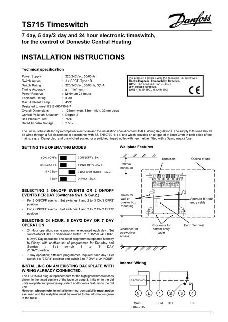
<strong>TS715</strong> Timeswitch<br />
7 day, 5 day/2 day and 24 hour electronic timeswitch,<br />
for the control of Domestic Central Heating<br />
<strong>INSTALL</strong>ATION INSTRUCTIONS<br />
Technical specification<br />
Power Supply<br />
: 220/240Vac, 50/60Hz<br />
Switch Action<br />
: 1 x SPST, Type 1B<br />
Switch Rating<br />
: 220/240Vac, 50/60Hz, 3(1)A<br />
Timing Accuracy<br />
: ± 1 min/month<br />
Power Reserve<br />
: Minimum 24 hours<br />
Enclosure Rating<br />
: IP30<br />
Max. Ambient Temp. : 45°C<br />
Designed to meet BS EN60730-2-7<br />
Overall Dimensions : 135mm wide, 88mm high, 32mm deep<br />
Control Pollution Situation : Degree 2<br />
Ball Pressure Test : 75°C<br />
Rated Impulse Voltage : 2.5Kv<br />
This product complies with the following EC Directives:<br />
Electro-Magnetic Compatibility Directive.<br />
(EMC) (89\336\EEC), (92\31\EEC)<br />
Low Voltage Directive.<br />
(LVD) (73\23\EEC), (93\68\EEC)<br />
The unit must be installed by a competent electrician and the installation should conform to IEE Wiring Regulations. The supply to this unit should<br />
be wired through a full disconnect in accordance with BS EN60730-1, i.e. one which provides an air gap of at least 3mm in both poles of the<br />
mains, e.g. a 13amp plug and unswitched socket, or a switched, fused outlet with neon; either fitted with a 3amp (max.) fuse.<br />
SETTING THE OPERATING MODES<br />
Wallplate Features<br />
3 ON/3 OFF's<br />
3 ON/3 OFF's<br />
5 + 2 Day<br />
2 ON/2OFF's -Sw.1.<br />
2 ON/2 OFF's - Sw.2.<br />
7 DAY or 24 HOUR - Sw.3.<br />
s<br />
30mm<br />
minimum<br />
▼<br />
Terminals<br />
Outline of unit<br />
7 Day<br />
24 Hour - Sw.4.<br />
SELECTING 3 ON/OFF EVENTS OR 2 ON/OFF<br />
EVENTS PER DAY (Switches Sw1. & Sw.2.)<br />
-For 3 ON/OFF events : Set switches 1 and 2 to '3 ON/3 OFFS'<br />
position.<br />
-For 2 ON/OFF events : Set switches 1 and 2 to '2 ON/2 OFFS'<br />
position.<br />
SELECTING 24 HOUR, 5 DAY/2 DAY OR 7 DAY<br />
OPERATION<br />
-24 Hour operation; same programme repeated each day : Set<br />
switch 4 to '24 HOUR' position and switch 3 to '7 DAY or 24 HOUR'.<br />
-5 Day/2 Day operation; one set of programmes repeated Monday<br />
to Friday, with another set of programmes for Saturday and<br />
Sunday : Set switch 3 to '5 DAY<br />
/2 DAY' position.<br />
-7 Day operation; different programmes required each day : Set<br />
switch 4 to '7 DAY' position and switch 3 to '7 DAY or 24 HOUR'.<br />
<strong>INSTALL</strong>ING ON AN EXISTING BACKPLATE WITH<br />
WIRING ALREADY CONNECTED.<br />
The <strong>TS715</strong> ia a plug-in replacements for the highlighted timeswitches<br />
shown in the tinted section of the table on page 3. It fits on to the old<br />
units wallplate and provide equivalent and/or extra features to the old<br />
unit.<br />
However, please note, terminal to terminal compatibility must not be<br />
assumed and the wallplate must be rewired to the information given<br />
in the table.<br />
Holes for<br />
wall or<br />
plaster box<br />
mounting<br />
▲<br />
Clearance for<br />
screwdriver<br />
access<br />
▼<br />
Internal Wiring<br />
ELECTRONICS<br />
Knockouts for<br />
bottom entry<br />
cable<br />
N L 1 2 3 4<br />
Earth Terminal<br />
MAINS COM OFF ON<br />
FUSED 3A<br />
Aperture for rear<br />
entry cable<br />
1
NEW <strong>INSTALL</strong>ATION<br />
1. Select the desired fixing position.<br />
2. When fixing the wallplate note that the terminals are at the top<br />
and the vertical centre line of the unit lies between terminals 4<br />
& 5.<br />
3. Fix the wallplate to the wall or plaster box as required.<br />
4. Surface cables can only enter from below the unit. If mounted<br />
on a plaster box, cables can enter from the rear through the<br />
aperture in the wallplate.<br />
5. If the unit is replacing an existing time control having an<br />
incompatible wallplate and wiring configuration, then the wiring<br />
conversions (see table) will be of assistance.<br />
6. The <strong>TS715</strong> does not require an earth connection.<br />
7. The diagrams below show typical wiring circuit's with which the<br />
units may be used. Terminal to terminal wiring information for<br />
complete control systems is supplied with the WB12 Wiring Box<br />
which is recommended for ease of<br />
installation.<br />
IMPORTANT: Please note that the switch contacts are voltage<br />
free. Should the timeswitch be controlling a mains voltage<br />
circuit,a wire link must be fitted between terminal1 and L of the<br />
wallplate.<br />
8. Clear all dust and debris from the area.<br />
9. Locate the slots in the top surface of the module over the lugs<br />
at the top of the wallplate, and hinge downwards until the<br />
module is pressed fully against the wallplate. Tighten the two<br />
screws from below to fix the module to the wallplate.<br />
10. Before setting the programmes the unit should be RESET by<br />
pressing the recessed button marked R/S. Ensure the mains<br />
power to the control circuit is switched on, and check the circuits<br />
as follows.<br />
11. Use the SELECT button to get to the ON mode to switch the<br />
output ON. Independently adjust the cylinder thermostat and<br />
room thermostat (if fitted), in turn, and check that the services<br />
operate correctly. Use the SELECT button to get to OFF mode<br />
and check that the services do not operate.<br />
12. The <strong>TS715</strong> is supplied with the following factory pre-set<br />
programme which will be active after a RESET has been<br />
performed. When in 24 hour mode the factory pre-set programme<br />
is equivalent to the Monday to Friday settings below operating<br />
every day.<br />
The factory pre-set programme can be changed as required. If<br />
the <strong>TS715</strong> is working in 7 Day mode then it is possible to<br />
programme different ON/OFF times every day. Refer to the<br />
User Instructions supplied with the unit.<br />
Days<br />
Monday<br />
to<br />
Friday<br />
Saturday<br />
&<br />
Sunday<br />
3 ON/3 OFF<br />
Mode<br />
1<br />
2<br />
3<br />
4<br />
5<br />
6<br />
1<br />
2<br />
3<br />
4<br />
5<br />
6<br />
2 ON/2 OFF<br />
Mode<br />
1<br />
2<br />
-<br />
-<br />
3<br />
4<br />
1<br />
2<br />
-<br />
-<br />
3<br />
4<br />
Programme<br />
ON<br />
OFF<br />
ON<br />
OFF<br />
ON<br />
OFF<br />
ON<br />
OFF<br />
ON<br />
OFF<br />
ON<br />
OFF<br />
Switching<br />
Times<br />
6:30 AM<br />
8:30 AM<br />
12:00 PM<br />
12:00 PM<br />
5:00 PM<br />
10:30 PM<br />
7:30 AM<br />
10:00 AM<br />
12:00 PM<br />
12:00 PM<br />
5:00 PM<br />
10:30 PM<br />
13 The units incorporate time and programme memory backup for<br />
up to two days. In the event of a mains power failure, the outputs<br />
will switch to OFF and a battery symbol will blink in the display.<br />
During the period up to the second midnight following the power<br />
failure, power resumption will result in the units taking control<br />
according to the User's programme. After the second midnight,<br />
the display will become blank, and the memory will be lost. After<br />
the power is restored the unit should be manually reset using the<br />
R/S button behind the flap. The clock will be at 12:00 PM MO with<br />
both outputs OFF, the factory pre-set programme will be active,<br />
and any User programme requirements will have to be reentered.<br />
TYPICAL CONTROL CIRCUITS The use of Danfoss Randall Control Packs with WB12 wiring centre is recommended. The WB12 includes<br />
terminal to terminal wiring details for HEATSHARE (HSP) and HEATPLAN (HPP) PACKS.<br />
Basic Gravity Hot Water-<br />
Pumped Heating System<br />
Controlled Gravity Hot Water -<br />
Pumped Heating System<br />
Fully Pumped System<br />
3 port Mid-position Valve<br />
HEAT<br />
SHARE<br />
MAINS LOAD NOT LOAD<br />
fused 3A COM OFF USED ON<br />
N L 1 2 3 4 <strong>TS715</strong><br />
MAINS LOAD NOT LOAD<br />
fused 3A COM OFF USED ON<br />
N L 1 2 3 4 <strong>TS715</strong><br />
MAINS LOAD NOT LOAD<br />
fused 3A COM OFF USED ON<br />
N L 1 2 3 4 <strong>TS715</strong><br />
N<br />
L<br />
LINK<br />
RMT<br />
N<br />
L<br />
LINK<br />
AT<br />
RMT<br />
N<br />
L<br />
LINK<br />
AT<br />
RMT<br />
HP28C<br />
HS3<br />
BOILER<br />
PUMP<br />
EARTHS NOT<br />
SHOWN.<br />
ENSURE<br />
EARTH<br />
CONTINUITY<br />
THROUGHOUT<br />
BOILER<br />
PUMP<br />
EARTHS NOT<br />
SHOWN.<br />
ENSURE<br />
EARTH<br />
CONTINUITY<br />
THROUGHOUT<br />
BOILER<br />
PUMP<br />
EARTHS NOT<br />
SHOWN.<br />
ENSURE<br />
EARTH<br />
CONTINUITY<br />
THROUGHOUT<br />
Typical Control of Pump<br />
for central heating on a solid fuel system<br />
Typical Control of Heating Only<br />
with boiler and pump<br />
Typical Control of Heating<br />
when used with combination boilers<br />
MAINS LOAD NOT LOAD<br />
fused 3A COM OFF USED ON<br />
N L 1 2 3 4 <strong>TS715</strong><br />
MAINS LOAD NOT LOAD<br />
fused 3A COM OFF USED ON<br />
N L 1 2 3 4 <strong>TS715</strong><br />
MAINS LOAD NOT LOAD<br />
fused 3A COM OFF USED ON<br />
N L 1 2 3 4 <strong>TS715</strong><br />
N<br />
L<br />
LINK<br />
RMT<br />
N<br />
L<br />
LINK<br />
RMT<br />
N<br />
L<br />
RMT<br />
PUMP<br />
EARTHS NOT<br />
SHOWN.<br />
ENSURE<br />
EARTH<br />
CONTINUITY<br />
THROUGHOUT<br />
BOILER<br />
PUMP<br />
EARTHS NOT<br />
SHOWN.<br />
ENSURE<br />
EARTH<br />
CONTINUITY<br />
THROUGHOUT<br />
BOILER<br />
TERMINALS<br />
N L OUTPUT INPUT<br />
EARTHS NOT<br />
SHOWN.<br />
ENSURE<br />
EARTH<br />
CONTINUITY<br />
THROUGHOUT<br />
2
PLUG-IN UPGRADE FOR EXISTING TIMESWITCHES.<br />
The <strong>TS715</strong> will directly replace the electro-mechanical and electronic timeswitches shown in the tinted section of the table, by plugging-in the<br />
new module to the old unit's wallplate. IT MUST NOT BE ASSUMED the existing wiring can be used. Refer to the chart below for the wiring<br />
conversions necessary.<br />
NOTE: <strong>TS715</strong> is a plug-in compatible with earlier TS15 & TS75 models.<br />
WIRING CONVERSIONS for other timeswitches which can be replaced with the Danfoss Randall <strong>TS715</strong>, refer to the second part of the<br />
table. If in any doubt, contact our Technical Services Department before proceeding with the replacement.-<br />
DANFOSS RANDALL<br />
<strong>TS715</strong><br />
MAINS LOAD An additional terminal block may be required<br />
where these disconnected leads (or pairs of<br />
leads) should be terminated<br />
E N L COM OFF SPARE ON<br />
E N L 1 2 3 4 A B C D<br />
THE EXISTING WALLPLATE MAY BE USED WHEN REPLACING THE FOLLOWING, BUT THE WIRING MUST BE RECONNECTED AS SHOWN BELOW.<br />
IN ADDITION, IN MAINS VOLTAGE SYSTEMS, FIT WIRE LINK BETWEEN L & COM TERMINALS OF WALLPLATE.<br />
ACL LS111,LS711,LP111 & LP711 E N L 1 2 4 3<br />
DRAYTON TEMPUS ONE &<br />
TEMPUS TWO<br />
E N L 1 3 4 2<br />
LANDIS & GYR RWB3 E N L - 3 1 4 2<br />
LANDIS & GYR RWB30 E N L 2 3 1 4<br />
THE TS75/TS15 WALLPLATE MUST BE USED TO REPLACE THE EXISTING WALLPLATE WHEN REPLACING THE FOLLOWING TIMESWITCHES. WIRING<br />
DETAILS ARE SHOWN BELOW. IN ADDITION, IN MAINS VOLTAGE SYSTEMS, FIT WIRE LINK BETWEEN TERMINAL 1 & L OF WALLPLATE.<br />
GRASSLIN 45, 45A, 45E E 2 1 3 - 4<br />
HONEYWELL ST6100 E N L 1 2 3 4 - -<br />
HORSTMANN 424 EMERALD &<br />
PEARL AUTO RANGE<br />
E N L1 3 - 2 4 5<br />
HORSTMANN 423 PEARL<br />
EMERALD & TOPAZ<br />
E N L 3 - 1 4 2 5 6<br />
HORSTMANN KMK2A YMK2 E 3 4 1 - 2<br />
HORSTMANN 425 CORONET E N L 5 6 1 4 2 3<br />
DANFOSS RANDALL 911 E N L 5 4 2 6<br />
DANFOSS RANDALL<br />
103, 103E, 103E5 & 103E7<br />
E 5 6 3 - 2 1<br />
RANDALL 3020 E 1,7 6 - - 2 4 3 5<br />
DANFOSS RANDALL SET 1 E N L 5 6 2 4<br />
RANDALL TSR2 E 3 2 1 - 4 5 6 7<br />
PEGLER SUNVIC SP20 & SP25/30 E N L 3 4 S 5<br />
POTTERTON MYSON EP4001 E N L 5 2 4 A B C D<br />
SANGAMO M6 E 4,5 6 3 2 7 1 8<br />
SANGAMO 410 FORM 8 E 4,5 3 - 2 6 1 7 8<br />
SANGAMO S254 FORM 2<br />
S408 FORM 5, S251 FORM 2<br />
E N L - - LOAD<br />
SANGAMO S610 FORM 2<br />
S611 FORM 2, S612 FORM 2<br />
S408 FORM 4, S408 FORM 6<br />
S253 FORM 2, S255 FORM 2<br />
E<br />
N<br />
MOTOR<br />
LIVE<br />
SWITCH<br />
LIVE<br />
- LOAD<br />
SANGAMO S409 FORM 8 E 3,N 5,L 6 - 1 2<br />
SANGAMO S263 FORM 2<br />
SANGAMO S264 FORM 2<br />
E N L - OFF ON<br />
SMITHS IND. MKI, MKII E N L P2 - P1 P3<br />
SMITHS IND. CENTROLLER 30 E 1 2 - - 3 4,5 6<br />
SMITHS IND. CENTROLLER 40 E 1 2 - - 3 4,5<br />
SWITCHMASTER 300 E N L 4 - 2 1 3<br />
TOWERCHRON TC E 2 1 4 - 3 7 8 9 10 11<br />
VENNER VENNERETTE MKIIA E N L LINE - LOAD<br />
VENNER VENNERETTE MKIVA E 2 3 4 - 1<br />
VENNER VENOTIME (WITH<br />
NEON INDICATING CIRCUIT ON)<br />
E N L - 1 2 3<br />
VENNER VENOTIME (WITH<br />
NEON INDICATING POWER ON)<br />
E N L 2 1 3<br />
VENNER VENNERON,<br />
VENNERON P<br />
E 3 2 1 - 4<br />
3
Danfoss Randall can accept no responsibility for possible errors in catalogues, brochures and other printed material, and reserves the right to alter its products without notice.<br />
This also applies to products already on order provided that such alterations can be made without subsequent changes being necessary in specifications already agreed.<br />
Danfoss Randall Ltd.,<br />
Ampthill Road,<br />
Bedford, MK42 9ER.<br />
Tel: 01234 364621 Fax: 01234 219705<br />
Email: danfossrandall@danfoss.com<br />
Website: www.danfoss-randall.co.uk<br />
4<br />
Part No: 8861 Iss 7 07/01