In System Programming (ISP) for ATMEL chips
In System Programming (ISP) for ATMEL chips
In System Programming (ISP) for ATMEL chips

You also want an ePaper? Increase the reach of your titles
YUMPU automatically turns print PDFs into web optimized ePapers that Google loves.
<strong>In</strong> <strong>System</strong> Programmer (<strong>ISP</strong>) <strong>for</strong> <strong>ATMEL</strong> micro controllers<br />
http://www.ikalogic.com/isp.php<br />
Page 1 of 29<br />
26-02-2008<br />
Home Projects Tutorials Schematics Pics&Clips Downloads Contact<br />
<strong>In</strong> <strong>System</strong> <strong>Programming</strong> (<strong>ISP</strong>) <strong>for</strong> <strong>ATMEL</strong> <strong>chips</strong><br />
A step by step construction guide<br />
By Ibrahim Kamal (ika@ikalogic.com)<br />
Last update: 12/2/08<br />
Supported devices:<br />
AT89S51, AT89S52, AT89S53, AT89S8253, AT89S2051, AT89S4051, AVR family<br />
(Tested on the AT89S52 and ATMEGA16L)<br />
Prgrammer software:<br />
A free programmer software can be downloaded at the end of this page<br />
Overview<br />
If you didn't guess it from the title, <strong>ISP</strong><br />
is a way to serially program your micro<br />
controller, while it resides in its place, in<br />
other words, without removing the chip<br />
from your board.<br />
Whether you're just starting in the <strong>ATMEL</strong> micro<br />
controllers, or you're familiar with it, <strong>ISP</strong> (<strong>In</strong><br />
<strong>System</strong> <strong>Programming</strong>) will provide you a simple<br />
and af<strong>for</strong>dable home made solution to program<br />
and debug your micro controller based project.<br />
Sometimes, <strong>ISP</strong> can become very useful, when<br />
adjusting some delays, frequencies or any other<br />
values that you would intend to find by trial and<br />
error.. a process that would otherwise take too<br />
much time.<br />
How does <strong>ISP</strong> works?<br />
Normally, the flash memory of an <strong>ATMEL</strong> micro controller is Pins used <strong>for</strong> <strong>ISP</strong><br />
programmed using a parallel interface, which consists of sending MOSI: data input<br />
the data byte by byte (using 8 independent lines <strong>for</strong> the data,<br />
MISO: data output<br />
and another bunch of lines <strong>for</strong> the address, the control word and<br />
SCK: clock input<br />
clock input). On the other hand <strong>ISP</strong> is per<strong>for</strong>med using only 4<br />
lines, and literally, data is transferred through 2 lines only, RESET: used to activate<br />
as in a I2C interface, where data is shifted in bit by bit though the serial <strong>Programming</strong><br />
MOSI line, with a clock cycle between each bit and the next (on the SCK line).<br />
MISO line is used <strong>for</strong> reading and <strong>for</strong> code verification, it is only used to output the code from<br />
the FLASH memory of the micro controller.<br />
The RST pin, which is normally used to reset the device, is also used to enable the 3 pins<br />
(MOSI, MISO and SCK) to be used <strong>for</strong> <strong>ISP</strong> simply by setting RST to HIGH (5V), otherwise if<br />
RST is low (0V), your program start running and those three pins, are used normally as P1.5,<br />
P1.6 and P1.7.<br />
Here is <strong>ISP</strong> <strong>Programming</strong> sequence as described in <strong>ATMEL</strong><br />
datasheets:
<strong>In</strong> <strong>System</strong> Programmer (<strong>ISP</strong>) <strong>for</strong> <strong>ATMEL</strong> micro controllers<br />
http://www.ikalogic.com/isp.php<br />
Page 2 of 29<br />
26-02-2008<br />
"The Code memory array can be programmed using the serial <strong>ISP</strong><br />
interface while RST is pulled to VCC. The serial interface consists<br />
of pins SCK, MOSI (input) and MISO (output). After RST is set<br />
high, the <strong>Programming</strong> Enable instruction needs to be executed<br />
first be<strong>for</strong>e other operations can be executed. Be<strong>for</strong>e a<br />
reprogramming sequence can occur, a Chip Erase operation is<br />
required.<br />
The Chip Erase operation turns the content of every memory<br />
location in the Code array into FFH.<br />
Either an external system clock can be supplied at pin XTAL1 or a<br />
crystal needs to be connected across pins XTAL1 and XTAL2. The<br />
maximum serial clock (SCK) frequency should be less than<br />
1/16 of the crystal frequency. With a 33 MHz oscillator clock, the<br />
maximum SCK frequency is 2 MHz. "<br />
Pins used <strong>for</strong> <strong>ISP</strong><br />
This is as deep as i got in the <strong>ISP</strong> process, as i am using a ready made software that will handle<br />
the transfer protocol. some more detailed in<strong>for</strong>mation about the <strong>ISP</strong> functioning can be found at<br />
www.8052.com and at www.avrfreaks.net. but this is all you need to know to build and<br />
use this extra simple programming device. Now that you know some theory about the <strong>ISP</strong>,<br />
you should be ready to build the hardware interface. As you will soon discover, it maybe the<br />
simplest circuit that will find in this web site!<br />
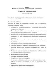
The Circuit:<br />
AVR <strong>In</strong>-<strong>System</strong> Programmer<br />
Four-port in-system programmer <strong>for</strong> Atmel<br />
AVR Microcontrollers<br />
ezTools USB to I2C<br />
Let you to do I2C debugging in Easy Way
<strong>In</strong> <strong>System</strong> Programmer (<strong>ISP</strong>) <strong>for</strong> <strong>ATMEL</strong> micro controllers<br />
http://www.ikalogic.com/isp.php<br />
Page 3 of 29<br />
26-02-2008<br />
This circuit is a modification from an original deign of Jerry Meng, and it is compatible with the<br />
software/cable proposed at www.aec-electronics.co.nz<br />
Important note:<br />
The schematic above indicates a 74LS08 IC, and I did build the programmer with a 74LS08 IC.<br />
However, using a 74HC08, or even better a 74HCT08 IC would be much safer, will give you a<br />
better per<strong>for</strong>mance and allow you to use a longer cable.<br />
The circuit almost talks <strong>for</strong> itself, the only part that may need some explanation, is the 4 AND<br />
gates. Connecting both 2 inputs of the AND gates as shown makes it act like a buffer, to<br />
protect the parallel port. (Shortly, a buffer is a device that will isolate 2 circuits)<br />
Then, the pins P1,P2,P3,P4 have to be connected respectively to P1.5, P1.6, P1.7 and RST in<br />
the micro controller.<br />
Finally, J1 is the connection to the computer parallel port.<br />
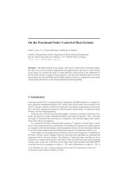
The PCB and the housing :<br />
I used an old parallel printer cable, and the whole circuit is mounted inside the the connector<br />
plastic box.<br />
A glance at this pictures may be enough to understand how the PCB<br />
is mounted and welded to the parallel port connector. To achieve this,<br />
some precision have to be taken in account when producing the PCB.
<strong>In</strong> <strong>System</strong> Programmer (<strong>ISP</strong>) <strong>for</strong> <strong>ATMEL</strong> micro controllers<br />
http://www.ikalogic.com/isp.php<br />
Page 4 of 29<br />
26-02-2008<br />
cause some damage the the buffer circuit.<br />
Note than PINs 14 to 25 of the parallel port are on the Components<br />
side of the board, and thus cannot be welded.. but luckily, from all<br />
those pins we only need the Ground (0V) (pins 18 to 25), which were<br />
all connected to the board, simply through a single jumper wire. (you<br />
can notice it, it's the orange wire in the shown picture at the left)<br />
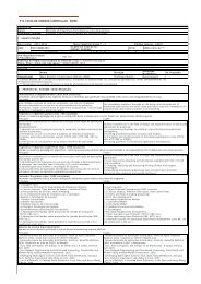
Below is another overall view of the device be<strong>for</strong>e being<br />
encasulated. Also notice in the Micro controller end of the cable, which<br />
is simple the female connector of standard pin header. I wont give<br />
more details about this part, i'll leave it to your imaginations! The<br />
important thing is to solder the cable to a secure connector instead of<br />
leaving the wires free to touch each others, which could<br />
here is a shot of the device<br />
in action. the picture may<br />
not be as clear as in reality,<br />
but i found the High<br />
Brightness LED to be cooler<br />
than what i've imagined..
<strong>In</strong> <strong>System</strong> Programmer (<strong>ISP</strong>) <strong>for</strong> <strong>ATMEL</strong> micro controllers<br />
http://www.ikalogic.com/isp.php<br />
Page 5 of 29<br />
26-02-2008<br />
Here is a shot of some<br />
other <strong>ISP</strong> programmers I<br />
made <strong>for</strong> some of my<br />
friends.<br />
www.qengine.com<br />
Feedback - Ads by Google<br />
Connecting the programmer to the Micro Controller<br />
Many visitors were confused on how to connect this programmer to the micro controller. Well, in<br />
general, <strong>ISP</strong> is made to program the Micro controller while it resides in its place, so all the<br />
standard connection <strong>for</strong> the micro controller to run properly are to be made.<br />
As Mr Sarma - a regular visitor, reviewer and a friend - suggested, here are some examples<br />
showing how to connect the programmer to different types of micro controllers:<br />
1- Connecting the programmer to an AT89S52
<strong>In</strong> <strong>System</strong> Programmer (<strong>ISP</strong>) <strong>for</strong> <strong>ATMEL</strong> micro controllers<br />
http://www.ikalogic.com/isp.php<br />
Page 6 of 29<br />
26-02-2008<br />
1- Connecting the programmer to an ATMEGA16L<br />
Note that with the ATMEGA AVR family, You don't need to add a crystal resonator, as those<br />
<strong>chips</strong> contains an internal resonator, making it ready to use simply by connecting the 5V and<br />
GND supply rails.
<strong>In</strong> <strong>System</strong> Programmer (<strong>ISP</strong>) <strong>for</strong> <strong>ATMEL</strong> micro controllers<br />
http://www.ikalogic.com/isp.php<br />
Page 7 of 29<br />
26-02-2008<br />
The programmer software<br />
This is the piece of software that will take the HEX file generated by whatever compiler you are<br />
using, and send it - with respect to the very specific <strong>ISP</strong> transfer protocol - to the micro<br />
controller.<br />
The software I am proposing was designed to be compatible with a multitude of <strong>ISP</strong><br />
programming cables. in most of cases, all the difference is the pins used on the parallel port to<br />
per<strong>for</strong>m the data transfer.<br />
The only thing you need to<br />
do is to go through 'Setup',<br />
and chose the 'AEC <strong>ISP</strong>'<br />
cable pinout. once chosen,<br />
you will notice that it<br />
matches the circuit on this<br />
page.<br />
If you have more than one<br />
parallel port (never seen<br />
this a lot..) chose the one<br />
to which the programmer<br />
is connected.<br />
The link to download the<br />
software is at the end of
<strong>In</strong> <strong>System</strong> Programmer (<strong>ISP</strong>) <strong>for</strong> <strong>ATMEL</strong> micro controllers<br />
http://www.ikalogic.com/isp.php<br />
Page 8 of 29<br />
26-02-2008<br />
this article.<br />
Setting up the software to be used with the programmer hardware<br />
If it doesn't work...:<br />
Now if your programmer doesn't work, don't panic and check the following:<br />
1- Make sure the cable is no longer than 50 cm (though i made it work with a 1meter cable..)<br />
long cables tend to increase noise interference especially with TTL devices.<br />
2- Try more than one device, I had two<br />
AT89S52 which which had their <strong>ISP</strong> port<br />
damaged somehow, as they could be<br />
programmed through the parallel programmer<br />
and functioned correctly, but wouldn't let me<br />
to program them through <strong>ISP</strong><br />
3- If you can read a hex file, which was<br />
written by any other programmer , but you<br />
CANNOT Write another HEX file using the <strong>ISP</strong><br />
programmer, this is - without a doubt -<br />
caused by a damaged chip.<br />
4- Contact me, if the solutions above didn't<br />
work.<br />
Join the Mailing List<br />
Let us get in touch with you when we<br />
upload new interesting content.<br />
Name:<br />
Email:<br />
nmlkji Subscribe nmlkj Unsubscribe GO<br />
Get your Free Mailing List<br />
by Bravenet.com<br />
Electronic Datasheets<br />
Datasheets on 500,000+ Part Numbers Free<br />
& Easy Component Search Tool!<br />
PIC & AVR C Compilers<br />
Compile, Simulate, Program! IDE's,<br />
Programmers & Development<br />
Download the zip file <strong>for</strong> this project<br />
includes the schematic and the printed circuit board in expressPCB <strong>for</strong>mat.<br />
[note: i use ExpressPCB(FREEWARE) to design the schematics and the PCB]<br />
Download <strong>ISP</strong>-PROG, the programmer software.<br />
The Discussion<br />
Let me and the visitors hear from you, share your questions and knowledge and propose<br />
other related articles and links. Feel free to correct any scientific mistake.<br />
Posted by:<br />
amol<br />
my isp working very good ,,,,,i use it <strong>for</strong> my project.....i m 4m india...........in pune thanks.....
<strong>In</strong> <strong>System</strong> Programmer (<strong>ISP</strong>) <strong>for</strong> <strong>ATMEL</strong> micro controllers<br />
http://www.ikalogic.com/isp.php<br />
Page 9 of 29<br />
26-02-2008<br />
on: 07 Apr 2007<br />
Posted by:<br />
ikalogic<br />
on: 07 Apr 2007<br />
It's nice to hear that amol! keep the good work!thx <strong>for</strong> your comment.<br />
Reply With Quote<br />
Reply With Quote<br />
Posted by:<br />
jun_China<br />
on: 08 Apr 2007<br />
Posted by:<br />
ikalogic<br />
on: 08 Apr 2007<br />
Posted by:<br />
Chris Keays<br />
on: 11 Apr 2007<br />
Posted by:<br />
chris Keays<br />
on: 11 Apr 2007<br />
Posted by:<br />
ikalogic<br />
on: 11 Apr 2007<br />
Posted by:<br />
Jawad Lateef<br />
on: 11 Apr 2007<br />
Posted by:<br />
ikalogic<br />
on: 11 Apr 2007<br />
I would like to try again,because i have tried several times,but failure,i hope I will be<br />
successful.thank you!<br />
Reply With Quote<br />
[Quoting: jun_China] I would like to try again,because i have tried several times,but<br />
failure,i hope I will be successful.thank you!<br />
well yes, try again, and again.. beleive me, it's worth the hard work! may it not work this<br />
time, leave a message here with your observations, and i'll help you to get it working.<br />
Reply With Quote<br />
Do yourself a favor and get the real software on the atmel site.This program works sometimes<br />
and sometimes it is very troublesome!This code is just another type like asim Khan's program.<br />
It should not matter how long the cable is as long as it is shielded (no longer than 3 ft, mind<br />
you)Using the parallel port like this is very troublesome. Because all PC's are different, and all<br />
parallel ports are different, it can work perfectly <strong>for</strong> one person and NEVER work <strong>for</strong> the next<br />
guy.I could read the signature bytes every single time, but never program the device. I have<br />
more than one 89S51 and they are NOT damaged! It is the poorly written software. Good Luck<br />
Reply With Quote<br />
[Quoting: Chris Keays] Do yourself a favor and get the real software on the atmel site.This<br />
program works sometimes and sometimes it is very troublesome!This code is just another<br />
type like asim Khan's program. It should not matter how long the cable is as long as it is<br />
shielded (no longer than 3 ft, mind you)Using the parallel port like this is very troublesome.<br />
Because all PC's are different, and all parallel ports are different, it can work perfectly <strong>for</strong><br />
one person and NEVER work <strong>for</strong> the next guy.I could read the signature bytes every single<br />
time, but never program the device. I have more than one 89S51 and they are NOT<br />
damaged! It is the poorly written software. Good Luck<br />
I <strong>for</strong>got to add, with my current setup (nothing changed) I used the <strong>ISP</strong> software I<br />
downloaded on the atmel site and it worked perfectly, same cable, same programmer, same<br />
PC! So what does that tell you??<br />
Well, that tells me i've got to try <strong>ATMEL</strong>'s software...<br />
Reply With Quote<br />
[Quoting: chris Keays] I <strong>for</strong>got to add, with my current setup (nothing changed) I used the<br />
<strong>ISP</strong> software I downloaded on the atmel site and it worked perfectly, same cable, same<br />
programmer, same PC! So what does that tell you??<br />
Plzz tell me can i download program with this programmer and cable in 89C51.<br />
Reply With Quote<br />
Reply With Quote<br />
[Quoting: Jawad Lateef] Plzz tell me can i download program with this programmer and<br />
cable in 89C51.<br />
No, this programmer is only compatible with <strong>ISP</strong> powered devices like the 89SXX. Note that<br />
you'r program will work on a 89S51 exactly as it will work on a 89C51.<br />
Reply With Quote<br />
Posted by:<br />
vinoth kumar<br />
on: 13 Apr 2007<br />
Posted by:<br />
waterloo<br />
on: 14 Apr 2007<br />
very nice<br />
I think it is good.<br />
Reply With Quote<br />
Reply With Quote<br />
Posted by:<br />
jun_China<br />
on: 14 Apr 2007<br />
[Quoting: ikalogic]<br />
[Quoting: jun_China] I would like to try again,because i have tried several times,but<br />
failure,i hope I will be successful.thank you!
<strong>In</strong> <strong>System</strong> Programmer (<strong>ISP</strong>) <strong>for</strong> <strong>ATMEL</strong> micro controllers<br />
http://www.ikalogic.com/isp.php<br />
Page 10 of 29<br />
26-02-2008<br />
well yes, try again, and again.. beleive me, it's worth the hard work! may it not work this<br />
time, leave a message here with your observations, and i'll help you to get it working.<br />
Thanks very much,I operated the circuit by your circuit diagram,then connected it to PC,and<br />
programed with a light flash program,I found the S51 was programed correctly,and worked<br />
well.my english is poor,^_^Thanks again.<br />
Reply With Quote<br />
Posted by:<br />
Charin.E<br />
on: 17 Apr 2007<br />
Posted by:<br />
Ibrahim Kamal<br />
on: 17 Apr 2007<br />
Posted by:<br />
igno<br />
on: 18 Apr 2007<br />
Posted by:<br />
Ibrahim Kamal<br />
on: 18 Apr 2007<br />
Posted by:<br />
kalpesh patel<br />
on: 11 May 2007<br />
Posted by:<br />
Ibrahim Kamal<br />
on: 11 May 2007<br />
Sawasdee Krub,I am a newer in MCU and <strong>ISP</strong> field from Thailand. I am applying your <strong>ISP</strong>programming<br />
software and schematic. But still can not write the code on 'AT89S8253(TQFP)'.<br />
I have simple questions as following.1.When pluged the Parellel Port to a computer and 5Vadaptor<br />
not yet supply, the indicator LED is lighted. Is it right?2.Can I supply voltage 'Vcc-5V'<br />
directly to the Reset pin-4 without a seriated Cap-1uF(Because of the <strong>In</strong>ternal Power-On Reset<br />
feature).3.My X’tal is 20MHz,Does this <strong>ISP</strong> Programmer control SCK-signal frequency properly<br />
according to the MAX-1/16-Crystal Frequency and there is dynamic baud-rate depending X’tal-<br />
Frequency come along with this?4.I press 'Restart' button and next 'Read Signature', when<br />
starting programming the MCU, <strong>for</strong> recognition,Is it right?(Would you please give me the brief<br />
procedure of manual?)5.The <strong>ISP</strong> programmer reported 'NOT KNOWN(FF,FF,FF)' when finished<br />
pressing 'Read Signature' Button ,and when change the new one of MCU and recheck wiring of<br />
the schematic, this problem is persisted.Thank you <strong>for</strong> your sharing and I will do this when I<br />
know these enough. It is the good thing.Sorry <strong>for</strong> not skill in English.Charin.E<br />
Yes this is abolutely normal, same thing happends to me...<br />
Reply With Quote<br />
[Quoting: Charin.E] 1.When pluged the Parellel Port to a computer and 5V-adaptor not yet<br />
supply, the indicator LED is lighted. Is it right?2<br />
[Quoting: Charin.E]Can I supply voltage 'Vcc-5V' directly to the Reset pin-4 without a<br />
seriated Cap-1uF(Because of the <strong>In</strong>ternal Power-On Reset feature).<br />
It's better to keep the Capacitor connected, specially with long cables. (i tried to remove the<br />
cap, and some of the programmers didn't work.<br />
[Quoting: Charin.E]3.My X’tal is 20MHz,Does this <strong>ISP</strong> Programmer control SCK-signal<br />
frequency properly according to the MAX-1/16-Crystal Frequency and there is dynamic<br />
baud-rate depending X’tal-Frequency come along with this?<br />
I usually puc the frequency to MAXIMUM and let the software hande it. but when working with<br />
long cables, lowering down the frequency can make it safer...<br />
[Quoting: Charin.E]4.I press 'Restart' button and next 'Read Signature', when starting<br />
programming the MCU, <strong>for</strong> recognition,Is it right?(Would you please give me the brief<br />
procedure of manual?)5.The <strong>ISP</strong> programmer reported 'NOT KNOWN(FF,FF,FF)' when<br />
finished pressing 'Read Signature' Button ,and when change the new one of MCU and<br />
recheck wiring of the schematic, this problem is persisted.Thank you <strong>for</strong> your sharing and I<br />
will do this when I know these enough. It is the good thing.<br />
Well, here again, what i usually do it to hit the "Erase and program all" button. that's all.<br />
[Quoting: Charin.E]Sorry <strong>for</strong> not skill in English.Charin.E<br />
Let us know how it went... good luck<br />
[Quoting: Ibrahim Kamal]<br />
Yes this is abolutely normal, same thing happends to me...<br />
How come you get your led bright without power?<br />
Reply With Quote<br />
[Quoting: Charin.E] 1.When pluged the Parellel Port to a computer and 5V-adaptor not<br />
yet supply, the indicator LED is lighted. Is it right?2<br />
[Quoting: igno]How come you get your led bright without power?<br />
Reply With Quote<br />
Because the parallel port of the computer can provide some power through it's I/O pins...<br />
some people even use that to power their circuits.. but i'ld say it's not good engineering...<br />
Reply With Quote<br />
I am able to read hex file from 89s52 chip but can't erase or write the chip, even though i<br />
have tried it on three device but still i can't gate success. so, please help me.<br />
Reply With Quote<br />
[Quoting: kalpesh patel] I am able to read hex file from 89s52 chip but can't erase or write<br />
the chip, even though i have tried it on three device but still i can't gate success. so, please
<strong>In</strong> <strong>System</strong> Programmer (<strong>ISP</strong>) <strong>for</strong> <strong>ATMEL</strong> micro controllers<br />
http://www.ikalogic.com/isp.php<br />
Page 11 of 29<br />
26-02-2008<br />
help me.<br />
Try the following: 1-Put a 10uF capacitor between pin 9 of the uController and the 5V rail.2-<br />
Slow down the speed3-make sure PIN 31 (ea) of the uController is connected to 5VThis is<br />
mostly the type of problems I found with friends that couldn't get their <strong>ISP</strong> programmer<br />
working... hope this helps..<br />
Reply With Quote<br />
Posted by:<br />
Anonymous<br />
visitor<br />
on: 11 May 2007<br />
Posted by:<br />
Ibrahim Kamal<br />
on: 11 May 2007<br />
Posted by:<br />
kalpesh patel<br />
on: 11 May 2007<br />
Posted by:<br />
Ibrahim Kamal<br />
on: 11 May 2007<br />
[Quoting: Ibrahim Kamal]<br />
[Quoting: kalpesh patel] I am able to read hex file from 89s52 chip but can't erase or<br />
write the chip, even though i have tried it on three device but still i can't gate success. so,<br />
please help me.<br />
Try the following: 1-Put a 10uF capacitor between pin 9 of the uController and the 5V rail.2-<br />
Slow down the speed3-make sure PIN 31 (ea) of the uController is connected to 5VThis is<br />
mostly the type of problems I found with friends that couldn't get their <strong>ISP</strong> programmer<br />
working... hope this helps..<br />
I am using 10M Hz crystal. so, what amount of maximum speed i can use.<br />
[Quoting: ]<br />
[Quoting: Ibrahim Kamal]<br />
I am using 10M Hz crystal. so, what amount of maximum speed i can use.<br />
Reply With Quote<br />
[Quoting: kalpesh patel] I am able to read hex file from 89s52 chip but can't erase or<br />
write the chip, even though i have tried it on three device but still i can't gate success.<br />
so, please help me.<br />
Try the following: 1-Put a 10uF capacitor between pin 9 of the uController and the 5V<br />
rail.2-Slow down the speed3-make sure PIN 31 (ea) of the uController is connected to<br />
5VThis is mostly the type of problems I found with friends that couldn't get their <strong>ISP</strong><br />
programmer working... hope this helps..<br />
Well, i usually let the software handle this by chooseing "Maximum speed".. but you can get it<br />
by trial and error.. it depends on many things like cable length.. noize.. crystal (<strong>for</strong> sure)...<br />
etc.<br />
[Quoting: Ibrahim Kamal]<br />
Reply With Quote<br />
[Quoting: kalpesh patel] I am able to read hex file from 89s52 chip but can't erase or<br />
write the chip, even though i have tried it on three device but still i can't gate success. so,<br />
please help me.<br />
Try the following: 1-Put a 10uF capacitor between pin 9 of the uController and the 5V rail.2-<br />
Slow down the speed3-make sure PIN 31 (ea) of the uController is connected to 5VThis is<br />
mostly the type of problems I found with friends that couldn't get their <strong>ISP</strong> programmer<br />
working... hope this helps..<br />
Actually pin 31(ea) is generally used to select the rom and ram. i think which may came into<br />
picture after programming of the device. so, why sould we connect pin31 to Vcc at the time of<br />
programming using isp.<br />
[Quoting: kalpesh patel]<br />
[Quoting: Ibrahim Kamal]<br />
Reply With Quote<br />
[Quoting: kalpesh patel] I am able to read hex file from 89s52 chip but can't erase or<br />
write the chip, even though i have tried it on three device but still i can't gate success.<br />
so, please help me.<br />
Try the following: 1-Put a 10uF capacitor between pin 9 of the uController and the 5V<br />
rail.2-Slow down the speed3-make sure PIN 31 (ea) of the uController is connected to<br />
5VThis is mostly the type of problems I found with friends that couldn't get their <strong>ISP</strong><br />
programmer working... hope this helps..<br />
Actually pin 31(ea) is generally used to select the rom and ram. i think which may came<br />
into picture after programming of the device. so, why sould we connect pin31 to Vcc at the<br />
time of programming using isp.<br />
Let me correct this, Pin 31 (EA) Let the internal processor access external or internal memory.<br />
to use <strong>ISP</strong>, internal memory access must be enabled, in order to let the processor store the<br />
received serial data into the internal flash memory.<br />
Reply With Quote
<strong>In</strong> <strong>System</strong> Programmer (<strong>ISP</strong>) <strong>for</strong> <strong>ATMEL</strong> micro controllers<br />
http://www.ikalogic.com/isp.php<br />
Page 12 of 29<br />
26-02-2008<br />
Posted by:<br />
kalpesh patel<br />
on: 14 May 2007<br />
Posted by:<br />
Ibrahim Kamal<br />
on: 14 May 2007<br />
Posted by:<br />
danny<br />
on: 22 May 2007<br />
Posted by:<br />
Ibrahim Kamal<br />
on: 23 May 2007<br />
Posted by:<br />
mvs sarma<br />
on: 24 May 2007<br />
Posted by:<br />
mvs sarma<br />
on: 24 May 2007<br />
[Quoting: Ibrahim Kamal]<br />
[Quoting: kalpesh patel]<br />
[Quoting: Ibrahim Kamal]<br />
[Quoting: kalpesh patel] I am able to read hex file from 89s52 chip but can't erase or<br />
write the chip, even though i have tried it on three device but still i can't gate<br />
success. so, please help me.<br />
Try the following: 1-Put a 10uF capacitor between pin 9 of the uController and the 5V<br />
rail.2-Slow down the speed3-make sure PIN 31 (ea) of the uController is connected to<br />
5VThis is mostly the type of problems I found with friends that couldn't get their <strong>ISP</strong><br />
programmer working... hope this helps..<br />
Actually pin 31(ea) is generally used to select the rom and ram. i think which may came<br />
into picture after programming of the device. so, why sould we connect pin31 to Vcc at<br />
the time of programming using isp.<br />
Let me correct this, Pin 31 (EA) Let the internal processor access external or internal<br />
memory. to use <strong>ISP</strong>, internal memory access must be enabled, in order to let the processor<br />
store the received serial data into the internal flash memory.<br />
I have done all the things that you have suggested but still i can't get any positive result.<br />
[Quoting: kalpesh patel]<br />
[Quoting: Ibrahim Kamal]<br />
[Quoting: kalpesh patel]<br />
[Quoting: Ibrahim Kamal]<br />
Reply With Quote<br />
[Quoting: kalpesh patel] I am able to read hex file from 89s52 chip but can't erase<br />
or write the chip, even though i have tried it on three device but still i can't gate<br />
success. so, please help me.<br />
Try the following: 1-Put a 10uF capacitor between pin 9 of the uController and the 5V<br />
rail.2-Slow down the speed3-make sure PIN 31 (ea) of the uController is connected<br />
to 5VThis is mostly the type of problems I found with friends that couldn't get their<br />
<strong>ISP</strong> programmer working... hope this helps..<br />
Actually pin 31(ea) is generally used to select the rom and ram. i think which may<br />
came into picture after programming of the device. so, why sould we connect pin31 to<br />
Vcc at the time of programming using isp.<br />
Let me correct this, Pin 31 (EA) Let the internal processor access external or internal<br />
memory. to use <strong>ISP</strong>, internal memory access must be enabled, in order to let the<br />
processor store the received serial data into the internal flash memory.<br />
I have done all the things that you have suggested but still i can't get any positive result.<br />
The only couple of things that come through my head would be either a damaged or<br />
misconfigured parallel port.. did you try it on another pc?<br />
Reply With Quote<br />
erase..okproblem:write error at adress 00000000 byte written:02 byte read: 00help me<br />
please<br />
Reply With Quote<br />
[Quoting: danny] erase..okproblem:write error at adress 00000000 byte written:02 byte<br />
read: 00help me please<br />
Did you try all the tips i've posted in this <strong>for</strong>um?Did you try another chip?Is pin 31 of your<br />
atmel chip connected to Vcc?try all the tips in this <strong>for</strong>um, step by step, you should find what's<br />
wrong with your connections, and it should work.<br />
Reply With Quote<br />
Rge kapilesh patels comments- i would like him to check whether he modified programming<br />
frequency at left of SETUP button, to a value less than 1/16th of the crystal frequency used by<br />
him.i assemble apiece oncemore y-day and it is working fine- taking a calculated risk i didn't<br />
even use the AND gates suugested by IKA-- i use 15MHz crystal and i set the prog frequency<br />
to 455 Hz or even 200Hz.i hope kapilesh will come<strong>for</strong>ward with his commentsSarma<br />
Reply With Quote<br />
Sorry I spelled worngly It is Kalpesh PatelAlso,i suggest Kalpesh to check the PSU <strong>for</strong> clean<br />
and correct 5V supply. Sarma<br />
Reply With Quote
<strong>In</strong> <strong>System</strong> Programmer (<strong>ISP</strong>) <strong>for</strong> <strong>ATMEL</strong> micro controllers<br />
http://www.ikalogic.com/isp.php<br />
Page 13 of 29<br />
26-02-2008<br />
Posted by:<br />
Ibrahim Kamal<br />
on: 24 May 2007<br />
[Quoting: mvs sarma] Sorry I spelled worngly It is Kalpesh PatelAlso,i suggest Kalpesh to<br />
check the PSU <strong>for</strong> clean and correct 5V supply. Sarma<br />
hello Mr sarma.. thanks <strong>for</strong> sharing :)<br />
Reply With Quote<br />
Posted by:<br />
hadi<br />
on: 27 May 2007<br />
Posted by:<br />
Kishor Soni<br />
on: 01 Jun 2007<br />
is the best<br />
Dear sir,Is your <strong>ISP</strong> Programmer works with windows XP<br />
Reply With Quote<br />
Reply With Quote<br />
Posted by:<br />
Ibrahim Kamal<br />
on: 01 Jun 2007<br />
Posted by:<br />
Abhax<br />
on: 01 Jun 2007<br />
Posted by:<br />
Ibrahim Kamal<br />
on: 01 Jun 2007<br />
Posted by:<br />
suetaM<br />
on: 01 Jun 2007<br />
Posted by:<br />
Ibrahim Kamal<br />
on: 02 Jun 2007<br />
[Quoting: Kishor Soni] Dear sir,Is your <strong>ISP</strong> Programmer works with windows XP<br />
Yes it does work on winXP.<br />
Reply With Quote<br />
You have given the design specification <strong>for</strong> the cable .... but while setting up the main board<br />
wat are the small things to take care of....you mentioned 1)10 microf fromm rst pin to +vcc 2)<br />
Ea bar is at +vcc anything else.... Also can i use a 74541 IC instead of a and gate..... further<br />
more my parllel port can only output a max voltage of 3.22V as a logic high from the data<br />
pins. does the logic high neccessarily have to be above 4.5 volts????<br />
Yes, this should be enough...<br />
Yes sure, it's even better!<br />
No you dont!, 3.5V is enough, That's because we use a buffer.<br />
Reply With Quote<br />
[Quoting: Abhax] You have given the design specification <strong>for</strong> the cable .... but while setting<br />
up the main board wat are the small things to take care of....you mentioned 1)10 microf<br />
fromm rst pin to +vcc 2) Ea bar is at +vcc anything else....<br />
[Quoting: Abhax]Also can i use a 74541 IC instead of a and gate.....<br />
[Quoting: Abhax]further more my parllel port can only output a max voltage of 3.22V as a<br />
logic high from the data pins. does the logic high neccessarily have to be above 4.5<br />
volts????<br />
Reply With Quote<br />
Hello,I mounted the cable and I'm its ok to read the device.I understand that to read it I need<br />
both MOSI, MISO, CLK and RESET signals, cause one is the way of solicitations to 89s51 and<br />
other is the way of listening answers.I know both signals are operating ok, cause your<br />
software read only FF bytes when one of each cables are not plugged on my protoboard. And<br />
when are pluged, I read "real" values.So, all the four signals are operating ok to read, but<br />
when I try to write I have the "Write Error at adrress 0 ....." error.I tried to put the capacitor<br />
10uF to the source and the error continues.I tried with four microcontroler, all showed the<br />
same error.So, some idea?I unbelieve the problem is at 89s51 cause it's understanding my<br />
solicitations and answering.Other question... where do I found 89s51 <strong>ATMEL</strong> <strong>ISP</strong> programmer?<br />
Thanks,suetaM<br />
Reply With Quote<br />
[Quoting: suetaM] Hello,I mounted the cable and I'm its ok to read the device.I understand<br />
that to read it I need both MOSI, MISO, CLK and RESET signals, cause one is the way of<br />
solicitations to 89s51 and other is the way of listening answers.I know both signals are<br />
operating ok, cause your software read only FF bytes when one of each cables are not<br />
plugged on my protoboard. And when are pluged, I read "real" values.So, all the four<br />
signals are operating ok to read, but when I try to write I have the "Write Error at adrress<br />
0 ....." error.I tried to put the capacitor 10uF to the source and the error continues.I tried<br />
with four microcontroler, all showed the same error.So, some idea?I unbelieve the problem<br />
is at 89s51 cause it's understanding my solicitations and answering.Other question... where<br />
do I found 89s51 <strong>ATMEL</strong> <strong>ISP</strong> programmer?Thanks,suetaM<br />
well, let's start from the begining, did you connect pin 31 to 5V, and a crystal oscillator on 18<br />
and 19?try slowing down the process from the <strong>ISP</strong>prog software..what is the length of the<br />
cable?Try another power supply, if the power supply is not clean and too noizy it gives me the<br />
same symptomes. try operating from a battery and a 7805 regulator...let us know how it<br />
went.. good luck<br />
Reply With Quote<br />
Posted by:
<strong>In</strong> <strong>System</strong> Programmer (<strong>ISP</strong>) <strong>for</strong> <strong>ATMEL</strong> micro controllers<br />
http://www.ikalogic.com/isp.php<br />
Page 14 of 29<br />
26-02-2008<br />
Anonymous<br />
visitor<br />
on: 02 Jun 2007<br />
Posted by:<br />
Ibrahim Kamal<br />
on: 02 Jun 2007<br />
Posted by:<br />
Abhay<br />
on: 05 Jun 2007<br />
Posted by:<br />
Ibrahim Kamal<br />
on: 05 Jun 2007<br />
[Quoting: Ibrahim Kamal]<br />
[Quoting: suetaM] Hello,I mounted the cable and I'm its ok to read the device.I<br />
understand that to read it I need both MOSI, MISO, CLK and RESET signals, cause one is<br />
the way of solicitations to 89s51 and other is the way of listening answers.I know both<br />
signals are operating ok, cause your software read only FF bytes when one of each cables<br />
are not plugged on my protoboard. And when are pluged, I read "real" values.So, all the<br />
four signals are operating ok to read, but when I try to write I have the "Write Error at<br />
adrress 0 ....." error.I tried to put the capacitor 10uF to the source and the error<br />
continues.I tried with four microcontroler, all showed the same error.So, some idea?I<br />
unbelieve the problem is at 89s51 cause it's understanding my solicitations and<br />
answering.Other question... where do I found 89s51 <strong>ATMEL</strong> <strong>ISP</strong> programmer?<br />
Thanks,suetaM<br />
well, let's start from the begining, did you connect pin 31 to 5V, and a crystal oscillator on<br />
18 and 19?try slowing down the process from the <strong>ISP</strong>prog software..what is the length of<br />
the cable?Try another power supply, if the power supply is not clean and too noizy it gives<br />
me the same symptomes. try operating from a battery and a 7805 regulator...let us know<br />
how it went.. good luck<br />
I download other software and, whith the same cable schematic shown on this page I solve<br />
the problem. So, I can say the problem is the software.The software I downloaded can be find<br />
at http://www.aec-electronics.co.nz/index.php?page_id=18I tried to take out the 7408 buffer<br />
and it operate. So I changed my source to a computer source (5.15V) and it didn't operate.So,<br />
I installed a 10K resistor betwen the RESET and ground and a 0.1 uF capacitor betwen source<br />
and RESET, and it operate.So, my schematic folows (without 7408 or any buffer):DB25<br />
89S516 RESET7 MOSI8 CLK10 MISO18-25 GROUNDI suggest a cable with one more wire (6 at<br />
total), where you will plug on microcontroler Vcc (Source). Lets call it signal by<br />
MIC_SOURCE.So, to finish your cable, install a capacitor 0.1uF betwen MIC_SOURCE wire and<br />
RESET wire and a resistor betwen wire RESET and GROUND and download software<br />
athttp://www.aec-electronics.co.nz/index.php?page_id=18Its possible to run with it's page<br />
software, but on my micro it didn't happened.So, is it andDá-lhe Grêmio!!!!!!! (Soccer World<br />
Championship 1983 and 2 times America Championship)<br />
Reply With Quote<br />
[Quoting: suetaM ] I download other software and, whith the same cable schematic shown<br />
on this page I solve the problem. So, I can say the problem is the software.The software I<br />
downloaded can be find at http://www.aec-electronics.co.nz/index.php?page_id=18I tried<br />
to take out the 7408 buffer and it operate. So I changed my source to a computer source<br />
(5.15V) and it didn't operate.So, I installed a 10K resistor betwen the RESET and ground<br />
and a 0.1 uF capacitor betwen source and RESET, and it operate.So, my schematic folows<br />
(without 7408 or any buffer):DB25 89S516 RESET7 MOSI8 CLK10 MISO18-25 GROUNDI<br />
suggest a cable with one more wire (6 at total), where you will plug on microcontroler Vcc<br />
(Source). Lets call it signal by MIC_SOURCE.So, to finish your cable, install a capacitor<br />
0.1uF betwen MIC_SOURCE wire and RESET wire and a resistor betwen wire RESET and<br />
GROUND and download software athttp://www.aec-electronics.co.nz/index.php?<br />
page_id=18Its possible to run with it's page software, but on my micro it didn't<br />
happened.So, is it andDá-lhe Grêmio!!!!!!! (Soccer World Championship 1983 and 2 times<br />
America Championship)<br />
Wow! suetaM I am impressed, nice problem solving approach!And thanks a lot <strong>for</strong> sharing<br />
such useful in<strong>for</strong>mation to the visitors.See you soon!<br />
Reply With Quote<br />
Ya ok good news ..... my programmer works...... hey one thing the program you have written<br />
is perfect no problems.... but few things must be noted..... the Atmel datasheet mentions the<br />
use of two 33 microf capacitors with the crystal oscillator.... you kno that had spoilt my entire<br />
programmer..... i screwed 3 <strong>chips</strong> using that capacitors...... i had used 2 33microfarad<br />
electrolytic capacitors with the crystal connected to ground.... incase any of you have used it<br />
take it out and then try else try out a ceramic 33 microfarad..... i dont kno whether using a<br />
ceramic capacitor will work or not but it is definitely worth a try...... one more thing i wanted<br />
to ask is the programming is done and the program read the microcontroller flash too and<br />
programs it but it doesnt seem to run the way it is intended..... apart from grounding reset<br />
and connectine ea(pin 31) to Vcc wat else should be done ..... i had written a stepper motor<br />
program where the the pins 1.2 and 1.3 keep going on and off with 1 second period but the<br />
pins in the microcontroller remains at 5.15 volts. no change i dont understand why .... i am<br />
guessing the chip is screwed.....<br />
I didn't write this software, All the credit goes to Adam Dybkowski<br />
Reply With Quote<br />
[Quoting: Abhay] hey one thing the program you have written is perfect no problems....<br />
[Quoting: Abhay]but few things must be noted..... the Atmel datasheet mentions the use of<br />
two 33 microf capacitors with the crystal oscillator.... you kno that had spoilt my entire<br />
programmer..... i screwed 3 <strong>chips</strong> using that capacitors...... i had used 2 33microfarad<br />
electrolytic capacitors with the crystal connected to ground....
<strong>In</strong> <strong>System</strong> Programmer (<strong>ISP</strong>) <strong>for</strong> <strong>ATMEL</strong> micro controllers<br />
http://www.ikalogic.com/isp.php<br />
Page 15 of 29<br />
26-02-2008<br />
It's the first time i hear of some one using Electrolytic capacitors <strong>for</strong> a crystal oscillator, it's<br />
definately a bad thing to do!<br />
[Quoting: Abhay]incase any of you have used it take it out and then try else try out a<br />
ceramic 33 microfarad..... i dont kno whether using a ceramic capacitor will work or not but<br />
it is definitely worth a try......<br />
Thanks <strong>for</strong> the advice. i'll add that in case you don't have the right cerramic capacitor, you can<br />
not add any capacitor, and it'll work anyway, the frequency wont be very stable, but that's all.<br />
[Quoting: Abhay]one more thing i wanted to ask is the programming is done and the<br />
program read the microcontroller flash too and programs it but it doesnt seem to run the<br />
way it is intended..... apart from grounding reset and connectine ea(pin 31) to Vcc wat else<br />
should be done ..... i had written a stepper motor program where the the pins 1.2 and 1.3<br />
keep going on and off with 1 second period but the pins in the microcontroller remains at<br />
5.15 volts. no change i dont understand why .... i am guessing the chip is screwed.....<br />
why would you ground the RST pin? don't do that! just connect a resistor between it and the<br />
ground, and a 10uF electrolytic CAP between it and Vcc.If the programmer said "ready" then<br />
the code it downloaded on your chip sucessfully, so search <strong>for</strong> the error in the code or in your<br />
hardware.<br />
Reply With Quote<br />
Posted by:<br />
arun kumar<br />
on: 07 Jun 2007<br />
Posted by:<br />
Ibrahim Kamal<br />
on: 07 Jun 2007<br />
Posted by:<br />
mvs sarma<br />
on: 08 Jun 2007<br />
Posted by:<br />
Anonymous<br />
visitor<br />
on: 08 Jun 2007<br />
Posted by:<br />
suetaM<br />
on: 11 Jun 2007<br />
Posted by:<br />
mvs sarma<br />
on: 12 Jun 2007<br />
we r using at89c55 i want to load the program using parallel port programmer kit.where it is<br />
available in chennai<br />
Reply With Quote<br />
[Quoting: arun kumar] we r using at89c55 i want to load the program using parallel port<br />
programmer kit.where it is available in chennai<br />
Among all 8051 programmers, only the "s" series can be programmed via the <strong>ISP</strong> port. the<br />
AT89C55 cannot be programmed with the <strong>ISP</strong> programmer proposed on this page.<br />
Reply With Quote<br />
[Quoting: arun kumar] we r using at89c55 i want to load the program using parallel port<br />
programmer kit.where it is available in chennai<br />
Hi Arun, Unless you are particular about using 89c55 only, it will workout cheaper to shift to<br />
89S52 as these are very cheap at less than <strong>In</strong>dian Rs.40/- and this simple programmer can do<br />
<strong>for</strong> you and your job is done. Hope you will appreciate the economics of the idea.Sarma<br />
Reply With Quote<br />
[Quoting: Abhay] Ya ok ...... the Atmel datasheet mentions the use of two 33 microf<br />
capacitors with the crystal oscillator.... try...... o<br />
Hi Abhay, please look at the same datasheet carefully- you will notice that the CAPs are 33pF<br />
each (Pico farad-- and NOT Microfarad)thereis a musquito to elephant difference between pico<br />
to micro Hope this will help to serve you better.Sarma<br />
Reply With Quote<br />
Hello!I'm happy cause I solve the paralell <strong>ISP</strong> cable programming problem.But now I'm with a<br />
new problem.I implemented serial communication with 89s51 but when I turn off and turn on<br />
the 89s51 source it just don't operate more. I need to reprogram many times to it begin<br />
operate rightly.Someone with the same problem?<br />
Reply With Quote<br />
Hi suetaM,1. ensure that the 5V supply is noisefree. If you use 5V regulator -ensure that the<br />
input is more than 8Vdc even with a 20mA load at the output.2. ensure that the sck clock is<br />
set at LESS THAN 1/16th of the crystal frequency used.3. esuure that the cable length<br />
between RS232 port and the programmer is minimum.4. definitely check <strong>for</strong> any dry joints--<br />
DON'T USE TEMPORARY ESTABLISHMENT LIKE BREADBOARD as this will cause intermittant<br />
connections.5. put a 10uF capacitor between Vcc and Gnd VERY NEAR TO THE 89S52 PINS.6.<br />
ENSURE THAT PINS 40 AND 31 ARE CONNECTED PROPERLY. Perhaps you are already aware of<br />
all these funds.with these precautions you will succeed.Sarma<br />
Reply With Quote<br />
Posted by:<br />
maryam<br />
on: 21 Jun 2007<br />
hi dear all,does this programmer work with winxp?<br />
Reply With Quote<br />
Posted by:<br />
Ibrahim Kamal<br />
on: 21 Jun 2007<br />
[Quoting: maryam] hi dear all,does this programmer work with winxp?<br />
Yes, it does work <strong>for</strong> win XP
<strong>In</strong> <strong>System</strong> Programmer (<strong>ISP</strong>) <strong>for</strong> <strong>ATMEL</strong> micro controllers<br />
http://www.ikalogic.com/isp.php<br />
Page 16 of 29<br />
26-02-2008<br />
Reply With Quote<br />
Posted by:<br />
Anonymous<br />
visitor<br />
on: 22 Jun 2007<br />
Posted by:<br />
Ibrahim Kamal<br />
on: 22 Jun 2007<br />
[Quoting: mvs sarma] Hi suetaM,1. ensure that the 5V supply is noisefree. If you use 5V<br />
regulator -ensure that the input is more than 8Vdc even with a 20mA load at the output.2.<br />
ensure that the sck clock is set at LESS THAN 1/16th of the crystal frequency used.3.<br />
esuure that the cable length between RS232 port and the programmer is minimum.4.<br />
definitely check <strong>for</strong> any dry joints-- DON'T USE TEMPORARY ESTABLISHMENT LIKE<br />
BREADBOARD as this will cause intermittant connections.5. put a 10uF capacitor between<br />
Vcc and Gnd VERY NEAR TO THE 89S52 PINS.6. ENSURE THAT PINS 40 AND 31 ARE<br />
CONNECTED PROPERLY. Perhaps you are already aware of all these funds.with these<br />
precautions you will succeed.Sarma<br />
I solve the problem using a capacitor between pins 40 and 20 from 89s51. Maybe it's a noise<br />
problem.<br />
Reply With Quote<br />
[Quoting: ]I solve the problem using a capacitor between pins 40 and 20 from 89s51.<br />
Maybe it's a noise problem.<br />
Yes, lately i discovered this <strong>ISP</strong> programmer is very prone to noize. try to reduce noize by all<br />
means...<br />
Reply With Quote<br />
Posted by:<br />
Irsa<br />
on: 26 Jun 2007<br />
Thanks <strong>for</strong> info<br />
Reply With Quote<br />
Posted by:<br />
Rejith<br />
on: 29 Jun 2007<br />
Posted by:<br />
maryam<br />
on: 30 Jun 2007<br />
Posted by:<br />
Jaspal<br />
on: 27 Jul 2007<br />
Posted by:<br />
jaspal<br />
on: 27 Jul 2007<br />
Posted by:<br />
Ibrahim Kamal<br />
on: 27 Jul 2007<br />
Posted by:<br />
mohan<br />
on: 28 Jul 2007<br />
Posted by:<br />
mvs sarma<br />
on: 29 Jul 2007<br />
There seem to be no problem with the circuit or the software as somebody mentioned above.<br />
It works fine<br />
Reply With Quote<br />
you're great!!!your programer was the most intresting project i have done in my life.thank you<br />
very muchi hope bests <strong>for</strong> you.<br />
Reply With Quote<br />
my device is 89s52 but it didn't work the isp program send message "WRITE LOCKED" i check<br />
the cable,power and lockbits but i cant success to connect my device and isp program what do<br />
you think this problem??? When i erase the controller it is erased properly but not<br />
programmed..what should i do??i had also chek my controller on universal progrmmer it is<br />
found ok and program through it...but it can't program through isp?? pls help<br />
i am facing same type of problem?? had u find any solution??? pls let me know<br />
Reply With Quote<br />
[Quoting: danny] erase..okproblem:write error at adress 00000000 byte written:02 byte<br />
read: 00help me please<br />
Reply With Quote<br />
[Quoting: Jaspal] my device is 89s52 but it didn't work the isp program send message<br />
"WRITE LOCKED" i check the cable,power and lockbits but i cant success to connect my<br />
device and isp program what do you think this problem??? When i erase the controller it is<br />
erased properly but not programmed..what should i do??i had also chek my controller on<br />
universal progrmmer it is found ok and program through it...but it can't program through<br />
isp?? pls help<br />
have you tried to use another micro? i hade some micro controllers that accepted to be<br />
programmed via universal programmer but not through <strong>ISP</strong>...<br />
Reply With Quote<br />
please tell me it's specificationhow to use it with target hardware without removing ic<br />
Reply With Quote<br />
Attention Jaspal,you may have to completely errese the chip and check <strong>for</strong> blank condition.<br />
your program should not contain locking bits <strong>for</strong> the time beingyou have to set up the clk<br />
speed to a little below 1/16th of the crystal frequncy.you need to place a 10uF cap between<br />
Vcc and Gnd pins of the target IC.Please try out.Last but not leaset the Vcc should be 5+/-<br />
0.25 V DC<br />
Reply With Quote
<strong>In</strong> <strong>System</strong> Programmer (<strong>ISP</strong>) <strong>for</strong> <strong>ATMEL</strong> micro controllers<br />
http://www.ikalogic.com/isp.php<br />
Page 17 of 29<br />
26-02-2008<br />
Posted by:<br />
ASHWINI<br />
on: 07 Aug 2007<br />
Posted by:<br />
Ibrahim Kamal<br />
on: 07 Aug 2007<br />
Posted by:<br />
Ms. TORAL<br />
on: 07 Aug 2007<br />
Posted by:<br />
Ibrahim Kamal<br />
on: 07 Aug 2007<br />
Posted by:<br />
nagesh<br />
on: 10 Aug 2007<br />
Posted by:<br />
Ibrahim Kamal<br />
on: 10 Aug 2007<br />
Posted by:<br />
nagesh<br />
on: 10 Aug 2007<br />
Posted by:<br />
Ibrahim Kamal<br />
on: 10 Aug 2007<br />
Posted by:<br />
mvs sarma<br />
on: 11 Aug 2007<br />
Posted by:<br />
nagesh<br />
on: 12 Aug 2007<br />
Posted by:<br />
i want to know how to transfer parallel data from port0 of IC 89C52 TO PORT 1 serially.<br />
this article explains what you need.<br />
Reply With Quote<br />
[Quoting: ASHWINI] i want to know how to transfer parallel data from port0 of IC 89C52 TO<br />
PORT 1 serially.<br />
Reply With Quote<br />
in 89C51, with 11.0592mhz crystal we r using two capacitors of 30 pf, why to use those two<br />
capacitor along with crystal?<br />
Reply With Quote<br />
[Quoting: Ms. TORAL] in 89C51, with 11.0592mhz crystal we r using two capacitors of 30<br />
pf, why to use those two capacitor along with crystal?<br />
Altough this has nothing to do with the subject of this page, i'll replie. Those capacitors are to<br />
assure te stability of the oscillating frequency. They are not critical <strong>for</strong> the operation of the<br />
mirco controller, but they'll increase the accuracy of the clock.<br />
Reply With Quote<br />
My <strong>ISP</strong> circuit works but sometimes.the problem is if i give"erase&program" command only<br />
some part of the hex file will be written and i shows "error in memory location C0 or FF10<br />
etc".So after being tried <strong>for</strong> 5-8 times, sometimes it may write completly..so plz clarify this<br />
problem.whether it may be due to circut or my computer port..? i've used 11.0935MHz<br />
crystal..<br />
Reply With Quote<br />
[Quoting: nagesh] My <strong>ISP</strong> circuit works but sometimes.the problem is if i<br />
give"erase&program" command only some part of the hex file will be written and i shows<br />
"error in memory location C0 or FF10 etc".So after being tried <strong>for</strong> 5-8 times, sometimes it<br />
may write completly..so plz clarify this problem.whether it may be due to circut or my<br />
computer port..? i've used 11.0935MHz crystal..<br />
This is most probably due to a noizy power supply. Add decoupling capacitors acrross the<br />
supply rails of your micro controller and try to use a better power supply. If you'r working with<br />
a 5V supply from a PC, try stepping down the 12V supply using a 7805 voltage regulator.Try<br />
also reducing the length of the cable to 0.5 m max.But be<strong>for</strong>e anything else, you may simply<br />
try to reduce the writing speed from "fastest" to something like 2Mhz.. Good luck<br />
Reply With Quote<br />
thanx <strong>for</strong> ur suggetions.And further I am using a SMPS adapter with variable output voltages<br />
to get 7V DC, then again i am using a LM7805 based regulator stage to obtain 5vdc and i've<br />
conneected a 0.01mF ceramic capacitor across the output rails..Now whether i've to eliminate<br />
this stage...? plz reply me..<br />
Reply With Quote<br />
[Quoting: nagesh] thanx <strong>for</strong> ur suggetions.And further I am using a SMPS adapter with<br />
variable output voltages to get 7V DC, then again i am using a LM7805 based regulator<br />
stage to obtain 5vdc and i've conneected a 0.01mF ceramic capacitor across the output<br />
rails..Now whether i've to eliminate this stage...? plz reply me..<br />
Those adapter tends to be pretty noizy. Try adjusting it to 9V or 12V instead of 7V. The<br />
capacitor is fine, keep it.try all the suggestions on this <strong>for</strong>um, and keep ut posted.good luck<br />
Reply With Quote<br />
Dear Nagesh, It is better you use a linear adopter salvaged from any unused devise with<br />
atleast above 8 V --say 9V DC. try using a 7805 with 4.7uF at its output -- this should serve<br />
your purpose. A noisy PSU will always trouble you. -- most important , try to minimize the<br />
cable length beteen PC and the programmer and also the <strong>ISP</strong> cable length. Sarma<br />
Reply With Quote<br />
Yeh..It works fine now.first i had reduced the writing speed to 2MHz,but there were errors<br />
sometime.then i reduced the cable length to half meter,and now it is fine..Thanx to supportive<br />
response by Mr.IKA and Mr.MVS Sarma<br />
Reply With Quote<br />
Good Morning if you have serial port <strong>ISP</strong> detail if you have kindly send me.The above kit i<br />
develop and send my feedbackThank youM E Raja
<strong>In</strong> <strong>System</strong> Programmer (<strong>ISP</strong>) <strong>for</strong> <strong>ATMEL</strong> micro controllers<br />
http://www.ikalogic.com/isp.php<br />
Page 18 of 29<br />
26-02-2008<br />
ME Raja<br />
on: 20 Aug 2007<br />
Posted by:<br />
Ibrahim Kamal<br />
on: 20 Aug 2007<br />
Posted by:<br />
sonu<br />
on: 21 Aug 2007<br />
Posted by:<br />
Ibrahim Kamal<br />
on: 21 Aug 2007<br />
Posted by:<br />
Sushila kumar<br />
Das<br />
on: 27 Aug 2007<br />
Posted by:<br />
Felipe Uderman<br />
on: 28 Aug 2007<br />
Posted by:<br />
Sushila kumar<br />
Das<br />
on: 29 Aug 2007<br />
Posted by:<br />
Ibrahim Kamal<br />
on: 30 Aug 2007<br />
Reply With Quote<br />
[Quoting: ME Raja] Good Morning if you have serial port <strong>ISP</strong> detail if you have kindly send<br />
me.The above kit i develop and send my feedbackThank youM E Raja<br />
hello, i don't fully inderstand the meaning of your message, but i understood you needed a<br />
serial <strong>ISP</strong> programmer, and I don't have it, but here is page that decribes how to build one.<br />
Reply With Quote<br />
sir i am very glad that you provide such a good project.sir can i have your email id to contact<br />
infuture <strong>for</strong> help..i am doing engineering.thanks<br />
Reply With Quote<br />
[Quoting: sonu] sir i am very glad that you provide such a good project.sir can i have your<br />
email id to contact infuture <strong>for</strong> help..i am doing engineering.thanks<br />
My e-mail is everywhere on the website.. i can't beleive spam robots found it, and you didn't!..<br />
try and go to the "contact" page.. maybe you'll find it! lol<br />
Reply With Quote<br />
This is very very interesting project <strong>for</strong> me .Actually I am beginner to this field.soplease guide<br />
me . Thanks<br />
Reply With Quote<br />
Hello. Thank you <strong>for</strong> this in<strong>for</strong>mation. Do you believe it is possible to adapt this solution to an<br />
USB or DB9 PC connection. My problem is that I dont have a DB25 connector on my PC. I also<br />
am looking <strong>for</strong> some sample or open source code of <strong>ISP</strong> programers. Thank you.<br />
Reply With Quote<br />
I am very very happy that your <strong>ISP</strong> is working tremondously.Thank you <strong>for</strong> this.Can you<br />
suggest a compiler(BASIC or C)<strong>for</strong> 89S52 application.<br />
Reply With Quote<br />
[Quoting: Sushila kumar Das] I am very very happy that your <strong>ISP</strong> is working<br />
tremondously.Thank you <strong>for</strong> this.Can you suggest a compiler(BASIC or C)<strong>for</strong> 89S52<br />
application.<br />
<strong>for</strong> all 8051 family (inc. 89s52) KEIL is my favorite choice, using C language.<br />
Reply With Quote<br />
Posted by:<br />
Arsalan<br />
on: 19 Sep 2007<br />
Posted by:<br />
Didik<br />
on: 20 Sep 2007<br />
hi<br />
I JUST WANT TO ASK THAT CAN I USE 89C51 OR 89C52 FOR <strong>ISP</strong><br />
thanks to Ibrahim Kamal (ika@ikalogic.com)<br />
Reply With Quote<br />
Reply With Quote<br />
Posted by:<br />
Ibrahim Kamal<br />
on: 21 Sep 2007<br />
[Quoting: Arsalan] hiI JUST WANT TO ASK THAT CAN I USE 89C51 OR 89C52 FOR <strong>ISP</strong><br />
No, one the 'S' series of the 8051 family is copatible with the <strong>ISP</strong>.<br />
Reply With Quote<br />
Posted by:<br />
Abhisheik<br />
on: 22 Sep 2007<br />
Posted by:<br />
Richeek<br />
on: 27 Sep 2007<br />
We are trying to program AT89S8253. We made the circuit as mentioned. Still we cannot<br />
detect the microcontroller. When trying to read signature it shows error " Bad Signature or<br />
device unknown". Can anyone suggest.<br />
Hi<br />
I am using AT89S51 MCU .I have build your circuit given at:<br />
http://www.ikalogic.com/isp.php?rep=1186743748<br />
Reply With Quote
<strong>In</strong> <strong>System</strong> Programmer (<strong>ISP</strong>) <strong>for</strong> <strong>ATMEL</strong> micro controllers<br />
http://www.ikalogic.com/isp.php<br />
Page 19 of 29<br />
26-02-2008<br />
The problem is that this circuit is working fine with AtMega16(i am able<br />
to dump the code) but with At89S51 i am unable to do it.(On the same computer)<br />
I have followed all your suggestions given on the <strong>for</strong>um.<br />
Can you please tell me what might be the cause of the problem?(i have made<br />
both the circuits on a breadborad).<br />
regards<br />
Richeek<br />
Reply With Quote<br />
Posted by:<br />
Ibrahim Kamal<br />
on: 28 Sep 2007<br />
[Quoting: Richeek] HiI am using AT89S51 MCU .I have build your circuit given<br />
at:http://www.ikalogic.com/isp.php?rep=1186743748The problem is that this circuit is<br />
working fine with AtMega16(i am ableto dump the code) but with At89S51 i am unable to do<br />
it.(On the same computer)I have followed all your suggestions given on the <strong>for</strong>um.Can you<br />
please tell me what might be the cause of the problem?(i have madeboth the circuits on a<br />
breadborad).regardsRicheek<br />
Here are my suggestions:<br />
- Try another MCU<br />
- Try another power supply<br />
- Use slower programming speed<br />
- use a 10 uF CAP btw pin 9 ant 5V<br />
- Shorten the cable<br />
good luck<br />
Posted by:<br />
Alfredo<br />
on: 28 Sep 2007<br />
Posted by:<br />
Alfredo<br />
on: 28 Sep 2007<br />
Hi...<br />
i think this is a great job!!! keep doing the right thing!<br />
I guess if this programmer will work with an AT89S8252???<br />
Hi...<br />
i think this is a great job!!! keep doing the right thing!<br />
I guess if this programmer will work with an AT89S8252???<br />
Reply With Quote<br />
Reply With Quote<br />
Reply With Quote<br />
Posted by:<br />
mvs sarma<br />
on: 01 Oct 2007<br />
Hey Alfredo,<br />
the device AT89S8252 and 8253 are also programmable with the software . A list of devices<br />
that could be programmed can be seen by clicking the button at the bottom of the software<br />
<strong>ISP</strong>porg.exe. the only issue is wiring the concerned pins to the device carefully while meeting<br />
the maufacturers specification <strong>for</strong> flash programming.<br />
As long as there is no need <strong>for</strong> High Vpp(of say 12V or so), things can be accomplished<br />
Regards<br />
Sarma<br />
Reply With Quote<br />
Posted by:<br />
Louis<br />
on: 15 Oct 2007<br />
hi, i make the circuit and test it whit 89s52, it wasn't auto recognized by the software, i <strong>for</strong>ced<br />
to 89s52, Now i can read the flash (the flash is new and i don´t have other), but i cant<br />
programa flash, erase its ok, but problem: write error at adress 00000000 byte written:0E<br />
byte read: FF.<br />
What Can I Do?<br />
XTAL=20MHz, C1=C2=22pf, uC=AT89S52, cable=40cm, 89S52-Pin31=5.2v, Vcc=5.2v,<br />
GND=0v.<br />
Reply With Quote<br />
Posted by:<br />
Louis<br />
on: 16 Oct 2007<br />
problem: write error at adress 00000000 byte written:0E byte read: FF.<br />
its happend when windows can't access correctly the lpt port, the new version <strong>ISP</strong>prog 2007<br />
solved this problem.<br />
i found the new version (<strong>ISP</strong>prog v2007), and it solved my problem, now im using 2MHz in the
<strong>In</strong> <strong>System</strong> Programmer (<strong>ISP</strong>) <strong>for</strong> <strong>ATMEL</strong> micro controllers<br />
http://www.ikalogic.com/isp.php<br />
Page 20 of 29<br />
26-02-2008<br />
program setting and in the uC a xtal de 20Mhz.<br />
Sorry but i cant rememberd wher i found the progrer 2007, i was looking <strong>for</strong> but i can't find it<br />
again. in google i wrote some like <strong>ISP</strong> programer 2007 or something similar.<br />
bye enjoy your programers like i'll enjoy mine<br />
Louis<br />
Someone know how i can use highter speed than 2Mhz in the program? if my xtal is 20Mhz?<br />
Reply With Quote<br />
Posted by:<br />
Louis<br />
on: 16 Oct 2007<br />
Posted by:<br />
Ibrahim Kamal<br />
on: 17 Oct 2007<br />
here is the version 2007 of <strong>ISP</strong> programmer i find it again jejejej, it work fine in Win Vista,<br />
first install 'giveio' (unlock LPT port) and them enjoy <strong>ISP</strong>prog2007<br />
http://www.amwaw.edu.pl/~adybkows/elka/ispprog.html<br />
Reply With Quote<br />
[Quoting: Louis] here is the version 2007 of <strong>ISP</strong> programmer i find it again jejejej, it work<br />
fine in Win Vista, first install 'giveio' (unlock LPT port) and them enjoy <strong>ISP</strong>prog2007<br />
http://www.amwaw.edu.pl/~adybkows/elka/ispprog.html<br />
Thanks a lot <strong>for</strong> this contribution.<br />
I hope this helps other users who enountered some similar problems while programming...<br />
Reply With Quote<br />
Posted by:<br />
tumee_mongolia<br />
on: 22 Oct 2007<br />
hello.<br />
Please help me. My device is 89C52.<br />
I many times tried to programming to 89c52.<br />
But I can't do it. please help me.<br />
Reply With Quote<br />
Posted by:<br />
tumee_mongolia<br />
on: 22 Oct 2007<br />
Posted by:<br />
Ibrahim Kamal<br />
on: 22 Oct 2007<br />
Hello.<br />
Please anyone can help me?<br />
My device is 89C52. I many times tried to programming to my device. But I can't do it. Help<br />
me<br />
thk's<br />
Reply With Quote<br />
[Quoting: tumee_mongolia] Hello.Please anyone can help me?My device is 89C52. I many<br />
times tried to programming to my device. But I can't do it. Help methk's<br />
hello! it is written all over this page that the <strong>ISP</strong> is not compatible with the 'C' series like the<br />
89C52... just read this <strong>for</strong>um. or read the list of compatible devices at the top of the page.<br />
Reply With Quote<br />
Posted by:<br />
Kishor Soni<br />
on: 22 Oct 2007<br />
Dear sir,<br />
I am using Your <strong>ISP</strong> software and M Asim Khan's <strong>ISP</strong> Software.<br />
Both were working very good. Today I get Fresh 89S52 chip with 0742<br />
Batch code. with this chip any of these programmer not works.<br />
What is the reason<br />
Reply With Quote<br />
Posted by:<br />
sushila kumarn<br />
das<br />
on: 27 Oct 2007<br />
Posted by:<br />
Ibrahim Kamal<br />
on: 27 Oct 2007<br />
I am using <strong>ISP</strong> programmer <strong>for</strong> 89C52. It is reading the microcontroller excelently but during<br />
writing operation of compiled HEx files it is showing error such as "error at 0000000 memory<br />
location " or "error at first line"<br />
Reply With Quote<br />
[Quoting: sushila kumarn das] I am using <strong>ISP</strong> programmer <strong>for</strong> 89C52. It is reading the<br />
microcontroller excelently but during writing operation of compiled HEx files it is showing<br />
error such as "error at 0000000 memory location " or "error at first line"
<strong>In</strong> <strong>System</strong> Programmer (<strong>ISP</strong>) <strong>for</strong> <strong>ATMEL</strong> micro controllers<br />
http://www.ikalogic.com/isp.php<br />
Page 21 of 29<br />
26-02-2008<br />
Mr, the 89C52 DOES NOT HAVE an <strong>ISP</strong> port. you are probably reading rubish, and when you<br />
write you still read rubish during data verification, so you get this error. PLEASE EVERYBODY,<br />
STOP TRYRING TO GET HELP to make it work with 89C52, becuase simply it WONT.<br />
Reply With Quote<br />
Posted by:<br />
sumeet<br />
on: 27 Oct 2007<br />
I have a better design than this one see me at A 201 RK hall any time<br />
Reply With Quote<br />
Posted by:<br />
yac<br />
on: 29 Oct 2007<br />
Posted by:<br />
mvs sarma<br />
on: 02 Nov 2007<br />
Thank ikalogic very much. My isp is good. I think this is a good programmer. Easier, Cheaper,<br />
Faster ... I have 30' to finished this<br />
Reply With Quote<br />
[Quoting: sumeet] I have a better design than this one see me at A 201 RK hall any time<br />
see me at A 201 RK hall any time ?? why not provide a link here, Sumeet?<br />
Reply With Quote<br />
Posted by:<br />
anirudh<br />
on: 03 Nov 2007<br />
Posted by:<br />
farshad<br />
mohandespour<br />
on: 04 Nov 2007<br />
sorry <strong>for</strong> dis long post but i need urgent help<br />
thanx a lot<br />
I want to lern progerammer 89c51<br />
Reply With Quote<br />
Reply With Quote<br />
Posted by:<br />
farshad<br />
mohandespour<br />
on: 04 Nov 2007<br />
Posted by:<br />
mvs sarma<br />
on: 04 Nov 2007<br />
[Quoting: tumee_mongolia] Hello.Please anyone can help me?My device is 89C52. I many<br />
times tried to programming to my device. But I can't do it. Help methk's<br />
Reply With Quote<br />
Hai, Frashad,<br />
It was time again told by IKA the the programmer mentioned here works <strong>for</strong> 89S51 or S52<br />
and NOT FOR 89C51 OR C52.<br />
<strong>for</strong> c51(2) you need another type of programmer. try google <strong>for</strong> that<br />
Mean time perhaps you know that 89S52 is cheap enough and you may <strong>for</strong>get c51 and go <strong>for</strong><br />
S52. I f you want to change over to S52 this programmer will serve you.<br />
all the best<br />
Sarma<br />
Reply With Quote<br />
Posted by:<br />
mvs sarma<br />
on: 04 Nov 2007<br />
Hai, Anirudh,<br />
Did you connect +5V Vcc to pin31?<br />
also please put a 0.1 disk and 10uF electrolytic cap across Vcc and Ground pins,VERY CLOSE<br />
TO THE ic.<br />
pLEASE ENSURE THAT THE CABLE LENGTH BETWEEN THE LPT PORT AND the programming<br />
board is reduced to less than 1.5 feet or so. Check your connctions <strong>for</strong> correctness.<br />
all the best<br />
Sarma<br />
Reply With Quote<br />
Posted by:<br />
Amit<br />
on: 13 Nov 2007<br />
Hi<br />
I am new to the 8051 world! I want to write the programmer <strong>for</strong> AT89S51 using DB9<br />
connector. I am facing problem with the section of Serial <strong>Programming</strong> <strong>In</strong>struction set of Data<br />
sheet of At89S51.<br />
http://www.atmel.com/dyn/resources/prod_documents/doc2487.pdf<br />
Chapter 20<br />
Does the Byte 4 column is <strong>In</strong>put Column or Output Column?<br />
Please help me out?<br />
regards
<strong>In</strong> <strong>System</strong> Programmer (<strong>ISP</strong>) <strong>for</strong> <strong>ATMEL</strong> micro controllers<br />
http://www.ikalogic.com/isp.php<br />
Page 22 of 29<br />
26-02-2008<br />
Amit<br />
Reply With Quote<br />
Posted by:<br />
MVS Sarma<br />
on: 15 Nov 2007<br />
Posted by:<br />
amit<br />
on: 26 Nov 2007<br />
Hi Amit, As I understand it byte 4 is DATA ,<br />
if it is read mode itis output from, and if in write mode it is input to, the controller.<br />
the mode is perhaps defined in byte 1<br />
Sarma<br />
Hi,<br />
I am using DB9 connector. reference circuit down.<br />
Reply With Quote<br />
The program Enable instruction on AT89S51 does not shows<br />
0x69 value on MOSI to confirm <strong>Programming</strong> mode enabled.<br />
Can any bodu help?<br />
Vcc o<br />
|<br />
|10 uF<br />
___<br />
___<br />
/ | \\<br />
|<br />
|<br />
| 1.22 KOhms RST<br />
-----------/\\/\\/\\/\\--------------<br />
|<br />
|<br />
|<br />
| Pin 3----------------------------------- MOSI<br />
| Pin 7___________________________________ MISO<br />
/ Pin 8___________________________________ SCK<br />
\\<br />
/9.22 KOhms<br />
\\<br />
/<br />
|<br />
|<br />
|<br />
|<br />
| GND<br />
-----<br />
---<br />
-<br />
Moreover, I am reading 0xff values on alternate byte addresses not on every byte address<br />
after chip erase.<br />
e.g. Address Data<br />
0xfa 00<br />
0xfb 0xff<br />
0xfc 00<br />
and so on, and this is conssitent <strong>for</strong> memory location.<br />
Reply With Quote<br />
Posted by:<br />
mvs sarma<br />
on: 26 Nov 2007<br />
[Quoting: amit] Hi,I am using DB9 connector. reference circuit down.The program Enable<br />
instruction on AT89S51 does not shows0x69 value on MOSI to confirm <strong>Programming</strong> mode<br />
enabled.Can any bodu help?..........Moreover, I am reading 0xff values on alternate byte<br />
addresses not on every byte address after chip erase.e.g. Address Data 0xfa 00 0xfb 0xff<br />
0xfc 00 and so on, and this is conssitent <strong>for</strong> memory location.<br />
Hi, Amit,<br />
you have not mentioned asto which driver software you are using <strong>for</strong> db9 socket and<br />
programming 89S51.<br />
i wonder whether you have written a driver software. if so I would be interested to test it .<br />
Sarma<br />
Reply With Quote
<strong>In</strong> <strong>System</strong> Programmer (<strong>ISP</strong>) <strong>for</strong> <strong>ATMEL</strong> micro controllers<br />
http://www.ikalogic.com/isp.php<br />
Page 23 of 29<br />
26-02-2008<br />
Posted by:<br />
Anonymous<br />
visitor<br />
on: 26 Nov 2007<br />
[Quoting: mvs sarma]<br />
[Quoting: amit] Hi,I am using DB9 connector. reference circuit down.The program Enable<br />
instruction on AT89S51 does not shows0x69 value on MOSI to confirm <strong>Programming</strong><br />
mode enabled.Can any bodu help?..........Moreover, I am reading 0xff values on alternate<br />
byte addresses not on every byte address after chip erase.e.g. Address Data 0xfa 00 0xfb<br />
0xff 0xfc 00 and so on, and this is conssitent <strong>for</strong> memory location.<br />
Hi, Amit, you have not mentioned asto which driver software you are using <strong>for</strong> db9 socket<br />
and programming 89S51.i wonder whether you have written a driver software. if so I would<br />
be interested to test it .Sarma<br />
I used at89prog s/w. That is written <strong>for</strong> AT89S8252. I changed the instruction set <strong>for</strong><br />
At89S51.<br />
Reply With Quote<br />
Posted by:<br />
Om Prakash<br />
on: 26 Nov 2007<br />
Posted by:<br />
Anonymous<br />
visitor<br />
on: 26 Nov 2007<br />
This project worked fine on Windows98 but as soon as I upgraded to WindowsXP, the<br />
programmer is unable to identify the devices. What could be the problem, I used AT89S51.<br />
What is the use of a system file included in the zip file. Please guide. Thanks & regards<br />
[Quoting: mvs sarma]<br />
Reply With Quote<br />
[Quoting: amit] Hi,I am using DB9 connector. reference circuit down.The program Enable<br />
instruction on AT89S51 does not shows0x69 value on MOSI to confirm <strong>Programming</strong><br />
mode enabled.Can any bodu help?..........Moreover, I am reading 0xff values on alternate<br />
byte addresses not on every byte address after chip erase.e.g. Address Data 0xfa 00 0xfb<br />
0xff 0xfc 00 and so on, and this is conssitent <strong>for</strong> memory location.<br />
Hi, Amit, you have not mentioned asto which driver software you are using <strong>for</strong> db9 socket<br />
and programming 89S51.i wonder whether you have written a driver software. if so I would<br />
be interested to test it .Sarma<br />
I used at89prog s/w. That is written <strong>for</strong> AT89S8252. I changed the instruction set <strong>for</strong><br />
At89S51.<br />
Reply With Quote<br />
Posted by:<br />
Amit<br />
on: 27 Nov 2007<br />
[Quoting: ]<br />
I canot do this because my lap top doesn't have the parallel port, it has USB port.<br />
This is the reason I had to re invent the wheel.<br />
Can you help me, why i am not able to seee byte 0x69 on MISO on program enable<br />
instruction?<br />
Is the hardware connection <strong>for</strong> Reset is a problem?<br />
The at89prog can be downloaded from http://jelmer.vernstok.nl/oss/at89prog/<br />
its <strong>for</strong> Linux. You have build the executable with the makefile<br />
regards<br />
Amit<br />
Reply With Quote<br />
Posted by:<br />
MVS Sarma<br />
on: 27 Nov 2007<br />
[Quoting: Amit]<br />
[Quoting: ]<br />
I canot do this because my lap top doesn't have the parallel port, it has USB port.This is the<br />
reason I had to re invent the wheel.Can you help me, why i am not able to seee byte 0x69<br />
on MISO on program enable instruction?Is the hardware connection <strong>for</strong> Reset is a problem?<br />
The at89prog can be downloaded from http://jelmer.vernstok.nl/oss/at89prog/its <strong>for</strong> Linux.<br />
You have build the executable with the makefileregardsAmit<br />
i can't manage Linux as i am just new(at my 62nd year) as just started using fedoracore7.<br />
on the other hand if you have winXP,you may try ponyprog at www.ponyprog.com<br />
you study the schematics main and the one supporting 89s53. a combination of these two and<br />
the software given by them will help you manage with the COM port.<br />
I would also be interested in the outcome.
<strong>In</strong> <strong>System</strong> Programmer (<strong>ISP</strong>) <strong>for</strong> <strong>ATMEL</strong> micro controllers<br />
http://www.ikalogic.com/isp.php<br />
Page 24 of 29<br />
26-02-2008<br />
All the best<br />
Sarma<br />
Reply With Quote<br />
Posted by:<br />
Ronald<br />
on: 03 Dec 2007<br />
Posted by:<br />
Ibrahim Kamal<br />
on: 04 Dec 2007<br />
Can I connect a parallel db db25 which is used to connect between the PC to print, to connect<br />
to at89s52 <strong>for</strong> isp?<br />
Reply With Quote<br />
[Quoting: Ronald] Can I connect a parallel db db25 which is used to connect between the PC<br />
to print, to connect to at89s52 <strong>for</strong> isp?<br />
Yes, but you may have to shorten the cable to 1m or less<br />
Reply With Quote<br />
Posted by:<br />
lellis<br />
on: 04 Dec 2007<br />
hi. can I program the atmega48V whith the isp programmer? sorry , my english is not good.<br />
tks!<br />
Reply With Quote<br />
Posted by:<br />
lellis<br />
on: 04 Dec 2007<br />
I see!! may be works!! I´ll test!! and tell you!<br />
tks again!!<br />
Reply With Quote<br />
Posted by:<br />
neeru<br />
on: 06 Dec 2007<br />
Posted by:<br />
firdaus<br />
on: 09 Dec 2007<br />
Posted by:<br />
Ibrahim Kamal<br />
on: 10 Dec 2007<br />
Posted by:<br />
jigesh mehta<br />
on: 11 Dec 2007<br />
plz tell wat does basically the S series stands <strong>for</strong> in IC 89S51& how it is different 4m other<br />
series like C series etc.???<br />
Reply With Quote<br />
hallo, i m from indonesia<br />
my isp working very good but i need isp with serial port because my laptop don't have parallel<br />
port, may be can u design to me.<br />
Reply With Quote<br />
I am willing to design a serial port based <strong>ISP</strong> programmer, but be aware, it will be more<br />
complicated, and it wont be available on the site be<strong>for</strong>e a couple of monthes. What you can do<br />
right now is to use a USB to parallel port adapter. it should work without problems. good luck.<br />
Reply With Quote<br />
I am design <strong>ISP</strong> programming cable <strong>for</strong> at89s52 microcontroller. but <strong>In</strong> that i have not<br />
programe the IC AT89S52. I am seting AEC-<strong>ISP</strong>.I have problem is give Device signature is<br />
differant when many times cilk on read signature. so give help...<br />
Reply With Quote<br />
Posted by:<br />
aman<br />
on: 13 Dec 2007<br />
dear sir<br />
if i connected lcd with port 1, the entire port will be occupied with the data port of lcd..<br />
my quest is this..shall i remove the lcd data cable from the P1 be<strong>for</strong>e downloading the hex<br />
code with the isp cable because it is<br />
P1 port of the IC...or it will download the hex. i dont want to touch the hardware.<br />
it is possible to programme the chip without removing any hardware interfacing devices from<br />
the P1.<br />
aman<br />
india<br />
Reply With Quote<br />
Posted by:<br />
Bozo<br />
on: 13 Dec 2007<br />
I just won´t to say thank you wery much. I´m more then the satisfied with this programer. It<br />
isn´worked from the first time, so I modified it. At the end of the cable from the programer to<br />
the target board, I put the resistor 330E in serial with te sck line and then capacitor 120pF<br />
from the sck to gnd. Since then I have no problem. I have programed At89s2051 and<br />
Atmega8.<br />
Hello from Slovenia,<br />
Bozo
<strong>In</strong> <strong>System</strong> Programmer (<strong>ISP</strong>) <strong>for</strong> <strong>ATMEL</strong> micro controllers<br />
http://www.ikalogic.com/isp.php<br />
Page 25 of 29<br />
26-02-2008<br />
Reply With Quote<br />
Posted by:<br />
MVS Sarma<br />
on: 14 Dec 2007<br />
[Quoting: neeru] plz tell wat does basically the S series stands <strong>for</strong> in IC 89S51& how it is<br />
different 4m other series like C series etc.???<br />
Hai Neeru, a simple download and comparitive study of both datasheets would clarify your<br />
doubts and also further your knowledge on these <strong>chips</strong>. please do so,and you will learn a lot.<br />
Regards<br />
Sarma<br />
Reply With Quote<br />
Posted by:<br />
Ronald<br />
on: 17 Dec 2007<br />
HOw can I know if may MCU board is working properly?<br />
Reply With Quote<br />
Posted by:<br />
MVS Sarma<br />
on: 19 Dec 2007<br />
[Quoting: Ronald] HOw can I know if may MCU board is working properly?<br />
PERHAPS YOU HAVE TO WRITE A SMALL PROGRAM LIKE BLINKING LIGHTS, HELLO WORLD<br />
ETC TO BE ABLE TO CONFIRM ITS WORKING- THAT TOO PROVIDED YOUR PROGRAM DOESN'T<br />
HAVE BUGS<br />
Reply With Quote<br />
Posted by:<br />
eys<br />
on: 21 Dec 2007<br />
Posted by:<br />
bharat raj<br />
on: 21 Dec 2007<br />
Posted by:<br />
MVS Sarma<br />
on: 21 Dec 2007<br />
Hi,<br />
I'm considering to build up an <strong>ISP</strong> programmer <strong>for</strong> AT89LP2052/4052, but I noticed there are<br />
no such devices on the <strong>ISP</strong> programmer software device selection tab. Does it work if I select<br />
AT89S2051/4051?<br />
Reply With Quote<br />
hi... can u pls help me ... very urgent... can we use this programmer <strong>for</strong> atmega32....<br />
Hai, Bharat Raj,<br />
Yes there is provision in software to program ATmega32<br />
please check in setup and select the device.<br />
tick"don't autodetect the device"<br />
Reply With Quote<br />
@eys<br />
can you please cross compare the <strong>chips</strong> to see the diiference.<br />
Sarma<br />
Reply With Quote<br />
Posted by:<br />
dattatraya.s<br />
on: 22 Dec 2007<br />
i am from hubli city karnataka india i visited this website first time lot of in<strong>for</strong>mations i found<br />
on this . i am going to constuct isp <strong>for</strong> 89s52 hopes this article helps a lot<br />
than u<br />
datta<br />
Reply With Quote<br />
Posted by:<br />
Ronald<br />
on: 22 Dec 2007<br />
Posted by:<br />
bharat raj<br />
on: 25 Dec 2007<br />
Posted by:<br />
bittu<br />
When I connect the isp programmer to the parallel port of the pc, the LED of the <strong>ISP</strong><br />
programmer will turn on? OR the isp programmers led will turn on when its connected to the<br />
MCU board even if the isp programmer in not connected to the parallel port of the pc?<br />
Reply With Quote<br />
hi sharma... i did as u said... but, still am not able to program my atmega32..... i made the<br />
circuit as it is given but, the software is not at all detecting the chip..... wat may all be the<br />
problems which i can debugg.. and may i also know that can we burn the chip using<br />
avrstudio4.... itried to use the software but, communication is failed btw the burner and the<br />
comp. what all modifications can i do..<br />
Will this work <strong>for</strong> 8052 microcontroller...?<br />
Reply With Quote
<strong>In</strong> <strong>System</strong> Programmer (<strong>ISP</strong>) <strong>for</strong> <strong>ATMEL</strong> micro controllers<br />
http://www.ikalogic.com/isp.php<br />
Page 26 of 29<br />
26-02-2008<br />
on: 06 Jan 2008<br />
Reply With Quote<br />
Posted by:<br />
MVS Sarma<br />
on: 07 Jan 2008<br />
Hai, Bharat Raj,<br />
1. Which crystal you have used?<br />
2. Did you set the speed to less than crystal frequency/16?<br />
3. <strong>In</strong> the set up did you use AEC <strong>ISP</strong>?<br />
4. Whether the port used is LPT1.<br />
5. what type computer you use? Did you check +5V? or itis less?<br />
6. Did you pull up the pin31 as generally needed.<br />
Regards<br />
Sarma<br />
Reply With Quote<br />
Posted by:<br />
MVS Sarma<br />
on: 07 Jan 2008<br />
Hai, Bittu,<br />
Many times it is mentioned that it is <strong>for</strong> only 89S51 and 89S52<br />
however the list of devices possible is gine in the software package and see them by pressing<br />
SETUP and pressing a button at the device select.<br />
Regards<br />
Sarma<br />
Reply With Quote<br />
Posted by:<br />
MVS Sarma<br />
on: 07 Jan 2008<br />
[Quoting: Bozo] I just won´t to say thank you wery much. I´m more then the satisfied with<br />
this programer. It isn´worked from the first time, so I modified it. At the end of the cable<br />
from the programer to the target board, I put the resistor 330E in serial with te sck line and<br />
then capacitor 120pF from the sck to gnd. Since then I have no problem. I have programed<br />
At89s2051 and Atmega8. Hello from Slovenia, Bozo<br />
Nice Bozo, you sorted out the issues and happy that it works!!Lovely<br />
Sarma<br />
Reply With Quote<br />
Posted by:<br />
Anonymous<br />
visitor<br />
on: 07 Jan 2008<br />
[Quoting: jigesh mehta] I am design <strong>ISP</strong> programming cable <strong>for</strong> at89s52 microcontroller.<br />
but <strong>In</strong> that i have not programe the IC AT89S52. I am seting AEC-<strong>ISP</strong>.I have problem is<br />
give Device signature is differant when many times cilk on read signature. so give help...<br />
Hai Jigesh, At the right side top there is one button called "setup". press it and at the bottom<br />
of the new window youhave the device select.<br />
either you can set it by manual selection by clicking don't autodetect. press the button<br />
adjecent and a list of devices opens up. go to the device you want and select it<br />
therafter you go ahead. AEC <strong>ISP</strong> is a method LPT pins are selected. <strong>for</strong> what we are are using<br />
it is AEC <strong>ISP</strong><br />
All the best<br />
Sarma<br />
Reply With Quote<br />
Posted by:<br />
mvs sarma<br />
on: 07 Jan 2008<br />
[Quoting: MVS Sarma] Hai, Bharat Raj,1. Which crystal you have used? 2. Did you set the<br />
speed to less than crystal frequency/16?3. <strong>In</strong> the set up did you use AEC <strong>ISP</strong>?4. Whether<br />
the port used is LPT1.5. what type computer you use? Did you check +5V? or itis less?6. Did<br />
you pull up the pin31 as generally needed.Regards Sarma<br />
I beg to offer correction please see the circuit published by IKA, and specifically stated that no<br />
crystal needed. thus we pay put it in fastest speed option and software will take care of. also<br />
pin31 is shown connected to ground in ATMEGA16<br />
Thus ATMega32 may follow suite and the best would be to check with datasheet of ATMega32.<br />
Sarma<br />
Reply With Quote<br />
Posted by:<br />
Ronald<br />
[Quoting: ]
<strong>In</strong> <strong>System</strong> Programmer (<strong>ISP</strong>) <strong>for</strong> <strong>ATMEL</strong> micro controllers<br />
http://www.ikalogic.com/isp.php<br />
Page 27 of 29<br />
26-02-2008<br />
on: 11 Jan 2008<br />
Posted by:<br />
Ibrahim Kamal<br />
on: 12 Jan 2008<br />
Is the circuit of isp programmer is also the same of the circuit of a parallel db25 connector<br />
which is used <strong>for</strong> interfacing printer to pc?<br />
[Quoting: Ronald]<br />
[Quoting: ]<br />
Reply With Quote<br />
Is the circuit of isp programmer is also the same of the circuit of a parallel db25 connector<br />
which is used <strong>for</strong> interfacing printer to pc?<br />
Not at all, The printers use a compleately different protocole, which is dedicated to printer/PC<br />
communication, where all the I/O pins of the db25 connector are used.<br />
Reply With Quote<br />
Posted by:<br />
Ronald<br />
on: 12 Jan 2008<br />
Posted by:<br />
abu salim<br />
on: 13 Jan 2008<br />
Hi..<br />
I have a problem with my isp programmer. Well, my isp programmer work well,and can down<br />
load a program to the mcu baord.But sometimes the isp software can't read the signature of<br />
my at89s52 board and the pin 31 is connected to vcc. This gives me a Depression. Can you<br />
help me..<br />
Reply With Quote<br />
dear mr ibrahim,<br />
let's me introduce my self, my nama is Abu Salim, i come from <strong>In</strong>donesia, i hope you know<br />
where is indonesia :)<br />
thanx <strong>for</strong> your tutorial ini this site. it's really helps me.<br />
but i've a few problem about <strong>ISP</strong> programming <strong>for</strong> uC Atmel 89S5x.<br />
i've tried a few different schematics <strong>for</strong> <strong>ISP</strong> including yours,<br />
but un<strong>for</strong>natelly it can work. most of those program said that<br />
"they can't write to uC", "no response from uC", "the device signatures is not same", etc.<br />
Please tell me, how to solve this problem ?<br />
it's there any possibilitis that problems related with my OS,<br />
i'm using Ms Windows XP Home SP2 and sometime XP Prof SP2<br />
(of course, not genuine, it's common in my country :),<br />
as i know in Windows XP it's more difficult to get access to hardware.<br />
thanks <strong>for</strong> your response.<br />
abu salim<br />
---------<br />
salimcomp@gmail.com<br />
Reply With Quote<br />
Posted by:<br />
ved<br />
on: 14 Jan 2008<br />
Posted by:<br />
andrick jones<br />
on: 19 Jan 2008<br />
hi......i am beginner in controller world but this site make more easy to work. thanks<br />
Hi... this one is a great circuit!.. thanks a lot! ;-)<br />
Reply With Quote<br />
...I have observed one strange problem: the programmer works fine on my comp (2001 model<br />
original intel 845 mobo) but does not work on newer comps (like a 2005 model intel mobo). It<br />
does not detect the controller signature. It'll be great if you can point out a remedy!...<br />
Reply With Quote<br />
Posted by:<br />
yo<br />
on: 19 Jan 2008<br />
i get "no data in file" error when trying to program<br />
this file have been tested in other programmer and worked<br />
can u help me out<br />
Reply With Quote<br />
Posted by:<br />
MVS Sarma<br />
on: 19 Jan 2008<br />
[Quoting: yo] i get "no data in file" error when trying to program this file have been tested<br />
in other programmer and workedcan u help me out<br />
I use this circuit and the concerned software in <strong>In</strong>tel915GLVG mobo and it has been working<br />
well and with winXP. What exectly is your motherboard number?
<strong>In</strong> <strong>System</strong> Programmer (<strong>ISP</strong>) <strong>for</strong> <strong>ATMEL</strong> micro controllers<br />
http://www.ikalogic.com/isp.php<br />
Page 28 of 29<br />
26-02-2008<br />
Sarma<br />
Reply With Quote<br />
Posted by:<br />
Daniel8484<br />
on: 23 Jan 2008<br />
I got it working with 1 meter cable :D, just add the 10k resitor and 10u Capacitor on the rst as<br />
suggested.<br />
Thanks <strong>for</strong> share with us your <strong>ISP</strong> =D<br />
I have just one question... i need a cable that works with BASCOM 8051 from atmel directly, i<br />
saw that BASCOM supports STK200/300, there is a way to ajust your model to turn it similar<br />
to stk and bascom see it?<br />
Or you have any in<strong>for</strong>mation of anyone that got BASCOM to program a 89s52? and what cable<br />
he uses?<br />
Thanks <strong>for</strong> any help :D<br />
Reply With Quote<br />
Posted by:<br />
MVS Sarma<br />
on: 31 Jan 2008<br />
[Quoting: yo] i get "no data in file" error when trying to program this file have been tested<br />
in other programmer and worked can u help me out<br />
CAN YOU PUT YOUR FILE COPY SO THAT WE COULD ANALYZE BY SIMULATION<br />
Sarma<br />
Reply With Quote<br />
Posted by:<br />
pratham<br />
on: 04 Feb 2008<br />
Hi,<br />
I am trying to program the AT89S52.<br />
The software does not give an error while reading the flash.<br />
(It reads the flash as all 0xFF which looks ok),<br />
but if I try to program the flash, it gives an error message:<br />
"Write error at adress 00000000 byte written 01 byte read FF"<br />
Can you suggest the possible reason <strong>for</strong> this?<br />
Can I presume that the read operation is working ok?<br />
Thanks & Regards,<br />
Pratham.<br />
Reply With Quote<br />
Posted by:<br />
MVS Sarma<br />
on: 06 Feb 2008<br />
It is clear that it is not writing, so 0xff remain there.<br />
please check the connections at pin31 to Vdd is proper. also check whether you have the 10uF<br />
and parallel104 disc cap as filter between pins 40(Vdd) and PIN20 (Vss).check the setting of<br />
programming speed in the ispprog software<br />
set it to "1/16" th or less of the crystal you have used.<br />
you also ensure that the cable used is not longer than say 15or 20 inches. better slect the<br />
device manually instead of leaving to software.<br />
Reply With Quote<br />
POSTING REPLIES IS TEMPORARLY BANNED DUE TO SPAM ACTIVITY<br />
Any comments are welcome at ika@ikalogic.com<br />
Unless mentioned, all content is written and designed by Ibrahim Kamal, copying is prohibited and unethical<br />
Home | Articles & Resources | Forums | contact | Check mail | About ika<br />
Ads by Google ADSL <strong>ISP</strong> <strong>ISP</strong> Dialups Pic Programmer BT <strong>ISP</strong><br />
All content on this site is provided as is and without any guarantee of any kind. We cannot be held responsible <strong>for</strong> any errors,<br />
omissions, or damages arising out of use of in<strong>for</strong>mation available on this web site.<br />
IMPORTANT COPYRIGHT NOTE: Electronics and Robotics Articles by Ibrahim<br />
KAMAL are licensed under a Creative Commons Attribution-Noncommercial-No<br />
Derivative Works 3.0 United States License.
<strong>In</strong> <strong>System</strong> Programmer (<strong>ISP</strong>) <strong>for</strong> <strong>ATMEL</strong> micro controllers<br />
http://www.ikalogic.com/isp.php<br />
Page 29 of 29<br />
26-02-2008