AUTOMOTIVE ELECTRICAL CIRCUITS AND WIRING
AUTOMOTIVE ELECTRICAL CIRCUITS AND WIRING
AUTOMOTIVE ELECTRICAL CIRCUITS AND WIRING

You also want an ePaper? Increase the reach of your titles
YUMPU automatically turns print PDFs into web optimized ePapers that Google loves.
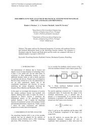
The THERMOSTATIC FUEL GAUGE, SELF-REGULATING (fig. 2-77), contains<br />
an electrically heated bimetallic strip that is linked to a pointer. A bimetallic strip<br />
consists of two dissimilar metals that, when heated, expand at different rates, causing it<br />
to deflect or bend. In the case of this gauge, the deflection of the bimetallic strip results<br />
in the movement of the pointer, causing the gauge to give a reading. The sending unit<br />
consists of a hinged arm with a float on the end. The movement of the arm controls a<br />
grounded point that makes contact with another point which is attached to an<br />
electrically heated bimetallic strip. The heating coils in the tank and the gauge are<br />
connected to each other in series.<br />
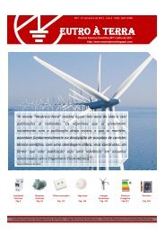
The THERMOSTATIC FUEL GAUGE, EXTERNALLY REGULATED (fig. 2-78),<br />
differs from a self-regulating system in the use of a variable resistance fuel tank<br />
sending unit and an external voltage-limiting device. The sending unit controls the<br />
gauge through the use of a rheostat (wire wound resistance unit whose value varies<br />
with its effective length). Theeffective length of the rheostat is controlled in the<br />
sending unit by a sliding brush that is operated by the float arm. The power supply to<br />
the gauge is kept constant through the use of a voltage limiter. The voltage limiter<br />
consists of a set of contact points that are controlled by an electrically heated<br />
bimetallic arm.<br />
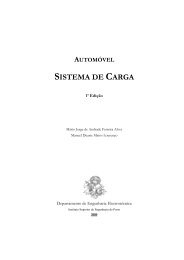
The THERMOSTATIC FUEL GAUGE, DIFFERENTIAL TYPE (fig. 2-79), is similar<br />
to the other type of thermostatic fuel gauges, except that it uses two electrically heated<br />
bimetallic strips that share equally in operating and supporting the gauge pointer.<br />
The pointer position is obtained by dividing the available voltage between the two<br />
strips (differential). The tank unit is a rheostat type similar to that already described;<br />
however, it contains a wire-wound resistor that is connected between external<br />
terminals of one of the gauges of the bimetallic strip. The float arm moves a grounded<br />
brush that raises resistance progressively to one terminal, while lowering resistance to<br />
the other. This action causes the voltage division and resulting heat differential to the<br />
gauge strips formulating the gauge reading.<br />
The MAGNETIC FUEL GAUGE (fig. 2-80) consists of a pointer mounted on an<br />
armature. Depending upon the design, the armature may contain one or two poles. The<br />
gauge is motivated by a magnetic field that is created by two separate magnetic coils<br />
that are contained in the gauge. One of these coils is connected directly to the battery,<br />
producing a constant magnetic field. The other coil produces a variable field, whose<br />
strength is determined by a rheostat-type tank unit. The coils are placed 90 degrees<br />
apart.<br />
<strong>AUTOMOTIVE</strong> <strong>ELECTRICAL</strong> <strong>CIRCUITS</strong> <strong>AND</strong> <strong>WIRING</strong> 89/ 101