AUTOMOTIVE ELECTRICAL CIRCUITS AND WIRING
AUTOMOTIVE ELECTRICAL CIRCUITS AND WIRING
AUTOMOTIVE ELECTRICAL CIRCUITS AND WIRING

Create successful ePaper yourself
Turn your PDF publications into a flip-book with our unique Google optimized e-Paper software.
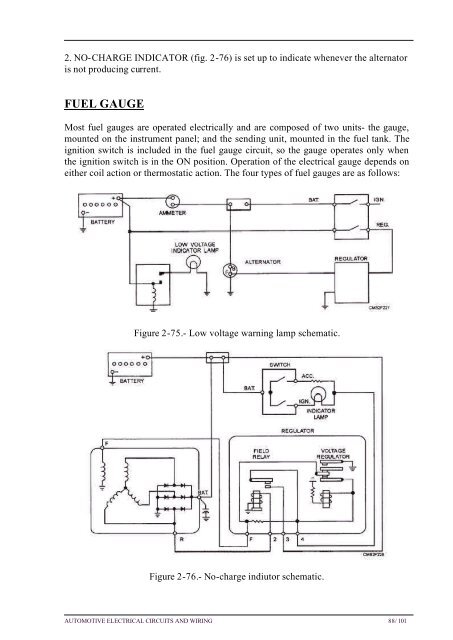
2. NO-CHARGE INDICATOR (fig. 2-76) is set up to indicate whenever the alternator<br />
is not producing current.<br />
FUEL GAUGE<br />
Most fuel gauges are operated electrically and are composed of two units- the gauge,<br />
mounted on the instrument panel; and the sending unit, mounted in the fuel tank. The<br />
ignition switch is included in the fuel gauge circuit, so the gauge operates only when<br />
the ignition switch is in the ON position. Operation of the electrical gauge depends on<br />
either coil action or thermostatic action. The four types of fuel gauges are as follows:<br />
Figure 2-75.- Low voltage warning lamp schematic.<br />
Figure 2-76.- No-charge indiutor schematic.<br />
<strong>AUTOMOTIVE</strong> <strong>ELECTRICAL</strong> <strong>CIRCUITS</strong> <strong>AND</strong> <strong>WIRING</strong> 88/ 101