AUTOMOTIVE ELECTRICAL CIRCUITS AND WIRING
AUTOMOTIVE ELECTRICAL CIRCUITS AND WIRING
AUTOMOTIVE ELECTRICAL CIRCUITS AND WIRING

Create successful ePaper yourself
Turn your PDF publications into a flip-book with our unique Google optimized e-Paper software.
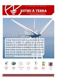
gears engage and when the engine kicks back due to ignition. When the engine starts<br />
and runs on its own power, the ring gear drives the pinion at a higher speed than does<br />
the starter. This action causes the pinion to turn in the opposite direction on the<br />
threaded sleeve and automatically disengages from the ring gear. This prevents the<br />
engine from driving the starter.<br />
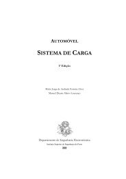
The OVERRUNNING CLUTCH (fig. 2-39) provides positive meshing and demeshing<br />
of the starter motor pinion gear and the ring gear. The starting motor armature shaft<br />
drives the shell and sleeve assembly of the clutch. The rotor assembly is connected to<br />
the pinion gear which meshes with the engine ring gear. Spring-loaded steel rollers are<br />
located in tapered notches between the shell and the rotor. The springs and plungers<br />
hold the rollers in position in the tapered notches. When the armature shaft turns, the<br />
rollers are jammed between the notched surfaces, forcing the inner and outer members<br />
of the assembly to rotate as a unit and crank the engine.<br />
Figure 2-38.- Starting motor with a Bendix drive.<br />
Figure 2-39.- Typical overrunning clutch.<br />
After the engine is started, the ring gear rotates faster than the pinion gear, thus<br />
tending to work the rollers back against the plungers, and thereby causing an<br />
overrunning action. This action prevents excessive speed of the starting motor. When<br />
the starting motor is released, the collar and spring assembly pulls the pinion out of<br />
mesh with the ring gear.<br />
<strong>AUTOMOTIVE</strong> <strong>ELECTRICAL</strong> <strong>CIRCUITS</strong> <strong>AND</strong> <strong>WIRING</strong> 45/ 101