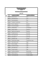
Design Of Digital Circuits - Dharmsinh Desai University
Design Of Digital Circuits - Dharmsinh Desai University
Design Of Digital Circuits - Dharmsinh Desai University

Create successful ePaper yourself
Turn your PDF publications into a flip-book with our unique Google optimized e-Paper software.
<strong>Design</strong> <strong>Of</strong> <strong>Digital</strong> <strong>Circuits</strong> Lab Manual<br />
3.3 Implementing the Solution:<br />
D Flip-Flop: -<br />
The R –S Flip flop has two data inputs R & S.<br />
Generation of two signals to drive a flip flop is a disadvantage in much application.<br />
Furthermore, the forbidden condition of both R and S high may occur inadvertently.<br />
This has lid to the D Flip Flop a circuit that needs only a single data input.<br />
Fig shows the simple diagram of D Flip- Flop using NOR Gate.<br />
In this circuit the D input is just transferred to the output e.g. If D =0 then output Q is<br />
also & If D = 1 output is also 1, as shown in the truth table.<br />
J-K Flip-flop:-<br />
JK Flip-Flop is the most versatile binary strange element.<br />
It can perform all the functions of SR and D flip-flop. The uncertainty in the State of SR Flip- Flop<br />
when S = R = 1 can be eliminated by using JK Flip-Flop<br />
‣ Procedure: -<br />
1. Study the circuit diagram.<br />
2. Connect the circuit as shown in fig i.e. JK Flip Flop by using connecting wires.<br />
3. Switch ‘ON’ the power supply.<br />
4. Apply proper I/P to J & K I/Ps of Flip-Flop from Logic I/P<br />
5. Check the O/P on Logic O/P Section.<br />
6. Change the I/P & Verify the Truth Table.<br />
T Flip –Flop: -<br />
The basic digital memory circuit is known as flip flop.<br />
It two stable states which are known as the 1 state 0 state. It can be obtained by using NAND or NOR<br />
gates.<br />
Generally there are two inputs to the flip flops (R, S or J K) and two outputs Q and Q.<br />
The outputs Q and Q are always complementary. The circuit has two stable state Q=1which is<br />
referred to as the 1 state( or set state ) whereas in the other stable state Q=0 which is referred to as the<br />
0 sate ( or reset state )<br />
If the circuit is in 1 state. It continues to remain in this state and similarly if it is in 0 state, it continues<br />
to remain in this state.<br />
This property of the circuit is referred to as memory, that is it can store 1 bit of digital information.<br />
In a JK flip flop, if J=K the resulting flip flop is referred to as a T Flip Flop, as shown in fig.<br />
It has only input, referred to as T input. Its truth table is given in table 1. If T=1 it acts as a toggle<br />
witch for every clock pulse the output Q changes.<br />
Department of Information Technology, Faculty of Technology, D. D. <strong>University</strong>, Nadiad.<br />
44