Design Of Digital Circuits - Dharmsinh Desai University
Design Of Digital Circuits - Dharmsinh Desai University
Design Of Digital Circuits - Dharmsinh Desai University

You also want an ePaper? Increase the reach of your titles
YUMPU automatically turns print PDFs into web optimized ePapers that Google loves.
<strong>Design</strong> <strong>Of</strong> <strong>Digital</strong> <strong>Circuits</strong> Lab Manual<br />
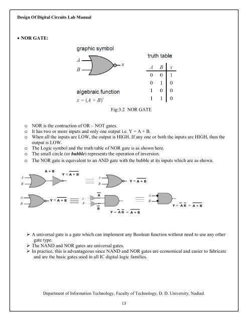
NOR GATE:<br />
Fig:3.2 NOR GATE<br />
o NOR is the contraction of OR – NOT gates.<br />
o It has two or more inputs and only one output i.e. Y = A + B.<br />
o When all the inputs are LOW, the output is HIGH. If any one or both the inputs are HIGH, then the<br />
output is LOW.<br />
o The Logic symbol and the truth table of NOR gate is as shown here.<br />
o The small circle (or bubble) represents the operation of inversion.<br />
o The NOR gate is equivalent to an AND gate with the bubble at its inputs which are as shown.<br />
‣ A universal gate is a gate which can implement any Boolean function without need to use any other<br />
gate type.<br />
‣ The NAND and NOR gates are universal gates.<br />
‣ In practice, this is advantageous since NAND and NOR gates are economical and easier to fabricate<br />
and are the basic gates used in all IC digital logic families.<br />
Department of Information Technology, Faculty of Technology, D. D. <strong>University</strong>, Nadiad.<br />
13