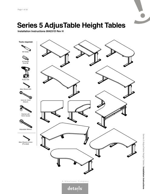
Series 5 AdjusTable Height Tables - Steelcase
Series 5 AdjusTable Height Tables - Steelcase
Series 5 AdjusTable Height Tables - Steelcase

Create successful ePaper yourself
Turn your PDF publications into a flip-book with our unique Google optimized e-Paper software.
Page 1 of 32<br />
<strong>Series</strong> 5 <strong>AdjusTable</strong> <strong>Height</strong> <strong>Tables</strong><br />
Installation Instructions 004231D Rev H<br />
Tools required:<br />
Bit Holder<br />
#2 Square<br />
Drive Bit<br />
Power Drill<br />
Allen Wrench-M3<br />
10mm & 14mm<br />
Wrench<br />
Ratchet with<br />
10mm Socket<br />
Adjustable Wrench<br />
Allen Wrench-2.5mm<br />
(Provided)<br />
<strong>Series</strong> 5 <strong>AdjusTable</strong> <strong>Height</strong> <strong>Tables</strong> | Installation Instructions
Page 2 of 32<br />
004231D Rev H<br />
TABLE OF CONTENTS:<br />
PAGE(S):<br />
Lets Get Started!............................................................................................3<br />
Which Legs Go Where?.................................................................................4<br />
Determine Leg Positions on your Table.........................................................5<br />
Overhangs and Custom Leg Positions..........................................................5<br />
Mounting Legs to Worksurfaces.................................................................... 6<br />
Determine Switch Position on your Table...................................................... 7<br />
90 o Corner <strong>Tables</strong>..........................................................................................8<br />
Left-Hand <strong>Tables</strong>............................................................................................9<br />
For 90 o <strong>Tables</strong> and P-<strong>Tables</strong>..........................................................................10<br />
For 120 o <strong>Tables</strong> and Bubble-Jetty <strong>Tables</strong>...................................................... 10<br />
Identify the Master and Slave Motors............................................................11<br />
Installing Motors and Synchronizing Legs.....................................................12<br />
Driveshafts and Leg Synchronization............................................................12<br />
Installing Driveshafts - All Versions................................................................13<br />
Installing Driveshafts - Compression Nut Version..........................................14<br />
Installing Driveshafts - Cap Nut & Push Nut Version.....................................15 through 17<br />
Installing Switch & Power Supply...................................................................18<br />
Attach Driveshaft Covers and Wire Managers...............................................19<br />
Installing Stretchers.......................................................................................20 & 21<br />
Connect and Route All Cables.......................................................................22<br />
Finishing the Table Assembly.........................................................................23<br />
Appendix A: 2-Piece Worksurface Assembly.................................................24 & 25<br />
Appendix B: Installing a Keyboard Mechanism for Bi-Level Worksurfaces... 26 through 32<br />
Overview of Assembly Process<br />
1) Decide on the table configuration.<br />
2) Assemble 2-piece worksurface or bi-level mechanism (if applicable).<br />
3) Attach legs to worksurface (with worksurface upside-down).<br />
4) Assemble motors, power supply, and gearbox (if applicable).<br />
5) Synchronize legs and add driveshaft(s).<br />
6) Add stretcher(s) and decorative parts.<br />
7) Add driveshaft cover(s) and wire manager(s).<br />
8) Connect and route all cables, mount switch.<br />
9) Flip table upright and test function.<br />
10) Level and clean it up.<br />
11)<br />
PLEASE LEAVE THESE INSTRUCTIONS, AND<br />
THE USER GUIDE, IN AN OBVIOUS PLACE<br />
FOR THE END USER AFTER ASSEMBLY.
Page 3 of 32<br />
004231D Rev H<br />
Let's Get Started!<br />
1<br />
Prepare a large open space to assemble the table.<br />
• Sweep the floor! Screws and small parts can damage<br />
the worksurface.<br />
• Put down a CLEAN shipping blanket to protect the worksurface.<br />
1<br />
2<br />
Unpack the worksurface and place on the shipping blanket upside-down.<br />
• REMEMBER - You're looking at the UNDERSIDE of the worksurface.<br />
Are you sure which side is left or right?<br />
2<br />
3<br />
Assembling a 90 o corner table with a 2-piece worksurface?<br />
Jump to Appendix 'A' now.<br />
3<br />
4<br />
Assembling a monitor-keyboard worksurface with a bi-level mechanism?<br />
Jump to Appendix 'B' now.<br />
4
Page 4 of 32<br />
004231D Rev H<br />
Which Legs Go Where?<br />
Leg Types:<br />
NOTE: Extra studs.<br />
NOTE: Extra studs.<br />
10" Standard 21" Standard 26" Standard 10" Corner 21" Corner<br />
21" Std. 21" Std. 26" Std. 26" Std. 26" Std. 26" Std.<br />
23"D Rectangle 23"D Bullet 29"D Rectangle 29"D Bullet Concave Taper-Flat<br />
21" Std. 21" Std.<br />
26" Std. 26" Std.<br />
26" Std.<br />
21" Std.<br />
10" Corner<br />
40" 90 o 40" 90 o Bi-Level<br />
46" 90 o 46" 90 o Bi-Level Rectangle Bi-Level 90 o 3-Leg<br />
10" Std.<br />
21" Corner<br />
P-Table<br />
21" Std.<br />
21" Std.<br />
10" Std. 21" Std.<br />
10" Std.<br />
120 o Bubble-Jetty
Page 5 of 32<br />
004231D Rev H<br />
RIGHT-HAND OVERHANG<br />
Determine Leg Positions on your Table:<br />
• Many <strong>Series</strong> 5 tables allow multiple leg postions, providing flexibility to<br />
maximize leg space, and allow overhangs for CPU slings and mobile<br />
pedestal placement.<br />
• The smallest tables may not allow for larger worksurface overhangs.<br />
(The standard overhang is 1-1/4".)<br />
• The mid-size tables may allow for a single 15" overhang.<br />
• The largest tables may be capable of allowing dual 15" overhangs.<br />
(One on each side.)<br />
• Refer to the Details specification guide for the capabilities of your specific table.<br />
LEFT-HAND OVERHANG<br />
NO OVERHANGS<br />
Overhangs and Custom Leg Positions:<br />
• Details provides pilot holes in worksurfaces that result in the<br />
standard overhangs (1-1/4" and 15"), as well as a clearance at<br />
1-1/4"<br />
the back to avoid pinch-points and provide for cable drop. OVERHANG<br />
Front View:<br />
15"<br />
1"<br />
CABLE<br />
AND<br />
PINCH-POINT<br />
CLEARANCE<br />
Side View:<br />
Standard Mounting Plate Positions:<br />
(Bottom View)<br />
Front of Wksf.<br />
(User Edge)<br />
Front of Wksf.<br />
(User Edge)<br />
0.769"<br />
OFFSET<br />
Back of Wksf.<br />
1-1/4"<br />
OVERHANG<br />
Back of Wksf.<br />
15"<br />
OVERHANG<br />
0.769"<br />
OFFSET<br />
Legs may be mounted on the worksurface<br />
in locations other than the factory default,<br />
provided that:<br />
• The overhangs DO NOT exceed 15".<br />
• All screws are at least 1" from outside edges.<br />
• All provided components still fit together (stretchers, driveshafts).<br />
• No safety hazards are posed to the end users or installers.<br />
1.769"<br />
(NO CABLE / PINCH-POINT<br />
CLEARANCE, BACK OF<br />
FOOT FLUSH WITH BACK<br />
OF WORKSURACE)<br />
9"<br />
CUSTOM<br />
OVERHANG
Page 6 of 32<br />
004231D Rev H<br />
Mounting Legs to Worksurfaces<br />
Mounting Plate<br />
Worksurface<br />
Pilot Holes<br />
NOTCH IS ALWAYS<br />
AT BACK OF LEG<br />
(BACK OF TABLE)<br />
= PILOT HOLE<br />
= NO PILOT HOLE PROVIDED<br />
Raise leg all the way up.<br />
This will allow access to the screws<br />
adjacent to the inner column.<br />
FOR EASIER<br />
ACCESS<br />
FOR EASIER<br />
ACCESS<br />
Align each leg with the pilot holes in the desired<br />
location, in the correct orientation. Attach each<br />
leg with ten (10) of the provided #10 x 1.075 long<br />
screws. These screws have a special drill-point,<br />
making them easy to drive in without a pilot hole.<br />
CAUTION: All holes in the leg mounting plates MUST<br />
be filled with screws. Failure to install all screws may<br />
result in structural instability.
Page 7 of 32<br />
004231D Rev H<br />
Determine Switch Position on your Table:<br />
• The switch can be located on either on either side of your table,<br />
but the switch comes with a short cable to minimize clutter. So,<br />
be sure to always locate the master motor near the switch location.<br />
NOTE: It does not matter which side of the table the master or<br />
slave motor goes on. This applies to all tables.<br />
Switch & Master Motor on Right:<br />
Switch & Master Motor on Left:<br />
SLAVE MOTOR<br />
MASTER MOTOR<br />
MASTER MOTOR<br />
SLAVE MOTOR<br />
SWITCH<br />
SWITCH
Page 8 of 32<br />
004231D Rev H<br />
90 o Corner <strong>Tables</strong><br />
90 o corner tables are available either as right-hand or left-hand tables.<br />
In order to go from right-hand to left-hand configurations, three (3) items must be changed:<br />
1) Orientation of center leg<br />
2) Placement of stretchers<br />
3) Configuration of intermediate gearbox (See page 9)<br />
The gearboxes ship from the factory set up for right-hand tables.<br />
Orientation of the center leg and placement of stretchers are controlled by the installer.<br />
10" and 21" corner legs are marked with "L" and "R" labels.<br />
The correct letter must be visible per the diagram.<br />
Otherwise, the center leg would go UP when the other legs would go DOWN, and vice-versa.<br />
Equal-Sized and Right-Hand <strong>Tables</strong> (Factory Default)<br />
NOTE: Equal-Sized 90 o and Equal-Sized 120 o Corner <strong>Tables</strong> are designed as right-hand tables by default.<br />
INTERMEDIATE<br />
GEARBOX<br />
SHORT SIDE<br />
ON LEFT<br />
LONG SIDE<br />
ON RIGHT<br />
"L" FACES IN<br />
CENTER LEG<br />
SPECIAL STRETCHER<br />
SLAVE MOTOR<br />
SWITCH<br />
MASTER MOTOR
Page 9 of 32<br />
004231D Rev H<br />
Left-Hand <strong>Tables</strong><br />
INTERMEDIATE<br />
GEARBOX<br />
NOTE: Switch & master motor can still be placed on<br />
either right-hand or left-hand side, regardless of<br />
whether it is a left-hand or right-hand table.<br />
SHORT SIDE<br />
ON RIGHT<br />
LONG SIDE<br />
ON LEFT<br />
"R" FACES IN<br />
CENTER LEG<br />
SPECIAL<br />
STRETCHER<br />
SWITCH<br />
SLAVE MOTOR<br />
MASTER MOTOR<br />
BRACKET<br />
1 2 Changing Orientation of Center Leg and Placement<br />
of Stretchers: See Diagram Above.<br />
NOTE: Subsequent pages of this document show assembly of the<br />
right-hand table configuration.<br />
a<br />
NUT<br />
BLACK<br />
BLUE<br />
3<br />
Changing Orientation of Intermediate Gearbox:<br />
Gearbox is supplied from the factory for right-handed applications.<br />
If installing the gearbox on a left-handed application, remove nuts<br />
and bolts and gearbox from the bracket (a). Turn gearbox 180 o<br />
so the blue portion of the gearbox is on the left (b). Re-install<br />
gearbox into bracket and attach the nuts and bolts (c).<br />
BOLT<br />
b<br />
GEARBOX<br />
Equal-Sized and<br />
Right-Hand <strong>Tables</strong><br />
Application<br />
(factory default)<br />
Left-Hand Table<br />
Application<br />
BLACK<br />
BLUE<br />
BLUE<br />
BLACK<br />
c<br />
BLUE<br />
BLACK
Page 10 of 32<br />
004231D Rev H<br />
For 90 o <strong>Tables</strong> and P-<strong>Tables</strong><br />
Attach the intermediate gearbox near the center leg using the<br />
provided pilot holes.<br />
NOTE: The gearbox must be inverted for left-hand<br />
tables. See page 9.<br />
(Equal-Sized or<br />
Right-Hand Table<br />
Shown This View)<br />
LONG SIDE<br />
SHORT SIDE<br />
For 120 o <strong>Tables</strong> and Bubble-Jetty <strong>Tables</strong><br />
In the center leg, insert the short (4") driveshaft,<br />
and attach a universal joint to each end. Tighten<br />
set screws on the universal joints with the<br />
provided hex wrench.<br />
4" DRIVESHAFT<br />
UNIVERSAL JOINT<br />
UNIVERSAL JOINT
Page 11 of 32<br />
004231D Rev H<br />
Identify the Master and Slave Motors<br />
The master motor and slave motor look the same,<br />
except for the connection panel at the back.<br />
NOTE: The power supply converts 120V AC<br />
from the wall outlet to 24V DC. The series 5<br />
motors operate on 24V DC.<br />
Slave<br />
Master<br />
Rear View<br />
Slave<br />
Master<br />
4-WIRE CONNECTOR<br />
TO SLAVE MOTOR<br />
RJ-11 SOCKET<br />
FROM SWITCH<br />
2-WIRE CONNECTOR<br />
FROM POWER SUPPLY<br />
SINGLE 4-WIRE<br />
CONNECTOR FROM<br />
MASTER MOTOR<br />
IMPORTANT! The master motor has one other key difference.<br />
It also has a hidden kill switch. This kill switch is inside the<br />
front mounting hole. If the front mounting bolt is not properly<br />
installed, the table will not operate!<br />
FRONT MOUNTING HOLE<br />
CORRECT!<br />
WRONG!<br />
(Table will not operate)<br />
KILL SWITCH<br />
MOUNTING<br />
BOLT<br />
NO MOUNTING<br />
BOLT
1<br />
Page 12 of 32<br />
004231D Rev H<br />
Installing Motors and Synchronizing Legs<br />
Determine on which side of the table<br />
each motor will go. (see page 5)<br />
Install M6 x 80 bolts & M6 nuts to<br />
each motor as shown.<br />
Master Motor<br />
Example: Master motor and switch<br />
on user's right-hand side.<br />
1<br />
Slave Motor<br />
2<br />
Insert the exposed stud from each motor<br />
through the spacer, and then into the side<br />
mounting slot of the outboard leg mounting<br />
plates. Install M6 nut, but DO NOT TIGHTEN<br />
(leave motor loose).<br />
M6 NUT<br />
M6 x 80 BOLT<br />
NOTE: Install motors to outboard legs on 3-leg<br />
tables. Do not install a motor to the center leg.<br />
2<br />
MOTOR<br />
NO MOTOR<br />
MOTOR<br />
M6 NUT<br />
EXPOSED STUD<br />
SPACER<br />
Driveshafts and Leg Synchronization<br />
<strong>Series</strong> 5 legs and motors must be synchronized<br />
before installing the driveshafts.<br />
<strong>Series</strong> 5 motors are shipped from the factory in the<br />
"all the way down" position.<br />
Before inserting the driveshafts, ensure ALL LEGS<br />
are pushed all the way down (fully compressed).
Page 13 of 32<br />
004231D Rev H<br />
Installing Driveshafts - All Versions<br />
1<br />
Insert hex shafts into driveshaft tube. Leave<br />
compression nuts loose.<br />
NOTE: On 3-leg tables, be sure to use the<br />
correct length of driveshaft for the particular<br />
side of the worksurface. Use longer components<br />
on the long side, and shorter components on the<br />
short side, where applicable.<br />
LONG PARTS<br />
FOR LONG SIDE<br />
SHORT PARTS<br />
FOR SHORT SIDE<br />
1<br />
or<br />
2<br />
With all table legs pushed all the way down,<br />
insert driveshafts through gearboxes and legs.<br />
2<br />
3<br />
If the hexagon openings are not perfectly aligned, grip<br />
the driveshaft with an adjustable wrench and rotate<br />
slightly, until the driveshaft slides through with ease.<br />
NOTE: DO NOT pound the driveshafts through with a<br />
hammer. This will mushroom the end of the driveshaft.<br />
3
Page 14 of 32<br />
004231D Rev H<br />
Installing Driveshafts (cont.) - Compression Nut Version<br />
4<br />
At each outboard leg, slide the driveshaft through until<br />
it is fully-engaged with leg, but not protruding out.<br />
5<br />
Peel away paper backing (5a) and carefully<br />
apply decorative caps at each exposed<br />
opening with firm pressure (5b).<br />
5a<br />
PAPER BACKING<br />
END CAP<br />
STOP WHEN<br />
DRIVESHAFT<br />
IS VISIBLE.<br />
4<br />
5b<br />
6<br />
Once all driveshafts are installed, tighten all remaining<br />
compression nuts with 40 to 50 in-lbs of torque to avoid<br />
stripping the threads. (Tighten compression nut as much<br />
as possible with fingers, then tighten about 1/4 turn with<br />
wrench.)<br />
TWO NUTS<br />
PER MOTOR<br />
1<br />
2<br />
1/4 TURN<br />
6a<br />
6b<br />
COMPRESSION NUT<br />
7<br />
Tighten the motor mounting nuts.<br />
7
Page 15 of 32<br />
004231D Rev H<br />
Installing Driveshafts (cont.) - Cap Nut & Push Nut Version<br />
2-Leg <strong>Tables</strong> & 120 o <strong>Tables</strong><br />
Driveshafts are retained using cap nuts, which<br />
grip the driveshaft ends and prevent them from<br />
backing out of the legs.<br />
2-leg tables, 120 o tables & bubble-jetty tables<br />
require one cap nut mounted outside of each<br />
leg. The driveshaft assembly is thus retained<br />
in both directions.<br />
CAP NUT<br />
(with plastic cover)<br />
2-Leg <strong>Tables</strong>:<br />
PUSH NUT<br />
CAP<br />
NUT<br />
CAP<br />
NUT<br />
120 o <strong>Tables</strong>:<br />
CAP<br />
NUT<br />
CAP<br />
NUT<br />
4<br />
Place cap nut on a flat, hard surface and push<br />
driveshaft into it.<br />
Feed driveshaft through leg, from outside, until<br />
cap nut bottoms out on leg.
Page 16 of 32<br />
004231D Rev H<br />
Installing Driveshafts (cont.) - Cap Nut & Push Nut Version<br />
90 o <strong>Tables</strong> & P-<strong>Tables</strong><br />
3-leg tables & P-<strong>Tables</strong> require one cap nut<br />
mounted outside of each leg, plus a push<br />
nut mounted on the inside of the leg that is<br />
perpendicular to the other 2 legs, i.e. across<br />
from the intermediate gearbox.<br />
CAP NUT<br />
(with plastic cover)<br />
PUSH NUT<br />
90 o <strong>Tables</strong>:<br />
INTERMEDIATE<br />
GEARBOX<br />
P-<strong>Tables</strong>:<br />
INTERMEDIATE<br />
GEARBOX<br />
CAP<br />
NUT<br />
CAP<br />
NUT<br />
CAP<br />
NUT<br />
PUSH<br />
NUT<br />
PUSH<br />
NUT<br />
5<br />
CAP NUT<br />
CAP NUT<br />
To install the push nut, follow steps on previous page. Locate correct<br />
location per above diagrams. Temporarily remove the motor (5a).<br />
Install push nut on free end of driveshaft (5b).<br />
5a<br />
5b<br />
6<br />
Using a adjustable wrench or pliers to<br />
assist, push the push nut all the way down<br />
the length of the driveshaft until it meets<br />
the inside of the lifting column.<br />
6
Page 17 of 32<br />
004231D Rev H<br />
Installing Driveshafts (cont.) - Cap Nut & Push Nut Version<br />
7 Reinstall motor.<br />
7<br />
8<br />
Ensure all driveshafts are inserted into driveshaft<br />
tubes. Tighten set screws gently to avoid stripping<br />
threads with provided hex wrench.<br />
8<br />
9<br />
Tighten the motor mounting nuts.<br />
9<br />
10<br />
Where applicable, attach driveshaft stabilizer brackets<br />
with two (2) screws each, using provided pilot holes.<br />
10
Page 18 of 32<br />
004231D Rev H<br />
Straight:<br />
POWER SUPPLY<br />
Installing Switch & Power Supply<br />
1<br />
Locate the two (2) pilot holes for mounting the<br />
power supply. Partially install two (2) #8-15 x 5/8"<br />
screws per the diagram shown below.<br />
NOTE: Use the pre-drilled pilot holes to mount<br />
the power supply in a way that assures<br />
accessories can be clamped to the<br />
worksurface, and allow all cables to reach.<br />
If a different power supply location is desired,<br />
use the template below, which matches the<br />
the power supply's keyhole slots and 122mm<br />
hole spacing.<br />
90º:<br />
1<br />
POWER SUPPLY<br />
2<br />
Fit the keyhole slots of the power supply over<br />
the screws, and slide over into place.<br />
POWER SUPPLY<br />
120º:<br />
2<br />
3<br />
Attach the switch at the front of the worksurface,<br />
adjacent to the leg with the master motor. Use<br />
the pre-drilled pilot holes for proper switch position,<br />
and affix with two (2) #8-15 x 5/8" screws.<br />
MASTER MOTOR<br />
SWITCH<br />
3<br />
Template for Power Supply:<br />
Template Power Supply<br />
<br />
2x<br />
Ø4mm<br />
4mm
Page 19 of 32<br />
004231D Rev H<br />
Attach Driveshaft Covers and<br />
Wire Managers<br />
1<br />
Determine which driveshaft cover goes where, if<br />
applicable. Attach driveshaft covers using four (4)<br />
screws each, into the pre-drilled pilot holes.<br />
NOTE: There should be about 1/4" between the<br />
motors and the driveshaft covers.<br />
1a<br />
LONG COVER<br />
LONG SIDE<br />
SHORT SIDE<br />
SHORT COVER<br />
~ 1/4"<br />
TWO SCREWS<br />
PER SIDE<br />
1b<br />
DRIVESHAFT<br />
COVER<br />
MOTOR<br />
ALIGN HOLES IN COVER<br />
WITH PILOT HOLES IN<br />
WORKSURFACE.<br />
2<br />
To maximize available space on the back of the<br />
worksurface for clamping accessories, place the<br />
wire manager over the driveshaft cover as shown.<br />
Attach with either two (2) or three (3) screws.<br />
No pilot holes are provided for wire managers.<br />
2<br />
WIRE MANAGER<br />
WIRE MANAGER IS<br />
PUSHED UP AGAINST<br />
DRIVESHAFT COVER.<br />
BACK OF<br />
WORKSURFACE
Page 20 of 32<br />
004231D Rev H<br />
Installing Stretchers<br />
NOTE: On 3-leg tables, be sure to use the correct length<br />
of stretcher for the particular side of the worksurface.<br />
Use longer components on the long side and shorter<br />
components on the short side, where applicable.<br />
SHORT PARTS<br />
FOR SHORT SIDE<br />
LONG PARTS<br />
FOR LONG SIDE<br />
1<br />
Sub-assemble stretchers as shown. For 90 o<br />
stretcher, place the decorative cover over the<br />
small tube first, then insert into large tube.<br />
Straight:<br />
NOTE: Wherever possible, ensure that the set<br />
screws face the floor after table is assembled<br />
and flipped upright.<br />
90º:<br />
1<br />
SET SCREWS TO<br />
FACE THE FLOOR.
Page 21 of 32<br />
004231D Rev H<br />
Installing Stretchers (cont.)<br />
2<br />
For 120 o and bubble-jetty tables, mount the<br />
center leg bracket as shown such that the set<br />
screws face the floor. Add decorative cover after<br />
tightening the two (2) M6 nuts.<br />
SET SCREWS TO<br />
FACE THE FLOOR.<br />
M6 NUTS<br />
2<br />
3<br />
For all other stretchers, mount the ends to the legs<br />
using two (2) nuts per connection. Place decorative<br />
covers over each end after assembly.<br />
Straight:<br />
M6 NUTS<br />
3<br />
M6 NUTS<br />
90º:<br />
4<br />
Gently tighten all set screws between stretcher tubes.<br />
4
Page 22 of 32<br />
004231D Rev H<br />
Connect and Route All Cables<br />
1<br />
Connect switch to master motor using the<br />
supplied RJ-11 cable.<br />
Switch<br />
1<br />
Master Motor<br />
2<br />
Connect master motor to slave motor using<br />
the supplied motor-to-motor cable.<br />
2<br />
3 Connect power supply to master motor with the<br />
cable already attached to the power supply.<br />
4<br />
Connect power cord to power supply.<br />
3<br />
CAUTION: Be sure to create a 'drip loop' in the<br />
power cord before making the connection to a<br />
live wall socket, to prevent electric shock if<br />
liquids spill on power cord.<br />
4<br />
5<br />
Route all cables through wire managers.<br />
Keep all cables clear of moving parts!
Page 23 of 32<br />
004231D Rev H<br />
Finishing the Table Assembly<br />
1<br />
Ensure all decorative trim caps are<br />
securely attached.<br />
1<br />
STRETCHER CAPS<br />
2<br />
3<br />
Double-check that all nuts, bolts, screws and<br />
compression nuts are securely attached.<br />
Flip each completed table right-side up and<br />
test the function of each completed table.<br />
Cycle the table all the way up and down to<br />
test for correct function.<br />
HOLE CAPS<br />
ASSEMBLY DIRECTION<br />
AND USER GUIDE<br />
4<br />
PLEASE LEAVE THESE INSTRUCTIONS, AND<br />
THE USER GUIDE, IN AN OBVIOUS PLACE<br />
FOR THE END USER AFTER ASSEMBLY.<br />
5<br />
Finally, adjust glides to level the table, both<br />
left to right and front to back.<br />
5<br />
5
Page 24 of 32<br />
004231D Rev H<br />
Appendix A: 2-Piece Worksurface Assembly<br />
1<br />
Position top pieces upside down on the assembly surface<br />
and align with wood spline (or biscuits) provided.<br />
Optional Biscuits<br />
1<br />
SPLINE<br />
2<br />
Install draw bolts and tighten with 5/16" or 7/16" open end<br />
wrench. Attach two (2) v-channels using sixteen (16) screws<br />
per channel.<br />
DRAW<br />
BOLTS<br />
SCREWS<br />
V-CHANNELS<br />
2
Page 25 of 32<br />
004231D Rev H<br />
Appendix A: 2-Piece Worksurface Assembly (cont.)<br />
Special Notes on 2-Piece Worksurfaces<br />
Overhangs:<br />
• The extension portion of 2-piece worksurfaces may<br />
not completely overhang the supporting leg!<br />
• One leg must always be fully mounted to the<br />
extension portion.<br />
WRONG!<br />
THIS CONDITION<br />
IS NOT ALLOWED!<br />
CORRECT!<br />
CORRECT!<br />
Planar Alignment:<br />
• The spline or biscuits between the primary and<br />
extension portions act to keep the worksurface<br />
halves aligned on the top surface.<br />
• If these parts fit loosely, shim them using pieces<br />
of paper as shown.<br />
PRIMARY HALF<br />
PRIMARY HALF<br />
PLANAR<br />
MIS-ALIGNMENT<br />
EXTENSION HALF<br />
SLOT<br />
FOLDED SHEETS<br />
OF PAPER TO SHIM<br />
SPLINE<br />
IMPROVED<br />
ALIGNMENT<br />
EXTENSION HALF
Page 26 of 32<br />
004231D Rev H<br />
Appendix B: Installing a Keyboard<br />
Mechanism for Bi-Level Worksurfaces<br />
1<br />
Prepare a large open space to assemble the table.<br />
• Sweep the floor! Screws and small parts can damage<br />
the worksurface.<br />
• Put down a CLEAN shipping blanket to protect the worksurface.<br />
1<br />
2<br />
Unpack the worksurface and place on the shipping blanket upside-down.<br />
• REMEMBER - You're looking at the UNDERSIDE of the worksurface.<br />
Are you sure which side is left or right?<br />
2<br />
3<br />
With the assembly inverted, arrange the "keyboard"<br />
portion of the worksurface face-down as shown.<br />
Be sure to place the user-edge toward the end user's<br />
position as shown.<br />
3<br />
USER EDGE<br />
1-1/2" GAP<br />
KEYBOARD PORTION<br />
OF WORKSURFACE
Page 27 of 32<br />
004231D Rev H<br />
Appendix B: Installing a Keyboard<br />
Mechanism for Bi-Level Worksurfaces (cont.)<br />
4<br />
Lower keyboard mechanism onto underside of worksurface<br />
as shown. Align with pilot holes on both portions of worksurface.<br />
4<br />
KEYBOARD<br />
MECHANISM<br />
5<br />
Insert screws into all available holes of mechanism<br />
(16 screws total).<br />
NOTE: Do not assemble brackets for pneumatic<br />
piston yet.<br />
5<br />
6<br />
Attach small spacer plate next to the arm<br />
attached to the piston. The spacer limits the<br />
travel of the mechanism to prevent<br />
interference with the driveshaft. Install the<br />
spacer, as shown, using the pre-drilled pilot<br />
holes.<br />
6<br />
SPACER PLATE<br />
NOTE: Spacer goes on user's<br />
left-hand side of mechanism.
Page 28 of 32<br />
004231D Rev H<br />
Appendix B: Installing a Keyboard<br />
Mechanism for Bi-Level Worksurfaces (cont.)<br />
NOTE: The pneumatic piston is pre-set at<br />
the factory for level installation (monitor and<br />
keyboard portion of worksurface in same<br />
horizontal plane). From this position, the<br />
piston must extend and compress, to allow<br />
the full range of motion of the mechanism.<br />
KEYBOARD<br />
LEVEL<br />
Piston at Mid-Range<br />
Side View of Piston<br />
KEYBOARD ALL<br />
THE WAY UP<br />
Piston Extended<br />
MAXIMUM EXTENSION<br />
KEYBOARD LEVEL<br />
KEYBOARD @<br />
MAXIMUM HEIGHT<br />
MAXIMUM<br />
COMPRESSION<br />
KEYBOARD @<br />
MINIMUM HEIGHT<br />
Piston Compressed<br />
KEYBOARD ALL<br />
THE WAY DOWN<br />
CAUTION: Do not depress button on the end of the<br />
pneumatic piston. If piston becomes fully extended,<br />
compress it prior to assembly by pushing down<br />
against hard floor, and very quickly rotating up, so<br />
that button pops back out before the piston has a<br />
chance to extend.
Page 29 of 32<br />
004231D Rev H<br />
Appendix B: Installing a Keyboard<br />
Mechanism for Bi-Level Worksurfaces (cont.)<br />
7<br />
8<br />
9<br />
Remove circlip from piston (7a) and remove piston from<br />
bracket. Assemble nut to threaded end of pneumatic<br />
piston (7b). Screw nut all the way down on the threads<br />
from the end (7c).<br />
Place threaded end of piston through smaller hole in<br />
top of bracket, exactly as shown. Note orientation of<br />
bracket.<br />
Feed end of cable through large hole of bracket (9a).<br />
Place spacer over threaded end of piston (9b).<br />
CIRCLIP<br />
7a<br />
7b<br />
PNEUMATIC<br />
PISTON<br />
8<br />
THREADED END<br />
OF PISTON<br />
7c<br />
NUT<br />
BRACKET<br />
9b<br />
9a<br />
END OF CABLE
Page 30 of 32<br />
004231D Rev H<br />
Appendix B: Installing a Keyboard<br />
Mechanism for Bi-Level Worksurfaces (cont.)<br />
10<br />
Align threaded hole in plastic actuator with threads on piston<br />
(10a), and screw piston into place (10b).<br />
10a<br />
NOTE: There should be about 3/8" of throw in the lever when<br />
asssembled correctly (10c).<br />
CAUTION: Be careful not to actuate the button on the end of<br />
the piston until assembly is complete. Refer to page 28.<br />
PLASTIC<br />
ACTUATOR<br />
11<br />
Place bracket on worksurface, and align with pilot holes (11a).<br />
The pilot holes place the bracket in the optimum location for<br />
correct mechanism function. Re-attach piston to linkage arm<br />
with circlip (11b). Secure using four (4) screws (11c).<br />
10b<br />
10c<br />
PISTON<br />
3/8"<br />
BRACKET<br />
11a<br />
PILOT HOLES<br />
CIRCLIP<br />
11b<br />
11c
Page 31 of 32<br />
004231D Rev H<br />
Appendix B: Installing a Keyboard<br />
Mechanism for Bi-Level Worksurfaces (cont.)<br />
Assembling Mechanism Actuator<br />
12<br />
13<br />
14<br />
Align mounting plate for actuator with pilot holes in keyboard<br />
portion of worksurface and install with two (2) screws.<br />
Place end of actuator cable in slot on underside of handle (13a).<br />
Turn handle over, align guide hooks with rails on mounting plate<br />
and slide handle over mounting plate (13b). Be sure the cable<br />
remains in the slot at the back of handle (13c).<br />
Place notched area of rubber cable overmold into notch of<br />
mounting plate and snap into place.<br />
12<br />
MOUNTING<br />
ACTUATOR<br />
END OF ACTUATOR<br />
CABLE<br />
RAIL<br />
13a<br />
13b<br />
UNDERSIDE OF<br />
HANDLE<br />
RAIL<br />
13c<br />
14
Page 32 of 32<br />
004231D Rev H<br />
Appendix B: Installing a Keyboard<br />
Mechanism for Bi-Level Worksurfaces (cont.)<br />
Motor Placement on Rectangular Bi-Level<br />
<strong>Tables</strong> with 2-Leg Base:<br />
ACTUATOR<br />
Rectangular Bi-Levels:<br />
SWITCH<br />
Rectangular bi-level table must still have the<br />
motors mounted in between the legs.<br />
For all bi-level tables, the switch and master<br />
motor must be mounted on the user's right-hand<br />
side. This is because the mechanism actuator<br />
must be mounted on the left-hand side and<br />
can't be moved.<br />
SLAVE MOTOR<br />
(INBOARD)<br />
MASTER MOTOR<br />
(INBOARD)<br />
Motor Placement on 90 o Small-Corner Bi-Level<br />
<strong>Tables</strong> with 2-Leg Base:<br />
90 o Small-Corner Bi-Levels:<br />
ACTUATOR<br />
SWITCH<br />
To allow space for the bi-level mechanism, the<br />
motors on all 90 o small-corner bi-level with a<br />
2-leg base must be mounted outboard of the<br />
legs as shown.<br />
SLAVE MOTOR<br />
(OUTBOARD)<br />
MASTER MOTOR<br />
(OUTBOARD)<br />
For Compression Nut Version:<br />
NOTE: For 90 o small-corner bi-level tables with 2-leg<br />
base only. The cosmetic caps that cover the ends of<br />
the driveshafts are not used and may be discarded.<br />
For Cap Nut / Push Nut Version:<br />
NOTE: For 90 o small-corner bi-level tables with<br />
2-leg base only. Apply cap nut to the end of the<br />
driveshaft as it protrudes from the motor.