xmega a3u - Elfa
xmega a3u - Elfa
xmega a3u - Elfa
You also want an ePaper? Increase the reach of your titles
YUMPU automatically turns print PDFs into web optimized ePapers that Google loves.
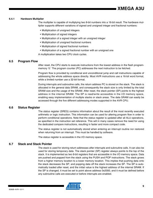
XMEGA A3U<br />
6.4.1 Hardware Multiplier<br />
The multiplier is capable of multiplying two 8-bit numbers into a 16-bit result. The hardware multiplier<br />
supports different variations of signed and unsigned integer and fractional numbers:<br />
• Multiplication of unsigned integers<br />
• Multiplication of signed integers<br />
• Multiplication of a signed integer with an unsigned integer<br />
• Multiplication of unsigned fractional numbers<br />
• Multiplication of signed fractional numbers<br />
• Multiplication of a signed fractional number with an unsigned one<br />
A multiplication takes two CPU clock cycles.<br />
6.5 Program Flow<br />
After reset, the CPU starts to execute instructions from the lowest address in the flash programmemory<br />
‘0.’ The program counter (PC) addresses the next instruction to be fetched.<br />
Program flow is provided by conditional and unconditional jump and call instructions capable of<br />
addressing the whole address space directly. Most AVR instructions use a 16-bit word format,<br />
while a limited number use a 32-bit format.<br />
During interrupts and subroutine calls, the return address PC is stored on the stack. The stack is<br />
allocated in the general data SRAM, and consequently the stack size is only limited by the total<br />
SRAM size and the usage of the SRAM. After reset, the stack pointer (SP) points to the highest<br />
address in the internal SRAM. The SP is read/write accessible in the I/O memory space,<br />
enabling easy implementation of multiple stacks or stack areas. The data SRAM can easily be<br />
accessed through the five different addressing modes supported in the AVR CPU.<br />
6.6 Status Register<br />
The status register (SREG) contains information about the result of the most recently executed<br />
arithmetic or logic instruction. This information can be used for altering program flow in order to<br />
perform conditional operations. Note that the status register is updated after all ALU operations,<br />
as specified in the instruction set reference. This will in many cases remove the need for using<br />
the dedicated compare instructions, resulting in faster and more compact code.<br />
The status register is not automatically stored when entering an interrupt routine nor restored<br />
when returning from an interrupt. This must be handled by software.<br />
The status register is accessible in the I/O memory space.<br />
6.7 Stack and Stack Pointer<br />
The stack is used for storing return addresses after interrupts and subroutine calls. It can also be<br />
used for storing temporary data. The stack pointer (SP) register always points to the top of the<br />
stack. It is implemented as two 8-bit registers that are accessible in the I/O memory space. Data<br />
are pushed and popped from the stack using the PUSH and POP instructions. The stack grows<br />
from a higher memory location to a lower memory location. This implies that pushing data onto<br />
the stack decreases the SP, and popping data off the stack increases the SP. The SP is automatically<br />
loaded after reset, and the initial value is the highest address of the internal SRAM. If<br />
the SP is changed, it must be set to point above address 0x2000, and it must be defined before<br />
any subroutine calls are executed or before interrupts are enabled.<br />
8386B–AVR–12/11<br />
9


