KIT 149 (version D/E) USB PIC PROGRAMMER - Kitsrus
KIT 149 (version D/E) USB PIC PROGRAMMER - Kitsrus
KIT 149 (version D/E) USB PIC PROGRAMMER - Kitsrus

Create successful ePaper yourself
Turn your PDF publications into a flip-book with our unique Google optimized e-Paper software.
<strong>KIT</strong> <strong>149</strong> (<strong>version</strong> D/E) <strong>USB</strong> <strong>PIC</strong> <strong>PROGRAMMER</strong><br />
This documentation written April 17, 2004.<br />
Kit <strong>149</strong>D has added the 10K resistor needed to program<br />
the 16F88 <strong>PIC</strong> chip supported with diypack22.zip (R25).<br />
It also has the 3 protection resistors, uses a <strong>USB</strong> ‘B’<br />
connector and adds a sixth pin to the header and harness<br />
for ICSP programming added earlier.<br />
the kit working then you can download the latest <strong>version</strong>,<br />
upgrade the firmware & run with the latest MicroPro.exe.<br />
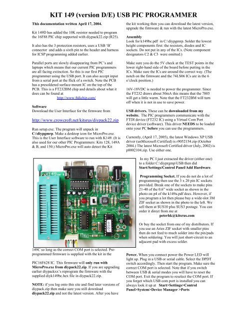
Assembly<br />
Look for k<strong>149</strong>bc.pdf in C:\diypgmrp. Solder the lowest<br />
height components first: the resistors, diodes and IC<br />
sockets. Do not put in any of the ICs. (Note component<br />
designators C2 & C3 were omitted.)<br />
Parallel ports are slowly disappearing from PC’s and<br />
laptops which means that our current <strong>PIC</strong> programmers<br />
are all facing extinction. So this is our first <strong>PIC</strong><br />
programmer using the <strong>USB</strong> port. It can also accept input<br />
from a serial port at the flick of a switch. Note the PCB<br />
has a presoldered surface-mount IC on the top of the<br />
PCB. This is a FT232BM chip and details about what it<br />
does can be found at<br />
http://www.ftdichip.com/<br />
Software<br />
Download the User Interface for the firmware from<br />
http://www.crowcroft.net/kitsrus/diypack22.zip<br />
Run setup.exe. The program will unpack in<br />
C:\diypgmrp. Make a desktop icon for MicroPro.exe.<br />
This is the User Interface software to run with K<strong>149</strong>. (It is<br />
also used for our other <strong>PIC</strong> Programmers: Kits 128, <strong>149</strong>A<br />
& B, and 150.) MicroPro.exe will auto detect the Kit<br />
Make sure you do the 5V check at the TEST points in the<br />
lower right-hand side of the board before putting in the<br />
ICs. Make sure the ICs are around the correct way. (The<br />
notch on the firmware and the 74LS06 ICs are in the 6<br />
o’clock position.)<br />
16V-18VDC is needed to power the programmer. Since<br />
the FT232 draws about 50mA this means that the 7805<br />
will get a little warm. Note that the FT232BM will turn<br />
off when it is not in use to save power.<br />
<strong>USB</strong> drivers. These can be downloaded from my<br />
website. The <strong>PIC</strong> programmers communicate with the<br />
FTDI device (FT232 IC) using a Virtual Com Port<br />
device driver (software). This driver NEEDS to be loaded<br />
onto your PC before you can use the programmers.<br />
Currently, (April 17, 2005), the latest Windows XP <strong>USB</strong><br />
driver (unMicrosoft Certified) is r9052154.zip (October<br />
2004.) The latest Microsoft Certified driver (July, 2002) is<br />
p8002104.zip. Use either one.<br />
In my PC I just extracted the driver (either one)<br />
to a folder C:\diyprgmp\<strong>USB</strong> then did<br />
Start/Settings/Control Panel/Add Hardware.<br />
Programming Socket. If you do not do a lot of<br />
programming then use the 3 x 20 pin IC sockets<br />
provided. Break one of the sockets to make pins<br />
21-40 of the 0.6” wide socket as shown in the<br />
photo on p4 of the k<strong>149</strong>a.pdf docs. However, if<br />
you program a lot then please buy a wide-slot 3M<br />
ZIF socket as shown in the photo to the left. We<br />
sell them at $US10 plus $US3 postage. You can<br />
order it direct from me at<br />
peterhk@kitsrus.com<br />
Or buy the socket from one of my distributors. If<br />
you use an Aries ZIF socket with smaller pins<br />
then do not feed to much solder into the pin/pads<br />
when soldering. You will just short-circuit to an<br />
adjacent pad with excess solder.<br />
<strong>149</strong>C so long as the correct COM port is selected. Preprogrammed<br />
firmware is supplied with the kit in the<br />
<strong>PIC</strong>16F628 IC. This firmware will only run with<br />
MicroPro.exe from diypack22.zip. If you are upgrading<br />
earlier diypackxx’s reprogram the firmware with the<br />
supplied diyk<strong>149</strong>bc.hex file in diypack22.zip.<br />
NOTE: if you log onto this site and find later <strong>version</strong>s of<br />
diypack.zip then make sure you still download<br />
diypack22.zip and not the latest <strong>version</strong>. After you have<br />
Power. When you connect power the Power LED will<br />
light up. Plug in a <strong>USB</strong> or serial cable. Select the DPDT<br />
switch accordingly. Then start the program. Make sure the<br />
correct COM port is selected. Note that if you switch<br />
between <strong>USB</strong> & serial modes you will have to reset the<br />
COM port. Exit the program to reselect the COM port. If<br />
you forget which <strong>USB</strong> com port is installed you can<br />
always look it up at Start>Settings>Control<br />
Panel>System>Device Manager >Ports
<strong>KIT</strong> <strong>149</strong> (<strong>version</strong> D/E) <strong>USB</strong> <strong>PIC</strong> <strong>PROGRAMMER</strong><br />
Note the ‘Fly Window’ under Options which allow<br />
K<strong>149</strong>D to be used with MPLAB when a new hex file is<br />
compiled.<br />
No-Keypress Programming. Flash chips are<br />
automatically erased in this mode if they are not blank.<br />
Known Bug. Switching between <strong>USB</strong> & Serial modes<br />
may indicate an error when the COM port is reset.<br />
However, the port, if correct, will in fact be properly<br />
Reset.<br />
COMPONENTS<br />
Resistors 5%, carbon<br />
27R red violet black R18 R19 2<br />
470R yellow violet brown R20 1<br />
1K brown black red R14 15 16 17 4<br />
1K5 brown green red R21 1<br />
2K2 red red red R1 R4 2<br />
3K3 orange orange red R2 R3 R24 3<br />
4K7 yellow violet red R11 R12 R13 R23 4<br />
10K brown black orange R5 6 7 8 9 10 22 25 8<br />
<strong>PIC</strong> Supported. For the list of <strong>PIC</strong>’s supported (which is<br />
changing all the time) go to Options/Edit Chip List. Or<br />
just click on the Chip Selector drop-down box and run<br />
through the list.<br />
ICSP. Click Options/ICSP Mode. Does not support low<br />
voltage programming. The LOW pin is an open collector<br />
output, which when active will pull the LOW pin to<br />
ground. It can be used in ICSP to hold the LVP pin low<br />
while programming, or the OSC1 pin, or any part on the<br />
target board which may need control (in this manner)<br />
during programming.<br />
jpg’s. The color <strong>version</strong> of the photo on the page above<br />
may be downloaded from<br />
http://www.kitsrus.com/jpg/k<strong>149</strong>b_1.jpg<br />
K<strong>149</strong>C dropped 1 10K resistor and adds 3 x 3K3<br />
resistors. It uses a <strong>USB</strong> ‘B’ connector and uses a 6 pin<br />
header and harness. K<strong>149</strong>D adds a 10K resistor.<br />
chipinfo.cid This is just a text file and you can add your<br />
own <strong>PIC</strong> chips to it if you understand and conform to the<br />
format. Note only one (not two or more) blank line<br />
between different <strong>PIC</strong> definitions. (In early <strong>version</strong>s of<br />
the micropro.exe this file was called chipinfo.dat but this<br />
cause compilation problems in W2000 so the name was<br />
changed.) Because new <strong>PIC</strong>’s are being released almost<br />
every month look regularly for new <strong>version</strong>s of the<br />
diypackxx.zip in<br />
http://www.kitsrus.com/upuc.html<br />
Upgrading. You can upgrade by buying and<br />
programming a second 628-20/P or 16F628A <strong>PIC</strong>, or if<br />
you have access to a second <strong>PIC</strong> programmer and<br />
reprogram the existing 628 in it.<br />
16F628A. About 2/2004 Microchip stopped production of<br />
the 628-20/P chip. The hex files in diypack20/21 will load<br />
into either the 628-20/P or the new 628A-PI chip.<br />
You can ask questions on our Kit Forum at<br />
http://www.beam.to/diyforum<br />
1N4148 D2 D3 D4 3<br />
1N4004 D1 1<br />
22p/33pF Ceramic C5 C6 2<br />
100N MKT Box Poly C1 C4 C14 3<br />
33N MKT Box Poly C13 1<br />
10uF Electro 16V C7 1<br />
47uF Electro 25V C8 1<br />
1uF Electro 50V C9 C10 C11 C12 4<br />
3mm Red LED L1 L2 2<br />
7805 U1 1<br />
7812 U2 1<br />
BC327 TR1 TR2 TR3 3<br />
6.000 MHz Xtal 49US X1 1<br />
DPDT PCB switch S1 1<br />
3 pin power jack JK1 1<br />
20 pin IC socket 3<br />
18 pin IC socket 1<br />
16 pin IC socket 1<br />
14 pin IC socket 1<br />
ICL232 or equivalent U3 1<br />
16F628 preprogrammed U5 1<br />
SN74LS06 TI brand U4 1<br />
DB9 R Female PCB mounting CN1 1<br />
<strong>USB</strong> connector CN2 B type 1<br />
rubber feet 4<br />
6 pin Header and harness 1 set<br />
K<strong>149</strong> PCB with FT232BM presoldered 1<br />
See our other <strong>PIC</strong> Programmers<br />
Kit 150. A smaller, mostly surface mount <strong>version</strong> of<br />
K<strong>149</strong>. It has only the <strong>USB</strong> port, no serial port. It has a 6-<br />
pin ICSP capability.<br />
Kit 128. An all <strong>PIC</strong> Flash <strong>USB</strong> programmer has been<br />
developed. Power for the kit is taken from the <strong>USB</strong> port<br />
itself so no external power supply will be needed. It is<br />
mounted on a plastic box. ICSP supported. See<br />
http://www.kitsrus.com/jpg/k128_sc.jpg<br />
Kit182. This is K128 but without the ZIF socket.<br />
- - - - - - - - - - - - - - - - - -