Pressure gauges
Pressure gauges
Pressure gauges

You also want an ePaper? Increase the reach of your titles
YUMPU automatically turns print PDFs into web optimized ePapers that Google loves.
<strong>Pressure</strong> <strong>gauges</strong><br />
Summary<br />
<strong>Pressure</strong> <strong>gauges</strong><br />
Indicating ranges<br />
<strong>Pressure</strong> gauge<br />
for<br />
<strong>Pressure</strong><br />
Bourdon<br />
tube<br />
Membrane<br />
type<br />
Capsule<br />
type<br />
<strong>Pressure</strong><br />
ranges<br />
Supplementary equipment<br />
– None<br />
R Remote transmitter<br />
L Limit contact<br />
<strong>Pressure</strong> – R L – R L – R L <strong>Pressure</strong><br />
mbar<br />
mbar<br />
-2.5 to 0 -1.5 to +1 -1 to +1.5 0 to 2.5 0 to 100<br />
-4 to 0 -2.5 to +1.5 -1.5 to +2.5 0 to 4 0 to 160<br />
-6 to 0 -4 to +2 -2 to +4 0 to 6 0 to 250<br />
-10 to 0 -6 to +4 -4 to +6 0 to 10 0 to 400<br />
-16 to 0 -10 to +6 -6 to +10 0 to 16 0 to 600<br />
-25 to 0 -15 to -10 -10 to -15 0 to 25 bar<br />
-40 to 0 -25 to +15 -15 to +25 0 to 40 0 to 1<br />
-60 to 0 -40 to +20 -20 to +40 0 to 60 0 to 1.6<br />
-100 to 0 -60 to +40 -40 to +60 0 to 100 0 to 2.5<br />
-160 to 0 -100 to +60 -60 to +100 0 to 160 0 to 4<br />
-250 to 0 -150 to +100 -100 to +150 0 to 250 0 to 6<br />
-400 to 0 -250 to +150 -150 to +250 0 to 400 0 to 10<br />
bar 0 to 16<br />
-0.6 to 0 -0.4 to +0.2 -0.2 to +0.4 0 to 0.6 0 to 25<br />
-1 to 0 -0.6 to +0.4 -0.4 to +0.6 0 to 1 0 to 40<br />
-1 to +0.6 0 to 1.6 0 to 60<br />
-1 to +1.5 0 to 2.5 0 to 100<br />
-1 to +3 0 to 4 0 to 160<br />
-1 to +5 0 to 6 0 to 250<br />
-1 to +9 0 to 10 0 to 400<br />
-1 to +15 0 to 16 0 to 600<br />
0 to 25 0 to 1000<br />
0 to 40 -1 to 0<br />
0 to 60 -0.6 to 0<br />
0 to 100 -0.4 to 0<br />
0 to 160 -0.25 to 0<br />
0 to 250 -0.16 to 0<br />
0 to 400 -0.1 to 0<br />
0 to 600<br />
0 to 1000<br />
SITRANS P,<br />
Z series,<br />
7MF156. for<br />
<strong>Pressure</strong><br />
Absolute<br />
pressure<br />
Electric sensor<br />
Page 1/126 Page 1/129 Page 1/133 Page 1/135<br />
1/122<br />
Siemens FI 01 · 2000
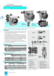
<strong>Pressure</strong> <strong>gauges</strong><br />
with spring-type mechanisms<br />
Technical description<br />
■ Application<br />
The pressure <strong>gauges</strong> are used to measure pressures above or<br />
below atmospheric (DIN 1314). The reference point for the pressure<br />
measurement is the actual atmospheric pressure at the<br />
place of installation.<br />
The SI dimension for pressure is the Pascal (Pa)<br />
1 Pa = 1 N/m 2 (DIN 1314)<br />
It has proven appropriate to use the tenth part of the Megapascal<br />
(MPa), the bar, since the bar is a pressure unit with the magnitude<br />
of the atmospheric pressure.<br />
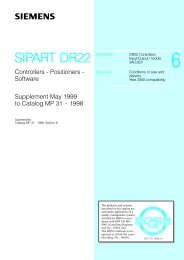
mechanism<br />
Bourdon-tube Membrane-type Capsule-type<br />
1 bar = 0.1 MPa = 0.1 N/mm 2 = 10 5 mechanism<br />
mechanism<br />
Pa<br />
Fig. 1/141 Cross-section of the spring-type mechanisms<br />
The millibar (mbar) is used for low pressures.<br />
1 mbar = 10 3 bar = 10 2 Pa<br />
The pressure <strong>gauges</strong> can be fitted with a remote transmitter for<br />
transmission of the measured values to electric indicators,<br />
<strong>Pressure</strong> <strong>gauges</strong> with a scale for other dimensions are available recorders or controllers. <strong>Pressure</strong> <strong>gauges</strong> with limit contacts<br />
as "Further designs".<br />
(electric limit transmitters) are available for triggering switching<br />
<strong>Pressure</strong> <strong>gauges</strong> with a Bourdon-tube mechanism are suitable operations when specific measured values are reached.<br />
for corrosive and non-corrosive gases, vapors and liquids.<br />
■ Design<br />
<strong>Pressure</strong> <strong>gauges</strong> with a membrane-type mechanism are suitable<br />
for corrosive and non-corrosive gases, vapors and liquids; The housings are made of CrNi steel suitable for direct mounting<br />
the designs with an open measuring flange are also suitable for at the point of measurement or for panel mounting.<br />
viscous and pulpy media.<br />
The glass panes of the pressure <strong>gauges</strong> are made of laminated<br />
<strong>Pressure</strong> <strong>gauges</strong> with a capsule-type mechanism are suitable safety glass to DIN 16 006 1 ) or flat instrument glass.<br />
for corrosive and non-corrosive gases as well as non-condensing<br />
gases.<br />
The scales for the display ranges are divided according to<br />
Circular dials correspond to DIN 16 109 1 ).<br />
<strong>Pressure</strong> <strong>gauges</strong> filled with a damping liquid for damping the DIN 16 128 1 ).<br />
indication are suitable for pulsating media and vibrating measuring<br />
points. Condensed water cannot form in them, and thus cor-<br />
coupling G½ DIN ISO 228/1 or M 20 × 1.5.<br />
The housings have a coupling to DIN 16 288 1 ): male thread of<br />
rosion of the internal components is largely inhibited.<br />
A pressure surge reducer can be connected upstream of the<br />
■ Mode of operation<br />
gauge to protect the gauge if there are pressure surges or pulsations<br />
in the medium.<br />
The pressure deforms the spring which in turn moves the coupled<br />
pointer.<br />
If temperatures below 0 °C occur, the formation of condensation<br />
must be prevented which would ice-up the mechanism and the<br />
inside of the housing. All pressure <strong>gauges</strong> are approved for temperatures<br />
of the medium up to 100 °C.<br />
Overload protection fitted in pressure <strong>gauges</strong> with spring-type mechanisms<br />
Technical description<br />
■ Application<br />
■ Technical data<br />
The overload protection only provides a safeguard against Overload<br />
short-term overload. The overload protection cannot be retrofitted!<br />
1 ) The standard will be replaced in the future by DIN EN 837 Parts 1 to 3.<br />
The product between the full-scale value<br />
and the overload protection results in the<br />
maximum pressure to which the spring can<br />
be exposed without damage.<br />
<strong>Pressure</strong> gauge Full-scale value Overload protection<br />
• With Bourdon-tube<br />
mechanism<br />
(7MD1001)<br />
• With membrane-type<br />
mechanism<br />
(7MD1101)<br />
• With capsule-type<br />
mechanism<br />
(7MD1201)<br />
ˆ 100 bar<br />
ˆ 400 bar<br />
> 400 bar<br />
All ranges<br />
2 fold<br />
1.5 fold<br />
Not increased<br />
(standard)<br />
10 fold for positive<br />
indicating ranges, but<br />
ˆ 40 bar<br />
No additional overload protection possible<br />
Siemens FI 01 · 2000 1/123
Supplementary equipment for pressure <strong>gauges</strong><br />
Remote transmitters<br />
Technical description<br />
Supplementary equipment for pressure <strong>gauges</strong><br />
■ Application<br />
<strong>Pressure</strong> <strong>gauges</strong> are equipped with remote transmitters if the<br />
measured value is not only to be indicated at the point of measurement<br />
but is to also be transmitted to another location and<br />
used e.g. for control purposes.<br />
The output signal of the remote transmitter is a load-independent<br />
direct current of 4 to 20 mA (two-wire connection) or 0 to 20 mA<br />
(three-wire connection) which is linearly proportional to the<br />
mechanical indication (rising characteristic).<br />
■ Mode of operation<br />
Bourdon-tube, membrane-type or capsule-type mechanisms<br />
are used to measure the pressure. The movement of the measuring<br />
element is used mechanically to deflect the dial, and electrically<br />
converted into an electric output signal by a sensor which<br />
measures the magnetic field. The EMC characteristics have<br />
been tested according to EN 50 081-2 and EN 50 082-2, and<br />
guarantee accurate measurement of the signal even under<br />
rough operating conditions.<br />
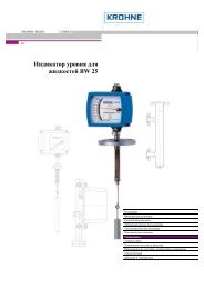
The remote transmitter has no feedback effects on the mechanical<br />
indication.<br />
Fig. 1/142 <strong>Pressure</strong> gauge with remote transmitter<br />
64<br />
22 22,5<br />
105,5<br />
■ Technical data<br />
Output<br />
Output signal S<br />
• Two-wire connection<br />
• Three-wire connection<br />
Load<br />
Accuracy<br />
Reference conditions<br />
Conformity error with<br />
• Class 1.6 for local indicator<br />
• Class 1.0 for local indicator<br />
Hysteresis with<br />
• Class 1.6 for local indicator<br />
• Class 1.0 for local indicator<br />
Response time<br />
Adjustability<br />
• Zero, electric<br />
• Span, electric<br />
Power supply effect<br />
Load effect<br />
Rated operating conditions<br />
Ambient temperature<br />
Temperature range for medium<br />
Compensated temperature range<br />
• Mean temperature coefficient<br />
- Zero<br />
- Span<br />
Degree of protection<br />
Electromagnetic compatibility<br />
(EMC)<br />
• Emitted interference<br />
• Noise immunity<br />
Electrical protection<br />
Design<br />
Dimensions (W x H x D) in mm<br />
Electrical connection<br />
Power supply<br />
Terminal voltage<br />
Permissible residual ripple<br />
4 to 20 mA<br />
0 to 20 mA<br />
R A ˆ (U H – 10 V)/0.02 A in W<br />
Fixed-point setting<br />
± 1.0 % of full-scale value<br />
± 0.8 % of full-scale value<br />
± 0.8 % of full-scale value<br />
± 0.5 % of full-scale value<br />
Approx. 50 ms<br />
± 5 % of full-scale value<br />
± 5 % of full-scale value<br />
ˆ 0.1 % of full-scale value<br />
ˆ 0.1 % of full-scale value<br />
-20 to +60 °C<br />
-25 to +100 °C<br />
-25 to +60 °C<br />
ˆ 0.3 % of full-scale value / 10 K<br />
ˆ 0.3 % of full-scale value / 10 K<br />
IP 65 to EN 60 529<br />
To EN 50 081-1, March 1993 and<br />
EN 50 081-2, March 1994<br />
To EN 50 082-2, March 1995<br />
Protected against incorrect polarity<br />
and overvoltages<br />
See Fig. 1/143<br />
Cable box, screw terminals up to<br />
2.5 mm 2<br />
DC 10 to 30 V<br />
U pp ˆ 10 %<br />
Fig. 1/143 Dimensions<br />
mA<br />
79<br />
o 99<br />
19,5<br />
Fig. 1/144 Terminal assignments for two-wire system<br />
(U H = power supply, S = output signal)<br />
mA<br />
0 V / S -<br />
UH+ / S+<br />
Test -<br />
Test +<br />
0 V / S -<br />
UH +<br />
Test +<br />
S + / Test -<br />
Fig. 1/145 Terminal assignments for three-wire system<br />
(U H = power supply, S = output signal)<br />
2<br />
1<br />
5<br />
Pg 13,5<br />
3 4<br />
Cable box<br />
2<br />
1<br />
3<br />
4<br />
5<br />
Cable box<br />
1/124 Siemens FI 01 · 2000
Supplementary equipment for pressure <strong>gauges</strong><br />
Limit contacts<br />
Technical description<br />
■ Application<br />
The limit contact activates a circuit when the measured pressure<br />
reaches a specific value. The switching point is adjustable and<br />
can be read on a limit indicator on the scale of the pressure<br />
gauge.<br />
The magnetic spring contact switches directly. It can be used if<br />
vibrations occur at the point of measurement or if there are small<br />
pulsed changes in the pressure of the measured medium. A<br />
relay must be connected if the power consumption of the consumers<br />
(e.g. horns, sirens or contactors) exceeds the switching<br />
capacity of the limit contact. The relay should be of low inductance.<br />
The inductive limit contact operates as a proximity contact. It<br />
triggers an isolating amplifier (order separately), e.g. 7NG4040,<br />
which has a sufficient switching capacity. The inductive limit<br />
contact can be used in corrosive atmospheres.<br />
■ Connections and switching functions<br />
Connections<br />
Switching functions<br />
Magnetic<br />
spring limit<br />
contact<br />
Single limit contact<br />
Inductive<br />
limit contact<br />
NO contact for rising indication<br />
corresponding to<br />
NC contact for falling indication<br />
NO contact for falling indication<br />
corresponding to<br />
NC contact for rising indication<br />
■ Design<br />
The limit contact can be set to any maximum or minimum value<br />
using a removable key. The lock is located in the window.<br />
In the case of double limit contacts, the two contacts can only be<br />
shifted together up to the smallest specified interval. Superimposed<br />
or overlapping settings are not possible!<br />
■ Mode of operation<br />
Magnetic spring limit contacts<br />
The pointer of the pressure gauge drags a contact arm which<br />
triggers the switching operation. The contact arm touches a contact<br />
pin or leaves it when the measured value exceeds or falls<br />
below the set limit. A small permanent magnet is located next to<br />
the contact pin. This accelerates the switch-on procedure<br />
shortly before the limit is reached, increases the contact pressure,<br />
and slightly delays the switch-off procedure so that the<br />
contacts are separated suddenly.<br />
Inductive limit contacts<br />
The pointer of the pressure gauge moves a metal control lug<br />
which influences the high-frequency magnetic field of a pair of<br />
coils. This field is generated by an oscillator. Once the limit has<br />
been reached, the control lug enters the stray field of the pair of<br />
coils. The oscillation amplitude is then reduced. An electronic<br />
amplifier coupled to the oscillator then controls a transistor in the<br />
input circuit of the separate isolating amplifier, e.g. 7NG4040.<br />
The transistor triggers the actual switching procedure.<br />
■ Technical data<br />
Magnetic spring limit contacts 1 or 2<br />
Smallest interval<br />
between double contacts 4 % of indicating span<br />
Switching capacity<br />
Max. 30 W / 50 VA (non-filled indicators)<br />
Max. 20 W / 20 VA (filled indicators)<br />
Min. 0.25 W / 0.25 VA<br />
Loading capacity<br />
Max. 1 A, min. 20 mA<br />
Voltage<br />
Max. AC/DC 230 V, min. AC/DC 24 V<br />
Contact material<br />
Ag80 Ni20<br />
Electrical connection<br />
Cable box with Pg 13.5 screwed<br />
gland, terminals for max. 2.5 mm 2<br />
conductors<br />
Inductive limit contacts 1 or 2<br />
Further data depend on the isolating amplifier, e.g. 7NG4040.<br />
Double limit contacts<br />
Limit contact I:<br />
NO contact for rising indication<br />
corresponding to<br />
NC contact for falling indication<br />
Limit contact II:<br />
NO contact for rising indication<br />
corresponding to<br />
NC contact for falling indication<br />
Limit contact I:<br />
NO contact for falling indication<br />
corresponding to<br />
NC contact for rising indication<br />
Limit contact II:<br />
NO contact for rising indication<br />
corresponding to<br />
NC contact for falling indication<br />
Limit contact I:<br />
NO contact for falling indication<br />
corresponding to<br />
NC contact for rising indication<br />
Limit contact II<br />
NO contact for falling indication<br />
corresponding to<br />
NC contact for rising indication<br />
Limit contact I:<br />
NO contact for rising indication<br />
corresponding to<br />
NC contact for falling indication<br />
Limit contact II:<br />
NO contact for falling indication<br />
corresponding to<br />
NC contact for rising indication<br />
With an increasing indication, limit contact I always switches first, with a<br />
falling indication limit contact II. The sequence cannot be reversed (no<br />
overlapping of contacts).<br />
Contact designations:<br />
NO contact (also make contact)<br />
The contact closes a previously open circuit either with a rising or<br />
falling indication.<br />
NC contact (also break contact)<br />
The contact opens a previously closed circuit either with a rising or<br />
falling indication.<br />
Rising indication<br />
Clockwise pointer deflection.<br />
Falling indication<br />
Counterclockwise pointer deflection.<br />
Siemens FI 01 · 2000 1/125
<strong>Pressure</strong> <strong>gauges</strong><br />
with Bourdon-tube mechanism<br />
7MD1001<br />
<strong>Pressure</strong> <strong>gauges</strong><br />
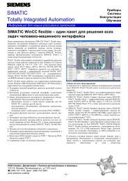
<strong>Pressure</strong> gauge with two limit contacts<br />
<strong>Pressure</strong> gauge with remote transmitter<br />
Fig. 1/146 <strong>Pressure</strong> <strong>gauges</strong> with Bourdon-tube mechanism for direct<br />
mounting<br />
■ Application<br />
The pressure <strong>gauges</strong> are suitable for corrosive and non-corrosive<br />
gases, vapors and liquids.<br />
■ Technical data<br />
Input<br />
Measured variable<br />
<strong>Pressure</strong><br />
Measuring range<br />
• Span<br />
0.6 to 1000 bar<br />
Accuracy<br />
Error limits Class 1.0 to DIN 16 005<br />
Rated operating conditions<br />
Installation conditions<br />
Mounting position<br />
Scale vertical<br />
Ambient conditions<br />
Ambient temperature<br />
Temperature of medium<br />
Degree of protection to<br />
EN 60 529<br />
Conditions of medium<br />
<strong>Pressure</strong> limit<br />
• Steady load<br />
• Alternating load<br />
• Short-term overload<br />
Design<br />
Approx. weight in kg<br />
• Without supplementary equipment<br />
• With limit signal transmitter<br />
• With remote transmitter<br />
-20 to +60 °C<br />
At temperatures below 0 °C, prevent<br />
condensation from being formed and<br />
icing-up the measuring spring and the<br />
inside of the housing<br />
ˆ 200 °C, (ˆ 100 °C with damping<br />
liquids)<br />
IP 54; IP 65 with damping liquid<br />
100 % of full-scale value<br />
90 % of full-scale value<br />
1.3 times the span<br />
Without damping<br />
liquid<br />
0.65<br />
0.9<br />
0.95<br />
With damping<br />
liquid<br />
0.9<br />
1.2<br />
1.2<br />
Dimensions (W x H x D) See Figs. 1/147 to 1/150<br />
Design<br />
(continued)<br />
Material<br />
• Wetted parts materials<br />
- Coupling<br />
• Non-wetted parts materials<br />
- Bourdon tube<br />
- Front pane<br />
- Housing<br />
- Pointer mechanism<br />
Electrical connection<br />
Safety design<br />
Supplementary equipment<br />
Indicator<br />
Range<br />
Scale<br />
Pointer deflection<br />
Stainless steel, mat. No. 1.4571, with<br />
thread G½ DIN ISO 228/1 or M20 x<br />
1.5; washer DIN 16 258 is suitable<br />
Stainless steel, mat. No. 1.4571<br />
Multi-layer safety glass<br />
Stainless steel, mat. No. 1.4301, bright<br />
drawn; optionally filled with damping<br />
liquid; unbreakable partition between<br />
Bourdon tube and dial; rear panel with<br />
pressure release outlet<br />
Made of CrNi steel<br />
Cable box with Pg 13.5 screwed<br />
gland, terminals for max. 2.5 mm 2<br />
conductors<br />
To DIN 16 006<br />
See pages 1/124 and 1/125<br />
According to Ordering data<br />
Circular<br />
0 to 270°<br />
1/126 Siemens FI 01 · 2000
<strong>Pressure</strong> <strong>gauges</strong><br />
with Bourdon-tube mechanism<br />
7MD1001<br />
101<br />
59,5<br />
101<br />
94<br />
98<br />
55<br />
55,2<br />
2<br />
31<br />
3<br />
SW 22<br />
1<br />
87<br />
25 2<br />
87<br />
1<br />
SW 22<br />
Pg 13,5<br />
74<br />
23<br />
20<br />
1 Coupling G½ or M20 x 1.5 2 Bayonet ring<br />
Fig. 1/147 <strong>Pressure</strong> for direct mounting without supplementary equipment,<br />
dimensions<br />
98<br />
101<br />
105,5<br />
1 Coupling G½ or M20 x 1.5<br />
2 Cable box or plug for electric connections<br />
3 Removable key for limit contacts<br />
Fig. 1/149 <strong>Pressure</strong> gauge for direct mounting, with limit contacts,<br />
dimensions<br />
116<br />
59<br />
8,9<br />
63<br />
87<br />
SW 22 1<br />
1 Coupling G½ or M20 x 1.5<br />
2 Cable box or plug for electric connections<br />
2<br />
Pg 13,5<br />
M4<br />
1<br />
SW 22<br />
87<br />
1 Coupling G½ or M20 x 1.5<br />
23<br />
3<br />
o 132<br />
Fig. 1/148 <strong>Pressure</strong> gauge for direct mounting, with remote transmitter,<br />
dimensions<br />
Fig. 1/150 <strong>Pressure</strong> gauge for panel mounting, without supplementary<br />
equipment, dimensions<br />
(see Figs. 1/148 and 1/149 for dimensions of supplementary equipment)<br />
Siemens FI 01 · 2000 1/127
7MD1001<br />
<strong>Pressure</strong> <strong>gauges</strong><br />
with Bourdon-tube mechanism<br />
■ Ordering data<br />
.<br />
<strong>Pressure</strong> gauge<br />
with Bourdon-tube mechanism<br />
Safety design<br />
to DIN 16 006<br />
Direct mounting<br />
Panel mounting<br />
Supplementary electric<br />
equipment<br />
Damping<br />
liquid<br />
None<br />
Without<br />
With<br />
Remote transmitter<br />
Power supply Characteristic<br />
Two-wire system<br />
DC<br />
Rising<br />
10 to 30 V<br />
Three-wire system<br />
DC<br />
Rising<br />
10 to 30 V<br />
Inductive limit contacts<br />
1 limit contact<br />
NO contact for<br />
rising indication<br />
NO contact for<br />
falling indication<br />
2 limit contacts<br />
NO contact I<br />
for indication<br />
NO contact II<br />
for indication<br />
Without<br />
With<br />
Without<br />
With<br />
Without<br />
With<br />
Without<br />
With<br />
Rising Rising Without<br />
With<br />
Falling Rising Without<br />
With<br />
Falling Falling Without<br />
With<br />
Rising Falling Without<br />
With<br />
Magnetic spring limit contacts<br />
1 limit contact<br />
NO contact for<br />
rising indication<br />
NO contact for<br />
falling indication<br />
2 limit contacts<br />
NO contact I<br />
for indication<br />
NO contact II<br />
for indication<br />
Without<br />
With<br />
Without<br />
With<br />
Rising Rising Without<br />
With<br />
Falling Rising Without<br />
With<br />
Falling Falling Without<br />
With<br />
Rising Falling Without<br />
With<br />
<strong>Pressure</strong> connection:thread G½<br />
M20 x 1.5<br />
Order No.<br />
7MD1001-<br />
77777- 7 777<br />
1<br />
2<br />
A 0 0 0<br />
A 0 0 1<br />
B 0 0 0<br />
B 0 0 2<br />
C 0 0 0<br />
C 0 0 2<br />
D 1 1 0<br />
D 1 1 2<br />
D 1 2 0<br />
D 1 2 2<br />
E 2 1 0<br />
E 2 1 2<br />
E 2 2 0<br />
E 2 2 2<br />
E 2 3 0<br />
E 2 3 2<br />
E 2 4 0<br />
E 2 4 2<br />
F 1 1 0<br />
F 1 1 2<br />
F 1 2 0<br />
F 1 2 2<br />
G 2 1 0<br />
G 2 1 2<br />
G 2 2 0<br />
G 2 2 2<br />
G 2 3 0<br />
G 2 3 2<br />
G 2 4 0<br />
G 2 4 2<br />
A<br />
B<br />
■ Ordering data<br />
Further designs<br />
(Please add "-Z" to Order No.)<br />
Degreased mechanism:<br />
for measuring oxygen<br />
Overload protection fitted<br />
(description on page 1/123)<br />
Report with listing of individual measured<br />
values; 5 points/gauge<br />
Order Plain text<br />
code<br />
A03 –<br />
A21 –<br />
A24 –<br />
Plug connector instead of cable box;<br />
degree of protection EN 60 529/IEC 529 –<br />
IP 65; approved for AC 250 V;<br />
conductor cross-section up to 2.5 mm 2 A06 –<br />
Red mark on the scale to identify a<br />
particular value<br />
Additional scale inscription,<br />
e.g. "Steam" or "Boiler 1"<br />
Other indicating range:<br />
dimension other than bar or mbar or/and<br />
numbers other than those in the Ordering<br />
data (non-official units such as kp/cm 2 or<br />
mm water gauge are only available on<br />
export models)<br />
Non-linear scale graduation, e.g. quadratic<br />
or calculated according to information<br />
from customer. Start-of-scale and<br />
full-scale values must correspond with<br />
those of a listed indicating range in the<br />
Ordering data<br />
Y03<br />
Y04<br />
Y05<br />
Y06<br />
Other special scales and colored scale sections on request.<br />
Order codes additive, any sequence.<br />
Red mark at<br />
... bar<br />
Scale<br />
inscription: ...<br />
Indicating<br />
range:<br />
... to ... ...<br />
Scale<br />
graduation: ...<br />
Additional second scale Y07 2nd scale<br />
... to ... ...<br />
Identification on housing<br />
Plastic foil labelled;<br />
e.g. "Measuring point P100"<br />
Span<br />
bar<br />
0.6<br />
1<br />
1.6<br />
2.5<br />
4<br />
6<br />
10<br />
16<br />
25<br />
40<br />
60<br />
100<br />
160<br />
250<br />
400<br />
600<br />
1000<br />
1<br />
1.6<br />
2.5<br />
4<br />
6<br />
10<br />
16<br />
Indicating range<br />
bar<br />
0 to 0.6<br />
0 to 1<br />
0 to 1.6<br />
0 to 2.5<br />
0 to 4<br />
0 to 6<br />
0 to 10<br />
0 to 16<br />
0 to 25<br />
0 to 40<br />
0 to 60<br />
0 to 100<br />
0 to 160<br />
0 to 250<br />
0 to 400<br />
0 to 600<br />
0 to 1000<br />
-1 to +0<br />
-1 to +0.6<br />
-1 to +1.5<br />
-1 to +3<br />
-1 to +5<br />
-1 to +9<br />
-1 to +15<br />
1 A A<br />
1 B A<br />
1 C A<br />
1 D A<br />
1 E A<br />
1 F A<br />
1 G A<br />
1 H A<br />
1 J A<br />
1 K A<br />
1 L A<br />
2 A A<br />
2 B A<br />
2 C A<br />
2 D A<br />
2 E A<br />
3 A A<br />
4 A A<br />
4 B A<br />
4 C A<br />
4 D A<br />
4 E A<br />
4 F A<br />
4 G A<br />
Y08<br />
Housing<br />
identification: ...<br />
1/128<br />
Siemens FI 01 · 2000
<strong>Pressure</strong> <strong>gauges</strong><br />
with membrane-type mechanism<br />
7MD1101<br />
<strong>Pressure</strong> gauge with two limit contacts<br />
<strong>Pressure</strong> gauge with remote transmitter<br />
Fig. 1/151 <strong>Pressure</strong> <strong>gauges</strong> with membrane mechanism for direct mounting<br />
■ Application<br />
The pressure <strong>gauges</strong> are suitable for corrosive and non-corrosive<br />
gases, vapors and liquids; designs with a measuring flange<br />
open at the bottom are also suitable for viscous and pulpy media.<br />
■ Technical data<br />
Input<br />
Measured variable<br />
Measuring range<br />
• Span<br />
Accuracy<br />
Error limits<br />
• Membrane without Teflon coating<br />
• Membrane with Teflon coating<br />
Rated operating conditions<br />
Installation conditions<br />
Mounting position<br />
Ambient conditions<br />
Ambient temperature<br />
Temperature of medium<br />
Degree of prot. to EN 60 529<br />
• Without damping liquid<br />
• With damping liquid<br />
Conditions of medium<br />
<strong>Pressure</strong> limit<br />
• Steady load<br />
• Alternating load<br />
• Short-term overload<br />
- ˆ 0.25 bar and > 2.5 bar<br />
- > 0.25 bar and ˆ 2.5 bar<br />
Design<br />
Approx. weight in kg<br />
• Basic pressure gauge<br />
• Damping liquid<br />
• Limit signal transmitter<br />
• Remote transmitter<br />
Approx. additional weight in kg<br />
with open lower part of flange<br />
• DN 25/DN 50<br />
• Di 64/Di 122<br />
• DN 125<br />
<strong>Pressure</strong><br />
16 mbar to 40 bar<br />
To DIN 16 005<br />
Class 1.6<br />
Class 2.0<br />
Scale vertical<br />
-20 to +60 °C<br />
At temperatures below 0 °C, prevent<br />
condensation from being formed and<br />
icing-up the measuring spring and the<br />
inside of the housing<br />
ˆ 100 °C<br />
IP 54<br />
IP 65<br />
100 % of full-scale value<br />
90 % of full-scale value<br />
500 % of full-scale value<br />
300 % of full-scale value,<br />
500 % of full-scale value with upper<br />
part of measuring flange made of CrNi<br />
steel, but ˆ 40 bar<br />
Upper part of measuring flange<br />
100 mm diam. 160 mm diam.<br />
1.4<br />
0.4<br />
0.3<br />
0.3<br />
0.9/2.5<br />
0/-<br />
-<br />
2.6<br />
0.4<br />
0.3<br />
0.3<br />
3/3<br />
-/0<br />
3.9<br />
Dimensions (W x H x D) in mm See Figs. 1/152 to 1/154<br />
Design<br />
Material<br />
• Wetted parts materials<br />
- Coupling for closed measuring<br />
flange<br />
• Non-wetted parts materials<br />
- Membrane<br />
With upper part of<br />
measuring flange: steel<br />
ˆ 2.5 bar<br />
> 2.5 bar<br />
With upper part of measuring<br />
flange: CrNi steel<br />
ˆ 250 mbar<br />
> 250 mbar<br />
- Upper part of measuring<br />
flange<br />
- Bottom part of measuring<br />
flange<br />
- Front pane<br />
Upper part of flange: steel Flat instrument glass<br />
Upper part of flange:<br />
NiCr steel<br />
Multi-layer safety glass<br />
- Housing<br />
CrNi steel, mat. No. 1.4301, bright<br />
drawn; optionally filled with damping<br />
liquid; with upper part of flange made<br />
of CrNi steel: additional rear panel with<br />
pressure release outlet<br />
- Pointer mechanism<br />
Upper part of flange: steel Cu alloy<br />
Upper part of flange:<br />
NiCr steel<br />
CrNi steel<br />
Electrical connection<br />
Cable box with Pg 13.5 screwed<br />
gland, terminals for max. 2.5 mm 2<br />
conductors<br />
Safety design<br />
Supplementary equipment<br />
Indicator<br />
Range<br />
Scale<br />
Pointer deflection<br />
(continued)<br />
Steel, mat. No. 1.0330, or NiCr steel,<br />
mat. No. 1.4571, with thread G½<br />
DIN ISO 228/1 or M20 x 1.5;<br />
washer DIN 16 258 is suitable<br />
Without/with PTFE coating, horizontal<br />
CrNi steel, mat. No. 1.4571<br />
CrNi steel, mat. No. 1.4568<br />
CrNi steel, mat. No. 1.4571<br />
NiCrCo alloy (Duratherm)<br />
Steel, mat. No. 1.0330, black enamelled<br />
or CrNi steel, mat. No. 1.4301<br />
Steel, mat. No. 1.0330, black enamelled<br />
or CrNi steel, mat. No. 1.4571<br />
To DIN 16 006<br />
See pages 1/124 and 1/125<br />
According to Ordering data<br />
Circular<br />
0 to 270°<br />
Siemens FI 01 · 2000 1/129
7MD1101<br />
<strong>Pressure</strong> <strong>gauges</strong><br />
with membrane-type mechanism<br />
■ Ordering data Order No. Order No.<br />
.<br />
<strong>Pressure</strong> gauge<br />
with membrane-type mechanism<br />
Upper part of meas. flange<br />
160 mm diameter<br />
Upper part of meas. flange<br />
100 mm diameter<br />
Direct mounting<br />
Upper part of measuring flange made of steel,<br />
black enamelled<br />
Possible spans 16 1 )/25/40/<br />
60/100/160/250 mbar<br />
Possible spans 0.4/0.6/1/1.6/<br />
2.5/4/6/16/25/40 bar<br />
7MD1101-<br />
77777- 7 777<br />
7MD1101-<br />
77777- 7 777<br />
Membrane Uncoated<br />
With PTFE coating<br />
Supplementary<br />
Damping<br />
electric equipment<br />
liquid<br />
None<br />
Without<br />
With<br />
Remote transmitter<br />
Power supply Characteristic<br />
Two-wire system<br />
DC<br />
Rising<br />
10 to 30 V<br />
Three-wire system<br />
DC<br />
Rising<br />
10 to 30 V<br />
Inductive limit contacts<br />
1 limit contact<br />
NO contact for<br />
rising indication<br />
NO contact for<br />
falling indication<br />
2 limit contacts<br />
NO contact I<br />
for indication<br />
NO contact II<br />
for indication<br />
Without<br />
With<br />
Without<br />
With<br />
Without<br />
With<br />
Without<br />
With<br />
Rising Rising Without<br />
With<br />
Falling Rising Without<br />
With<br />
Falling Falling Without<br />
With<br />
Rising Falling Without<br />
With<br />
Magnetic spring limit contacts<br />
1 limit contact<br />
NO contact for<br />
Without<br />
rising indication<br />
With<br />
NO contact for<br />
Without<br />
falling indication<br />
With<br />
2 limit contacts<br />
NO contact I<br />
for indication<br />
NO contact II<br />
for indication<br />
Rising Rising Without<br />
With<br />
Falling Rising Without<br />
With<br />
Falling Falling Without<br />
With<br />
Rising Falling Without<br />
With<br />
Flange lower part (see Figs. 1/154 to 1/156)<br />
Material Form <strong>Pressure</strong><br />
connection<br />
Steel, Closed G½<br />
black<br />
M20 x 1.5<br />
enamelled<br />
CrNi<br />
steel<br />
Outer<br />
diameter<br />
Open Sealing face 160 mm<br />
160 mm<br />
240 mm<br />
Closed<br />
G½<br />
M20 x 1.5<br />
DN/<br />
Di<br />
160 mm –<br />
160 mm –<br />
25<br />
122<br />
125<br />
160 mm –<br />
160 mm –<br />
25<br />
122<br />
125<br />
Open Sealing face 160 mm<br />
160 mm<br />
240 mm<br />
1) Not with designs with limit contact<br />
0<br />
1<br />
A 0 0 0<br />
A 0 0 1<br />
B 0 0 0<br />
B 0 0 2<br />
C 0 0 0<br />
C 0 0 2<br />
D 1 1 0<br />
D 1 1 2<br />
D 1 2 0<br />
D 1 2 2<br />
E 2 1 0<br />
E 2 1 2<br />
E 2 2 0<br />
E 2 2 2<br />
E 2 3 0<br />
E 2 3 2<br />
E 2 4 0<br />
E 2 4 2<br />
F 1 1 0<br />
F 1 1 2<br />
F 1 2 0<br />
F 1 2 2<br />
G 2 1 0<br />
G 2 1 2<br />
G 2 2 0<br />
G 2 2 2<br />
G 2 3 0<br />
G 2 3 2<br />
G 2 4 0<br />
G 2 4 2<br />
L<br />
M<br />
N<br />
P<br />
Q<br />
R<br />
S<br />
T<br />
U<br />
V<br />
Outer<br />
diam.<br />
100 mm<br />
100 mm<br />
100 mm<br />
115 mm<br />
165 mm<br />
100 mm<br />
100 mm<br />
100 mm<br />
115 mm<br />
165 mm<br />
2<br />
3<br />
A 0 0 0<br />
A 0 0 1<br />
B 0 0 0<br />
B 0 0 2<br />
C 0 0 0<br />
C 0 0 2<br />
D 1 1 0<br />
D 1 1 2<br />
D 1 2 0<br />
D 1 2 2<br />
E 2 1 0<br />
E 2 1 2<br />
E 2 2 0<br />
E 2 2 2<br />
E 2 3 0<br />
E 2 3 2<br />
E 2 4 0<br />
E 2 4 2<br />
G 2 1 0<br />
G 2 1 2<br />
G 2 2 0<br />
G 2 2 2<br />
G 2 3 0<br />
G 2 3 2<br />
G 2 4 0<br />
G 2 4 2<br />
DN/<br />
Di<br />
–<br />
–<br />
64<br />
25<br />
50<br />
–<br />
–<br />
64<br />
25<br />
50<br />
A<br />
B<br />
C<br />
D<br />
E<br />
F<br />
G<br />
H<br />
J<br />
K<br />
Span<br />
bar<br />
Span<br />
F 1 1 0 bar<br />
F 1 1 2<br />
F 1 2 0<br />
F 1 2 2<br />
Indicating range<br />
bar<br />
0.4 0 to + 0.4<br />
-0.4 to 0<br />
- 0.25 to + 0.15<br />
- 0.15 to + 0.25<br />
0.6 0 to + 0.6<br />
-0.6 to 0<br />
- 0.4 to + 0.2<br />
- 0.2 to + 0.4<br />
1 0 to + 1<br />
-1 to 0<br />
- 0.6 to + 0.4<br />
- 0.4 to + 0.6<br />
1.6 0 to + 1.6<br />
-1 to 0.6<br />
2.5 0 to + 2.5<br />
- 1 to + 1.5<br />
4 0 to + 4<br />
-1 to + 3<br />
6 0 to + 6<br />
-1 to + 5<br />
10 0 to + 10<br />
-1 to + 9<br />
16 0 to + 16<br />
-1 to + 15<br />
2 J A<br />
2 K A<br />
2 L A<br />
2 M A<br />
2 N A<br />
2 P A<br />
2 Q A<br />
2 R A<br />
2 S A<br />
2 T A<br />
2 U A<br />
2 V A<br />
3 A A<br />
3 B A<br />
3 C A<br />
3 D A<br />
3 E A<br />
3 F A<br />
3 G A<br />
3 H A<br />
3 J A<br />
3 K A<br />
3 L A<br />
3 M A<br />
25 0 to + 25 3 N A<br />
40 0 to + 40 3 P A<br />
Indicating range<br />
bar<br />
16 0 to +16<br />
-16 to 0<br />
-10 to +6<br />
-6 to +10<br />
25 0 to +25<br />
-25 to 0<br />
-15 to +10<br />
-10 to +15<br />
40 0 to +40<br />
-40 to 0<br />
-25 to +15<br />
-15 to +25<br />
60 0 to +60<br />
-60 to 0<br />
-40 to +20<br />
-20 to +40<br />
100 0 to +100<br />
-100 to 0<br />
-60 to +40<br />
-40 to +60<br />
160 0 to +160<br />
-160 to 0<br />
-100 to +60<br />
-60 to +100<br />
250 0 to +250<br />
-250 to 0<br />
-150 to +100<br />
-100 to +150<br />
1 A B<br />
1 B B<br />
1 C B<br />
1 D B<br />
1 E B<br />
1 F B<br />
1 G B<br />
1 H B<br />
1 J B<br />
1 K B<br />
1 L B<br />
1 M B<br />
1 N B<br />
1 P B<br />
1 Q B<br />
1 R B<br />
1 S B<br />
1 T B<br />
1 U B<br />
1 V B<br />
2 A B<br />
2 B B<br />
2 C B<br />
2 D B<br />
2 E B<br />
2 F B<br />
2 G B<br />
2 H B<br />
1/130<br />
Siemens FI 01 · 2000
<strong>Pressure</strong> <strong>gauges</strong><br />
with membrane-type mechanism<br />
7MD1101<br />
■ Ordering data<br />
Further designs<br />
(please add "-Z" to Order No.)<br />
Upper part of measuring flange<br />
X 5 CrNi 18 9, mat. No. 1.4301;<br />
safety design<br />
Order Plain text<br />
code<br />
B01 –<br />
Overload protection fitted<br />
A21 –<br />
(description on page 1/123)<br />
Report with listing of individual measured A24 –<br />
values; 5 points/gauge<br />
Plug connector instead of cable box;<br />
degree of protection EN 60 529/IEC 529 –<br />
IP 65; approved for AC 250 V;<br />
conductor cross-section up to 2.5 mm 2 A06 –<br />
Red mark on the scale to identify a particular<br />
value<br />
Additional scale inscription,<br />
e.g. "Steam" or "Boiler 1"<br />
Other indicating range:<br />
dimension other than bar or mbar or/and<br />
numbers other than those in the Ordering<br />
data (non-official units such as kp/cm 2 or<br />
mm water gauge are only available on<br />
export models)<br />
Non-linear scale graduation, e.g. quadratic<br />
or calculated according to information<br />
from customer. Start-of-scale and<br />
full-scale values must correspond with<br />
those of a listed indicating range in the<br />
Ordering data<br />
Y03<br />
Y04<br />
Y05<br />
Y06<br />
Other special scales and colored scale sections on request.<br />
Order codes additive, any sequence.<br />
Red mark at<br />
... bar or<br />
... mbar<br />
Scale inscription:<br />
...<br />
Indicating<br />
range:<br />
... to ... ...<br />
Scale graduation:<br />
...<br />
Additional second scale Y07 2nd scale<br />
... to ... ...<br />
Identification on housing<br />
Plastic foil labelled;<br />
e.g. "Measuring point P100"<br />
Y08<br />
Housing<br />
identification: ...<br />
o a<br />
101 49,5<br />
118<br />
15,5<br />
SW 22 1<br />
1 Coupling,<br />
G½ or M20 x 1.5<br />
« a Span Gauge 7MD1101- 2 Upper part of<br />
mm min. max. -7 7 7 7 7 - .... measuring flange<br />
bar bar<br />
3 Lower part of<br />
measuring flange<br />
100 0.4 40 A, B, F, G<br />
160 0.16 0.25 L, M, R, S<br />
Fig. 1/152 <strong>Pressure</strong> gauge without supplementary equipment, measuring<br />
flange closed; dimensions<br />
33,5<br />
1<br />
113 101<br />
SW 27<br />
Pg 13,5<br />
118<br />
o a<br />
« a as in Fig. 1/152<br />
1 Coupling, G½ or M20 x 1.5<br />
2 Cable box or plug for electric connections<br />
2<br />
2<br />
3<br />
105,5<br />
Fig. 1/153 <strong>Pressure</strong> gauge with remote transmitter, measuring flange<br />
closed; dimensions<br />
101 87,5<br />
94<br />
2 3<br />
15,5<br />
Pg 13,5<br />
118<br />
SW 22 1<br />
« a Span Gauge 7MD1101-<br />
mm min. max. -7 7 7 7 7 - ....<br />
bar<br />
100 0.4 bar 40 A, B, F, G<br />
160 25 mbar 0.25 L, M, R, S<br />
o a<br />
1 Coupling,<br />
G½ or M20 x 1.5<br />
2 Cable box or plug<br />
for electric<br />
connections<br />
3 Removable key<br />
for limit contacts<br />
Fig. 1/154 <strong>Pressure</strong> gauge with limit contacts, measuring flange closed;<br />
dimensions<br />
Siemens FI 01 · 2000 1/131
<strong>Pressure</strong> <strong>gauges</strong><br />
with membrane-type mechanism<br />
7MD1101<br />
<strong>Pressure</strong> <strong>gauges</strong><br />
A<br />
B<br />
A<br />
B<br />
n x M8<br />
H<br />
n x o 18<br />
o D0<br />
H<br />
112<br />
101<br />
10<br />
o Di<br />
20<br />
b<br />
36<br />
2<br />
25<br />
2<br />
A<br />
o Lk<br />
o D<br />
o DN<br />
o d1<br />
o Lk<br />
o D<br />
D Lk Di No. of H Span Gauge 7MD1101-<br />
mm mm mm holes mm min. max. -7 7 7 7 7 - ....<br />
3<br />
4x<br />
M12<br />
o25<br />
(DN)<br />
o 68<br />
o 85<br />
o 160<br />
4x<br />
M12<br />
o25<br />
(DN)<br />
o 68<br />
o 85<br />
o 115<br />
100 83 64 6 97 0.4 bar 40 bar C, H<br />
160 140 122 10 128 16 mbar 0.25 bar P, U<br />
B<br />
Measuring flange Span Gauge<br />
Upper Lower part<br />
part No. of min. max. 7MD1101-<br />
D O D Lk d 1 DN b H holes -7 7 7 7 7 -...<br />
mm mm mm mm mm mm n bar bar .<br />
100 165 125 102 50 26.5 100 4 0.4 40 E, K<br />
160 240 200 178 125 18 95 8 0.16 25 Q, V<br />
All other dimensions correspond to those of the pressure <strong>gauges</strong> with a<br />
closed measuring flange (Figs. 1/152 to 1/154)<br />
Fig. 1/155 <strong>Pressure</strong> gauge with measuring flange open at bottom;<br />
dimensions<br />
(A: upper and lower parts with same external diameter;<br />
B: external diameter of lower part greater than that of upper part;<br />
mating flange to DIN 2501, sealing face form D to DIN 2526; DN 50/PN 40<br />
and DN 125/PN 6)<br />
DN Span Gauge 7MD1101-<br />
min. max. -7 7 7 7 7 - ....<br />
A 25 16 mbar 250 mbar N, T<br />
B 25 0.4 bar 40 bar D, J<br />
All other dimensions correspond to those of the pressure <strong>gauges</strong> with a<br />
closed measuring flange (Figs. 1/152 to 1/154)<br />
Fig. 1/156 <strong>Pressure</strong> gauge with measuring flange open at bottom for<br />
DN 25/PN 40; dimensions (mating flange to DIN 2501, sealing face form<br />
D to DIN 2516)<br />
1/132 Siemens FI 01 · 2000
<strong>Pressure</strong> <strong>gauges</strong><br />
with capsule-type mechanism<br />
7MD1201<br />
<strong>Pressure</strong> gauge with two limit contacts<br />
<strong>Pressure</strong> gauge with remote transmitter<br />
Fig. 1/157 <strong>Pressure</strong> <strong>gauges</strong> with capsule-type mechanism for direct<br />
mounting<br />
■ Application<br />
The pressure <strong>gauges</strong> are suitable for corrosive, non-condensing<br />
gases (not for vapors and liquids).<br />
49,5<br />
15,5<br />
■ Technical data<br />
Input<br />
Measured variable<br />
<strong>Pressure</strong><br />
Measuring range<br />
• Span<br />
0.6 to 100 mbar<br />
Accuracy<br />
Error limits Class 1.0 to DIN 16 005<br />
Rated operating conditions<br />
Installation conditions<br />
Mounting position<br />
Scale vertical<br />
Ambient conditions<br />
Ambient temperature<br />
Temperature of medium<br />
Degree of prot. to EN 60 529<br />
Conditions of medium<br />
<strong>Pressure</strong> limit<br />
• Steady load<br />
• Alternating load<br />
• Short-term overload<br />
Design<br />
Approx. weight in kg<br />
• Without supplementary equipment<br />
• With limit signal transmitter<br />
• With remote transmitter<br />
Dimensions (W x H x D) in mm<br />
Material<br />
• Wetted parts materials<br />
-Coupling<br />
• Non-wetted parts materials<br />
- Capsule element<br />
- Front pane<br />
- Housing<br />
- Pointer mechanism<br />
Electrical connection<br />
Safety design<br />
Supplementary equipment<br />
Indicator<br />
Range<br />
Scale<br />
Pointer deflection<br />
-20 to +60 °C<br />
At temperatures below 0 °C, prevent<br />
condensation from being formed and<br />
icing-up the measuring spring and the<br />
inside of the housing<br />
ˆ 100 °C<br />
IP 54<br />
100 % of full-scale value<br />
90 % of full-scale value<br />
5000 % of full-scale value<br />
1.6<br />
1.8<br />
1.9<br />
See Figs. 1/158 to 1/160<br />
CrNi steel, mat. No. 1.4571, with<br />
thread G½ DIN ISO 228/1 or M20 x<br />
1.5; washer DIN 16 258 is suitable<br />
CrNi steel, mat. No. 1.4571,<br />
horizontally arranged<br />
Multi-layer safety glass<br />
CrNi steel, bright drawn; rear panel<br />
with pressure release outlet<br />
Made of CrNi steel<br />
Cable box with Pg 13.5 screwed<br />
gland, terminals for max. 2.5 mm 2<br />
To DIN 16 006<br />
See pages 1/124 and 1/125<br />
According to Ordering data<br />
Circular<br />
0 to 270°<br />
1 Coupling<br />
G½ or<br />
M20 x 1.5<br />
Fig. 1/158 <strong>Pressure</strong> gauge without supplementary equipment, dimensions<br />
34<br />
113<br />
101<br />
Fig. 1/159 <strong>Pressure</strong> gauge with remote transmitter, dimensions<br />
Fig. 1/160 <strong>Pressure</strong> gauge with limit contacts, dimensions<br />
175<br />
175<br />
101<br />
1 Coupling<br />
G½ or<br />
M20 x 1.5<br />
2 Cable box or plug for electrical connections<br />
3<br />
88<br />
15,5<br />
175<br />
1 Coupling<br />
G½ or<br />
M20 x 1.5<br />
2 Cable box or plug for electrical connections<br />
3 Removable key for limit contacts<br />
1<br />
1<br />
o 133<br />
101<br />
1<br />
o 133<br />
o 133<br />
SW 22<br />
SW 22<br />
105,5<br />
2<br />
SW 22<br />
Pg 13,5<br />
94<br />
2<br />
Pg 13,5<br />
Siemens FI 01 · 2000 1/133
7MD1201<br />
<strong>Pressure</strong> <strong>gauges</strong><br />
with capsule-type mechanism<br />
■ Ordering data<br />
Order No.<br />
.<br />
Press. gauge with capsule-type mechanism 7MD1201-<br />
Safety design, direct mounting 2 7777- 7 7 A 0<br />
Supplementary electric equipment<br />
None A 0 0<br />
Remote transmitter<br />
Power supply Charact.<br />
Two-wire DC 10 ... 30 V Rising B 0 0<br />
system<br />
Three-wire DC 10 ... 30 V Rising C 0 0<br />
system<br />
Inductive limit contacts<br />
1 limit contact<br />
NO contact for rising indication<br />
D 1 1<br />
NO contact for falling indication<br />
D 1 2<br />
2 limit contacts<br />
NO contact I<br />
for indication<br />
NO contact II<br />
for indication<br />
Rising Rising E 2 1<br />
Falling Rising E 2 2<br />
Falling Falling E 2 3<br />
Rising Falling E 2 4<br />
Magnetic spring limit contacts<br />
1 limit contact<br />
NO contact for rising indication<br />
NO contact for falling indication<br />
2 limit contacts<br />
NO contact I<br />
for indication<br />
NO contact II<br />
for indication<br />
F 1 1<br />
F 1 2<br />
Rising Rising G 2 1<br />
Falling Rising G 2 2<br />
Falling Falling G 2 3<br />
Rising Falling G 2 4<br />
<strong>Pressure</strong> connection: thread G½<br />
M20 x 1.5<br />
A<br />
B<br />
Span<br />
mbar<br />
Indicating range<br />
mbar<br />
2.5 0 to +2.5<br />
-2.5 to 0<br />
-1.5 to +1<br />
-1 to +1.5<br />
4 0 to +4<br />
-4 to 0<br />
-2.5 to +1.5<br />
-1.5 to +2.5<br />
6 0 to +6<br />
-6 to 0<br />
-4 to +2<br />
-2 to +4<br />
10 0 to +10<br />
-10 to 0<br />
-6 to +4<br />
-4 to +6<br />
16 0 to +16<br />
-16 to 0<br />
-10 to +6<br />
-6 to +10<br />
25 0 to +25<br />
-25 to 0<br />
-15 to +10<br />
-10 to +15<br />
40 0 to +40<br />
-40 to 0<br />
-25 to +15<br />
-15 to +25<br />
60 0 to +60<br />
-60 to 0<br />
-40 to +20<br />
-20 to +40<br />
100 0 to +100<br />
-100 to 0<br />
-60 to +40<br />
-40 to +60<br />
1 A<br />
2 A<br />
3 A<br />
4 A<br />
1 B<br />
2 B<br />
3 B<br />
4 B<br />
1 C<br />
2 C<br />
3 C<br />
4 C<br />
1 D<br />
2 D<br />
3 D<br />
4 D<br />
1 E<br />
2 E<br />
3 E<br />
4 E<br />
1 F<br />
2 F<br />
3 F<br />
4 F<br />
1 G<br />
2 G<br />
3 G<br />
4 G<br />
1 H<br />
2 H<br />
3 H<br />
4 H<br />
1 J<br />
2 J<br />
3 J<br />
4 J<br />
■ Ordering data<br />
Further designs<br />
(please add "-Z" to Order No.)<br />
Order<br />
code<br />
Report with listing of individual measured A24 –<br />
values; 5 points/gauge<br />
Plug connector instead of cable box;<br />
degree of protection EN 60 529/IEC 529 –<br />
IP 65; approved for AC 250 V;<br />
conductor cross-section up to 2.5 mm 2 A06 –<br />
Red mark on the scale to identify a particular<br />
value<br />
Additional scale inscription,<br />
e.g. "Boiler 1"<br />
Other indicating range:<br />
dimension other than bar or mbar or/and<br />
numbers other than those in the Ordering<br />
data (non-official units such as kp/cm 2 or<br />
mm water gauge are only available on<br />
export models)<br />
Non-linear scale graduation, e.g. quadratic<br />
or calculated according to information<br />
from customer. Start-of-scale and<br />
full-scale values must correspond with<br />
those of a listed indicating range in the<br />
Ordering data<br />
Y03<br />
Y04<br />
Y05<br />
Y06<br />
Plain text<br />
Other special scales and colored scale sections on request.<br />
Order codes additive, any sequence!<br />
Red mark at<br />
... bar or... mbar<br />
Scale inscription:<br />
...<br />
Indicating<br />
range:<br />
... to ... ...<br />
Scale graduation:<br />
...<br />
Additional second scale Y07 2nd scale<br />
... to ... ...<br />
Identification on housing<br />
Plastic foil labelled;<br />
e.g. "Measuring point P100"<br />
Y08<br />
Housing<br />
identification: ...<br />
1/134<br />
Siemens FI 01 · 2000
<strong>Pressure</strong> <strong>gauges</strong><br />
Transmitters for pressure and absolute pressure<br />
SITRANS P, Z series<br />
Introduction<br />
■ Application<br />
The transmitters 7MF1560 and 7MF1563 are used to measure<br />
the absolute and relative pressures or the level of liquids and<br />
gases, the transmitter 7MF1562 to measure the relative pressure<br />
of gases, liquids and steam.<br />
They are used in the chemical, pharmaceutical and food industries,<br />
in mechanical engineering, shipbuilding, water supply and<br />
conservation etc.<br />
An application example for the 7MF1562 is the measurement of<br />
compressed air containing oil in compressors or compressor<br />
stations.<br />
Fig. 1/163 <strong>Pressure</strong> transmitters 7MF1560, 7MF1562 and 7MF1563<br />
■ Design<br />
The pressure transmitters contain a piezo-resistive measuring<br />
cell with stainless steel diaphragm (7MF1560) or a thin-film cell<br />
with ceramic diaphragm (7MF1562 and 7MF1563) which can<br />
also be used for corrosive media, and an electronics board, fitted<br />
together in a stainless steel (7MF1560 and 7MF1563) or<br />
brass (7MF1562) housing. With the transmitter 7MF1560, the<br />
measuring cell and the electronics are potted together.<br />
The transmitter has a process connection G½A (male thread), or<br />
G1/8A (female thread) to DIN 16 288 made of stainless steel or<br />
brass.<br />
The electrical connection is via a plug (DIN 43 650) with Pg 9<br />
cable inlet.<br />
■ Mode of operation<br />
The silicon measuring cell of the transmitter has a piezo-resistive<br />
bridge on which the operating pressure is transmitted via silicone<br />
oil and a stainless steel seal diaphragm. The transmitters<br />
7MF1562 and 7MF1563 have a thin-film strain gauge which is<br />
mounted on a ceramic diaphragm.<br />
25<br />
148<br />
Every measuring cell is temperature-compensated.<br />
The voltage output by the measuring cell is converted by an<br />
amplifier into an output current of 4 to 20 mA.<br />
G 1 /2A<br />
o 27<br />
SW 27<br />
Pg 9<br />
50<br />
Fig. 1/164 <strong>Pressure</strong> transmitter 7MF1560, dimensions<br />
20<br />
112<br />
p<br />
I 0<br />
, U B<br />
50<br />
o 27<br />
Fig. 1/161 <strong>Pressure</strong> transmitters 7MF1560, 7MF1562 and 7MF1563,<br />
mode of operation<br />
G 1 /8A<br />
G 1 /2A<br />
SW 27 Pg 9<br />
Fig. 1/165 <strong>Pressure</strong> transmitter 7MF1562, dimensions<br />
Signal<br />
+ -<br />
1 2<br />
+ +<br />
20<br />
121<br />
50<br />
o 27<br />
+<br />
=<br />
G 1 /8A<br />
G 1 /2A<br />
SW 27<br />
Pg 9<br />
Fig. 1/166 <strong>Pressure</strong> transmitter 7MF1563, dimensions<br />
Fig. 1/162 <strong>Pressure</strong> transmitters 7MF1560, 7MF1562 and 7MF1563,<br />
connection diagram<br />
Siemens FI 01 · 2000 1/135
<strong>Pressure</strong> <strong>gauges</strong><br />
Transmitters for pressure and absolute pressure<br />
SITRANS P, Z series<br />
Technical data<br />
■ Technical data<br />
7MF1560 7MF1562 7MF1563<br />
Application See page 1/135<br />
Mode of operation and system design See page 1/135<br />
Measuring principle Piezo-resistive Thin-film strain gauge Thin-film strain gauge<br />
Input<br />
Measured variable <strong>Pressure</strong> and absolute pressure <strong>Pressure</strong> <strong>Pressure</strong> and absolute pressure<br />
Measuring range 0 to 400 bar 0 to 25 bar 0 to 400 bar<br />
Output<br />
Output signal<br />
4 to 20 mA<br />
Load<br />
(U B – 10 V) / 0.02 A<br />
Characteristic<br />
Linear rising<br />
Accuracy<br />
Error in measurement (at 25 °C, including<br />
conformity error, hysteresis and repeatability)<br />
0.2 % of full-scale value<br />
- typical<br />
0.5 % of full-scale value<br />
- typical<br />
Response time T 99<br />
< 0.1 s<br />
Long-term drift<br />
• Start-of-scale value 0.2 % of full-scale value/year 0.3 % of full-scale value/year<br />
- typical<br />
0.25 % of full-scale value<br />
- typical<br />
0.25 % of full-scale value/year<br />
•Span 0.2 % of full-scale value/year 0.3 % of full-scale value/year 0.25 % of full-scale value/year<br />
- typical<br />
Ambient temperature effect<br />
• Start-of-scale value 0.25 %/10 K of full-scale value 0.3 %/10 K of full-scale value 0.25 %/10 K of full-scale value<br />
- typical<br />
• Span 0.25 %/10 K of full-scale value 0.3 %/10 K of full-scale value 0.25 %/10 K of full-scale value<br />
- typical.<br />
Vibration influence 0.05 %/g to 500 Hz in all directions (to IEC 68-2-64)<br />
Power supply influence<br />
0.01 %/V<br />
Rated operating conditions<br />
Ambient conditions<br />
• Ambient temperature -25 to +85 °C<br />
• Storage temperature -50 to +100 °C<br />
• Degree of protection (to EN 60 529) IP 65<br />
• Electromagnetic compatibility<br />
- Emitted interference To EN 50 081<br />
- Noise immunity To EN 50 082<br />
Medium conditions<br />
• Process temperature limits -30 °C to +120 °C<br />
• Process pressure limits See overload pressure (ordering data on page 1/137)<br />
Design<br />
Weight (without options) Approx. 0.3 kg Approx. 0.2 kg Approx. 0.25 kg<br />
Dimensions See dimensional drawings on page 1/135<br />
Material<br />
• Wetted parts materials<br />
- Measuring cell Stainless steel, mat. No. 1.4571 AI 2 O 3 - 96 % AI 2 O 3 - 96 %<br />
- Process connection Stainless steel, mat. No. 1.4571 Brass, mat. No. 2.0402 Stainless steel, mat. No. 1.4571<br />
- O-ring Fully-welded design Viton Viton<br />
• Non-wetted parts materials<br />
- Housing Stainless steel, mat. No. 1.4571 Brass, mat. No. 2.0402 Stainless steel, mat. No. 1.4571<br />
- Plug connector Plastic housing, to DIN 43 650, form A<br />
Process connection G½A - male thread (DIN 16<br />
288), remote seals on request<br />
G½A - male thread<br />
G 1 / 8 A - female thread<br />
G½A - male thread<br />
G 1 / 8 A - female thread<br />
Electrical connection (to DIN 43 650) Pg 9<br />
Power supply<br />
Terminal voltage on transmitter 10 to 40 V DC 10 to 36 V DC 10 to 36 V DC<br />
1/136<br />
Siemens FI 01 · 2000
<strong>Pressure</strong> <strong>gauges</strong><br />
Transmitters for pressure and absolute pressure<br />
SITRANS P, Z series<br />
7MF156. Ordering data<br />
■ Ordering data Order No. Order code<br />
Transmitter SITRANS P, Z series<br />
7MF1560, for pressure and absolute pressure 7MF1560- 7 7 7 0 0 + 7 7 7<br />
7MF1562, for pressure 7MF1562- 7 7 7 0 0 + 7 7 7<br />
7MF1563, for pressure and absolute pressure<br />
7MF1563- 7 7 7 0 0 + 7 7 7<br />
Two-wire system, rising characteristic<br />
Measuring range Overload pressure <strong>Pressure</strong> Absolute<br />
pressure<br />
7MF1560 7MF1562 7MF1563<br />
0 to 250 mbar<br />
0 to 400 mbar<br />
0 to 600 mbar<br />
0 to 1 bar<br />
0 to 1.6 bar<br />
0 to 2.5 bar<br />
0 to 4 bar<br />
0 to 6 bar<br />
0 to 10 bar<br />
0 to 16 bar<br />
0 to 25 bar<br />
0 to 40 bar<br />
0 to 60 bar<br />
0 to 100 bar<br />
0 to 160 bar<br />
0 to 250 bar<br />
0 to 400 bar<br />
4 bar<br />
4 bar<br />
4 bar<br />
4 bar<br />
7 bar<br />
14 bar<br />
14 bar<br />
14 bar<br />
34 bar<br />
34 bar<br />
70 bar<br />
140 bar<br />
140 bar<br />
340 bar<br />
340 bar<br />
700 bar<br />
700 bar<br />
Other version<br />
Add Order code and plain text:<br />
Measuring range: ... to ... (m)bar<br />
32 bar<br />
64 bar<br />
7 bar<br />
7 bar<br />
12 bar<br />
12 bar<br />
25 bar<br />
25 bar<br />
50 bar<br />
120 bar<br />
120 bar<br />
250 bar<br />
250 bar<br />
500 bar<br />
500 bar<br />
600 bar<br />
2AD<br />
2AE<br />
2AG<br />
3BA<br />
3BB<br />
3BD<br />
3BE<br />
3BG<br />
3CA<br />
3CB<br />
3CD<br />
3CE<br />
3CG<br />
3DA<br />
3DB<br />
3DD<br />
3DE<br />
7MF1560 7MF1562 7MF1563<br />
4AD<br />
4AE<br />
4AG<br />
5BA<br />
5BB<br />
5BD<br />
5BE<br />
5BG<br />
5CA<br />
5CB<br />
–<br />
–<br />
–<br />
–<br />
<strong>Pressure</strong> <strong>Pressure</strong> Absolute<br />
pressure<br />
–<br />
–<br />
–<br />
–<br />
–<br />
–<br />
–<br />
–<br />
–<br />
3CB<br />
3CD<br />
–<br />
–<br />
–<br />
–<br />
–<br />
–<br />
–<br />
–<br />
–<br />
3BA<br />
3BB<br />
3BD<br />
3BE<br />
3BG<br />
3CA<br />
3CB<br />
3CD<br />
3CE<br />
3CG<br />
3DA<br />
3DB<br />
3DD<br />
3DE<br />
–<br />
–<br />
–<br />
5BA<br />
5BB<br />
5BD<br />
5BE<br />
5BG<br />
5CA<br />
5CB<br />
9AA 9AB 9AA 9AA 9AB H1Y<br />
–<br />
–<br />
–<br />
–<br />
Available ex stock<br />
Siemens FI 01 · 2000 1/137
M56340<br />
<strong>Pressure</strong> <strong>gauges</strong><br />
<strong>Pressure</strong> surge reducer<br />
■ Application<br />
The pressure surge reducer protects the pressure gauge from<br />
damage, excessive wear and inaccurate or oscillating deflec-<br />
Sleeve for connection<br />
to pressure gauge<br />
Coupling for connection<br />
to feed line<br />
tions. It is used if pulsations occur in the medium (e.g. in lowspeed<br />
reciprocating pumps and compressors) or if sudden<br />
increases or drops in the pressure of the medium can be<br />
expected (e.g. in hydraulic presses and tensile test machines).<br />
■ Design<br />
Housing made of brass or stainless steel;<br />
adjustable nozzle;<br />
sleeve for connection to the pressure gauge;<br />
coupling for connection to the feed line.<br />
■ Ordering data Approx. Order No.<br />
weight in kg<br />
<strong>Pressure</strong> surge reducer<br />
Material<br />
Full-scale value<br />
Brass<br />
Stainless steel<br />
ˆ 250 bar<br />
ˆ 400 bar<br />
0.21<br />
0.21<br />
M56340-A54<br />
M56340-A59<br />
Fig. 1/167 <strong>Pressure</strong> reducer, dimensions<br />
Shut-off valves for pressure <strong>gauges</strong> and transmitters<br />
M56340<br />
■ Application<br />
■ Design<br />
Suitable for corrosive and non-corrosive gases, vapors and Valve housing made of brass (polished), steel (gunmetal finish)<br />
liquids.<br />
or stainless steel (polished), spindle and venting screw made of<br />
stainless steel, handwheel made of moulded material.<br />
A water trap (see page 1/102) must be connected upstream of<br />
the valve if the process temperature exceeds 120 °C.<br />
Instrument connection: clamping sleeve to DIN 16 283, G½<br />
See page 1/98 ff for shut-off valves form B and instrument brackets.<br />
Test connection: thread M20 ×<br />
Process connection: coupling to DIN 16 288, G½<br />
1.5<br />
■ Ordering data Material of Max. Approx. Order No.<br />
valve housing<br />
operating weight<br />
Abbreviated name Mat. No. pressure in kg<br />
Shut-off valve<br />
form A DIN 16 270<br />
2.0402 250 bar 0.5 M56340-A27<br />
CuZn40Pb2<br />
C 22.8 gunmetal<br />
finish<br />
X 6 CrNiMoTi 17 122<br />
1.0460<br />
1.4571<br />
400 bar<br />
400 bar<br />
0.5<br />
0.5<br />
M56340-A28<br />
M56340-A29<br />
Shut-off valve<br />
form A<br />
DIN 16 271<br />
with test connection,<br />
sealing cap with lens seal<br />
CuZn40Pb2<br />
C 22.8 gunmetal<br />
finish<br />
X 6 CrNiMoTi 17 122<br />
2.0402<br />
1.0460<br />
1.4571<br />
250 bar<br />
400 bar<br />
400 bar<br />
0.5<br />
0.5<br />
0.5<br />
M56340-A30<br />
M56340-A31<br />
M56340-A32<br />
Double shut-off valve<br />
similar to DIN 16 272<br />
form A, but with small<br />
test flange,<br />
60 mm x 25 mm x 10 mm<br />
CuZn40Pb2<br />
C 22.8 gunmetal<br />
finish<br />
X 6 CrNiMoTi 17 122<br />
2.0402<br />
1.0460<br />
1.4571<br />
250 bar<br />
400 bar<br />
400 bar<br />
1<br />
1<br />
1<br />
M56340-A33<br />
M56340-A34<br />
M56340-A35<br />
DIN 16 272, form A<br />
with test connection (M20 x<br />
1.5), sealing cap with venting<br />
hole on side<br />
CuZn40Pb2<br />
C 22.8 gunmetal<br />
finish<br />
X 6 CrNiMoTi 17 122<br />
2.0402<br />
1.0460<br />
1.4571<br />
250 bar<br />
400 bar<br />
400 bar<br />
1<br />
1<br />
1<br />
M56340-A36<br />
M56340-A37<br />
M56340-A38<br />
1/138<br />
Siemens FI 01 · 2000
Measured-value computers<br />
Measured-value computers<br />
■ Application<br />
The programmable measured-value computer is designed for<br />
use as:<br />
7 Correction computer<br />
if flow or level values have to be corrected because of<br />
changing pressures or temperatures<br />
7 Function transmitter<br />
for simulating defined characteristics<br />
7 Enthalpy computer<br />
if the energy content of steam has to be determined<br />
7 Heat quantity computer<br />
if the heat quantity has to be determined for steam,<br />
condensation or water.<br />
These computing functions are supported and extended by<br />
additional features:<br />
7 Transmitter monitoring<br />
7 Limit signalling<br />
7 Linearization of input variables<br />
7 Output value limiting<br />
7 Fault signalling<br />
7 Serial interface.<br />
■ 1. Correction computer for flow measurement<br />
q; DP;<br />
DP<br />
P<br />
T<br />
q<br />
Volume/<br />
mass<br />
Measured media: water,<br />
steam, saturated steam and<br />
gases<br />
Measurement of instantaneous and effective volume or mass<br />
flow.<br />
Flow measurement<br />
7 with primary differential pressure devices or<br />
7 with other differential pressure methods (e.g. back-pressure<br />
sensors) which also require correction of the density (p, T).<br />
When correcting the density, the instantaneous values of the<br />
pressure and temperature (only pressure correction for saturated<br />
steam) are measured cyclically, and the true value of the<br />
flow is calculated.<br />
■ 2. Correction computer for hydrostatic level measurement<br />
Fig. 1/168 Measured-value computer 7NG1002<br />
Simulation<br />
Introduction<br />
7 Mathematical functions y = f(x) or U a = f(U e )<br />
7 Non-linear relationships between input and output variables<br />
(physical variables, measured variables or control variables).<br />
■ 4. Enthalpy computer<br />
P<br />
T<br />
Determination of specific enthalpy (energy content)<br />
7 Determination of heat balance with heat exchangers<br />
7 Determination of thermal efficiency for controlling steam generators.<br />
Calculation of the energy content of steam from the instantaneous<br />
values of pressure and temperature as the state variables;<br />
necessary because of changes in the process (variations<br />
in pressure and temperature).<br />
■ 5. Heat quantity computer, calorimetric counter<br />
q<br />
Heat flow F Measured medium: water<br />
T<br />
Heat quantity Q<br />
Volume<br />
1<br />
T 2<br />
For panel mounting<br />
h<br />
For field mounting<br />
Measured medium: steam<br />
DP<br />
P<br />
T<br />
L<br />
Measured medium: water<br />
q<br />
P<br />
T<br />
Heat flow F<br />
Heat quantity Q<br />
Mass<br />
Measured medium: steam,<br />
condensation<br />
Measurement of instantaneous level in the pressure vessel for<br />
boiling water in<br />
7 power plants of electricity supply companies and<br />
7 industrial and municipal power plants.<br />
Calculation of instantaneous level with cyclic measurement of<br />
steam pressure if the latter changes during the process.<br />
■ 3. Function transmitter or curve calculator<br />
X 1<br />
X 2<br />
Determination of function values<br />
y<br />
7 Determination of volumes in vessels and tanks<br />
7 Linearization of valve characteristics<br />
Determination of thermal energy Q of a heat transfer medium<br />
Determination of heat quantity used at district heating transfer<br />
stations, process stations in the chemical and process engineering<br />
industries, in industrial and municipal power plants.<br />
Calculation, display and output of heat quantity and heat output<br />
with the measured instantaneous values of temperature (inlet<br />
and return) and/or pressure of water, condensation and steam<br />
as the measured media.<br />
■ Design<br />
There are two designs:<br />
• Measured-value computer for panel or desk mounting<br />
• Measured-value computer fitted in housing for field mounting.<br />
Siemens FI 01 · 2000<br />
1/139
Measured-value computers<br />
Introduction<br />
Fig. 1/169 Measured-value computer 7NG1002, function diagram<br />
The measured-value computer comprises:<br />
• Control and display unit with main board (CPU)<br />
• Motherboard with power supply unit and switching elements<br />
for the input and output circuits which are always present<br />
• Plastic housing<br />
The basic device additionally contains:<br />
• 2 analog inputs AE1 and AE2 without electrical isolation for<br />
0/4 to 20 mA<br />
• 1 binary input BE (0 to 24 V) for various functions<br />
• 1 binary output BA (0 to 24 V) for various functions<br />
• 1 analog output I y .<br />
In addition, four slots present in the basic device can be<br />
equipped with options to extend the functions.<br />
Slot 1<br />
AE3<br />
Input module with electrical isolation for<br />
0/4 to 20 mA or 0 to 10 V<br />
or<br />
input module for resistance transmitter, also for current<br />
source without electrical isolation (adjustable)<br />
or<br />
input module for Pt 100 in two-wire, three-wire or<br />
four-wire system<br />
or<br />
input module with electrical isolation for thermocouples,<br />
linearization for parameters.<br />
■ Mode of operation<br />
7 General<br />
The measured-value computer has a built-in microprocessor for<br />
calculating physical processes.<br />
Operation is carried out in three modes:<br />
- Process operation<br />
- Configuring<br />
- Parameterization.<br />
The desired function is selected by the user by setting the structure<br />
switches; no programming knowledge is required (setting<br />
using the questionnaire, page 1/147, is also possible). The total<br />
function of the measured-value computer results from the combination<br />
of individual configuring switches. Operating values<br />
and measuring ranges are set by parameterizing the measuredvalue<br />
computer. The program produced specifically for the task<br />
is stored in a non-volatile data memory.<br />
The program of the measured-value computer is executed with<br />
a fixed cycle time of 125 ms. A process image is generated at<br />
the beginning of each routine, i.e. the analog and binary inputs<br />
as well as the activation of keys are recorded, and the process<br />
variables received from the serial interface are imported. All calculations<br />
are carried out using these input signals. The data are<br />
then passed on to the display elements, the D/A converter and<br />
the binary outputs. The calculated variables are stored and are<br />
available for serial data exchange.<br />
The serial data exchange between the measured-value computer<br />
and higher-level systems (control systems, PC stations) is<br />
handled by an interface module (option).<br />
In addition to its calculation functions, the measured-value computer<br />
has a comprehensive range of additional functions:<br />
Monitoring of transmitters connected to the analog inputs of the<br />
measured-value computer (AE1 to AE4, e.g. for pressure, temperature<br />
and flow), limit monitoring and signalling of input and<br />
output signals, checking of arithmetic ranges, alarm signalling,<br />
cyclic checking of arithmetic functions and reliable performance<br />
of the device, disabling of parameterization and configuring,<br />
switchover to safety mode, linearization of input signals, standardization<br />
of input and output signals.<br />
■ Input signals<br />
7 Signal assignment<br />
The input variables (p, t, Dp, q, E 1 , E 2 , t R ) can be assigned to the<br />
operands X1, X2, X3 via the four analog inputs AE1 to AE4 (current<br />
0/4 to 20 mA, voltage, resistance, Pt 100 resistance thermometer<br />
or thermocouple) using the structure switches.<br />
Up to three analog input variables are required depending on<br />
the calculation carried out by the computer.<br />
Slot 2<br />
AE4 Fitting possible as for slot AE3.<br />
Slot 3<br />
GW<br />
Output module with two floating contacts for limit<br />
signalling or as pulse output<br />
or<br />
output module with four 24-V binary outputs for limit<br />
signalling A1, A2, A3, A4 or with two pulse outputs and<br />
two limit outputs A3, A4.<br />
7 Square-root extraction<br />
The operand X2 can be square-rooted in the flow and heat quantity<br />
computer.<br />
7 Linearization<br />
The operands X1 and X3 can be linearized by polygon-based<br />
interpolation (comprising 8 straight lines).<br />
Slot 4<br />
SES<br />
Interface module for serial data transmission to<br />
higher-level systems.<br />
The various modules for slots 1 to 4 are identical to the function<br />
modules for the SIPART DR 20 controller (Catalog MP 31, "Compact<br />
Controllers"). The modules can thus be freely interchanged<br />
between the SIPART DR 20 controller and the measured-value<br />
computer.<br />
1/140<br />
Siemens FI 01 · 2000
Measured-value computers<br />
Computer type<br />
Correction computer<br />
for flow<br />
Level computer<br />
Enthalpy computer<br />
Heat quantity<br />
computer<br />
Function transmitter<br />
Table 1/8<br />
<strong>Pressure</strong><br />
<strong>Pressure</strong><br />
<strong>Pressure</strong><br />
<strong>Pressure</strong> or<br />
temperature<br />
(return)<br />
E1<br />
Input variables<br />
Flow<br />
Uncorrected<br />
level<br />
Flow<br />
Assignment of input variables to the operands X1, X2, X3<br />
7 Binary input<br />
Connection of the binary input (BE) results in:<br />
• Disabling of parameterization and configuring<br />
• Scanning of instantaneous statuses via serial interfaces<br />
• Setting of connection factor to 1<br />
• Switching over to safety mode.<br />
■ Output signals<br />
7 Analog output<br />
The following are output as a current signal: the corrected mass<br />
or volume flow with the flow correction computer, the corrected<br />
level with the correction computer for level, the specific enthalpy<br />
with the enthalpy computer, the heat flow or heat output with the<br />
heat quantity computer, and y a = f (E1, E2) with the function<br />
transmitter.<br />
The output signal can be configured as 0 or 4 to 20 mA.<br />
7 Binary output<br />
The binary output of the basic device can be configured in different<br />
manners:<br />
• Pulses with a selectable significance can be output for mass,<br />
volume or heat quantity. For example, one pulse can be output<br />
for 1 m 3 or 10 kWh according to the configuration of "Pulse significance".<br />
• Message "Computer in manual mode"<br />
• Signalling of transmitter fault or violation of arithmetic range<br />
• Setting of correction factor to 1.<br />
In addition to the binary output of the basic device, double and<br />
fourfold binary outputs are available as options. These are used,<br />
inter alia, for limit signalling of A1 and A2 or A1 to A4.<br />
With the flow correction and heat quantity computers, one or two<br />
pulse outputs can be configured instead of one or two limits (A1<br />
or A1 and A2). Output A1 is always assigned to mass or volume,<br />
and output A2 to the heat quantity.<br />
E2<br />
Temperature<br />
Temperature<br />
Temperature<br />
Temperature<br />
(inlet)<br />
Analog inputs AE1, AE3 AE2, AE4 AE1 to AE4<br />
Operands X1 X2 X3<br />
Introduction<br />
7 Standardization of input and output signals<br />
By selecting the parameters EA and EE (referred to the input<br />
value X2) as well as AA and AE (referred to the output value I y ),<br />
the user is able to increase or decrease the measuring range<br />
corresponding to the output signal I y compared to the measuring<br />
range corresponding to the input signal AE2 (operand X2).<br />
■ Serial interface<br />
An additional module (interface module) is used by the measured-value<br />
computer to transmit and receive operating states,<br />
process variables, parameters and structure switch settings via<br />
a serial interface. Up to 32 devices containing this interface<br />
module can be connected to a bus.<br />
Data transmission is carried out between 300 and 9600 bits/s<br />
depending on the transmission rate set on structure switch S44,<br />
and in half-duplex mode with asynchronous transmission of<br />
ASCII characters in a 10-bit frame (start bit, ASCII character with<br />
7 bits, parity bit and stop bit). To permit telegrams to be<br />
repeated in the event of faults, the fault character "NAK" is transmitted<br />
in full-duplex. The computer is passive and only reacts to<br />
requests. The complete bus must be controlled by the higherlevel<br />
system. Structure switches are used to define the response<br />
of the serial interface or the station number in the bus (between<br />
0 and 31). These structure switches can only be set manually on<br />
the device.<br />
Using a detailed interface description (Order No. C73000-<br />
B7476-C131), it is possible to generate software for linking to<br />
higher-level systems.<br />
Important accessory components for the serial link can be found<br />
in Catalog MP 31 "Compact Controllers" (Coupling with systems).<br />
■ Arithmetic functions<br />
7 Flow connection for the differential pressure method<br />
The arithmetic function "Flow correction" is used with the flow<br />
measurement of water, steam, saturated steam and gases to<br />
correct the flow values if the change in density of the measured<br />
medium depending on the temperature and pressure cannot be<br />
neglected in the process system.<br />
The measured-value computer calculates the correction factor f<br />
depending on the medium and on the actual flow as a mass or<br />
volume flow (with gases: volume flow referred to operating or<br />
standard conditions), and calculates the instantaneous, corrected<br />
flow value.<br />
<strong>Pressure</strong> p<br />
I<br />
p<br />
Temperature t<br />
I<br />
t<br />
Differential<br />
pressure Dp<br />
Dp or<br />
Transmitter<br />
Dp<br />
Calculation<br />
q<br />
7 Transmitter monitoring<br />
The transmitter monitoring function can be configured. The preprocessed<br />
measured values are monitored for range violation<br />
(< –3% or > 103%). If an error is detected, the associated analog<br />
input (AE1 to AE4) is output on the four-digit display. The other<br />
analog inputs (AE1 to AE4) are also displayed if several inputs<br />
are violated simultaneously. In addition, all individual messages<br />
are linked together by an OR element; the signal MuSt generated<br />
by this is available at the binary output and can be passed<br />
on as an alarm via the serial interface.<br />
Fig. 1/170 Flow correction, function diagram<br />
I<br />
q<br />
Siemens FI 01 · 2000 1/141
Measured-value computers<br />
Introduction<br />
q m, A q m, corr<br />
q v, A q v, corr<br />
q n, A q n, corr<br />
Mass flow<br />
Volume flow<br />
in operating state<br />
Volume flow<br />
referred to standard<br />
temperature and pressure<br />
Fig. 1/171 Flow correction<br />
The calculated and corrected flow value is present as a current<br />
signal at the analog output of the measured-value computer for<br />
further processing. The volume or mass is available as a pulse<br />
sequence at the binary output of the basic device and the limit<br />
module for driving external counters.<br />
■ Fundamentals of flow correction for the differential pressure<br />
method<br />
The flow correction computer measures the temperature-dependent<br />
and pressure-dependent change in density of the medium<br />
at every point in time (calculation cycle 125 s) in the operating<br />
state (index 1). It calculates the instantaneous, corrected flow<br />
value as a mass or volume flow using the fixed reference values<br />
for pressure and temperature in the design state (index A)<br />
(Fig. 1/171).<br />
This change in density is taken into consideration in the flow<br />
equation using the correction factor f.<br />
The corrected flow is as follows:<br />
Mass flow<br />
q m, corr = q m, A · f<br />
(1)<br />
Volume flow<br />
in operating state<br />
Volume flow<br />
referred to standard<br />
temperature and pressure<br />
Correction factor f =<br />
q v, corr = q v, A · f<br />
Correction factor f =<br />
q n, corr = q n, A · f<br />
Correction factorf<br />
=<br />
r<br />
----- 1<br />
r A<br />
r<br />
----- A<br />
r 1<br />
r<br />
----- 1<br />
r A<br />
(1a)<br />
A flow correction is not possible for linear flow measuring procedures.<br />
Flow correction for measurements using primary differential<br />
pressure devices (Table 1/9).<br />
The correction factor must be square-rooted in the case of flow<br />
measurements using primary differential pressure devices since<br />
the differential pressure generated by the restriction is proportional<br />
to the square of the flow.<br />
Flow of gases referred to standard temperature and pressure<br />
(digital display of volume flow in operating state).<br />
With gas as the measured medium, the true value of the "Volume<br />
flow in operating state (q v )" is calculated from the input variable<br />
"Volume flow referred to standard temperature and pressure<br />
(q n )" and indicated on the digital display on the front of the measured-value<br />
computer. The corrected value "Volume flow<br />
referred to standard temperature and pressure (q n )" is then output<br />
as a signal of 0 or 4 to 20 mA.<br />
(2)<br />
(2a)<br />
(3)<br />
(3a)<br />
Measured<br />
medium<br />
Water<br />
Steam and<br />
saturated steam<br />
Gas<br />
(dry) –<br />
Mass flow<br />
in<br />
operating state<br />
r<br />
1i<br />
1<br />
r A<br />
v<br />
1i<br />
A<br />
v 1<br />
r<br />
1i<br />
1<br />
r A<br />
v<br />
1i<br />
A<br />
v 1<br />
Volume flow<br />
referred to stan-<br />
dard temperature<br />
and pressure<br />
Volume flow<br />
in<br />
operating state<br />
r<br />
1i<br />
A<br />
r 1<br />
v<br />
1i<br />
1<br />
v A<br />
r<br />
1i<br />
A<br />
r 1<br />
v<br />
1i<br />
1<br />
v A<br />
p<br />
1wri<br />
A ¼T 1<br />
p 1 ¼ T A<br />
r 1 Density in operating state<br />
r A Density in design state<br />
p 1 <strong>Pressure</strong> in operating state<br />
p A <strong>Pressure</strong> in design state<br />
t 1 Temperature in operating state<br />
t A Temperature in design state<br />
v 1 Specific volume referred to operating state<br />
v A Specific volume referred to design state<br />
Table 1/9 Correction factors for flow measurement using primary<br />
differential pressure devices for water, steam and saturated<br />
steam as well as gases<br />
7 Level correction<br />
The hydrostatic measuring procedure is used, inter alia, to measure<br />
the level of boiling water in closed pressure vessels. The<br />
level of boiling water in the pressure vessel is measured using a<br />
differential pressure transmitter whose output signal is subsequently<br />
corrected by the measured-value computer depending<br />
on the pressure, i.e. according to the current vessel pressure.<br />
The equation for the true level h corr of the boiling water is as follows:<br />
r<br />
h corr = w1 –r d1 r<br />
· h – d – r d1 r<br />
r<br />
¼ h s + m – r m1 ¼ h s (3)<br />
w – r o r w – r d r w – r d<br />
h Level output by differential pressure transmitter<br />
h s Distance between measuring points<br />
r w Density of boiling water at current pressure<br />
r w1 Density of boiling water at p abs = 1 bar<br />
r m Density of water in reference column at current temperature<br />
and current pressure of reference column<br />
r m1 Density of water in reference column at p abs = 1 bar and<br />
reference temperature of reference column<br />
r d Density of saturated steam at current pressure<br />
r d1 Density of saturated steam at p abs = 1 bar<br />
–<br />
–<br />
p<br />
1wri<br />
1 ¼T A<br />
p A ¼ T 1<br />
Measured<br />
medium<br />
<strong>Pressure</strong><br />
bar<br />
Temperature<br />
°C<br />
Fault signal<br />
display<br />
Steam 1 to 301<br />
p ˆ 40<br />
p > 40<br />
(t s + 10) to 800<br />
(t s + 30) to 800<br />
0.9 > p > 303 bar<br />
10 > t > 804 °C<br />
Saturated 1 to 221 0.9 > p > 223 bar<br />
steam<br />
Water 1 to 301 10 to 300 0.9 > p > 303 bar<br />
10 > t > 303 °C<br />
Gas Any Any<br />
t s Saturated steam temperature<br />
Table 1/10 Application ranges and limit data of correction computer<br />
for flow<br />
1/142<br />
Siemens FI 01 · 2000
Measured-value computers<br />
Introduction<br />
p<br />
D<br />
p<br />
W<br />
h<br />
h s<br />
KG<br />
eliminated using the specific enthalpy as the secondary controlled<br />
variable. Heating faults mean changes in the ratio<br />
between the heat quantity Q applied to the consumer and the<br />
steam throughput q m . These are automatically reflected by a<br />
change e.g. in the enthalpy of the slightly superheated steam following<br />
the water trap:<br />
Dh – D ----- Q<br />
(4)<br />
qm<br />
p m<br />
p<br />
i<br />
p<br />
i<br />
Measured <strong>Pressure</strong> Temperature Fault display<br />
medium bar °C<br />
Steam 1 to 300 100 to 800 p x > 303 bar<br />
100 > t x > 804 °C<br />
Table 1/12<br />
Application ranges and limit data of enthalpy computer<br />
h<br />
h corr<br />
h s<br />
p D<br />
p m<br />
p W<br />
L<br />
KG<br />
Fig. 1/172 Hydrostatic level measurement<br />
The level computer carries out the pressure correction with or<br />
without compensation of the reference column temperature<br />
(operand X3).<br />
Larger variations in the temperature of the reference column<br />
should be taken into account as the 3rd input variable in the correction<br />
calculation for the current level.<br />
The corrected level is available as a current signal at the analog<br />
output of the measured-value computer for further processing.<br />
<strong>Pressure</strong><br />
1 to 201 bar<br />
Temperature<br />
0 to 100 °C<br />
(cold reference column)<br />
Fault display<br />
> 210 bar<br />
Table 1/11 Application range and limit data<br />
7 Enthalpy<br />
The enthalpy computer is required to produce heat balances<br />
and to determine and monitor thermal efficiencies.<br />
The measured-value computer determines<br />
the specific enthalpy h – the energy content in kJ/kg – of<br />
superheated steam according to Koch’s equation of state<br />
from pressure and temperature as the state variables.<br />
The computer can be used, for example with a steam-heated<br />
heat exchanger, to determine the heat content h 1 of the applied<br />
steam or the steam content h 2 of the dissipated steam. Further<br />
possibilities for use of the enthalpy computer include the control<br />
of steam generators. Heating faults can be rapidly detected and<br />
t<br />
I a h I T I p<br />
Iy<br />
hcorr<br />
Level output by differential pressure transmitter<br />
Corrected level<br />
Distance between measuring points<br />
<strong>Pressure</strong> of steam column<br />
Average density of water in the reference column<br />
<strong>Pressure</strong> of water column<br />
Level computer<br />
Condensation vessel<br />
L<br />
i<br />
7 Heat quantity<br />
Heat quantity computers are used to determine the thermal<br />
energy Q of a heat transfer medium (such as water or steam). In<br />
order to determine the heat quantity of liquids, knowledge is<br />
required of the flow, inlet temperature, return temperature and<br />
density as well as the heat-specific properties of the heat transfer<br />
medium.<br />
7 In the case of water, the measured-value computer uses the<br />
flow value and the difference between the inlet and return temperatures<br />
to determine the heat flow converted in a consumer<br />
or the heat output. When using primary differential pressure<br />
devices, the flow value is corrected in the computer. In the<br />
case of condensation, the heat flow is determined from the<br />
flow value and the temperature.<br />
7 In the case of steam, the measured-value computer uses the<br />
flow value, pressure and temperature to calculate the heat<br />
flow applied to a consumer. When using primary differential<br />
pressure devices, the flow value is corrected in the computer.<br />
The volume heat flow is determined according to the equation<br />
F = q V · h · r (5)<br />
and the mass heat flow according to the equation<br />
F = q m · h (6)<br />
When carrying out heat quantity measurements using water, the<br />
flow value can be assigned to either the inlet or return.<br />
The heat quantity can be determined according to the following<br />
equations for water and steam by integrating the heat flow or<br />
heat output with respect to time:<br />
t 1<br />
Heat quantity with volume flow Q = (V ¼ r ¼ Dh)dt (7)<br />
×<br />
t 0<br />
t 1<br />
Heat quantity with mass flow Q = (m ¼ Dh)dt (8)<br />
×<br />
t 0<br />
The heat flow is available as a current signal at the analog output<br />
of the measured-value computer for further processing. The heat<br />
quantity is available as a pulse sequence at the binary output for<br />
driving an external counter.<br />
Siemens FI 01 · 2000 1/143
Measured-value computers<br />
Technical data<br />
The flow (volume or mass flow) is output on the digital display as<br />
an instantaneous intermediate variable (mnemonic "q v "). It can<br />
be output as a pulse if the binary output card is fitted and configured<br />
accordingly, and integrated in a counter (volume or<br />
mass).<br />
Measured<br />
medium<br />
Steam<br />
Water<br />
Nominal temperature difference (NTD) ˜ 10 °C<br />
Table 1/13<br />
<strong>Pressure</strong><br />
bar<br />
1 to 301<br />
p ˆ 40<br />
p ˜ 40<br />
1 to 40<br />
Temperature<br />
°C<br />
(t s + 10) to 800<br />
(t s + 30) to 800<br />
t V : 15 to 200<br />
t R : 10 to 195<br />
Fault display<br />
0.9 > p > 303 bar<br />
10 > t > 804 °C<br />
0.9 > p > 40 bar<br />
t V > 200 °C<br />
t R < 10 °C<br />
Application ranges and limit data of heat quantity computer<br />
7 Function transmitter<br />
The function transmitter simulates mathematical functions<br />
y = f (x) in the 1st quadrant which are steady over the complete<br />
range.<br />
The functional equation is as follows:<br />
y = E1 · c1 + E2 · c2 (9)<br />
The function transmitter is used where a non-linear relationship<br />
exists between the input and output variables, e.g. when starting<br />
up physical or chemical processes or when correcting physical<br />
variables (e.g. valve characteristics).<br />
The desired function is simulated by the fixed assignment of 13<br />
ordinate values (interpolation points) to the input signal.<br />
The user can select functions with or without smoothing at the<br />
interpolation points. Smoothed functions are simulated using<br />
parabolas, non-rounded functions by straight lines.<br />
It is possible to add two input voltages E1 and E2 weighted by<br />
two constants c1 and c2 (y = f (E1, c1, E2, c2)). The total of the<br />
two voltages then applies as the input voltage for the function<br />
transmitter. The two constants can be adjusted between –199.9<br />
and +199,9%. This means that it is important when using only<br />
one input voltage that it is applied through the quasi-open input<br />
of the other. If one or two input voltages are to be connected, it<br />
must be ensured that c1 and/or c2 are also parameterized different<br />
from zero.<br />
It is also possible to implement the function "Correction factor =<br />
1" for the function transmitter by pressing a key or using the<br />
binary input. In this case, the output signal is equal to the addition<br />
of E1 and E2 with the corresponding factors c1 and c2<br />
(y = E1 · c1 + E2 · c2).<br />
■ Technical data - Measured-value computer<br />
Input<br />
Analog inputs AE1 and AE2<br />
• Input signal<br />
• Input resistance<br />
Binary input BE<br />
• Signal state "0"<br />
• Signal state "1"<br />
• Input resistance<br />
Output<br />
Binary output BA<br />
(with wired-OR diodes)<br />
• Signal state "0"<br />
• Signal state "1"<br />
• Permissible load<br />
• Short-circuit current<br />
Analog output I y<br />
• Output signal<br />
• Permissible load<br />
• Load voltage<br />
• Open-circuit voltage<br />
• Influence of load<br />
• Resolution<br />
• Zero error<br />
• Full-scale value error<br />
• Conformity error<br />
Voltage output for<br />
transmitter supply<br />
• Permissible load<br />
• Short-circuit current<br />
Coupling with other systems<br />
Accuracy<br />
Computer cycle time<br />
A/D conversion<br />
• Method<br />
• Resolution<br />
• Zero error<br />
• Full-scale value error<br />
• Conformity error<br />
• Ambient temperature effect<br />
Rated operating conditions<br />
Installation conditions<br />
Type of installation<br />
Ambient conditions<br />
Ambient temperature<br />
Storage and transport temperature<br />
Climate class<br />
Degree of protection to EN 60 529<br />
• For panel mounting<br />
- Connections<br />
- Housing<br />
- Front panel<br />
• For field mounting<br />
Design<br />
Weight<br />
• For panel mounting<br />
• For field mounting<br />
• Housing for field mounting<br />
Dimensions<br />
Power supply<br />
Power supply unit<br />
Power consumption<br />
0 to 20 mA or 4 to 20 mA<br />
249 W ± 0.1%<br />
ˆ 4.5 V or open<br />
13 to 35 V<br />
˜ 27 kW<br />
ˆ 1.5 V<br />
19 to 26 V<br />
30 mA, short-circuit-proof<br />
< 220 mA, short-circuit-proof<br />
0 to 20 mA or 4 to 20 mA<br />
0 to 750 W<br />
–1 to +16 V<br />
ˆ 21 V<br />
ˆ 0.1%<br />
0.1%<br />
ˆ 0.1% of full-scale value<br />
ˆ 0.3% of span<br />
ˆ 0.1% of span<br />
DC 20 to 26 V<br />
60 mA, short-circuit-proof<br />
< 200 mA, pulsed<br />
See Instruction Manual<br />
C73000-B7476-C131 or<br />
Catalog MP 31 ("Compact Controllers")<br />
125 ms ± 0.1%<br />
Successive approximation per<br />
input > 120 conversions and<br />
mean-value generations within<br />
20 or 16.67 ms<br />
11 bits<br />
ˆ 0.2% of full-scale value<br />
ˆ 0.3% of span<br />
ˆ 0.2% of span<br />
0.2% of full-scale value per 10 K<br />
Panel or field mounting<br />
0 to 50 °C<br />
–25 to +75 °C<br />
XXF DIN 40 040<br />
IP 20 (plugged)<br />
IP 30<br />
IP 64<br />
IP 65<br />
Approx. 1.2 kg<br />
Approx. 2.6 kg<br />
Approx. 1.4 kg<br />
See page 1/146<br />
AC 240, 230, 220, 120, 115, 110<br />
or 24 V, 48 to 63 Hz,<br />
Approx. 21 VA DC 24 V, approx.<br />
21 W<br />
1/144<br />
Siemens FI 01 · 2000
Measured-value computers<br />
Technical data<br />
■ Technical data - Measured-value computer (continued)<br />
Display<br />
Display for process variables,<br />
configuring unit and parameters<br />
• Character color<br />
• Character height<br />
• Display range<br />
• Decimal point<br />
• Measuring rate<br />
• Resolution<br />
• Display error<br />
Display for engineering unit<br />
Display for output value<br />
• Character color<br />
• Character height<br />
• Display range<br />
• Measuring rate<br />
• Resolution<br />
• Display error<br />
■ Technical data - Supplementary modules<br />
Analog input module for current<br />
or voltage<br />
Current<br />
• Input resistance<br />
- Difference<br />
• Permissible common-mode<br />
voltage (rated range)<br />
Voltage<br />
• Input resistance<br />
- Difference<br />
- Common mode<br />
• Permissible common-mode<br />
voltage<br />
Connection diagram<br />
Weight<br />
Analog input module for Pt 100<br />
resistance thermometer<br />
Supply voltage<br />
Line resistances R L<br />
• Two-wire system<br />
• Three-wire system<br />
• Four-wire system<br />
Connection diagram<br />
Weight<br />
Analog input module for other<br />
resistance thermometers<br />
Supply current<br />
Line resistances R L<br />
• Two-wire system<br />
• Three-wire system<br />
• Four-wire system<br />
Connection diagram<br />
Weight<br />
4-digit 7-segment display<br />
Red<br />
7 mm<br />
–1999 to +9999<br />
Can be set<br />
0.125 to 5 s, adjustable together<br />
with y indicator<br />
1 digit<br />
Corresponding to A/D converter<br />
and analog inputs<br />
10 red LEDs<br />
2-digit 7-segment display<br />
Red<br />
7 mm<br />
–9 to +109%<br />
(display h0 = 100%,<br />
display h9 = 109%)<br />
0.125 to 5 s, adjustable together<br />
with y indicator<br />
1 digit = 1%<br />
Corresponding to A/D converter<br />
and analog inputs<br />
0 to 20 mA; 4 to 20 mA<br />
by configuring<br />
49.9 W ± 0.1%<br />
0 to 10 V<br />
0 to 10 V<br />
200 kW<br />
200 kW<br />
–10 to +10 V<br />
See Instruction Manual<br />
C73000-B7476-C130<br />
Approx. 0.1 kg<br />
19 W ˆ DR ˆ 375.51 W<br />
–200 °C to +800 °C<br />
100 mV/DR<br />
R L1 + R L4 ˆ 10 W<br />
R L1 = R L3 = R L4 ˆ 50 W<br />
R L ˆ 80 W<br />
See Instruction Manual<br />
C73000-B7476-C130<br />
Approx. 0.1 kg<br />
80 W ˆ DR ˆ 1200 W<br />
Approx. 5 mA ± 5%<br />
< 10 W<br />
< 10 W<br />
< 10 W<br />
See Instruction Manual<br />
C73000-B7476-C130<br />
Approx. 0.1 kg<br />
■ Technical data - supplementary modules (continued)<br />
Analog input module for<br />
thermocouples<br />
Current<br />
Input resistance<br />
• Difference<br />
• Common mode<br />
Permissible common-mode voltage<br />
Line resistances R L<br />
• Two-wire system<br />
Connection diagram<br />
Weight<br />
Relay output module<br />
Contact material<br />
Loading capacity<br />
• Max. switching voltage<br />
• Max. switching current<br />
• Max. switching power<br />
Connection diagram<br />
Weight<br />
Binary output module<br />
Input<br />
• Input signal<br />
Output<br />
• Output signal<br />
• Max. load current<br />
• Short-circuit current<br />
• Destruction limit, static<br />
Connection diagram<br />
Weight<br />
Interface module<br />
Transmitted signals<br />
Transmitted data<br />
Transmission procedure<br />
Character format<br />
Transmission rate<br />
Transmission<br />
Stations which can be addressed<br />
Time monitoring of data traffic<br />
Electrical isolation<br />
Cable length at 9600 bits/s<br />
Connection diagram<br />
Weight<br />
Digital thumbwheel switch<br />
Power supply<br />
Counting frequency<br />
Pulse duration<br />
Pulse/pause ratio<br />
Temperature range<br />
Number of digits<br />
Character size<br />
Degree of protection (front panel)<br />
Dimensions<br />
10 mV ˆ DU ˆ 600 mV<br />
0 to 20 mA; 4 to 20 mA by configuring<br />
2 MW<br />
1 MW<br />
–10 to +10 V<br />
R L3 + R L4 ˆ 300 W<br />
See Instruction Manual<br />
C73000-B7476-C130<br />
Approx. 0.1 kg<br />
Output of limits, passive pulses for<br />
volume/mass and heat quantity<br />
Ag-Ni<br />
AC 30 V, DC 35 V<br />
AC/DC 5 A<br />
AC 150 VA,<br />
DC 100 W, 24 V<br />
DC 80 W, 30 V<br />
See Instruction Manual<br />
C73000-B7476-C130<br />
Approx. 0.1 kg<br />
Output of active pulses for limits<br />
and counters (volume/mass and<br />
heat quantity)<br />
1 binary input<br />
13 to 35 V<br />
4 binary outputs, including 2<br />
outputs for limit monitors and 2<br />
further outputs for limit monitors or<br />
1 or 2 pulse outputs for volume,<br />
mass or heat quantity<br />
20 to 26 V<br />
30 mA, short-circuit-proof<br />
< 200 mA, pulsed<br />
–1 or +35 V<br />
See Instruction Manual<br />
C73000-B7476-C130<br />
Approx. 0.1 kg<br />
Serial interface<br />
V.24/V.28 signals to CCITT-V.24<br />
Operating state, process variables,<br />
parameters and configuring<br />
switches<br />
To DIN 66 258 A or B<br />
10 bits (start bit, ASCII characters<br />
with 7 bits, parity bit and stop bit)<br />
300 to 9600 bits/s<br />
Asynchronous, half-duplex;<br />
full-duplex for NAK<br />
32<br />
1 to 25 s<br />
Txd: without<br />
Rxd: with opto isolator<br />
Max. 10 m,<br />
max. 1000 m with additional bus<br />
driver C73451-A347-B202<br />
(20-mA current loop)<br />
See Instruction Manual<br />
C73000-B7476-C130<br />
Approx. 0.1 kg<br />
For volume/mass and heat quantity<br />
DC 24 V ± 10%, approx. 50 mW<br />
Max. 10 pulses/s<br />
Min. 50 ms<br />
1 : 1<br />
–10 to +50 °C<br />
6<br />
17 mm × 4 mm<br />
IP 65 to EN 60 529<br />
See page 1/146<br />
Siemens FI 01 · 2000 1/145
Measured-value computers<br />
Dimensional drawings, ordering data<br />
Fig. 1/173 Measured-value computer 7NG1002 for panel mounting, dim.<br />
Fig. 1/174 Measured-value computer 7NG1002 for field mounting, dim.<br />
Fig. 1/175 Digital thumbwheel switch, dimensions<br />
1 ) Mounting immediately on top of one another is permitted when the<br />
permissible ambient temperature is taken into account.<br />
2 ) Adjustment means configuring and parameterization of the computer.<br />
3 ) Please add "-Z" to the Order No.; Order codes additive, any sequence.<br />
■ Ordering data<br />
.<br />
Measured-value computer<br />
Correction computer for flow or level, function transmitter,<br />
enthalpy computer, heat quantity computer<br />
with two analog inputs 0 or 4 to 20 mA,<br />
one analog output 0 or 4 to 20 mA,<br />
one binary input and one binary output<br />
Design for panel mounting<br />
• Without adjustment 2 )<br />
• With adjustment 2 )<br />
(specify Order code Y01)<br />
Design for field mounting<br />
• Without adjustment 2 )<br />
• With adjustment 2 )<br />
(specify Order code Y01)<br />
Power supply<br />
AC 220 V, 200 V<br />
AC 110 V, 120 V<br />
AC/DC 24 V<br />
Further information<br />
Adjustment: configuring and parameterization<br />
(computers 7NG1002-2AA.. and -4AA..)<br />
Enclose questionnaire (page 1/147) with order.<br />
Additional modules<br />
Analog input module<br />
• For current or voltage<br />
• For Pt 100 resistance thermometer<br />
• For other resistance sensors<br />
• For thermocouples<br />
Relay output module for limit monitoring<br />
or for pulse outputs (volume/mass and<br />
heat quantity)<br />
Binary output module<br />
• Active pulse signals for limit monitoring and digital<br />
thumbwheel switches (vol./mass and heat quantity)<br />
Interface module V.24 or V.28<br />
Digital thumbwheel switch, 6-digit, for flow correction<br />
computer and for heat quantity computer<br />
Display: volume/mass<br />
• Delivered as single part<br />
• Installed (only for computers for field mounting)<br />
Display: heat quantity<br />
• Delivered as single part<br />
• Installed (only for computers for field mounting)<br />
Special design: Heat computer "Condensation"<br />
Parts for retrofitting<br />
Housing for field mounting<br />
Preassembled<br />
Preassembled, with one digital thumbwheel switch,<br />
6-digit, for flow and heat quantity<br />
• Display: volume/mass<br />
• Display: heat quantity<br />
Preassembled, with two digital thumbwheel switches,<br />
6-digit, for flow and heat quantity<br />
• Display: volume/mass and heat quantity<br />
Software<br />
7NG1002 control program<br />
Configuring, parameterization, storage, transmission,<br />
reception and display of data; executable with<br />
MS-DOS 3.x<br />
German<br />
Version 2.2; 3½-inch diskette English<br />
Documentation<br />
Instruction Manual for computer 7NG1002<br />
• German<br />
•English<br />
• French<br />
Instruction Manual for computer 7NG1002,<br />
communication via serial interface, German/English<br />
Order No.<br />
7NG1002-<br />
- 717777<br />
1BA<br />
2BA<br />
3BA<br />
4BA<br />
11<br />
12<br />
14<br />
Order code 3 )<br />
Y01<br />
J08<br />
P08<br />
R08<br />
T08<br />
D18<br />
E18<br />
C38<br />
C01<br />
C03<br />
C02<br />
C04<br />
F01<br />
Order No.<br />
7NG1910-8AA<br />
7NG1910-8AB<br />
7NG1910-8AC<br />
7NG1910-8AD<br />
7NG1800-1AC<br />
7NG1800-1AD<br />
C73000-<br />
B7400-C130<br />
C73000-<br />
B7476-C130<br />
C73000-<br />
B7477-C130<br />
C73000-<br />
B7474-C131<br />
1/146<br />
Siemens FI 01 · 2000
s<br />
Questionnaire for measured-value computer 7NG1002<br />
for determining the data for configuring and parameterization<br />
Ordered by<br />
______________________________________________<br />
Order code<br />
______________________________________________<br />
Order item<br />
______________________________________________<br />
Measuring point code<br />
______________________________________________<br />
Person responsible and telephone _____________________________ ____________<br />
Extension<br />
Customer<br />
______________________________________________<br />
Factory entry<br />
______________________________________________<br />
Remarks<br />
______________________________________________<br />
Measured-value computer ordered:<br />
7NG1002<br />
– B A 1 – Z<br />
+ +<br />
The measured-value computer is<br />
Data for configuring<br />
to be used as:<br />
and parameterization<br />
• Correction computer for flow K See questionnaire Part 1<br />
• Correction computer for level L See questionnaire Part 2<br />
• Enthalpy computer E See questionnaire Part 3<br />
• Heat quantity computer W See questionnaire Part 4<br />
• Heat quantity counter WMZ See questionnaire Part 4<br />
• Function transmitter F See questionnaire Part 5<br />
Inputs and outputs<br />
Assignments of inputs and outputs, see page 1/150<br />
Output values<br />
In the basic setting for flow and level, the input and output signals correspond to the<br />
same range. In the case of enthalpy and heat quantity, the output variable is determined<br />
from the input variables (p, T or p, T, q).<br />
e.g. Input Output<br />
0/4 to 20 mA Correction 0/4 to 20 mA<br />
computer<br />
0 to 10 t/h for flow<br />
0 to 10 t/h<br />
If the output signal is to be assigned to a different measuring range than the input signal,<br />
this must be specified under the data for the output variable.<br />
e.g. Input Output<br />
0/4 to 20 mA Correction 0/4 to 20 mA<br />
computer<br />
0 to 10 t/h for flow<br />
0 to 12 t/h or 0 to 8 t/h<br />
Siemens FI 01 · 2000 1/147
s<br />
Further settings<br />
e.g.<br />
• Transmitter monitoring<br />
• Limit signalling (for input and output variables)<br />
• Output value limiting I y (min., max.)<br />
• Reaction with transmitter fault<br />
• Linearization of input variables<br />
• Disabling of configuring and parameterization<br />
• Bus interface<br />
• Other settings<br />
Special features<br />
________________________________________________________________________________________________________<br />
________________________________________________________________________________________________________<br />
Input and output variable<br />
Please mark desired functions, input variables and output variables with a cross<br />
Basic functions of measuredvalue<br />
computer 7NG1002<br />
K<br />
L<br />
E<br />
W<br />
WMZ<br />
F<br />
Correction<br />
computer<br />
for flow<br />
Correction<br />
computer<br />
for level<br />
Enthalpy<br />
computer<br />
Heat quantity<br />
computer<br />
or<br />
Heat quantity<br />
counter<br />
Function<br />
transmitter<br />
Inputs<br />
Outputs<br />
Input variables Analog inputs Inputs module Analog Pulse<br />
I I U R T P I I<br />
Abbreviation<br />
Current Current Voltagtanccouple<br />
Resis-<br />
Thermo-<br />
Pt 100 1 ) Current Current<br />
0 to<br />
20 mA<br />
4 to<br />
20 mA<br />
0 to<br />
20 mA<br />
4 to<br />
20 mA<br />
• Flow q Corrected flow<br />
• <strong>Pressure</strong><br />
p<br />
q corr<br />
• Temperature t<br />
• Level<br />
Diff. pressure<br />
• <strong>Pressure</strong><br />
• Temperature<br />
Dp<br />
p<br />
t<br />
Corrected level<br />
h corr<br />
• Volume V<br />
or<br />
mass m<br />
• <strong>Pressure</strong><br />
p<br />
Enthalpy<br />
h<br />
• Temperature t<br />
• Flow q Heat flow • Heat quantity Q<br />
(heat output)<br />
• <strong>Pressure</strong> p F • Volume V<br />
or<br />
• Temperature<br />
mass m<br />
with steam or<br />
• Input variable 2 E 2<br />
condensation t<br />
• Temperature<br />
with water<br />
Inlet<br />
t V<br />
Return<br />
t R<br />
Function variable<br />
• Input variable 1 E 1<br />
Y<br />
We confirm that the data in the questionnaire are complete:<br />
Date __________________________________________________ Signature __________________________________________________<br />
The filled-in Part 1, 2, 3, 4 or 5 of the questionnaire (pages 1/149 to 1/153) which applies to the desired function of the measuredvalue<br />
computer must be enclosed.<br />
Please note:<br />
Only questionnaires which have been filled-in completely can be processed.<br />
1 ) Connection in two-wire system<br />
three-wire system<br />
four-wire system<br />
1/148<br />
Siemens FI 01 · 2000
s<br />
1 Correction computer for flow Part 1<br />
1.1 Data of input variables<br />
1.1.1 Flow q<br />
•Flowmeter: Differential pressure transmitter: Dp or Dp<br />
A flow correction for linear flow measuring procedure is not possible.<br />
Measured medium: Water (only T correction) Steam<br />
Saturated steam (only p correction) Gas<br />
Mass flow q m Max. ___________ , _______ kg/h t/h<br />
Min. ___________ , _______ (if different from 0)<br />
Volume flow q v Max. ___________ , _______ m 3 /h<br />
in operating state Min. ___________ , _______ (if different from 0)<br />
Volume flow q n Max. ___________ , _______ m 3 /h<br />
referred to standard Min. ___________ , _______ (if different from 0)<br />
temperature and pressure<br />
•Primary differential pressure device data (design data according to design report)<br />
<strong>Pressure</strong> p e,B _______________ bar 1 ) (above atmospheric pressure)<br />
or p abs,B _______________ bar (absolute pressure)<br />
Average atmospheric pressure p amb _______________ bar<br />
Temperature t B _______________ °C<br />
1.1.2 <strong>Pressure</strong> p<br />
Measuring range of pressure gauge<br />
or p e _______________ to _______________ bar, pressure transmitter<br />
or p abs _______________ to _______________ bar, absolute pressure transmitter<br />
1.1.3 Temperature t<br />
Measuring range of temperature measuring equipment<br />
t _______________ to _______________ °C<br />
1.2 Correction ranges<br />
<strong>Pressure</strong> p e,min. _______________ bar; p e,max. _______________ bar (above atmospheric pressure)<br />
or p abs,min. _______________ bar; p abs,max. _______________ bar (absolute pressure)<br />
Temperature t min. _______________ °C, t max. _______________ °C<br />
Additional settings, if required: ______________________________________________<br />
1.3 Data of output variables<br />
1.3.1 Analog output variable<br />
If the measuring range corresponding to the output signal (e.g. 0 to 110 t/h) deviates from the<br />
measuring range corresponding to the input signal (e.g. 0 to 100 t/h).<br />
•Corrected flow q corr<br />
Start-of-scale value ____________ , _______ Dimension ______<br />
Full-scale value ____________ , _______ Dimension ______<br />
1.3.2 Output switch-off value<br />
(selectable from 0 to 10% of max. flow q max. )<br />
Referred to input signal q max. ______________ %<br />
Referred to output signal q corr,max. ______________ %<br />
1.3.3 Pulse significance of binary output<br />
for counting of quantity with flow<br />
•Volume 1 pulse = __________________ m 3<br />
or<br />
•Mass<br />
1 pulse = __________________ kg or ______________ t<br />
1 )If p B ˆ 2 it is recommendable to use an absolute pressure transmitter.<br />
Siemens FI 01 · 2000 1/149
s<br />
2 Correction computer for level Part 2<br />
2.1 Data of input variables<br />
2.1.1 Level L<br />
•Differential pressure transmitter (Dp ~ h)<br />
Upper level – start-of-scale value h A ________ , ________ m<br />
Lower level – full-scale level<br />
h E ________ , ________ m<br />
•Distance between measuring points hs ________ , ________ m<br />
2.1.2 <strong>Pressure</strong> p<br />
•<strong>Pressure</strong> correction without compensation of fixed reference column temperature,<br />
average temperature of reference column _________________ °C,<br />
(50 °C is used if no data provided)<br />
•Measuring range of pressure gauge<br />
or p e _______________ to _______________ bar (above atmospheric pressure)<br />
or p abs _______________ to _______________ bar (absolute pressure)<br />
2.1.3 Temperature t<br />
•<strong>Pressure</strong> correction with compensation of reference column temperature<br />
Measuring range of temperature equipment: t _______________ to _______________ °C,<br />
(max. temperature range: 0 to 100 °C)<br />
Additional settings, if required:<br />
2.2 Data of output variables<br />
2.2.1 Analog output variable<br />
If the measuring range corresponding to the output signal (e.g. 0.100 to 0.350 m) deviates from the<br />
measuring range corresponding to the input signal (e.g. 0.100 to 0.300 m).<br />
•Corrected level h corr<br />
Start-of-scale value ________ , ________ m<br />
Full-scale value _______ , ________ m<br />
____________________________________________________________________________________________________________________<br />
For pressure correction of the level of boiling water in closed vessels, the measuring range must be equal to the<br />
distance between the measuring points, and the transmitter is designed for a calculated pressure of 1 bar (absolute).<br />
<strong>Pressure</strong> correction means: the static pressure is measured separately and recorded by a correction or measured-value<br />
computer.<br />
1/150<br />
Siemens FI 01 · 2000
s<br />
3 Enthalpy computer Part 3<br />
3.1 Data of input variables<br />
3.1.1 <strong>Pressure</strong> p<br />
•Measuring range of pressure gauge<br />
or p e _______________ to _______________ bar (above atmospheric pressure)<br />
or p abs _______________ to _______________ bar (absolute pressure)<br />
3.1.2 Temperature t<br />
Measuring range of temperature measuring equipment<br />
t _______________ to _______________ °C<br />
3.2 Data of output variables<br />
3.2.1 Analog output variable<br />
If a certain value is required:<br />
•Max. specific enthalpy h at 20 mA ___________________ kJ/kg<br />
Siemens FI 01 · 2000 1/151
s<br />
4 Heat quantity computer/counter Part 4<br />
4.1 Data of input variables<br />
4.1.1 Flow q<br />
•Flowmeter: Differential pressure transmitter: Dp or Dp Other: ______________<br />
Flow measurement:<br />
Inlet<br />
Return<br />
Measured medium: Water Condensation Steam<br />
(with T correction with (with T correction with (with p and T correction<br />
primary differential primary differential with primary differential<br />
pressure devices) pressure devices) pressure devices)<br />
Volume flow q v ____________ , ________ m 3 /h<br />
Mass flow q m ____________ , ________ kg/h t/h<br />
•When using a primary differential pressure device<br />
Data from the design report<br />
<strong>Pressure</strong> p e, B _______________ bar 1 ) (above atmospheric pressure)<br />
or p abs, B _______________ bar (absolute pressure)<br />
Average atmospheric pressure p amb _______________ bar<br />
Temperature t B _______________ °C<br />
4.1.2 <strong>Pressure</strong> p (with steam)<br />
Measuring range of pressure gauge<br />
or p e _______________ to _______________ bar (above atmospheric pressure)<br />
or p abs _______________ to _______________ bar (absolute pressure)<br />
4.1.3 Temperature t (with steam)<br />
Measuring range of temperature measuring equipment:<br />
t _______________ to _______________ °C<br />
4.1.4 Inlet temperature t V , return temperature t R (with water)<br />
•Measuring range of temperature measuring equipment in inlet<br />
t V _______________ to _______________ °C<br />
•Measuring range of temperature measuring equipment in return<br />
t R _______________ to _______________ °C<br />
4.2 Correction ranges<br />
•With steam p and T correction<br />
•With water T correction<br />
<strong>Pressure</strong> p e,min. _______________ bar; p e,max. _______________ bar (above atmospheric pressure)<br />
or p abs,min. _______________ bar; p abs,max. _______________ bar (absolute pressure)<br />
Temperature t min. _______________ °C, t max. _______________ °C<br />
4.3 Data of output variables<br />
4.3.1 Analog output variable<br />
•Max. heat flow F max. at 20 mA _______________________ kW MW<br />
4.3.2 Binary output variables<br />
Heat quantity 1 pulse _______________________ kWh MWh<br />
Volume 1 pulse _______________________ m 3<br />
or<br />
Mass 1 pulse _______________________ kg t<br />
1 )If p B ˆ 2 it is recommendable to use an absolute pressure transmitter.<br />
1/152<br />
Siemens FI 01 · 2000
s<br />
5 Function transmitter/curve computer Part 5<br />
5.1 Data of input variables E1 and E2<br />
•Variable E1 _______________<br />
•Variable E2 _______________<br />
5.2 Function data Y = f(x)<br />
5.2.1 Weighting of input variables E1 and E2<br />
•Constant c1 _______________ % Selectable from –199.9 to +199.9%<br />
(weighting of input variable E1)<br />
•Constant c2 _______________ % Selectable from –199.9 to +199.9%<br />
(weighting of input variable E2)<br />
5.2.2 Definition of arithmetic functions<br />
y = f (E1 ¼ c1 + E2 ¼ c2)<br />
•y = f (E1)<br />
•y = f (E1, c1)<br />
•y = f (E1, c1, E2)<br />
•y = f (E1, c1, E2, c2)<br />
5.2.3 Type of function transmitter<br />
Without smoothing of interpolation points<br />
Without smoothing of interpolation points<br />
5.2.4 Function values of output variable y<br />
Please specify the output variable y in four digits, in % (adjustable from –10 to +110%),<br />
depending on the input variables E1 and E2, taking into consideration the<br />
constants c1 and c2.<br />
Output variable y (interpolation points 0 to 6)<br />
Interpolation point – 0 1 2 3 4 5 6<br />
x value in % –10 0 10 20 30 40 50<br />
Output<br />
y value<br />
in %<br />
1 )<br />
Output variable y (interpolation points 7 to 12)<br />
Interpolation point 7 8 9 10 11 12<br />
x value in % 60 70 80 90 100 110<br />
Output<br />
y value<br />
in %<br />
1 )<br />
1 ) These y values should be defined for equations of higher order (exponents > 1).<br />
The function (y = f(x)) is then determined more exactly between the x values 0 to 10% and 90 to 100%.<br />
7<br />
Siemens FI 01 · 2000 1/153
1/154<br />
Siemens FI 01 · 2000