Exhibit U - SCSU Chilled Water Study Report - St. Cloud State ...
Exhibit U - SCSU Chilled Water Study Report - St. Cloud State ...
Exhibit U - SCSU Chilled Water Study Report - St. Cloud State ...

You also want an ePaper? Increase the reach of your titles
YUMPU automatically turns print PDFs into web optimized ePapers that Google loves.
<strong>St</strong>. <strong>Cloud</strong> <strong>St</strong>ate University<br />
<strong>Chilled</strong> <strong>Water</strong> <strong><strong>St</strong>udy</strong> <strong>Report</strong><br />
ST. CLOUD, MINNESOTA<br />
NOVEMBER 11, 2011<br />
FOR THE LIFE OF YOUR BUILDING
Contents<br />
SECTION 1. EXECUTIVE SUMMARY<br />
CAMPUS CHILLED WATER MAP<br />
SECTION 2. CHILLED WATER SYSTEM SUMMARY<br />
SECTION 3. CHILLED WATER PLANT<br />
SECTION 4. DISTRIBUTION LOOP<br />
SECTION 5. 51 BUILDING<br />
SECTION 6. ADMINISTRATIVE SERVICES BUILDING<br />
SECTION 7. ATWOOD MEMORIAL CENTER<br />
SECTION 8. BROWN HALL<br />
SECTION 9. CENTENNIAL HALL<br />
SECTION 10. EDUCATION BUILDING<br />
SECTION 11. ENGINEERING & COMPUTER CENTER<br />
SECTION 12. GARVEY COMMONS<br />
SECTION 13. KIEHLE VISUAL ARTS CENTER<br />
SECTION 14. LAWRENCE HALL<br />
SECTION 15. MILLER LEARNING RESOURCES CENTER<br />
SECTION 16. PERFORMING ARTS CENTER<br />
SECTION 17. RIVERVIEW<br />
SECTION 18. STEWART HALL<br />
SECTION 19. STUDENT RECREATION CENTER<br />
SECTION 20. WICK SCIENCE BUILDING<br />
SECTION 21. WICK ADDITION<br />
ST. CLOUD STATE UNIVERSITY CHILLED WATER STUDY<br />
TABLE OF CONTENTS
1. Executive Summary
1. Executive Summary<br />
Background<br />
McKinstry was asked to perform an independent assessment of the chilled water system on the <strong>St</strong>. <strong>Cloud</strong><br />
<strong>St</strong>ate University campus. The purpose of this study was to determine if the planned expansion of the chilled<br />
water generating plant was necessary to accommodate the added load from the new ISELF building (now in<br />
the development phase of its construction). Funding for the chilled water plant expansion design had been<br />
secured, but data related to the current capacity of the plant and its relation to the existing campus load was<br />
incomplete. McKinstry’s assignment was to assess the existing load and determine when the University would<br />
truly require additional capacity.<br />
McKinstry’s approach was to address three separate yet interconnected systems: individual building loads, the<br />
chilled water distribution system, and the chilled water plant itself. It appears that the existing chilled water<br />
system is capable of satisfying the added load requirements of ISELF without adding capacity, but it lacks<br />
sufficient capacity to add loads associated with the planned upgrades to Shoemaker Hall, Eastman Hall, and<br />
Halenbeck Hall. The timing of the upgrades to ISELF and Shoemaker, both expected to come online in 2013,<br />
dictates that capacity expansion will be needed before the 2013 cooling season. If completion of either<br />
planned upgrade is delayed until fall of 2013, added capacity will not be required until the 2014 cooling<br />
season.<br />
Initial Observations<br />
The design of the chilled water plant, the manner in which its control program was written, how chilled water<br />
is distributed, and how it is used in the individual buildings all contribute to a system that is fighting itself in<br />
several ways and in several places. The fact that the campus is being cooled, and in some cases cooled well, is<br />
a tribute to the skills of the staff assigned to operate it. In many cases, however, excessive energy input is<br />
being used to offset system inadequacies.<br />
McKinstry’s evaluation of the distribution system indicates that adding a third chiller, regardless of size, will<br />
not satisfy the load addition of ISELF; the system is currently operating at the limit of its distribution<br />
capability. Modifications to the distribution loop will be necessary to add load, both now and in the future.<br />
These modifications need to include re-distribution of chilled water to reduce flow rates in some areas and<br />
increase it in others.<br />
Modifications may also include replacement or reconfiguration of the existing distribution pumps. The existing<br />
pumps do not appear to satisfy the current and future cooling flow requirement when operating in parallel.<br />
The intended design flows of the system appear to have been for these pumps to operate in parallel.<br />
Modification of the individual building systems—those with tertiary pumps operating and those without—will be<br />
necessary. Recirculation lines within the individual buildings and the use of three-way valves are negatively<br />
affecting the system’s performance.<br />
Control system improvement will also be needed to accommodate these modifications. The use of return water<br />
control valves and end-of-main bypasses causes unnecessary pump energy use and creates problems with<br />
overall distribution system performance.<br />
Correction of these deficiencies may sufficiently improve the performance of the system so as to satisfy the<br />
addition of ISELF without adding another chiller. An additional chiller will be necessary to add other loads such<br />
as Halenbeck Hall and any of the residence halls. Other options, such as thermal energy storage and<br />
distributed heat recovery chillers, appear to be viable alternatives to adding another chiller as well.<br />
1
1. Executive Summary<br />
Conclusion<br />
McKinstry’s team recommends upgrading and expanding the capacity of the existing chilled water plant. The<br />
added load of ISELF will be closely followed by added loads for Shoemaker, Halenbeck, and Eastman Halls.<br />
Because improvements to the distribution loop will be part of that upgrade, we recommend increasing chilled<br />
water plant capacity now. First-cost economics tend to favor adding a third chiller to the existing chilled water<br />
plant. Total Cost of Ownership (TCO) may demonstrate a different, more lucrative, solution.<br />
Engineering design needs to begin soon to add a third chiller to the existing plant and properly plan for the<br />
upcoming load increases. Evaluation of alternative cooling solutions should be done simultaneously and to a<br />
sufficient degree to determine merit.<br />
A plan must be developed to correct distribution loop and building deficiencies. Prompt attention to these<br />
issues will allow timely verification of existing equipment performance and help define further actions that<br />
may be necessary.<br />
Recommendations<br />
CAMPUS-WIDE<br />
• Install chilled water BTU meters in each building where the chilled water enters the building.<br />
• Properly tune individual air handling unit (AHU) control valves.<br />
• Balance water flow to all AHUs.<br />
• Fill and vent the chilled water system.<br />
• Rebalance the entire chilled water system.<br />
• Document new performance data.<br />
CHILLED WATER PLANT<br />
• Determine if two distribution pumps operating in parallel on a common differential pressure<br />
transmitter (DPT) signal will deliver the desired flow to manage two chiller operations.<br />
BUILDING 51<br />
• Open south-end chilled water valves and reverse flow through building.<br />
• Replace the three-way cooling valve on the rooftop unit (RTU) with a two-way valve or install a shutoff<br />
valve in the return leg of the three-way to make it perform as a two-way.<br />
• Add variable frequency drive (VFD) control to the tertiary pumps along with a properly located DPT to<br />
control it.<br />
• Balance water flow to tertiary pumps.<br />
ADMINISTRATIVE SERVICES BUILDING<br />
• Command the return water temperature control valve open and remove its control parameters.<br />
ATWOOD MEMORIAL CENTER<br />
• Replace the six-inch distribution supply and return pipe from the mains into the mechanical room with<br />
new eight-inch pipe up to and through the tertiary pumps.<br />
• Increase the pipe size on the downstream side of the tertiary pumps to eight inches up to the first<br />
piping take off.<br />
• Command open the return water temperature control valve and remove its control parameters.<br />
• Reset control parameters for pump VFDs and verify performance.<br />
2
1. Executive Summary<br />
BROWN HALL<br />
• Cross-connect chilled water piping in mechanical rooms and eliminate small tertiary pump.<br />
• Replace the three-way valve on AHU-1 with a new two-way valve, or insert a shutoff valve in the<br />
return leg of the valve.<br />
• A VFD, integrated to the direct digital control (DDC) system, should be applied to the tertiary pump<br />
along with a properly located, installed, and calibrated DPT to manage the flow of chilled water to the<br />
AHUs.<br />
CENTENNIAL HALL<br />
• Command open the return water temperature control valve and remove its control parameters.<br />
• Command closed the RTU-4 bypass valve, or manually close it and disconnect the actuator.<br />
EDUCATION BUILDING<br />
• Evaluate the control parameters for the AHUs. Determine why there is no apparent night or weekend<br />
setback in system control.<br />
• Command open the return water temperature control valve and remove its control parameters.<br />
ENGINEERING & COMPUTER CENTER<br />
• A balancing contractor should be instructed to measure the system supply pressure and determine if it<br />
is adequate to overcome the pressure drop to RTU-6, the most remote air handling unit.<br />
• If it is determined that system pressure is adequate, the pump should be removed and connection to<br />
the distribution piping should be restored. A total building balancing, along with proper<br />
documentation, will need to be completed.<br />
• If it is determined that system pressure is inadequate to overcome the pressure drop, the pump piping<br />
should be modified to remove the control valve and bypass. A VFD should be applied to the pump<br />
along with a properly located, installed, and calibrated DPT to manage the flow of chilled water to the<br />
AHUs. Total building re-balancing will be required.<br />
• All six AHUs are equipped with two-way electronically actuated DDC control valves that appear to be<br />
functioning properly. It is anticipated that the retro-commissioning study being conducted will address<br />
calibration of these valves in routine.<br />
KIEHLE VISUAL ARTS CENTER<br />
• Command closed the AHU-3 bypass valve, or manually close it and disconnect the actuator.<br />
LAWRENCE HALL<br />
• Take override control of fan coil unit (FCU) chilled water control valves with the DDC system.<br />
MILLER LEARNING RESOURCES CENTER<br />
• Command the return water temperature control valve open and remove its control parameters.<br />
PERFORMING ARTS CENTER<br />
• The Comprehensive Planning <strong>Report</strong> recommends upgrading the building in 11 to 25 years. The AHUs<br />
are unlikely to provide satisfactory service for that length of time given their age and condition. We<br />
normally would recommend upgrading controls to DDC and installing new two-way control valves on<br />
existing AHUs. In this case, we recommend new AHUs with VAV boxes and new controls throughout.<br />
3
1. Executive Summary<br />
RIVERVIEW<br />
• Identify the source of heat in AHUs during off-periods and correct.<br />
• Evaluate the AHU schedule and modify it to more uniformly parallel occupancy schedules.<br />
STEWART HALL<br />
• Replace the three-way valves with two-way valves.<br />
• Add VFD control to tertiary pumps.<br />
• Command open the return water temperature control valve and remove its control parameters.<br />
• Close or blank off supply to return cross-connect.<br />
STUDENT RECREATION CENTER<br />
• Investigate and resolve issues with scheduling and system performance.<br />
WICK ADDITION<br />
• Investigate and resolve questions with scheduling and system performance.<br />
• Review and reconfigure tertiary pump operation after distribution loop modifications are made.<br />
WICK SCIENCE BUILDING<br />
• Evaluate impact of distribution system modifications on Wick chilled water supply.<br />
4
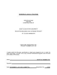
<strong>St</strong>. <strong>Cloud</strong> <strong>St</strong>ate University <strong>Chilled</strong> <strong>Water</strong> System<br />
KVAC<br />
KIEHLE VISUAL ARTS CENTER<br />
LH<br />
LAWRENCE HALL<br />
SH<br />
STEWART HALL<br />
51B<br />
51 BUILDING<br />
(BUSINESS BUILDING)<br />
R<br />
RIVERVIEW<br />
BH<br />
BROWN HALL<br />
AUXILIARY CHILLER<br />
92 GPM<br />
DIRECT BURY PIPE<br />
776 GPM<br />
DIRECT BURY PIPE<br />
S-1<br />
EST.* 100 GPM<br />
S-2<br />
111 GPM<br />
5-INCH STEEL<br />
FROM TUNNEL<br />
S-3<br />
300 GPM*<br />
89 GPM<br />
FCU<br />
92 THUS<br />
155 GPM<br />
AHU 2<br />
AHU 1<br />
36<br />
57<br />
GPM<br />
GPM<br />
FLOW<br />
METER<br />
6-INCH STEEL<br />
FROM TUNNEL<br />
248 GPM<br />
8-INCH STEEL<br />
879 GPM<br />
S-3<br />
128<br />
GPM<br />
S-2<br />
92<br />
GPM<br />
S-1<br />
92<br />
GPM<br />
S-8<br />
131<br />
GPM<br />
S-4<br />
205<br />
GPM<br />
S-5<br />
231<br />
GPM<br />
TO BUSINESS BLDG (51)<br />
8-INCH STEEL<br />
FROM STEWART<br />
68 GPM<br />
RTUI<br />
68<br />
GPM<br />
8-INCH<br />
DIRECT<br />
BURY<br />
VALVED<br />
OFF<br />
CURRENTLY<br />
SF 1<br />
76 GPM<br />
SF 2<br />
76 GPM<br />
4-INCH<br />
DIRECT BURY<br />
152 GPM<br />
AHU 4<br />
92<br />
GPM<br />
AHU 1<br />
750<br />
GPM<br />
AHU 2<br />
26<br />
GPM<br />
TUNNEL<br />
TO LAWRENCE<br />
& KIEHLE<br />
51B<br />
GC<br />
GARVEY COMMONS<br />
AHU 1<br />
AHU 2<br />
AHU 3<br />
42<br />
136 GPM<br />
120 GPM<br />
125 GPM<br />
GPM<br />
SHERBURNE HALL<br />
TAKE OFF<br />
MITCHELL<br />
HALL<br />
KIEHLE<br />
VISUAL ARTS CENTER<br />
KVAC<br />
4” CHWS&R<br />
5” CHWR<br />
5” CHWS<br />
LAWRENCE<br />
HALL<br />
LH<br />
6” CHWR<br />
6” CHWS<br />
6” CHWR<br />
6” CHWS<br />
SH<br />
6” CHWS<br />
6” CHWS&R<br />
STEWART<br />
HALL<br />
6” CHWR<br />
BUILDING 51<br />
8” CHWS<br />
8” CHWR<br />
R<br />
RIVERVIEW<br />
4” CHWS<br />
4” CHWR<br />
EASTMAN<br />
HALL<br />
8” CHWR<br />
8” CHWS<br />
WSB<br />
WICK SCIENCE BUILDING<br />
AHU 1<br />
150<br />
GPM<br />
AHU 2<br />
160<br />
GPM<br />
AHU 3<br />
170<br />
GPM<br />
AHU 4<br />
150<br />
GPM<br />
AHU 5<br />
170<br />
GPM<br />
AHU 6<br />
150<br />
GPM<br />
AHU 7<br />
175<br />
GPM<br />
AHU 8<br />
140<br />
GPM<br />
TO WICK<br />
ADDITION<br />
AMC<br />
6-INCH<br />
FROM<br />
TUNNEL<br />
6-iNCH STEEL FROM TUNNEL<br />
ATWOOD MEMORIAL CENTER<br />
AHU<br />
AHU 5<br />
13<br />
31<br />
AHU<br />
GPM<br />
21<br />
AHU 3<br />
101<br />
AHU<br />
AHU<br />
AHU 2<br />
GPM<br />
11<br />
22<br />
177<br />
GPM<br />
AHU<br />
AHU<br />
AHU<br />
AHU 1<br />
12<br />
24<br />
23<br />
182<br />
GPM<br />
AHU 4<br />
140<br />
GPM<br />
NORTH<br />
BENTON<br />
HALL<br />
HOLES<br />
HALL<br />
CAROL<br />
HALL<br />
BENTON HALL<br />
STEARNS<br />
HALL<br />
SHERBURNE<br />
HALL<br />
CASE<br />
HALL<br />
3” CHWS<br />
3” CHWR<br />
GARVEY<br />
COMMONS<br />
HILL<br />
HALL<br />
6” CHWS&R<br />
GC<br />
6” CHWS<br />
6” CHWR<br />
AMC<br />
6” CHWS&R<br />
ATWOOD<br />
MEMORIAL CENTER<br />
PERFORMING<br />
ARTS<br />
CENTER<br />
6” CHWS<br />
6” CHWR<br />
PA<br />
8” CHWS<br />
8” CHWR<br />
6” CHWS&R<br />
CENTENNIAL<br />
HALL<br />
CH<br />
12” CHWR<br />
12” CHWS<br />
BH<br />
BROWN HALL<br />
4” CHWS&R<br />
HH<br />
HEADLEY<br />
HALL<br />
12” CHWS<br />
12” CHWR<br />
12” CHWR<br />
8” CHWS<br />
8” CHWR<br />
ROBERT H. WICK<br />
SCIENCE BUILDING<br />
12” CHWS<br />
WICK ADDITION<br />
ISELF<br />
8” CHWS&R<br />
8” CHWS&R<br />
WA<br />
WSB<br />
6” CHWS&R<br />
6” CHWS&R<br />
ECC<br />
12” CHWS<br />
12” CHWS<br />
12” CHWR<br />
12” CHWR<br />
GREENHOUSE<br />
18” CHWS&R<br />
ENGINEERING<br />
AND COMPUTER<br />
CENTER<br />
20” CHWS<br />
20” CHWR<br />
SHOEMAKER HALL<br />
MAINT.<br />
BUILDING<br />
20” CHWS<br />
20” CHWR<br />
HEATING<br />
PLANT<br />
20” CHWR<br />
20” CHWS<br />
CHILLED<br />
WATER<br />
PLANT<br />
8” CHWS<br />
CWP<br />
8” CHWR<br />
8” CHWS&R<br />
HUSKY STADIUM<br />
WA<br />
8-INCH DIRECT BURY<br />
702 GPM<br />
AHU 1<br />
702<br />
GPM<br />
8-INCH DIRECT BURY PIPE<br />
1,265 GPM<br />
WICK ADDITION<br />
AHU 1<br />
702<br />
GPM<br />
ADMINISTRATIVE<br />
SERVICES<br />
BUILDING<br />
6” CHWS<br />
6” CHWR<br />
6” CHWS<br />
6” CHWR<br />
SRC<br />
STUDENT<br />
RECREATION<br />
CENTER<br />
AS<br />
EB<br />
CH<br />
CENTENNIAL HALL<br />
EDUCATION<br />
BUILDING<br />
HALENBECK HALL<br />
CWP<br />
CHILLED WATER PLANT<br />
6-INCH<br />
TO PAC DIRECT BURY<br />
491 GPM<br />
STATE-<br />
VIEW<br />
NORTH<br />
STATE-<br />
VIEW<br />
SOUTH<br />
MC<br />
12” CHWS<br />
CWR TEMP CONTROL VALVE<br />
12” CHWR<br />
CENTENNIAL<br />
1,413 GPM<br />
922 GPM<br />
RTU 4<br />
12-INCH DIRECT BURY<br />
313<br />
GPM<br />
AHU 1<br />
148 GPM<br />
FMS<br />
RTU 3<br />
313<br />
GPM<br />
JAMES<br />
W. MILLER<br />
LEARNING<br />
RESOURCES<br />
CENTER<br />
AHU 2<br />
148 GPM<br />
PA<br />
PERFORMING ARTS CENTER (PAC)<br />
6-INCH<br />
491 GPM<br />
DIRECT BURY<br />
MC<br />
MILLER<br />
LEARNING RESOURCES CENTER<br />
AS<br />
ADMINISTRATIVE SERVICES<br />
HH<br />
HEADLEY HALL<br />
EB<br />
EDUCATION BUILDING<br />
ECC<br />
ENGINEERING AND<br />
COMPUTER CENTER<br />
SRC<br />
STUDENT RECREATION CENTER<br />
F 5 F 15<br />
F 7<br />
F 12<br />
F 3<br />
24<br />
GPM<br />
9<br />
GPM<br />
47<br />
GPM<br />
40 GPM<br />
DUAL TEMP Hx<br />
43<br />
GPM<br />
25<br />
GPM<br />
PAC<br />
F 14 123<br />
F 17 31<br />
F 10<br />
59<br />
GMP<br />
GMP<br />
GMP<br />
FROM<br />
CENTENNIAL<br />
F 1<br />
90<br />
GPM<br />
AHU 1<br />
226<br />
GPM<br />
AHU 2<br />
291<br />
GPM<br />
853 GPM<br />
12-INCH<br />
DIRECT BURY PIPE<br />
AHU 3<br />
AHU 9<br />
AHU 6<br />
88<br />
62<br />
22<br />
GPM<br />
GPM<br />
GPM<br />
AHU 5<br />
115<br />
GPM<br />
AHU 4<br />
49<br />
GPM<br />
2 COILS<br />
153.5 ea<br />
307 GPM<br />
SF 1<br />
SF 2<br />
2 COILS<br />
95.5 ea<br />
191 GPM<br />
CW RETURN<br />
TEMP CTRL VALVE<br />
FROM<br />
HEADLEY<br />
6-INCH<br />
DIRECT BURY<br />
498 GPM<br />
RTU<br />
1<br />
4-INCH<br />
FROM<br />
TUNNEL<br />
RTU<br />
2<br />
AHU 2<br />
AHU 3<br />
AHU<br />
1<br />
6-INCH<br />
DIRECT BURY<br />
CW RETURN<br />
TEMP CTRL<br />
304 GPM<br />
6-INCH<br />
DIRECT BURY<br />
AHU 2<br />
52<br />
GPM<br />
AHU 3<br />
38<br />
GPM<br />
AHU 1<br />
52<br />
GPM<br />
RTU 5<br />
89<br />
GPM<br />
AHU 4<br />
31<br />
GPM<br />
RTU 6<br />
42<br />
GPM<br />
AHU 1<br />
413<br />
GPM<br />
FUTURE<br />
8-INCH DIRECT BURY<br />
516 GPM<br />
AHU 2<br />
103<br />
GPM<br />
November 2011 | Prepared by McKinstry | 8451 Xerxes Avenue N., Brooklyn Park, MN 55444 | 763.767.0304 | mckinstry.com
2. <strong>Chilled</strong> <strong>Water</strong> System
2. <strong>Chilled</strong> <strong>Water</strong> System<br />
System Observations<br />
This study addresses three separate yet interconnected systems: individual building loads, the chilled water<br />
distribution loop, and the chilled water plant itself. While there is independent activity and function in each of<br />
the three systems, they do—and must—interact continuously with each other. This section identifies how that<br />
interaction occurs and how system controls must interact continuously to provide the desired performance.<br />
When properly designed and installed, the chilled water system should efficiently and effectively provide the<br />
desired cooling to all connected buildings.<br />
Many parts of the chilled water system are properly designed and installed, and the system works well despite<br />
certain problems. In some cases, these problems result from additions or alterations made to parts of the<br />
system without adequately addressing their impact on overall system operation. Examples of this include the<br />
inadequacy of delivery pipe size in Atwood Memorial Center, the temperature disparity that occurs in the<br />
chilled water supply to buildings, and the inability to maintain the supply temperature setpoint on design days.<br />
Each of these problems needs to be corrected before adding capacity to the chilled water plant. McKinstry’s<br />
team is concerned that the chilled water system may be incapable of handling added load. McKinstry and the<br />
University must determine what to do if the system cannot handle added load and identify the best approach<br />
to adding capacity.<br />
McKinstry documented the capacity of the chilled water plant and identified two key issues: the outlet water<br />
temperature setpoint and flow control between the chiller production loops and the system distribution loop.<br />
We have quantified the building loads and identified their peak load as connected to the current distribution<br />
loop. Within the confines of building and campus diversity, both systems are somewhat matched.<br />
Deviation occurs in connecting the chilled water plant output to the individual building input requirements.<br />
System distribution pumps do not adequately deliver to buildings the proper<br />
water volume at the proper temperature. The distribution system’s pumps<br />
inadequacies are augmented by the deficient control within the buildings’<br />
tertiary pumps and control valves.<br />
Graph 1 below demonstrates the desired differential in PSI, between the<br />
system supply water pressure and system return water pressure. The intent of<br />
this control point is to adjust the system distribution pump speed to maintain<br />
this value at the differential pressure sensor/transmitter located in the system<br />
distribution loop out on the campus.<br />
GRAPH 1<br />
PSI<br />
6<br />
4<br />
2<br />
0<br />
Delta P Setpoint<br />
5
2. <strong>Chilled</strong> <strong>Water</strong> System<br />
Graphs 2, 3, and 4 below demonstrate the month, week, and day values of what the actual system differential<br />
pressure is over time. With a setpoint of 5.5 PSI, the system hunts from nearly 15 PSI to negative 2 PSI. The<br />
system is often below setpoint and frequently in the negative range. The month and week data demonstrate<br />
the impact of three-way valves and starting and stopping tertiary pumps.<br />
GRAPH 2<br />
PSI<br />
16<br />
14<br />
12<br />
10<br />
8<br />
6<br />
4<br />
2<br />
0<br />
-2<br />
<strong>Chilled</strong> <strong>Water</strong> Plant<br />
August 5–September 5, 2011<br />
CHW Differential Pressure<br />
7/31/2011<br />
8/5/2011<br />
8/10/2011<br />
8/15/2011<br />
8/20/2011<br />
8/25/2011<br />
8/30/2011<br />
9/4/2011<br />
9/9/2011<br />
6
2. <strong>Chilled</strong> <strong>Water</strong> System<br />
GRAPH 3<br />
PSI<br />
16<br />
14<br />
12<br />
10<br />
8<br />
6<br />
4<br />
2<br />
0<br />
-2<br />
<strong>Chilled</strong> <strong>Water</strong> Plant<br />
August 28–September 3, 2011<br />
CHW Differential Pressure<br />
8/27/2011<br />
8/28/2011<br />
8/29/2011<br />
8/30/2011<br />
8/31/2011<br />
9/1/2011<br />
9/2/2011<br />
9/3/2011<br />
9/4/2011<br />
9/5/2011<br />
Graph 4 demonstrates the system performance for a 24-hour period. The differential pressure appears to<br />
come under control during the lighter night load, but it bottoms out and remains in the negative range for<br />
virtually the entire day load.<br />
7
2. <strong>Chilled</strong> <strong>Water</strong> System<br />
GRAPH 4<br />
PSI<br />
16<br />
14<br />
12<br />
10<br />
8<br />
6<br />
4<br />
2<br />
0<br />
-2<br />
Chiller Plant<br />
September 1, 2011<br />
CHW Differential Pressure<br />
7:12 PM<br />
12:00 AM<br />
4:48 AM<br />
9:36 AM<br />
2:24 PM<br />
7:12 PM<br />
12:00 AM<br />
The speed at which the control valves—and in some cases the tertiary pumps—respond to control signals<br />
within each building is much faster than the response of the VFDs on the system distribution pumps; the<br />
result is wild swings in pressure between supply and return.<br />
The frequency of data points in the negative range is proportional to the time tertiary pumps over-pressure<br />
the return system. The flow controls (changes in flow modulation) on the tertiary pumps, whether it is VFDs<br />
controlling the actual pump speed or two-way valves controlling the output, are too fast for a corresponding<br />
adjustment by the differential pressure sensor and the system pump to respond to properly. The system<br />
cannot stabilize and wild swings result.<br />
Three-way valves themselves will cause the differential pressure sensor to see a continuous low reading and<br />
transmit a signal to continuously increase VFD speed. Pump speed can increase to its limit and line voltage,<br />
yet never achieve the desired setpoint. As long as a control valve only diverts water around a load, as<br />
opposed to restricting flow, differential pressure cannot be achieved.<br />
Control valves that actually reduce flow through a system instead of diverting it around a load would cause<br />
the pressure change necessary to control the system distribution pumps. A two-way control valve does this.<br />
As load decreases, two-way control valves close. As they close back, pressure is created that will be greater<br />
on the supply pipe than on the return pipe. This pressure difference is transmitted to the distribution pump<br />
VFD which—as actual pressure exceeds setpoint—causes the VFD signal to reduce, thereby slowing the pump.<br />
As the distribution system pump slows, less water flows. When the load increases and more cooling is<br />
required, the control valve begins to open, the system pressure differential begins to drop, and the pump<br />
begins speeding up.<br />
When the distribution pump is at constant speed and near-constant flow rate, the chilled water plant needs to<br />
supply the proper quantity of chilled water to the pump inlet. If the chilled water plant pump and the system<br />
distribution pump were the same size, operated at the same speed, and had the same head requirement, the<br />
system would have proper flow balance. Load change would only impact the chiller itself and the function<br />
would be that of a constant volume system.<br />
8
2. <strong>Chilled</strong> <strong>Water</strong> System<br />
In this system, the distribution loop pumps are 33% larger than the chilled water plant pumps and flow<br />
correspondingly more water, 3,600 gallons per minute (GPM), at maximum speed (design flow). The campus<br />
distribution system was designed as a variable flow system.<br />
During low load periods, one chiller can support the cooling requirements of the campus. With one chiller<br />
operating, the primary chilled water flow would be 2,400 GPM, the constant flow requirement of the chiller.<br />
This low load period ought to translate into a lower flow requirement for the cooling system as well. The<br />
distribution pump ought to slow down to match or nearly match the flow through the chiller.<br />
With the distribution pump receiving a signal to run at maximum speed, it will always flow more water than<br />
does the chiller. To support the required flow in the system distribution pump, the water will return from the<br />
system at the same rate it is supplied and, as it cannot go through the chiller, must go back into the<br />
distribution loop. This warm return water blends with the cold chiller water via the decoupler loop and the<br />
distribution pumps will then supply warmer-than-desired chilled water. When the buildings receive warm<br />
water via the distribution system, the AHUs cannot achieve discharge air setpoints and spaces served by these<br />
AHUs will get too warm. The response to this circumstance has been to reduce the chilled water setpoint on<br />
the chiller. Colder water blended with warmer water may result in chilled water being supplied to the AHUs at<br />
the proper temperature.<br />
A second chiller starts as the load increases and the parameters established for multiple chiller operations are<br />
met. The second chiller provides an additional 2,400 gallons to the distribution system, now exceeding the<br />
flow capacity of the system distribution pumps by 1,200 GPM. The distribution pumps no longer blend return<br />
and supply water, and the supply water temperature approaches setpoint. <strong>Water</strong> unused by the distribution<br />
pump blends with return water at the decoupler and returns to the inlet of the chillers at a reduced<br />
temperature.<br />
It would be appropriate to start the second distribution pump and parallel both pumps on a properly applied<br />
differential pressure signal, but the system requirements and the pumps’ capabilities do not appear to operate<br />
in this mode.<br />
9
3. <strong>Chilled</strong> <strong>Water</strong> Plant
3. <strong>Chilled</strong> <strong>Water</strong> Plant<br />
10
3. <strong>Chilled</strong> <strong>Water</strong> Plant<br />
<strong>Chilled</strong> <strong>Water</strong> Plant Details<br />
The central chilled water plant consists of the following equipment:<br />
• Two Trane Model 1280 Centrifugal Chillers<br />
• One Bell & Gossett Primary <strong>Chilled</strong> <strong>Water</strong> Pump serving each chiller<br />
• One Bell & Gossett Condenser <strong>Water</strong> Pump servicing each chiller<br />
• Four BAC cooling towers, commonly linked, serving both chillers<br />
• Two Bell & Gossett Secondary Distribution Pumps<br />
• Interconnecting piping<br />
• Digital controls<br />
This chilled water plant was designed to produce 4,500 tons of cooling for distribution to the campus. The<br />
chilled water piping entering and leaving the chilled water plant is adequately sized for this capacity, as is the<br />
condenser piping. Physical space is available to add a chiller. Piping runouts were provided for this purpose.<br />
The structural capability of the roof to support additional cooling tower capacity is still under investigation.<br />
The existing chillers are capable of producing 2,560 tons (1,280 x 2) under design conditions. Selection data<br />
provided by Trane indicate that the chillers were designed to operate at 44°F leaving water temperature.<br />
Campus cooling issues have caused leaving water temperatures to be reset down to 40°F to satisfy space<br />
cooling needs. This temperature reset results in de-rating the chiller capacity. At 40°F outlet temperature, the<br />
chillers are only capable of producing 1,020 tons each, a 20% reduction in output capacity.<br />
The intent of the chilled water plant design was to operate the plant in a primary/secondary decoupled flow<br />
condition. The primary loop consists of two individual loops with one chiller and one chilled water pump on<br />
each. Flow through each chiller is assumed to be at a constant rate and must be proven to the chiller control<br />
panel before start-up is permitted. Flow rate through each chiller is the rated output of its associated chilled<br />
water pump, documented to be 2,400 GPM at 45 feet of water head pressure, the head required to overcome<br />
the pressure drop across the evaporator and interconnected piping.<br />
The secondary piping loop consists of two distribution pumps sized to deliver 3,600 GPM at 116 feet head<br />
pressure. The head pressure rating selected is intended to distribute the required volume of chilled water to<br />
the building loads throughout the campus. Both secondary pumps are equipped with VFDs that allow the<br />
pumps to be individually slowed down or sped up to supply the desired volume of chilled water. A DPT located<br />
in the secondary system controls the VFD output current and thereby the speed of the pumps. A decoupler<br />
acts as the bridge between the primary and secondary pumping loops. Its purpose is to allow water to flow in<br />
either direction between the primary and secondary loops, depending on flow requirements of the secondary<br />
loop and the number of chillers operating.<br />
During our investigation we noted that the shut-off valve in the decoupler was closed. We speculate that this<br />
valve was closed in response to the same concern that resulted in chiller outlet temperatures being reset<br />
lower: a need for additional cooling. The decoupler can allow warmer-than-desired supply water to be<br />
distributed to the loads in single chiller operation when distribution pumps are not being controlled properly.<br />
Closing this valve forces water flow though the chillers, whether they are operating or not. This would have<br />
only been partially successful in improving campus cooling system performance since we observed water<br />
flowing through the idle chiller and blending with the outlet water of the operating chiller, causing warm water<br />
to be distributed anyway. We opened the shut-off valve during the investigation to measure impact on the<br />
distribution system and individual buildings. McKinstry conducted additional tests to determine how flow could<br />
be balanced between chillers and distribution loops.<br />
By design, when one chiller is operating, the distribution pump VFD should reduce the speed of the<br />
distribution pump to match the flow of water through the chiller. This was not occurring during our initial<br />
tests. Indications are that the pressure differential never achieved setpoint and data from the transmitter<br />
often displayed a negative value. Until the setpoint is reached, the VFD will continue to increase pump speed,<br />
11
3. <strong>Chilled</strong> <strong>Water</strong> Plant<br />
resulting in full speed operation at all times. It appears that control of the three-way valves and tertiary<br />
pumps allow the return loop to be over-pressured, which would account for the negative readings observed.<br />
We attempted to operate two distribution pumps simultaneously; this test was also not successful. Differential<br />
pressure control could not be applied to both pumps simultaneously. Pump control is individually written in the<br />
DDC program for each pump and cannot be combined without re-programming. Our desired outcome would<br />
have been to operate both pumps in parallel, responding jointly to the control signal from the differential<br />
pressure transmitter.<br />
We attempted to manually operate the distribution pumps in parallel. McKinstry’s team hypothesized that two<br />
pumps in parallel would need to run at approximately 60% of their rated speed to produce the same flow one<br />
pump produced at 100% speed. This condition was not achieved either. Both pumps were ramped up over<br />
85% of their range before the flow meter being observed achieved the flow rate one pump previously<br />
manifested. It appears the distribution pumps were selected to operate redundantly and never in parallel.<br />
Further analysis is necessary, but it appears the chilled water distribution system is limited to the output<br />
capacity of one distribution pump at this time.<br />
Chiller performance appears to be approaching the limit of their combined capability considering the reduced<br />
capacity noted above. The chart below demonstrates the load profile for three consecutive design days in July.<br />
It indicates that the plant operates with both chillers drawing at or near their capacity. Chiller 2 appears to lag<br />
slightly below Chiller 1, even when it is designated lead chiller. It could indicate increased fouling of either<br />
evaporator or condenser bundles.<br />
GRAPH 1<br />
120<br />
Chiller Performance<br />
July 18–July 22, 2011<br />
100<br />
80<br />
% RLA<br />
60<br />
40<br />
20<br />
Chiller 1 %RLA<br />
Chiller 2 %RLA<br />
0<br />
7/18/11 0:00<br />
7/18/11 7:30<br />
7/18/11 15:00<br />
7/18/11 22:30<br />
7/19/11 6:00<br />
7/19/11 13:30<br />
7/19/11 21:00<br />
7/20/11 4:30<br />
7/20/11 12:00<br />
7/20/11 19:30<br />
7/21/11 3:00<br />
7/21/11 10:30<br />
7/21/11 18:00<br />
7/22/11 1:30<br />
7/22/11 9:00<br />
7/22/11 16:30<br />
12
3. <strong>Chilled</strong> <strong>Water</strong> Plant<br />
A similar pattern manifests on a design day with fall classes in session. The graph below indicates Chiller 1<br />
being added at approximately 7:00 AM September 1st and remaining on until approximately 10:00 PM. For a<br />
four- to five-hour period between 2:30 and 8:00 PM the system was unable to achieve setpoint for chilled<br />
water output temperature.<br />
GRAPH 2<br />
CHW Temperature (°F)<br />
55<br />
53<br />
51<br />
49<br />
47<br />
45<br />
43<br />
41<br />
39<br />
37<br />
35<br />
7:12 PM<br />
12:00 AM<br />
Chillers — September 1, 2011<br />
Setpoint vs. Leaving Temperatures<br />
4:48 AM<br />
9:36 AM<br />
2:24 PM<br />
7:12 PM<br />
12:00 AM<br />
Setpoint<br />
Chiller 1 Leaving Temp<br />
Chiller 2 Leaving Temp<br />
The graph below indicates that during the period where chilled water setpoint was not being maintained, the<br />
running load amps (RLA) of both chillers was near 100%. Distribution pump speed was at 60Hz or 100% of its<br />
capability as well.<br />
GRAPH 3<br />
Chillers—September 1, 2011<br />
%RLA vs. Pump Speed<br />
120<br />
100<br />
80<br />
60<br />
40<br />
20<br />
0<br />
Chiller 1 %RLA<br />
Chiller 2 %RLA<br />
Pump Speed<br />
12:00 AM<br />
2:30 AM<br />
5:00 AM<br />
7:30 AM<br />
10:00 AM<br />
12:30 PM<br />
3:00 PM<br />
5:30 PM<br />
8:00 PM<br />
10:30 PM<br />
13
4. Distribution Loop
4. Distribution Loop<br />
Distribution Loop Details<br />
The chilled water distribution system begins with two VFD-equipped secondary pumps located in the chilled<br />
water plant. Each of these pumps is sized to deliver approximately 3,500 GPM to the campus. These pumps<br />
are designated as secondary because they are not directly connected to the primary chiller circuit and can<br />
operate independently of the water flow requirements of the chillers.<br />
<strong>Chilled</strong> water exits the chilled water plant through a single 20-inch supply pipe and returns through a 20-inch<br />
return pipe. The supply and return piping split into four separate legs to distribute water to various campus<br />
building loads. Table 1 indentifies the buildings on each leg and their associated chilled water flow design<br />
requirements in GPM.<br />
TABLE 1<br />
Design East Leg<br />
Design Central Leg<br />
Design West Leg<br />
Design South Leg<br />
Bldg<br />
GPM Bldg<br />
GPM Bldg<br />
GPM Bldg<br />
GPM<br />
Eastman Hall<br />
0 Wick Science<br />
1265 Wick Annex<br />
702 <strong>St</strong>udent Rec Ctr<br />
516<br />
Riverview<br />
151 Brown Hall<br />
789 ECC<br />
302 Total<br />
516<br />
Total<br />
151 Atwood Center * 1037 Education<br />
* 577<br />
Garvey Commons<br />
Sherburne Hall<br />
51 Building<br />
<strong>St</strong>ewart Hall<br />
Lawrence hall<br />
Kiehle Hall<br />
427 Headley<br />
* 65<br />
* 28 Centennial<br />
922<br />
228 PAC<br />
500<br />
879 Administration<br />
498<br />
248 Miller<br />
849<br />
* 343 Total<br />
4,415<br />
Total<br />
5,244<br />
* Calculated Values<br />
*Where design data is missing or not available calculations using industry standards define the anticipated<br />
loads.<br />
The data presented in Table 1 represents the design data for each listed building’s connected load. Design<br />
data consists of the cooling load for each building based upon a fully occupied state on a day when outside air<br />
temperatures are at design conditions: an 85°F dry bulb temperature and 68°F wet bulb temperature.<br />
The potential for a building to operate at its design condition is relatively remote as it is highly unlikely that all<br />
conditioned areas of a building will be fully occupied at all times. Lights are not on everywhere all the time;<br />
equipment loads, refrigerators, computers, printers, and so on will not be simultaneously operating at peak<br />
output all the time. Classrooms, corridors, offices, and meeting rooms will not be at occupancy capacity all the<br />
time.<br />
Operating cooling load conditions are accounted for through application of diversity factors which are typically<br />
individual building based. When buildings are served by a shared cooling source such as a campus distribution<br />
system, the effect of building diversity is amplified and will significantly impact the distribution system<br />
operation relative to connected load. Determining the variance in cooling flow requirements by modeling can<br />
be cost prohibitive. Utilization of empirical data and known changes for estimating system cooling flows can be<br />
cost effective and are generally applied to these conditions.<br />
The current campus distribution system connected cooling load requires a 10,875 GPM flow rate to satisfy all<br />
of the buildings at their design load. Current observed system operation utilizes one of two secondary pumps<br />
to provide the required chilled water. Trend data indicates that the peak flow rate is 3,900–4,300 GPM with<br />
pump VFD operating at 60Hz. Hot day (design day) trend data shows the single distribution pump reaching<br />
maximum capacity at 6:00 AM and continuing until 9:00 PM.<br />
14
4. Distribution Loop<br />
As individual building flow data is not available, distribution is based upon the ratio of each building’s design<br />
load. Table 2 below represents the minimum distribution criteria for each building based upon the trend value<br />
of 3,900 GPM. In each individual building, the chilled water flow rate is between the minimum value listed in<br />
Table 2 and the design value listed in Table 1. As demand increases in one building it reduces in another,<br />
thereby maintaining a degree of equilibrium. On those occasions when demand exceeds available capacity,<br />
deviation from cooling setpoints occurs.<br />
TABLE 2<br />
Current East Leg<br />
Current Central Leg<br />
Current West Leg<br />
Current South Leg<br />
Bldg GPM Bldg GPM Bldg<br />
GPM Bldg<br />
GPM<br />
Eastman Hall<br />
0 Wick Science<br />
457 Wick Annex<br />
253 <strong>St</strong>udent Rec Ctr<br />
186<br />
Riverview<br />
55 Brown Hall<br />
271 ECC<br />
110 Total<br />
186<br />
Total<br />
55 Atwood Center * 548 Education<br />
* 209<br />
Garvey Commons<br />
Sherburne Hall<br />
51 Building<br />
<strong>St</strong>ewart Hall<br />
Lawrence hall<br />
Kiehle Hall<br />
Total<br />
153 Headley<br />
* 23<br />
* 23 Centennial<br />
333<br />
82 PAC<br />
177<br />
317 Administration<br />
180<br />
90 Miller<br />
308<br />
* 125 Total<br />
1,593<br />
2,066<br />
* Calculated Values<br />
Redistribution of chilled water as it applies to the East and Central legs of the distribution loop is possible<br />
because of the extension of direct-buried supply and return piping from Riverview to Building 51. Table 3<br />
demonstrates what the distributed flow rates would be with the valves at the South end of Building 51 opened<br />
and the valves at the <strong>St</strong>ewart Hall take-off in the tunnel closed.<br />
TABLE 3<br />
Bldg<br />
Eastman Hall<br />
Riverview<br />
New East Leg<br />
New Central Leg<br />
New West Leg<br />
New South Leg<br />
GPM Bldg<br />
GPM Bldg<br />
GPM Bldg<br />
GPM<br />
0 Wick Science<br />
1265 Wick Annex<br />
702 <strong>St</strong>udent Rec Ctr<br />
516<br />
151 Brown Hall<br />
789 ECC<br />
302 Total<br />
516<br />
51 Building<br />
<strong>St</strong>ewart Hall<br />
Lawrence hall<br />
Kiehle Hall<br />
Total<br />
* 228 Atwood Center * 1037 Education<br />
* 577<br />
879 Garvey Commons 427 Headley<br />
* 65<br />
248 Sherburne Hall<br />
28 Centennial<br />
922<br />
* 343 Total<br />
3,546 PAC<br />
500<br />
1,849 Administration<br />
498<br />
Miller<br />
Total<br />
This new distribution plan would provide adequate chilled water supply to satisfy the needs of the East and<br />
Central legs as they are currently defined and provide some level of expansion and increased chilled water<br />
demand in the future.<br />
Future loads must be considered as campus growth and alterations to existing buildings occur. Data provided<br />
in the Campus Comprehensive Plan indicated the following education buildings were scheduled to be added or<br />
identified for remodel and/or upgrade of their infrastructure: Eastman Hall, ISELF, Headley, and Halenbeck.<br />
The GPM requirements of these buildings were determined from plans in development or data derived from<br />
standardized cooling applications. These additional loads must be considered in the distribution system<br />
analysis. Halenbeck Hall is currently being studied for upgrades that are expected to include air conditioning.<br />
The data provided is based upon square footage that may or may not be included. The GPM flow is contingent<br />
upon chilled water supply temperatures of 42°F.<br />
849<br />
4,415<br />
* Calculated Values<br />
15
4. Distribution Loop<br />
TABLE 4<br />
Bldg<br />
Eastman Hall<br />
ISELF<br />
Headley<br />
Halenbeck<br />
GPM<br />
265<br />
950<br />
302<br />
XXX<br />
Residence halls on campus represent the next level of potential load for the chilled water system. These<br />
buildings are currently heated from the central heating plant, but do not have air conditioning installed except<br />
for the common areas of Sherburne Hall.<br />
TABLE 5<br />
Residence<br />
Bldg S.F.<br />
(Gross)<br />
Cooling<br />
Tons<br />
<strong>Chilled</strong><br />
<strong>Water</strong><br />
GPM<br />
CHW<br />
Delta T Net S.F. S.F. / Ton<br />
CFM/S.F.<br />
(combined)<br />
Mitchell Hall 107,890 188 452 10 106,342 565 0.75<br />
Hill Hall 47,807 59 142 10 30,700 520 0.71<br />
Case Hall 40,492 66 159 10 34,304 517 0.73<br />
<strong>St</strong>earns Hall 81,180 138 332 10 70,249 508 0.74<br />
Holes Hall 80,213 134 322 10 68,312 510 0.74<br />
Benton Hall 40,595 44 107 10 21,936 494 0.68<br />
North Benton Hall 20,297 22 53 10 14,328 645 0.75<br />
Sherburne Hall 125,573 162 390 10 77,574 478 0.76<br />
Shoemaker Hall 107,428 191 458 10 89,881 471 0.78<br />
Totals 651,475 1006 2414 513,626<br />
Table 5 represents estimated operational load with demand-controlled ventilation (DCV). While the values<br />
shown in Table 5 are inclusive of all load requirements, it is unlikely that dormitory rooms in the residence<br />
halls will be added to the central chiller system. The cost of distributing constant volume or variable air<br />
volume (VAV) air handling systems to dorm rooms may be prohibitive. It is more likely that common areas,<br />
lobbies, activity areas, etc., would be retrofitted with AHUs than the dorm rooms because those areas would<br />
benefit from a distributed chilled water source. The total calculated load is included in the distribution plan at<br />
this time to allow for new technology that may make dorm room connections to a distributed system viable. If<br />
it is determined that package terminal air conditioning (PTAC) units or other similar technology will be used,<br />
the displaced chilled water can represent excess capacity.<br />
These loads are likely to be added to the existing distribution system based upon their proximity to the three<br />
primary loops plus the addition of Halenbeck to the South loop.<br />
16
4. Distribution Loop<br />
TABLE 6<br />
Future East Leg Future West Leg Future Central Leg<br />
Future South Leg<br />
Bldg GPM Bldg GPM Bldg<br />
GPM Bldg GPM<br />
Eastman Hall * 265 Wick Annex<br />
702 Wick Science 1265 <strong>St</strong>udent Rec Ctr 516<br />
Riverview 152 ISELF<br />
950 Brown Hall 750 Halenbeck Hall * XXX<br />
51 Building * 300 ECC<br />
304 Atwood Center * 1517 Total<br />
<strong>St</strong>ewart Hall 879 Education<br />
* 580 Garvey Commons 423<br />
Lawrence hall 248 Headley<br />
* 302 Sherburne Hall * 390<br />
Mitchell Hall 452 Centennial<br />
922 Hill / Case Hall * 243<br />
Kiehle Hall 345 PAC<br />
491 <strong>St</strong>earns Hall * 271<br />
Total<br />
2,641 Administration<br />
498 Holes Hall * 321<br />
Shoemaker<br />
* 458 Total<br />
4,345<br />
* Calculated Values<br />
Miller<br />
Total<br />
853<br />
6,060<br />
This table represents the design flow requirements of all the buildings identified for possible addition to the<br />
chilled water system, but does not address their potential diversity. If an increase in student body population<br />
is significant, if research activity expands and requires increased ventilation, and if standards for outside air<br />
increase again, system load will increase substantially.<br />
The tables on the following page demonstrate flow ranges in the individual loops. As long as diversity remains<br />
as currently defined, the chilled water distribution system can function as intended.<br />
17
4. Distribution Loop<br />
Design<br />
GPM<br />
Current<br />
GPM<br />
Cumulative<br />
High GPM<br />
Cumulative<br />
Low GPM<br />
Existing<br />
Pipe Size<br />
Max<br />
Flow<br />
Bldg<br />
Eastman Hall 0 0 1,924 724 8 1500<br />
Riverview 152 57 1,924 724 8 1500<br />
51 Building * 228 113 1,772 667 8 1500<br />
<strong>St</strong>ewart Hall 879 331 1,472 554 6 900<br />
Lawrence hall 248 93 593 223 6 900<br />
Kiehle Hall * 345 130 345 130 6 900<br />
Total<br />
1,924 724<br />
New East Leg Flow Range<br />
Design<br />
GPM<br />
New Central Leg Flow Range<br />
Current<br />
GPM<br />
Cumulative<br />
High GPM<br />
Cumulative<br />
Low GPM<br />
Existing<br />
Pipe Size<br />
Max<br />
Flow<br />
Bldg<br />
Wick Science 1265 476 3,987 1,512 12 3500<br />
Brown Hall 750 282 2,722 1,036 8 1500<br />
Atwood Center * 1037 571 1,972 754 8 1500<br />
Garvey Commons 423 159 455 183 6 900<br />
Sherburne Hall 32 24 32 24 3 225<br />
Total<br />
3,987 1,512<br />
Bldg<br />
Wick Annex<br />
ECC<br />
Education<br />
Miller<br />
Administration<br />
Headley<br />
Centennial<br />
PAC<br />
Total<br />
Design<br />
GPM<br />
West Leg Flow Range<br />
Current<br />
GPM<br />
Cumulative<br />
High GPM<br />
Cumulative<br />
Low GPM<br />
Existing<br />
Pipe Size<br />
Max<br />
Flow<br />
702 264 4,415 1,660 12 3500<br />
304 114 3,713 1,396 12 3500<br />
* 580 218 3,409 1,282 12 3500<br />
853 321 2,829 1,064 12 3500<br />
498 187 1,976 743 12 3500<br />
* 65 24 1,478 556 12 3500<br />
922 347 1,413 532 8 1500<br />
500 185 491 185 6 900<br />
4,415 1,660<br />
Potential for Trouble<br />
* Calculated Values<br />
18
5. 51 Building
Building 51 (Business Building)<br />
Year Built 1968<br />
Renovations/Additions 1993, 2008<br />
Gross Square Feet 52,085<br />
Occupancy 495<br />
Usage Instruction<br />
Load GPM<br />
Cooling<br />
Tons EWT °F LWT °F<br />
Design<br />
Delta T<br />
RTU-1 68 34 44 56 12<br />
Total 228 114 44 56 12<br />
Information<br />
Source<br />
Construction<br />
Documents<br />
Estimated<br />
Building Occupancy Schedu<br />
(Fall-Spring)<br />
le<br />
Sunday Monday Tuesday Wednesday Thursd ay<br />
Friday<br />
Saturday<br />
Open Close Open Close Open Close Open Close Open Close Open Close Open Close<br />
Closed 0700 2200 0700 2200 0700 2200 0700 2200 0700 1700 1200 1700<br />
Building Occupancy Schedu<br />
(Summer)<br />
le<br />
Sunday Monday Tuesday Wednesday Thursday Friday<br />
Saturday<br />
Open Close Open Close Open Close Open Close Open Close Open Close Open Close<br />
Closed 700 1700 700 1700 700 1700 700 1700 700 1700 Closed<br />
AHU Operating Schedule Sunday Monday Tuesday Wednesday Thursd ay<br />
Friday<br />
Saturday<br />
RTU-1 <strong>St</strong>art <strong>St</strong>op <strong>St</strong>art <strong>St</strong>op <strong>St</strong>art <strong>St</strong>op <strong>St</strong>art <strong>St</strong>op <strong>St</strong>art <strong>St</strong>op <strong>St</strong>art <strong>St</strong>op <strong>St</strong>art <strong>St</strong>op<br />
No Schedule 0545 2130 0545 2130 0545 2130 0545 2130 0545<br />
2130<br />
No Schedule
5. 51 (Business) Building<br />
19
5. 51 (Business) Building<br />
General Building Description<br />
The 51 Building contains classrooms and general use offices. Its occupancy is consistent with a university<br />
campus education building for normal school year use.<br />
HVAC System Description<br />
A single roof-mounted air handling unit provides air conditioning for the<br />
primary purpose of dehumidification. Heating systems are turned off during<br />
cooling season and there is no reheat provided for comfort cooling.<br />
The single rooftop unit (RTU) is equipped with a three-way control valve to<br />
adjust and control the flow of chilled water to the cooling coils.<br />
Base-mounted, end suction tertiary pumps boost system pressure to the<br />
RTU. The pumps are not equipped with variable frequency drives (VFD).<br />
GRAPH 1<br />
CHW Delta T (°F)<br />
30<br />
25<br />
20<br />
15<br />
10<br />
5<br />
0<br />
51 Building<br />
OAT vs. Delta T<br />
y = 0.2615x - 10.268<br />
45 50 55 60 65 70 75 80 85 90<br />
Outside Air Temperature (°F)<br />
<strong>Chilled</strong> <strong>Water</strong> Energy Use<br />
The trend line in Graph 1 above indicates that the three-way valve operates as designed. As the load<br />
increases, the difference in supply and return water temperatures (Delta T) increases. During a normal<br />
operating cycle, the valve bypasses up to an outside air temperature of 56–57°F, modulates between 58°F<br />
and 83°F, and maintains full flow through the coil above 84°F.<br />
20
5. 51 (Business) Building<br />
CHW Delta T (°F)<br />
GRAPH 2<br />
51 Building—September 1, 2011<br />
Time of Day vs. Delta T<br />
18<br />
16<br />
14<br />
12<br />
10<br />
8<br />
6<br />
4<br />
2<br />
0<br />
7:12 PM 12:00 AM 4:48 AM 9:36 AM 2:24 PM 7:12 PM 12:00 AM<br />
GRAPH 3<br />
80<br />
Building 51<br />
CHW Supply and Return Temperatures<br />
CHW Temperature (°F)<br />
75<br />
70<br />
65<br />
60<br />
55<br />
50<br />
45<br />
Supply Temp, °F<br />
Return Temp, °F<br />
40<br />
7/31/11<br />
8/5/11<br />
8/10/11<br />
8/15/11<br />
8/20/11<br />
8/25/11<br />
8/30/11<br />
9/4/11<br />
9/9/11<br />
21
5. 51 (Business) Building<br />
70<br />
GRAPH 4<br />
Building 51—September 1, 2011<br />
CHW Supply and Return Temperatures<br />
65<br />
CHW Temperature (°F)<br />
60<br />
55<br />
50<br />
45<br />
Supply Temp, °F<br />
Return Temp, °F<br />
40<br />
7:12 PM 12:00 AM 4:48 AM 9:36 AM 2:24 PM 7:12 PM 12:00 AM<br />
Cooling System Performance<br />
• Graphs 2, 3, and 4 above indicate that the building load commences around 2:00 AM and maintains<br />
the desired setpoint until 10:00 PM Monday through Friday with weekend shutdowns. It appears that<br />
pre-cooling occurs until approximately 7:00 AM when occupancy may begin.<br />
• This data is inconsistent with the operating schedule established for the building and does not appear<br />
to be coincidental with the AHU operating schedule.<br />
• These inconsistencies will likely be identified and corrected by the re-commissioning study currently<br />
underway.<br />
Building Impact on <strong>Chilled</strong> <strong>Water</strong> System<br />
• The three-way valve on the RTU allows colder-than-desired return chilled water temperature.<br />
• The tertiary pumps may be over-pressurizing the return water system as a result of the flow-through<br />
nature of the three-way valve.<br />
22
5. 51 (Business) Building<br />
Recommendations<br />
• Open South-end chilled water valves and reverse flow through building.<br />
• Replace the three-way cooling valve on the RTU with a two-way valve or install a shutoff valve in the<br />
return leg of the three-way to make it perform as a two-way.<br />
• Add VFD control to the tertiary pumps along with a properly located differential pressure transmitter<br />
to control it.<br />
• Install BTU chilled water meter in lower level mechanical room.<br />
• Balance water flow to tertiary pumps and to the RTU.<br />
• Document new performance data.<br />
Our study of the Business Building only includes the old part of the building;<br />
the new English addition is served by two DX packaged units. This portion of<br />
the building—and the DX system serving it—has not been addressed in this<br />
study.<br />
23
6. Administrative Services
Administration Services<br />
Year Built 1975<br />
Renovations/Additions None<br />
Gross Square Feet 59,545<br />
Occupancy No Information Available<br />
Usage Administration and Offices<br />
Load GPM<br />
Cooling<br />
Tons EWT °F LWT °F<br />
Design<br />
Delta T<br />
Information<br />
Source<br />
SF-1 307 90 44 56 12<br />
SF-2 191 56 44 56 12<br />
Total 498 146 44 56 12<br />
Construction<br />
Documents<br />
Construction<br />
Documents<br />
Construction<br />
Documents<br />
Building Occupancy Schedu<br />
(Fall-Spring)<br />
le<br />
Sunday Monday Tuesday Wednesday Thursday Friday<br />
Saturday<br />
Open Close Open Close Open Close Open Close Open Close Open Close Open Close<br />
Closed 730 1730 730 1730 730 1730 730 1730 730 1730 Closed<br />
Building Occupancy Schedu<br />
(Summer)<br />
Sunday Monday Tuesday Wednesday Thursday Friday<br />
Saturday<br />
le<br />
Open Close Open Close Open Close Open Close Open Close Open Close Open Close<br />
Closed 730 1730 730 1730 730 1730 730 1730 730 1730 Closed<br />
AHU Operating Schedule Sunday Monday Tuesday Wednesday Thursda y<br />
Friday<br />
Saturday<br />
SF - 1 <strong>St</strong>art <strong>St</strong>op <strong>St</strong>art <strong>St</strong>op <strong>St</strong>art <strong>St</strong>op <strong>St</strong>art <strong>St</strong>op <strong>St</strong>art <strong>St</strong>op <strong>St</strong>art <strong>St</strong>op <strong>St</strong>art <strong>St</strong>op<br />
No Schedule 0545 1700 0545 1700 0545 1700 0545 1700 0545 1700 No Schedule<br />
SF - 2 <strong>St</strong>art <strong>St</strong>op <strong>St</strong>art <strong>St</strong>op <strong>St</strong>art <strong>St</strong>op <strong>St</strong>art <strong>St</strong>op <strong>St</strong>art <strong>St</strong>op <strong>St</strong>art <strong>St</strong>op <strong>St</strong>art <strong>St</strong>op<br />
No Schedule 0430 1700 0530 1700 0530 1700 0530 1700 0530 1700 No Schedule
6. Administrative Services Building<br />
24
6. Administrative Services Building<br />
General Building Description<br />
The Administrative Services Building contains administrative and general use offices. Its occupancy is<br />
consistent with a university campus administrative building for normal school year use. The building is<br />
consistently occupied during the heavy cooling months and represents one of the more significant summer air<br />
conditioning loads.<br />
Air conditioning is provided via two AHUs designed to provide winter heat and summer comfort cooling.<br />
Heating systems are turned off during cooling season and there is no reheat provided for comfort cooling air<br />
tempering.<br />
Both AHUs are equipped with two-way control valves that modulate in response to load change. The<br />
secondary distribution pumps in the chilled water plant provide system pressure. There is no tertiary booster<br />
in the Administrative Services Building. A return water temperature control valve is applied to maintain a<br />
minimum return water temperature to the chillers.<br />
GRAPH 1<br />
30<br />
Administrative Services Building<br />
OAT vs. Delta T<br />
y = -0.0066x + 8.7522<br />
25<br />
Delta T (°F)<br />
20<br />
15<br />
10<br />
5<br />
0<br />
45 50 55 60 65 70 75 80 85 90<br />
Outside Air Temperature (°F)<br />
<strong>Chilled</strong> <strong>Water</strong> Energy Use<br />
The OAT vs. Delta T graph indicates no deviation in the Delta across the range of outside air temperature. The<br />
application of a return water temperature control valve is having the intended impact on the system in that<br />
the supply and return water temperatures are nearly constant. This building appears to be functioning within<br />
its design parameters as it applies to the chilled water system performance.<br />
25
6. Administrative Services Building<br />
GRAPH 2<br />
30<br />
Admin. Building — September 1, 2011<br />
Time of Day vs. Delta T<br />
25<br />
CHW Delta T (°F)<br />
20<br />
15<br />
10<br />
5<br />
0<br />
7:12 PM 12:00 AM 4:48 AM 9:36 AM 2:24 PM 7:12 PM 12:00 AM<br />
GRAPH 3<br />
80<br />
Administrative Services Building<br />
CHW Supply and Return Temperatures<br />
CHW Temperature (°F)<br />
75<br />
70<br />
65<br />
60<br />
55<br />
50<br />
45<br />
Supply Temp, °F<br />
Return Temp, °F<br />
40<br />
7/31/11<br />
8/5/11<br />
8/10/11<br />
8/15/11<br />
8/20/11<br />
8/25/11<br />
8/30/11<br />
9/4/11<br />
9/9/11<br />
26
6. Administrative Services Building<br />
Supply and return water temperatures appear to track well, indicating that<br />
the return water temperature control valve is functioning as intended. This<br />
graph also indicates that night and weekend setback scheduling is<br />
consistent and somewhat coincidental with building occupancy.<br />
GRAPH 4<br />
70<br />
Administrative Building — September 1, 2011<br />
CHW Supply and Return Temperatures<br />
65<br />
CHW Temperature (°F)<br />
60<br />
55<br />
50<br />
45<br />
Supply Temp, °F<br />
Return Temp, °F<br />
40<br />
7:12 PM<br />
12:00 AM<br />
4:48 AM<br />
9:36 AM<br />
2:24 PM<br />
7:12 PM<br />
12:00 AM<br />
Cooling System Performance<br />
• Graphs 2, 3, and 4 above indicate that the building load commences around 3:00 AM and maintains<br />
the desired setpoint until 5:00 PM Monday through Friday with weekend shutdowns. It appears that<br />
pre-cooling occurs until approximately 7:00 AM when occupancy may begin.<br />
• This data is consistent with the operating schedule established for the building and does appear to be<br />
coincidental with the AHU operating schedule.<br />
27
6. Administrative Services Building<br />
Building Impact on <strong>Chilled</strong> <strong>Water</strong> System<br />
• The two-way valves on the AHUs are performing properly and are not<br />
having a negative impact on the chilled water distribution system.<br />
• The return water temperature control valve is intended to restrict<br />
return water flow to the chilled water plant until it reaches a<br />
predetermined temperature. There is no cross-connect to the supply<br />
water line and no booster pump to move the water if there were. This<br />
valve is redundant to and, in some cases, overrides the performance<br />
of the individual AHU control valves.<br />
Recommendations<br />
• Command open the return water temperature control valve and remove its control parameters.<br />
• Properly tune individual AHU control valves.<br />
• Install BTU chilled water meter in ground floor mechanical room.<br />
• Balance water flow to AHUs.<br />
• Document new performance data.<br />
28
7. Atwood Memorial Center
Atwood Memorial Center<br />
Year Built 1966<br />
Renovations/Additions 1972, 1992, 2004<br />
Gross Square Feet 181,465<br />
Occupancy 3,000<br />
Usage <strong>St</strong>udent Support, Ballrooms, Food Service<br />
Load GPM<br />
Cooling<br />
Tons EWT °F LWT °F<br />
Design<br />
Delta T<br />
Information<br />
Source<br />
AHU-1 182 61 52 60 8<br />
Construction<br />
Documents<br />
AHU-2 177 59 52 60 8<br />
Construction<br />
Documents<br />
AHU-3 101 34 52 60 8<br />
Construction<br />
Documents<br />
AHU-4 140 70 44 56 12<br />
Construction<br />
Documents<br />
AHU-5 31 16 44 56 12 Construction<br />
Documents<br />
AHU-12 No Information Available<br />
AHU-13 No Information Available<br />
AHU-21 No Information Available<br />
AHU-22 No Information Available<br />
AHU-23 No Information Available<br />
AHU-24 No Information Available<br />
AHU-11 No Information Available<br />
Total 1037 518 44 56 12 Estimated<br />
Building Occupancy Schedule<br />
(Fall-Spring)<br />
Sunday Monday Tuesday Wednesday Thursday Friday Saturday<br />
Open Close Open Close Open Close Open Close Open Close Open Close Open Close<br />
1200 2400 700 2400 700 2400 700 2400 700 2400 700 2400 800 2400<br />
Building Occupancy Schedule<br />
(Summer)<br />
Sunday Monday Tuesday Wednesday Thursday Friday Saturday<br />
Open Close Open Close Open Close Open Close Open Close Open Close Open Close<br />
Closed 700 1900 700 1900 700 1900 700 1900 700 1630 Closed<br />
AHU Operating Schedule Sunday Monday Tuesday Wednesday<br />
Thursday Friday Saturday<br />
AHU-1 <strong>St</strong>art <strong>St</strong>op <strong>St</strong>art <strong>St</strong>op <strong>St</strong>art <strong>St</strong>op <strong>St</strong>art <strong>St</strong>op <strong>St</strong>art <strong>St</strong>op <strong>St</strong>art <strong>St</strong>op <strong>St</strong>art <strong>St</strong>op<br />
1100 2355 0600 2350 0600 2350 0600 2350 0600 2350 0600 2350 0700 2355<br />
AHU-2 <strong>St</strong>art <strong>St</strong>op <strong>St</strong>art <strong>St</strong>op <strong>St</strong>art <strong>St</strong>op <strong>St</strong>art <strong>St</strong>op <strong>St</strong>art <strong>St</strong>op <strong>St</strong>art <strong>St</strong>op <strong>St</strong>art <strong>St</strong>op<br />
1100 2300 0530 2300 0530 2300 0530 2300 0530 2300 0530 2300 0800 2300<br />
AHU-3 <strong>St</strong>art <strong>St</strong>op <strong>St</strong>art <strong>St</strong>op <strong>St</strong>art <strong>St</strong>op <strong>St</strong>art <strong>St</strong>op <strong>St</strong>art <strong>St</strong>op <strong>St</strong>art <strong>St</strong>op <strong>St</strong>art <strong>St</strong>op<br />
0600 2200 0600 2200 0600 2200 0600 2200 0600 2200 0600 2200 0600 2200<br />
AHU-4 <strong>St</strong>art <strong>St</strong>op <strong>St</strong>art <strong>St</strong>op <strong>St</strong>art <strong>St</strong>op <strong>St</strong>art <strong>St</strong>op <strong>St</strong>art <strong>St</strong>op <strong>St</strong>art <strong>St</strong>op <strong>St</strong>art <strong>St</strong>op<br />
1100 2300 0600 2330 0600 2330 0600 2330 0600 2330 0600 2330 0800 2100<br />
AHU-5 <strong>St</strong>art <strong>St</strong>op <strong>St</strong>art <strong>St</strong>op <strong>St</strong>art <strong>St</strong>op <strong>St</strong>art <strong>St</strong>op <strong>St</strong>art <strong>St</strong>op <strong>St</strong>art <strong>St</strong>op <strong>St</strong>art <strong>St</strong>op<br />
No Schedule 0630 1630 0630 1630 0630 1630 0630 1630 0630 1630 No Schedule<br />
AHU-12 <strong>St</strong>art <strong>St</strong>op <strong>St</strong>art <strong>St</strong>op <strong>St</strong>art <strong>St</strong>op <strong>St</strong>art <strong>St</strong>op <strong>St</strong>art <strong>St</strong>op <strong>St</strong>art <strong>St</strong>op <strong>St</strong>art <strong>St</strong>op<br />
800 2230 0600 2330 0600 2330 0600 2330 0600 2330 0600 2230 0800 2230<br />
AHU-13 <strong>St</strong>art <strong>St</strong>op <strong>St</strong>art <strong>St</strong>op <strong>St</strong>art <strong>St</strong>op <strong>St</strong>art <strong>St</strong>op <strong>St</strong>art <strong>St</strong>op <strong>St</strong>art <strong>St</strong>op <strong>St</strong>art <strong>St</strong>op<br />
1100 2350 0600 2350 0600 2350 0600 2350 0600 2350 0600 2350 0700 2350<br />
AHU-21 <strong>St</strong>art <strong>St</strong>op <strong>St</strong>art <strong>St</strong>op <strong>St</strong>art <strong>St</strong>op <strong>St</strong>art <strong>St</strong>op <strong>St</strong>art <strong>St</strong>op <strong>St</strong>art <strong>St</strong>op <strong>St</strong>art <strong>St</strong>op<br />
1100 2300 0600 2200 0600 2200 0600 2200 0600 2200 0600 2200 0800 2200<br />
AHU-22 <strong>St</strong>art <strong>St</strong>op <strong>St</strong>art <strong>St</strong>op <strong>St</strong>art <strong>St</strong>op <strong>St</strong>art <strong>St</strong>op <strong>St</strong>art <strong>St</strong>op <strong>St</strong>art <strong>St</strong>op <strong>St</strong>art <strong>St</strong>op<br />
No Schedule 0600 1900 0600 1900 0600 1900 0600 1900 0600 1900 1130 1600<br />
AHU-23 <strong>St</strong>art <strong>St</strong>op <strong>St</strong>art <strong>St</strong>op <strong>St</strong>art <strong>St</strong>op <strong>St</strong>art <strong>St</strong>op <strong>St</strong>art <strong>St</strong>op <strong>St</strong>art <strong>St</strong>op <strong>St</strong>art <strong>St</strong>op<br />
No Schedule 0900 2100 0900 2100 0900 2100 0900 2100 0900 1600 No Schedule<br />
AHU-24 <strong>St</strong>art <strong>St</strong>op <strong>St</strong>art <strong>St</strong>op <strong>St</strong>art <strong>St</strong>op <strong>St</strong>art <strong>St</strong>op <strong>St</strong>art <strong>St</strong>op <strong>St</strong>art <strong>St</strong>op <strong>St</strong>art <strong>St</strong>op<br />
1200 2200 830 2200 830 2200 830 2200 830 2200 830 2200 1200 2200<br />
AHU-11 <strong>St</strong>art <strong>St</strong>op <strong>St</strong>art <strong>St</strong>op <strong>St</strong>art <strong>St</strong>op <strong>St</strong>art <strong>St</strong>op <strong>St</strong>art <strong>St</strong>op <strong>St</strong>art <strong>St</strong>op <strong>St</strong>art <strong>St</strong>op<br />
1200 2200 0800 2200 0800 2200 0800 2200 0800 2330 0800 2330 1200 2300
7. Atwood Memorial Center<br />
29
7. Atwood Memorial Center<br />
General Building Description<br />
The Atwood Memorial Center contains restaurants, ballrooms, dining areas, general meeting areas,<br />
recreational spaces, and a bowling alley. Its occupancy is diverse and inconsistent from day to day. Depending<br />
on functions and events on campus, occupancy can be as high as 3,000 and as low as 20 staff. The building is<br />
open year-round and sees significant use during the heavy cooling months. This building represents one of the<br />
most significant summer air conditioning loads on the campus.<br />
HVAC System Description<br />
Air conditioning is provided via 12 AHUs designed to provide winter heat and summer comfort cooling. Heating<br />
systems are turned off during cooling season and there is no apparent reheat provided for comfort cooling air<br />
tempering.<br />
All AHUs are equipped with two-way control valves that modulate in response to load change. Tertiary booster<br />
pumps located in the lower level mechanical room provide system pressure. A return water temperature<br />
control valve is applied to maintain a minimum return water temperature to the chilled water plant.<br />
GRAPH 1<br />
CHW Delta T (°F)<br />
30<br />
25<br />
20<br />
15<br />
10<br />
5<br />
0<br />
Atwood Memorial Center<br />
OAT vs. Delta T<br />
y = 0.2261x - 9.705<br />
45 50 55 60 65 70 75 80 85 90<br />
Outside Air Temperature (°F)<br />
<strong>Chilled</strong> <strong>Water</strong> Energy Use<br />
Graph 1 indicates deviation in the Delta across the range of outside air temperature that is consistent with the<br />
performance of two-way control valves on the building load. The application of the return water temperature<br />
control valve does not appear to be having the intended impact.<br />
30
7. Atwood Memorial Center<br />
CHW Delta T (°F)<br />
30<br />
25<br />
20<br />
15<br />
10<br />
5<br />
GRAPH 2<br />
Atwood Memorial Center<br />
September 1, 2011<br />
Time of Day vs. Delta T<br />
0<br />
7:12 PM 12:00 AM 4:48 AM 9:36 AM 2:24 PM 7:12 PM 12:00 AM<br />
Time of Day<br />
Flow (gpm)<br />
GRAPH 3<br />
Atwood Memorial Center<br />
OAT vs. Flow<br />
400<br />
350<br />
300<br />
250<br />
200<br />
150<br />
100<br />
50<br />
0<br />
45 50 55 60 65 70 75 80 85 90<br />
Outside Air Temperature (°F)<br />
Atwood Memorial Center is equipped with a flow meter that provides additional insight into the performance of<br />
the chilled water system within the building. Graph 3 indicates a high level of volatility in flow rates but seems<br />
to generally trend upward as outside air temperature increases. We have not been able to verify the accuracy<br />
of the flow meter and actual GPM flow rates appear to be dramatically higher than indicated on this graph.<br />
There is also a significant concern about the velocity of the water as it enters the building. The flow rates<br />
required for design-day loads appear to exceed the allowable flows for the pipe size installed.<br />
31
7. Atwood Memorial Center<br />
GRAPH 4<br />
70<br />
Atwood Memorial Center<br />
CHW Supply and Return Temperatures<br />
CHW Temperature (°F)<br />
65<br />
60<br />
55<br />
50<br />
45<br />
Supply Temp, °F<br />
Return Temp, °F<br />
40<br />
7/31/11<br />
8/5/11<br />
8/10/11<br />
8/15/11<br />
8/20/11<br />
8/25/11<br />
8/30/11<br />
9/4/11<br />
9/9/11<br />
GRAPH 5<br />
Atwood Memorial Center<br />
September 1, 2011<br />
CHW Supply and Return Temperatures<br />
70<br />
CHW Temperature (°F)<br />
65<br />
60<br />
55<br />
50<br />
45<br />
Supply Temp, °F<br />
Return Temp, °F<br />
40<br />
7:12 PM<br />
12:00 AM<br />
4:48 AM<br />
9:36 AM<br />
2:24 PM<br />
7:12 PM<br />
12:00 AM<br />
32
7. Atwood Memorial Center<br />
Cooling System Performance<br />
• Graphs 4 and 5 above indicate that the control valves on the various AHUs are performing properly<br />
according to their schedule. The full-month graph clearly demonstrates a higher-than-expected<br />
building load on weekends as there is deviation in temperature during only two of the weekends<br />
graphed.<br />
• Graph 5 indicates a load increase around 2:00 AM with significant fluctuation in return temperatures<br />
until almost 10:00 AM. The steadiness of the return water temperature indicates proper operation of<br />
the return water temperature control valve. It does not indicate whether space temperatures are<br />
satisfied or not.<br />
Building Impact on <strong>Chilled</strong> <strong>Water</strong> System<br />
• The two-way valves on the AHUs are performing properly and are not having a negative impact on the<br />
chilled water distribution system.<br />
• The return water temperature control valve is intended to restrict return water flow to the chilled<br />
water plant until it reaches a predetermined temperature. There is no cross-connect to the supply<br />
water line. This valve is redundant to and, in some cases, overrides the performance of the individual<br />
AHU control valves.<br />
Recommendations<br />
• Replace the six-inch distribution supply and return pipe from the mains into the mechanical room with<br />
new eight-inch pipe up to and through the tertiary pumps.<br />
• Increase the pipe size on the downstream side of the tertiary pumps to eight inches up to the first<br />
piping take off.<br />
• Command open the return water temperature control valve and remove its control parameters.<br />
• Properly tune individual AHU control valves.<br />
• Test and reset water meter in the lower level mechanical room to display accurate flow rates.<br />
• Reset control parameters for pump variable frequency drives and verify performance.<br />
• Balance water flow to AHUs.<br />
• Document all new performance data.<br />
33
8. Brown Hall
Brown Hall<br />
Year Built 1958<br />
Renovations/Additions 2009<br />
Gross Square Feet 78,851<br />
Occupancy 930<br />
Usage Instruction and Printing<br />
Services<br />
Load GPM<br />
Cooling<br />
Tons EWT °F LWT °F<br />
Design<br />
Delta T<br />
Information<br />
Source<br />
AHU-1 750 375 44 56 12<br />
Construction<br />
Documents<br />
AHU-2 26 16.25 44 56 12<br />
Estimated<br />
AHU-4 12.8 8 44 56 12<br />
Total 789 399 44 56 12<br />
Estimated<br />
Estimated<br />
Building Occupancy Schedu<br />
(Fall-Spring)<br />
le<br />
Sunday Monday Tuesday Wednesday Thursday Friday<br />
Saturday<br />
Open Close Open Close Open Close Open Close Open Close Open Close Open Close<br />
Closed 700 2230 700 2230 700 2230 700 2230 700 1730 Closed<br />
Building Occupancy Schedu<br />
(Summer)<br />
le<br />
Sunday Monday Tuesday Wednesday Thursday Friday<br />
Saturday<br />
Open Close Open Close Open Close Open Close Open Close Open Close Open Close<br />
Closed 700 1700 700 1700 700 1700 700 1700 700<br />
1700<br />
Closed<br />
AHU Operating Schedule Sunday Monday Tuesday Wednesday Thursday Friday<br />
Saturday<br />
AHU-1 <strong>St</strong>art <strong>St</strong>op <strong>St</strong>art <strong>St</strong>op <strong>St</strong>art <strong>St</strong>op <strong>St</strong>art <strong>St</strong>op <strong>St</strong>art <strong>St</strong>op <strong>St</strong>art <strong>St</strong>op <strong>St</strong>art <strong>St</strong>op<br />
0600 1600 0400 1700 0500 1900 0500 1900 0500 1900 0500 1700 0600 1600<br />
AHU-2 <strong>St</strong>art <strong>St</strong>op <strong>St</strong>art <strong>St</strong>op <strong>St</strong>art <strong>St</strong>op <strong>St</strong>art <strong>St</strong>op <strong>St</strong>art <strong>St</strong>op <strong>St</strong>art <strong>St</strong>op <strong>St</strong>art <strong>St</strong>op<br />
No Schedule 0600 1200 No Schedule 0600 1200 No Sched ule 0600 1200 No Schedule<br />
AHU-4 <strong>St</strong>art <strong>St</strong>op <strong>St</strong>art <strong>St</strong>op <strong>St</strong>art <strong>St</strong>op <strong>St</strong>art <strong>St</strong>op <strong>St</strong>art <strong>St</strong>op <strong>St</strong>art <strong>St</strong>op <strong>St</strong>art <strong>St</strong>op<br />
No Schedule 0600 1800 0600 1800 0600 1800 0600 1800 0600 1800 No Schedule
8. Brown Hall<br />
34
8. Brown Hall<br />
General Building Description<br />
Brown Hall contains classrooms, faculty offices, and the campus print services department. Its occupancy is<br />
consistent with a university campus classroom building for normal school year use.<br />
HVAC System Description<br />
Air conditioning is provided by three AHUs designed to provide winter heat and summer comfort cooling.<br />
Heating systems are turned off during cooling season and there is no reheat provided for comfort cooling air<br />
tempering.<br />
There are two separate entry points for chilled water supply to Brown Hall. The first entry point serves one<br />
AHU with a chilled water flow rate of 92 GPM and is located in the northwest mechanical room. Additional<br />
piping from this entry point extends into another mechanical room where it has been capped off. The second<br />
entry point for chilled water is in this second mechanical room and serves AHUs 1 and 2.<br />
AHUs 2 and 4 are equipped with two-way control valves that modulate in response to load change. Both AHUs<br />
are relatively small and have a correspondingly small chilled water requirement. AHU 1 is equipped with a<br />
three-way control valve that is having significant impact on distribution system operation.<br />
The secondary distribution pumps in the chilled water plant provide system pressure. There are two separate<br />
tertiary booster pumps in Brown Hall that are not currently used; both are bypassed and valved off in favor of<br />
the secondary output.<br />
GRAPH 1<br />
CHW Delta T (°F)<br />
30<br />
25<br />
20<br />
15<br />
10<br />
5<br />
Brown Hall<br />
OAT vs. Delta T<br />
y = 0.0074x + 1.9476<br />
0<br />
45 50 55 60 65 70 75 80 85 90<br />
Outside Air Temperature (°F)<br />
35
8. Brown Hall<br />
<strong>Chilled</strong> <strong>Water</strong> Energy Use<br />
The three-way control valve on AHU 1 drives the entire building’s Delta T. The flat profile on Graph 1 across<br />
30°F OAT change indicates that more water is delivered than is being used. That the tertiary pumps are<br />
bypassed indicates that the secondary pumps via the distribution loop are providing excess capacity. These<br />
two parameters indicate that modifying the delivery methods to Brown Hall could have positive impact on the<br />
distribution system operation.<br />
GRAPH 2<br />
30<br />
Brown Hall — September 1, 2011<br />
Time of Day vs. Delta T<br />
25<br />
CHW Delta T (°F)<br />
20<br />
15<br />
10<br />
5<br />
0<br />
7:12 PM 12:00 AM 4:48 AM 9:36 AM 2:24 PM 7:12 PM 12:00 AM<br />
36
8. Brown Hall<br />
GRAPH 4<br />
CHW Temperature (°F)<br />
70<br />
65<br />
60<br />
55<br />
50<br />
45<br />
Brown Hall — September 1, 2011<br />
CHW Supply and Return Temperatures<br />
Supply Temp, °F<br />
Return Temp, °F<br />
40<br />
7:12 PM<br />
12:00 AM<br />
4:48 AM<br />
9:36 AM<br />
2:24 PM<br />
7:12 PM<br />
12:00 AM<br />
Cooling System Performance<br />
• Graphs 2, 3, and 4 above indicate that the building load commences around 2:00 AM and maintains<br />
the desired setpoint until 7:00 PM every day of the week. It appears that pre-cooling occurs until<br />
approximately 7:00 AM when occupancy may begin.<br />
• This data is not consistent with the operating schedule established for the building and does not<br />
appear to be coincidental with the AHU operating schedule.<br />
Building Impact on <strong>Chilled</strong> <strong>Water</strong> System<br />
• The two-way valves on AHUs 2 and 4 appear to be performing properly and are not having a negative<br />
impact on the chilled water distribution system.<br />
• The three-way valve on AHU 1 appears to be performing properly from<br />
an AHU temperature control perspective but is having a negative<br />
impact on the distribution loop.<br />
• The effect of two separate supply sources into the building is unclear<br />
but is certainly unnecessary. The piping extended between the two<br />
mechanical rooms, if properly connected, would be adequate to serve<br />
AHU 4 from the AHU 1 & 2 mechanical room and allow the elimination<br />
of the AHU 4 tertiary pump entirely.<br />
37
8. Brown Hall<br />
Recommendations<br />
• Cross-connect chilled water piping in mechanical rooms and eliminate small tertiary pump.<br />
• Replace the three-way valve on AHU 1 with a new two-way valve or insert a shutoff valve in the return<br />
leg of the valve.<br />
• A balancing contractor should be employed to measure the system supply pressure at the building<br />
entry point.<br />
• A variable frequency drive, integrated to the DDC system, should be applied to the pump along with a<br />
properly located, installed, and calibrated differential pressure transmitter to manage the flow of<br />
chilled water to the AHUs.<br />
• Properly tune individual AHU control valves.<br />
• Install BTU chilled water meter in the lower level mechanical room.<br />
• Balance water flow to AHUs.<br />
• Document new performance data.<br />
38
9. Centennial Hall
Centennial Hall<br />
Year Built 1971<br />
Renovations/Additions 2008<br />
Gross Square Feet 161,939<br />
Occupancy 746<br />
Usage Instruction and Bookstore<br />
Load GPM<br />
Cooling<br />
Tons EWT °F LWT °F<br />
Design<br />
Delta T<br />
Information<br />
Source<br />
AHU-1 148 93 44 59 15<br />
Construction<br />
Documents<br />
AHU-2 148 93 44 59 15<br />
Construction<br />
Documents<br />
AHU-3 313 196 44 59 15<br />
AHU-4 313 196 44 59 15<br />
Total 922 576 44 59 15<br />
Construction<br />
Documents<br />
Construction<br />
Documents<br />
Construction<br />
Documents<br />
Building Occupancy Schedu<br />
(Fall-Spring)<br />
le<br />
Sunday Monday Tuesday Wednesday Thursday Friday<br />
Saturday<br />
Open Close Open Close Open Close Open Close Open Close Open Close Open Close<br />
1400 2400 700 2400 700 2400 700 2400 700 2400 700 1800 1000 1800<br />
Building Occupancy Schedu<br />
(Summer)<br />
le<br />
Sunday Monday Tuesday Wednesday Thursday Friday<br />
Saturday<br />
Open Close Open Close Open Close Open Close Open Close Open Close Open Close<br />
Closed 700 1700 700 1700 700 1700 700 1700 700 1700 Closed<br />
AHU Operating Schedule Sunday Monday Tuesday Wednesday Thursday Friday<br />
Saturday<br />
AHU-1 <strong>St</strong>art <strong>St</strong>op <strong>St</strong>art <strong>St</strong>op <strong>St</strong>art <strong>St</strong>op <strong>St</strong>art <strong>St</strong>op <strong>St</strong>art <strong>St</strong>op <strong>St</strong>art <strong>St</strong>op <strong>St</strong>art <strong>St</strong>op<br />
0810 1700 0610 2100 0610 2100 0610 2100 0610 2100 0610 2100 0810 1700<br />
AHU-2 <strong>St</strong>art <strong>St</strong>op <strong>St</strong>art <strong>St</strong>op <strong>St</strong>art <strong>St</strong>op <strong>St</strong>art <strong>St</strong>op <strong>St</strong>art <strong>St</strong>op <strong>St</strong>art <strong>St</strong>op <strong>St</strong>art <strong>St</strong>op<br />
0810 1700 0610 2100 0610 2100 0610 2100 0610 2100 0610 2100 0810 1700<br />
AHU-3 <strong>St</strong>art <strong>St</strong>op <strong>St</strong>art <strong>St</strong>op <strong>St</strong>art <strong>St</strong>op <strong>St</strong>art <strong>St</strong>op <strong>St</strong>art <strong>St</strong>op <strong>St</strong>art <strong>St</strong>op <strong>St</strong>art <strong>St</strong>op<br />
0800 1710 0600 2110 0600 2210 0600 2110 0600 2110 0600 2110 0800 1710<br />
AHU-4 <strong>St</strong>art <strong>St</strong>op <strong>St</strong>art <strong>St</strong>op <strong>St</strong>art <strong>St</strong>op <strong>St</strong>art <strong>St</strong>op <strong>St</strong>art <strong>St</strong>op <strong>St</strong>art <strong>St</strong>op <strong>St</strong>art <strong>St</strong>op<br />
0800 1710 0600 2110 0600 2210 0600 2110 0600 2110 0600 2110 0800 1710
9. Centennial Hall<br />
39
9. Centennial Hall<br />
General Building Description<br />
Centennial is the home of the G. R. Herberger College of Business. Also housed in the five-floor building will<br />
be academic student services such as the Advising Center, Career Services, <strong>St</strong>udent Disability Services,<br />
Honors Program, and the Multi-Cultural Academic Center. Originally a library, Centennial Hall’s 1969<br />
groundbreaking marked the University’s 100th anniversary. The building was completed in 1971.<br />
HVAC System Description<br />
Two AHUs and two rooftop units (RTUs) provide winter<br />
heat and summer comfort cooling. Heating systems are<br />
turned off during cooling season, and there is no<br />
apparent reheat provided for comfort cooling air<br />
tempering. All AHUs are equipped with two-way control<br />
valves that modulate in response to load change. A<br />
tertiary booster pump located in the lower level<br />
mechanical room provides system pressure.<br />
A return water temperature control valve is applied to<br />
maintain a minimum return water temperature to the<br />
chilled water plant. A system bypass valve is provided at<br />
the connection point to RTU-4 to continuously flow water<br />
back to the system, thereby assuring cold water flow to<br />
the coil connection points at all times.<br />
GRAPH 1<br />
30<br />
Centennial Building<br />
OAT vs. Delta T<br />
y = 0.1037x - 2.2646<br />
25<br />
CHW Delta T (°F)<br />
20<br />
15<br />
10<br />
5<br />
0<br />
45 50 55 60 65 70 75 80 85 90<br />
Outside Air Temperature (°F)<br />
40
9. Centennial Hall<br />
<strong>Chilled</strong> <strong>Water</strong> Energy Use<br />
Graph 1 above demonstrates the gradual increase in Delta T as outside air temperature rises. The data points<br />
are pretty evenly distributed across the range of temperatures, which indicates that the return water<br />
temperature control valve and the RTU-4 bypass valve are having limited impact on system performance. The<br />
graph indicates normal or near-normal two-way valve performance.<br />
GRAPH 2<br />
30<br />
Centennial Building—September 1, 2011<br />
Time of Day vs. Delta T<br />
25<br />
CHW Delta T (°F)<br />
20<br />
15<br />
10<br />
5<br />
0<br />
7:12 PM 12:00 AM 4:48 AM 9:36 AM 2:24 PM 7:12 PM 12:00 AM<br />
41
9. Centennial Hall<br />
GRAPH 3<br />
70<br />
Centennial Building<br />
CHW Supply and Return Temperatures<br />
65<br />
CHW Temperature (°F)<br />
60<br />
55<br />
50<br />
Supply Temp, °F<br />
Return Temp, °F<br />
45<br />
40<br />
7/31/11<br />
8/5/11<br />
8/10/11<br />
8/15/11<br />
8/20/11<br />
8/25/11<br />
8/30/11<br />
9/4/11<br />
9/9/11<br />
42
9. Centennial Hall<br />
GRAPH 4<br />
70<br />
Centennial Building<br />
September 1, 2011<br />
CHW Supply and Return Temperatures<br />
CHW Temperature (°F)<br />
65<br />
60<br />
55<br />
50<br />
45<br />
Supply Temp, °F<br />
Return Temp, °F<br />
40<br />
7:12 PM<br />
12:00 AM<br />
4:48 AM<br />
9:36 AM<br />
2:24 PM<br />
7:12 PM<br />
12:00 AM<br />
Cooling System Performance<br />
Graphs 2, 3, and 4 above indicate that the building load commences around 3:00 AM and maintains the<br />
desired setpoint until 9:00 PM every day of the week. It appears that pre-cooling occurs until approximately<br />
7:00 AM when occupancy may begin.<br />
The return water temperatures are highly inconsistent, indicating that there is a significant variation in loads<br />
within this building or that the controls are not functioning as intended. While load variation is possible,<br />
control issues are more likely.<br />
Building Impact on <strong>Chilled</strong> <strong>Water</strong> System<br />
The two-way valves on the AHUs are performing properly and are not having a negative impact on the chilled<br />
water distribution system.<br />
The return water temperature control valve is intended to restrict return water flow to the chilled water plant<br />
until it reaches a predetermined temperature. The cross-connect to the supply water line is valved off,<br />
preventing return flow to the supply line. This valve is redundant to and, in some cases, overrides the<br />
performance of the individual AHU control valves.<br />
43
9. Centennial Hall<br />
Recommendations<br />
• Command open the return water temperature control valve and remove its control parameters.<br />
• Properly tune individual AHU control valves.<br />
• Command the RTU-4 bypass valve closed, or manually close it and disconnect the actuator.<br />
• Install a BTU chilled water meter in the lower level mechanical room in place of the existing flow<br />
meter.<br />
• Balance water flow to AHUs.<br />
• Document new performance data.<br />
44
10. Education Building
Education Building<br />
Year Built 1971<br />
Renovations/Additions None<br />
Gross Square Feet 101,006<br />
Occupancy 966<br />
Usage Instruction<br />
Load GPM<br />
Cooling<br />
Tons EWT °F LWT °F<br />
Design<br />
Delta T<br />
S-1 No Information Available<br />
S-2 No Information Available<br />
S-3 No Information Available<br />
Total 577 289 44 56 12<br />
Information<br />
Source<br />
Estimated<br />
Building Occupancy Schedu<br />
(Fall-Spring)<br />
le<br />
Sunday Monday Tuesday Wednesday Thursday Friday<br />
Saturday<br />
Open Close Open Close Open Close Open Close Open Close Open Close Open Close<br />
Closed 700 2230 700 2230 700 2230 700 2230 700 1700 Closed<br />
Building Occupancy Schedu<br />
(Summer)<br />
le<br />
Sunday Monday Tuesday Wednesday Thursday Friday<br />
Saturday<br />
Open Close Open Close Open Close Open Close Open Close Open Close Open Close<br />
Closed 700 2230 700 2230 700 2230 700 2230 700 1700 Closed<br />
AHU Operating Schedule Sunday Monday Tuesday Wednesday Thursday Friday<br />
Saturday<br />
S-1 <strong>St</strong>art <strong>St</strong>op <strong>St</strong>art <strong>St</strong>op <strong>St</strong>art <strong>St</strong>op <strong>St</strong>art <strong>St</strong>op <strong>St</strong>art <strong>St</strong>op <strong>St</strong>art <strong>St</strong>op <strong>St</strong>art <strong>St</strong>op<br />
No Schedule 0610 2130 0610 2130 0610 2130 0610 2130 0610 2130 0800 1700<br />
S-2 <strong>St</strong>art <strong>St</strong>op <strong>St</strong>art <strong>St</strong>op <strong>St</strong>art <strong>St</strong>op <strong>St</strong>art <strong>St</strong>op <strong>St</strong>art <strong>St</strong>op <strong>St</strong>art <strong>St</strong>op <strong>St</strong>art <strong>St</strong>op<br />
No Schedule 0610 2130 0610 2130 0610 2130 0610 2130 0610 2130 0800 1700<br />
S-3 <strong>St</strong>art <strong>St</strong>op <strong>St</strong>art <strong>St</strong>op <strong>St</strong>art <strong>St</strong>op <strong>St</strong>art <strong>St</strong>op <strong>St</strong>art <strong>St</strong>op <strong>St</strong>art <strong>St</strong>op <strong>St</strong>art <strong>St</strong>op<br />
No Schedule 0610 2130 0610 2130 0610 2130 0610 2130 0610 2130 0800 1700
10. Education Building<br />
45
10. Education Building<br />
General Building Description<br />
The Education Building, built in 1971, provides facilities for secondary, elementary, and special education<br />
programs. The Education Building also houses the community psychology program, psychology laboratories,<br />
communication disorders department, counselor education, and student teaching.<br />
HVAC System Description<br />
Three AHUs located in the lower level mechanical room provide winter heat<br />
and summer comfort cooling. Heating systems are turned off during cooling<br />
season and there is no apparent reheat provided for comfort cooling air<br />
tempering. All AHUs are equipped with two-way control valves that modulate<br />
in response to load change. The secondary<br />
distribution pumps provide system pressure.<br />
A tertiary booster pump located in the lower<br />
level mechanical room has been physically<br />
disconnected from the loop and is not part of the system.<br />
A return water temperature control valve is applied to maintain a minimum<br />
return water temperature to the chilled water plant.<br />
GRAPH 1<br />
30<br />
25<br />
Education Building<br />
OAT vs. Delta T<br />
y = 0.1109x + 6.2915<br />
CHW Delta (°F)<br />
20<br />
15<br />
10<br />
5<br />
0<br />
45 50 55 60 65 70 75 80 85 90<br />
Outside Air Temperature (°F)<br />
46
10. Education Building<br />
<strong>Chilled</strong> <strong>Water</strong> Energy Use<br />
Graph 1 above demonstrates the gradual increase in Delta T as outside air temperature rises, indicating that<br />
the two-way valves are performing well. The close tolerance of the Delta T—only 6–8°F—suggests that the<br />
return water temperature control valve is impacting operation more significantly. The flatness of the points<br />
across the monitoring range also indicates that flow and load are near constant without reset for unoccupied<br />
operation. Night and weekend shutdown does not appear to be occurring, yet the schedules indicate it is.<br />
GRAPH 2<br />
30<br />
Education Building—September 1, 2011<br />
Time of Day vs. Delta T<br />
25<br />
CHW Delta T (°F)<br />
20<br />
15<br />
10<br />
5<br />
0<br />
7:12 PM 12:00 AM 4:48 AM 9:36 AM 2:24 PM 7:12 PM 12:00 AM<br />
47
10. Education Building<br />
GRAPH 3<br />
CHW Temperature (°F)<br />
70<br />
65<br />
60<br />
55<br />
50<br />
45<br />
Education Building<br />
CHW Supply and Return Temperatures<br />
Supply Temp, °F<br />
Return Temp, °F<br />
40<br />
7/31/11<br />
8/5/11<br />
8/10/11<br />
8/15/11<br />
8/20/11<br />
8/25/11<br />
8/30/11<br />
9/4/11<br />
9/9/11<br />
GRAPH 4<br />
CHW Temperature (°F)<br />
70<br />
65<br />
60<br />
55<br />
50<br />
45<br />
Education Building—September 1, 2011<br />
CHW Supply and Return Temperatures<br />
Supply Temp, °F<br />
Return Temp, °F<br />
40<br />
7:12 PM<br />
12:00 AM<br />
4:48 AM<br />
9:36 AM<br />
2:24 PM<br />
7:12 PM<br />
12:00 AM<br />
48
10. Education Building<br />
Cooling System Performance<br />
Graphs 2, 3, and 4 above indicate that the building load commences around 5:30 AM and maintains the<br />
desired setpoint until 11:00 PM every day of the week. There does not appear to be any pre-cooling as system<br />
response appears to be consistent with occupancy in the morning.<br />
This data is not consistent with the operating schedule established for the building and does not appear to be<br />
coincidental with the AHU operating schedule.<br />
Building Impact on <strong>Chilled</strong> <strong>Water</strong> System<br />
The two-way valves on the AHUs are performing properly and are not having a negative impact on the chilled<br />
water distribution system.<br />
The return water temperature control valve is intended to restrict return water flow to the chilled water plant<br />
until it reaches a predetermined temperature. There is no cross connect to the supply water line and no<br />
booster pump to move the water if there was. This valve is redundant to and, in some cases, overrides the<br />
performance of the individual AHU control valves.<br />
Recommendations<br />
• Evaluate the control parameters for the AHUs. Determine why there is no apparent night or weekend<br />
setback in system control.<br />
• Command open the return water temperature control valve and remove its control parameters.<br />
• Properly tune individual AHU control valves.<br />
• Install BTU chilled water meter in the lower level mechanical room.<br />
• Balance water flow to AHUs.<br />
• Document new performance data.<br />
49
11. Engineering & Comp. Center
Engineering and Computer Center<br />
Year Built 1958<br />
Renovations/Additions 1962, 1986<br />
Gross Square Feet 91,840<br />
Occupancy 629<br />
Usage Instruction<br />
Load GPM<br />
Coo<br />
To<br />
ling<br />
ns EWT °F LWT °F<br />
Design<br />
Delta T<br />
AHU-1 51 32 44 59 15<br />
AHU-2 51 32 44 59 15<br />
AHU-3 38 24 44 59 15<br />
AHU-4 31 19 44 59 15<br />
AHU-5 89 56 44 59 15<br />
AHU-6 41 26 44 59 15<br />
Total 302 189 44 59 15<br />
Information<br />
Source<br />
Construction<br />
Documents<br />
Construction<br />
Documents<br />
Construction<br />
Documents<br />
Construction<br />
Documents<br />
Construction<br />
Documents<br />
Construction<br />
Documents<br />
Construction<br />
Documents<br />
Building Occupancy Schedule<br />
(Fall-Spring)<br />
Sunday Monday Tuesday W ednesday Thursday Friday<br />
Saturday<br />
Open Close Open Close Open Close Open Close Open Close Open Close Open Close<br />
1300 2400 700 100 700 100 700 100 700 100 700 100 1200 2200<br />
Building Occupancy Schedule<br />
(Summer)<br />
Sunday Monday Tuesday Wednesday Thursday Friday<br />
Saturday<br />
Open Close Open Close Open Close Open Close Open Close Open Close Open Close<br />
Closed 700 1700 700 1700 700 1700 700 1700 700 1700 Closed<br />
AHU Operating Schedule Sunday Monday Tuesday Wednesday Thursday Friday<br />
Saturday<br />
AHU-1 <strong>St</strong>art <strong>St</strong>op <strong>St</strong>art <strong>St</strong>op <strong>St</strong>art <strong>St</strong>op <strong>St</strong>art <strong>St</strong>op <strong>St</strong>art <strong>St</strong>op <strong>St</strong>art <strong>St</strong>op <strong>St</strong>art <strong>St</strong>op<br />
No Schedule 0600 2200 0600 2200 0600 2200 0600 2200 0600 1700 0700 1700<br />
AHU-2 <strong>St</strong>art <strong>St</strong>op <strong>St</strong>art <strong>St</strong>op <strong>St</strong>art <strong>St</strong>op <strong>St</strong>art <strong>St</strong>op <strong>St</strong>art <strong>St</strong>op <strong>St</strong>art <strong>St</strong>op <strong>St</strong>art <strong>St</strong>op<br />
1300 2300 0610 2300 0610 2300 0610 2300 0610 2300 0610 1700 1200 1700<br />
AHU-3 <strong>St</strong>art <strong>St</strong>op <strong>St</strong>art <strong>St</strong>op <strong>St</strong>art <strong>St</strong>op <strong>St</strong>art <strong>St</strong>op <strong>St</strong>art <strong>St</strong>op <strong>St</strong>art <strong>St</strong>op <strong>St</strong>art <strong>St</strong>op<br />
No Schedule 0615 1940 0615 1940 0615 1940 0615 1940 0615 1940 No Schedule<br />
AHU-4 <strong>St</strong>art <strong>St</strong>op <strong>St</strong>art <strong>St</strong>op <strong>St</strong>art <strong>St</strong>op <strong>St</strong>art <strong>St</strong>op <strong>St</strong>art <strong>St</strong>op <strong>St</strong>art <strong>St</strong>op <strong>St</strong>art <strong>St</strong>op<br />
No Schedule 0615 2100 0615 2100 0615 2100 0615 2100 0615 2100 No Schedule<br />
AHU-5 <strong>St</strong>art <strong>St</strong>op <strong>St</strong>art <strong>St</strong>op <strong>St</strong>art <strong>St</strong>op <strong>St</strong>art <strong>St</strong>op <strong>St</strong>art <strong>St</strong>op <strong>St</strong>art <strong>St</strong>op <strong>St</strong>art <strong>St</strong>op<br />
0600 2100 0615 2115 0615 2115 0615 2115 0615 2115 0615 2115 0600 2100<br />
AHU-6 <strong>St</strong>art <strong>St</strong>op <strong>St</strong>art <strong>St</strong>op <strong>St</strong>art <strong>St</strong>op <strong>St</strong>art <strong>St</strong>op <strong>St</strong>art <strong>St</strong>op <strong>St</strong>art <strong>St</strong>op <strong>St</strong>art <strong>St</strong>op<br />
No Schedule 0545 2000 0545 2000 0545 2000 0545 2000 0545 2000 No Schedule
11. Engineering & Computer Center<br />
50
11. Engineering & Computer Center<br />
General Building Description<br />
The Engineering and Computing Center was built in 1958 and remodeled in 1962 and 1986. It provides<br />
classrooms, laboratories, and facilities for electrical and computer engineering, mathematics, mechanical and<br />
manufacturing engineering, and statistics. The location formerly housed the Campus Lab School.<br />
HVAC System Description<br />
Four AHUs and two RTUs provide winter heat and summer comfort cooling. Heating systems are turned off<br />
during cooling season, and there is no apparent reheat provided for comfort cooling air tempering. All AHUs<br />
are equipped with two-way control valves that modulate in response to load change. A single tertiary booster<br />
pump located in the lower level mechanical room provides chilled water pressure for the building.<br />
GRAPH 1<br />
30<br />
Engineering and Computer Center<br />
OAT vs. Delta T<br />
y = 0.1065x + 1.5837<br />
25<br />
CHW Delta T (°F)<br />
20<br />
15<br />
10<br />
5<br />
0<br />
45 50 55 60 65 70 75 80 85 90<br />
Outside Air Temperature (°F)<br />
<strong>Chilled</strong> <strong>Water</strong> Energy Use<br />
Graph 1 above demonstrates the gradual increase in Delta T as outside air temperatures rise, indicating that<br />
the two-way valves are performing well. The spread of data points indicates that AHU and RTU response to<br />
load change is good. Data points along the 0°F Delta line are indicative of night shutdown and temperature<br />
equalization between supply and return. The gaps or lack of data points in the 3°F to 12°F range, with<br />
significant data points in the 13°F to 20°F range, demonstrates that the performance of the two-way valves is<br />
correct and desirable.<br />
51
11. Engineering & Computer Center<br />
GRAPH 2<br />
30<br />
Engineering and Computer Center<br />
September 1, 2011<br />
Time of Day vs. Delta T<br />
25<br />
CHW Delta T (°F)<br />
20<br />
15<br />
10<br />
5<br />
0<br />
7:12 PM 12:00 AM 4:48 AM 9:36 AM 2:24 PM 7:12 PM 12:00 AM<br />
GRAPH 3<br />
160<br />
Engineering and Computer Center<br />
CHW Supply and Return Temperatures<br />
140<br />
CHW Temperature (°F)<br />
120<br />
100<br />
80<br />
60<br />
Supply Temp, °F<br />
Return Temp, °F<br />
40<br />
7/31/11<br />
8/5/11<br />
8/10/11<br />
8/15/11<br />
8/20/11<br />
8/25/11<br />
8/30/11<br />
9/4/11<br />
9/9/11<br />
52
11. Engineering & Computer Center<br />
GRAPH 4<br />
CHW Temperature (°F)<br />
70<br />
65<br />
60<br />
55<br />
50<br />
45<br />
40<br />
7:12 PM<br />
Engineering and Computer Center<br />
September 1, 2011<br />
CHW Supply and Return Temperatures<br />
12:00 AM<br />
4:48 AM<br />
9:36 AM<br />
2:24 PM<br />
7:12 PM<br />
12:00 AM<br />
Supply Temp, °F<br />
Return Temp, °F<br />
Cooling System Performance<br />
• Graph 2 above indicates chilled water supply temperatures reached 150°F on two occasions and over<br />
120°F on numerous occasions. We believe this to be a fault in the data collection and should be<br />
dismissed.<br />
• Graphs 2, 3, and 4 above indicate that the building load commences around 5:30 AM and maintains<br />
the desired setpoint until 11:00 PM throughout the week.<br />
Building Impact on <strong>Chilled</strong> <strong>Water</strong> System<br />
• The two-way valves on the AHUs are performing properly and are not having a negative impact on the<br />
chilled water distribution system.<br />
• The return water temperature control valve is intended to restrict return water flow to the chilled<br />
water plant until it reaches a predetermined temperature. There is no cross-connect to the supply<br />
water line and no booster pump to move the water if there were. This valve is redundant to and, in<br />
some cases, overrides the performance of the individual AHU control valves.<br />
53
11. Engineering & Computer Center<br />
<strong>Chilled</strong> water enters on the north side of the basement mechanical room. A<br />
nearly closed balancing valve breaks system pressure significantly before the<br />
water enters the tertiary pump, a base mounted, end-suction, centrifugal<br />
booster pump. The booster pump re-pressurizes the chilled water for delivery<br />
to six distributed AHUs.<br />
A pneumatic three-way control valve connects<br />
cold supply chilled water and warm return water<br />
to the inlet of the booster pump. The shut-off<br />
valve on bypass leg is closed, effectively<br />
converting it to a two-way control valve. It is unknown what parameters are used<br />
to control this valve, but they appear to be unnecessary, as is the use of a booster<br />
pump in this application.<br />
The nearly closed balancing valve on the supply<br />
line indicates excessive system pressure at the<br />
entry point. The balancing valve reduces this pressure, but it is boosted again<br />
by the tertiary pump; this is contradictory and a significant energy waster.<br />
There is a flow-measuring station on the inlet pipe with a balancing tag that<br />
indicates Pump P-1 is balanced to deliver 37.1 GPM. This data is outdated or<br />
simply inaccurate since the pump is supplying adequate chilled water to all six<br />
AHUs — the total requirement of which is 302 GPM.<br />
Recommendations<br />
• A balancing contractor should be instructed to measure the system supply pressure and determine if it<br />
is adequate to overcome the pressure drop to RTU-6, the most remote AHU.<br />
• If system pressure is adequate, the pump should be removed and connection to the distribution piping<br />
should be restored. A total building balancing, along with proper documentation, will need to be<br />
completed.<br />
• If system pressure is inadequate to overcome the pressure drop,<br />
the pump piping should be modified to remove the control valve<br />
and bypass. A variable frequency drive should be applied to the<br />
pump along with a properly located, installed, and calibrated<br />
differential pressure transmitter to manage the flow of chilled<br />
water to the AHUs. Total building re-balancing will be required.<br />
• All six AHUs are equipped with two-way electronically actuated<br />
DDC control valves that appear to be functioning properly. The<br />
retro-commissioning study being conducted should address<br />
calibration of these valves in routine.<br />
54
12. Garvey Commons
Garvey Commons<br />
Year Built 1962<br />
Renovations/Additions 1965, 1987<br />
Gross Square Feet 50,984<br />
Occupancy 1,300<br />
Usage Food Service<br />
Load GPM<br />
Cooling<br />
Tons EWT °F LWT °F<br />
Design<br />
Delta T<br />
Information<br />
Source<br />
AHU-1 136 57 44 54 10<br />
Construction<br />
Documents<br />
AHU-2 120 50 44 54 10<br />
Construction<br />
Documents<br />
AHU-3 125 52 44 54 10<br />
Construction<br />
Documents<br />
AHU-4 4 2 44 54 10<br />
AHU-5 42 18 44 54 10<br />
Total 427 178 44 54 10<br />
Construction<br />
Documents<br />
Construction<br />
Documents<br />
Construction<br />
Documents<br />
Building Occupancy Schedule<br />
(Fall-Spring)<br />
Sunday Monday Tuesday Wednesday Thursday Friday<br />
Saturday<br />
Open Close Op en Close Open Close Open Close Op en Close O pen Close O pen Close<br />
1030 1900 700 2000 700 2000 700 2000 700 2000 700 1900 1030 1900<br />
Building Occupancy Schedu<br />
(Summer)<br />
le<br />
Sunday Monday Tuesday Wednesday Thursday Friday<br />
Saturday<br />
Open Close Open Close Open Close Open Close Open Close Open Close Open Close<br />
No Information Available<br />
AHU Operating Schedule Sunday Monday Tuesday Wednesday Thursday Friday<br />
Saturday<br />
AHU-1 <strong>St</strong>art <strong>St</strong>op <strong>St</strong>art <strong>St</strong>op <strong>St</strong>art <strong>St</strong>op <strong>St</strong>art <strong>St</strong>op <strong>St</strong>art <strong>St</strong>op <strong>St</strong>art <strong>St</strong>op <strong>St</strong>art <strong>St</strong>op<br />
0800 2030 0515 2200 0515 2200 0515 2200 0515 2200 0515 2030 0800 2030<br />
AHU-2 <strong>St</strong>art <strong>St</strong>op <strong>St</strong>art <strong>St</strong>op <strong>St</strong>art <strong>St</strong>op <strong>St</strong>art <strong>St</strong>op <strong>St</strong>art <strong>St</strong>op <strong>St</strong>art <strong>St</strong>op <strong>St</strong>art <strong>St</strong>op<br />
0800 2030 0515 2200 0515 2200 0515 2200 0515 2200 0515 2030 0800 2030<br />
AHU-3 <strong>St</strong>art <strong>St</strong>op <strong>St</strong>art <strong>St</strong>op <strong>St</strong>art <strong>St</strong>op <strong>St</strong>art <strong>St</strong>op <strong>St</strong>art <strong>St</strong>op <strong>St</strong>art <strong>St</strong>op <strong>St</strong>art <strong>St</strong>op<br />
0700 1930 0530 2030 0530 2030 0530 2030 0530 2030 0530 1930 0700 1930<br />
AHU-4 <strong>St</strong>art <strong>St</strong>op <strong>St</strong>art <strong>St</strong>op <strong>St</strong>art <strong>St</strong>op <strong>St</strong>art <strong>St</strong>op <strong>St</strong>art <strong>St</strong>op <strong>St</strong>art <strong>St</strong>op <strong>St</strong>art <strong>St</strong>op<br />
0200 1730 0200 1730 0200 1730 0200 1730 0200 1730 0200 1730 0200 1730<br />
AHU-5 <strong>St</strong>art <strong>St</strong>op <strong>St</strong>art <strong>St</strong>op <strong>St</strong>art <strong>St</strong>op <strong>St</strong>art <strong>St</strong>op <strong>St</strong>art <strong>St</strong>op <strong>St</strong>art <strong>St</strong>op <strong>St</strong>art <strong>St</strong>op<br />
0800 2030 0600 2200 0600 2200 0600 2200 0600 2200 0600 2030 0800 2030<br />
O
12. Garvey Commons<br />
55
12. Garvey Commons<br />
General Building Description<br />
Garvey Commons consists of four dining rooms seating 1300 at one time with cafeteria service. Garvey<br />
Commons was built in 1962 and remodeled in 1965 and 1987.<br />
HVAC System Description<br />
Five AHUs provide winter heat and summer comfort cooling. Heating systems are turned off during cooling<br />
season, and there is no apparent reheat provided for comfort cooling air tempering. All AHUs are equipped<br />
with two-way control valves that modulate in response to load change. Duplex tertiary booster pumps located<br />
behind the kitchen space on the lower level provide chilled water pressure for the building.<br />
GRAPH 1<br />
30<br />
25<br />
Garvey Commons<br />
OAT vs. Delta T<br />
y = 0.1292x - 5.5498<br />
CHW Delta T (°F)<br />
20<br />
15<br />
10<br />
5<br />
0<br />
45 50 55 60 65 70 75 80 85 90<br />
Outside Air Temperature (°F)<br />
<strong>Chilled</strong> <strong>Water</strong> Energy Use<br />
Graph 1 above demonstrates a minimal range of differential with a significant number of values plotted around<br />
5°F. Graph 2 below substantiates this in that the single-day plot indicates load occurring 24 hours a day with<br />
little deviation in temperature. The AHUs are equipped with two-way valves that ought to close when the AHU<br />
is scheduled to be off. Delta T should approach and remain at zero during these off times. Graph 2 indicates<br />
this is not happening.<br />
56
12. Garvey Commons<br />
GRAPH 2<br />
30<br />
Garvey Commons—August 26, 2011*<br />
Time of Day vs. Delta T<br />
25<br />
CHW Delta T (°F)<br />
20<br />
15<br />
10<br />
5<br />
0<br />
7:12 PM 12:00 AM 4:48 AM 9:36 AM 2:24 PM 7:12 PM 12:00 AM<br />
* There is no data available for Sept. 1, 2011, so the next available design day data was used.<br />
GRAPH 3<br />
70<br />
Garvey Commons<br />
CHW Supply and Return Temperatures<br />
CHW Temperature (°F)<br />
65<br />
60<br />
55<br />
50<br />
45<br />
Supply Temp, °F<br />
Return Temp, °F<br />
40<br />
7/31/11<br />
8/5/11<br />
8/10/11<br />
8/15/11<br />
8/20/11<br />
8/25/11<br />
8/30/11<br />
9/4/11<br />
9/9/11<br />
57
12. Garvey Commons<br />
GRAPH 4<br />
CHW Temperature (°F)<br />
70<br />
65<br />
60<br />
55<br />
50<br />
45<br />
Garvey Commons—August 26, 2011*<br />
CHW Supply and Return Temperatures<br />
Supply Temp, °F<br />
Return Temp, °F<br />
40<br />
7:12 PM<br />
12:00 AM<br />
4:48 AM<br />
9:36 AM<br />
2:24 PM<br />
7:12 PM<br />
12:00 AM<br />
Graphs 3 and 4 above indicate supply water temperatures well above<br />
system supply temperatures. This could be a calibration issue with the<br />
devices used to log the data, improperly installed temperature probes, or<br />
actual water temperatures well above desired levels. The location of the<br />
temperature probes in the tunnel approaching Garvey Commons versus<br />
at the distribution pumps ensures that return water blending did not<br />
occur.<br />
The minimal difference in Delta T from low to high would support<br />
warmer-than-desired supply temperatures, but the lack of complaints<br />
from building occupants concerning humidity would indicate otherwise.<br />
This data is too inconsistent to form an accurate opinion on chilled water performance in this building. Better<br />
trend data and more accurate documentation are needed.<br />
Cooling System Performance<br />
• Graphs 2, 3, and 4 above indicate that the building load is constant 24 hours per day, supply water<br />
temperature notwithstanding.<br />
• This data is not consistent with the operating schedule established for the building, and does not<br />
appear to be coincidental with the AHU operating schedule.<br />
58
12. Garvey Commons<br />
Building Impact on <strong>Chilled</strong> <strong>Water</strong> System<br />
• The two-way valves on the AHUs are performing properly, and are not having a negative impact on<br />
the chilled water distribution system.<br />
• There is no return water temperature control valve applied in Garvey Commons. The two-way valves<br />
on the AHUs are allowed to operate as intended.<br />
Recommendations<br />
• Properly tune individual AHU control valves.<br />
• Install BTU chilled water meter in lower level mechanical room in place of the existing flow meter.<br />
• Balance water flow to AHUs.<br />
• Document new performance data.<br />
59
13. Kiehle Visual Arts Center
Kiehle Visual Arts Center<br />
Year Built 1952<br />
Renovations/Additions 1974<br />
Gross Square Feet 59,984<br />
Occupancy 164<br />
Usage Instruction<br />
Cooling<br />
Tons EWT °F LWT °F<br />
Design<br />
Delta T<br />
Load GPM<br />
S-1 No Information Available<br />
Information<br />
Source<br />
S-2 111 No Information Available<br />
S-3 89 No Information Available<br />
Total 343 171 44 56 12<br />
Construction<br />
Documents<br />
Construction<br />
Documents<br />
Estimated<br />
Building Occupancy Schedu<br />
(Fall-Spring)<br />
le<br />
Sunday Monday Tuesday Wednesday Thursday Friday<br />
Saturday<br />
Open Close Open Close Open Close Open Close Open Close Open Close Open Close<br />
1200 2100 700 2300 700 2300 700 2300 700 2300 700 2000 1200 2000<br />
Building Occupancy Schedu<br />
(Summer)<br />
le<br />
Sunday Monday Tuesday Wednesday Thursday Friday<br />
Saturday<br />
Open Close Open Close Open Close Open Close Open Close Open Close Open Close<br />
Closed 700 1700 700 1700 700 1700 700 1700 700 1700 Closed<br />
AHU Operating Schedule Sunday Monday Tuesday Wednesday Thursday Friday<br />
Saturday<br />
S-1 <strong>St</strong>art <strong>St</strong>op <strong>St</strong>art <strong>St</strong>op <strong>St</strong>art <strong>St</strong>op <strong>St</strong>art <strong>St</strong>op <strong>St</strong>art <strong>St</strong>op <strong>St</strong>art <strong>St</strong>op <strong>St</strong>art <strong>St</strong>op<br />
1200 2100 0630 2100 0630 2100 0630 2100 0630 2100 0630 2100 1200 2100<br />
S-2 <strong>St</strong>art <strong>St</strong>op <strong>St</strong>art <strong>St</strong>op <strong>St</strong>art <strong>St</strong>op <strong>St</strong>art <strong>St</strong>op <strong>St</strong>art <strong>St</strong>op <strong>St</strong>art <strong>St</strong>op <strong>St</strong>art <strong>St</strong>op<br />
1130 2100 0630 2155 0630 2155 0630 2155 0630 2155 0630 1655 1130 2100<br />
S-3 <strong>St</strong>art <strong>St</strong>op <strong>St</strong>art <strong>St</strong>op <strong>St</strong>art <strong>St</strong>op <strong>St</strong>art <strong>St</strong>op <strong>St</strong>art <strong>St</strong>op <strong>St</strong>art <strong>St</strong>op <strong>St</strong>art <strong>St</strong>op<br />
1100 2200 0645 2115 0645 2115 0645 2115 0645 2115 0645 1645 1100 2200
13. Kiehle Visual Arts Center<br />
60
13. Kiehle Visual Arts Center<br />
General Building Description<br />
Named for David L. Kiehle, president from 1875–1881, the Kiehle Visual Arts Center was built in 1952 and<br />
remodeled in 1974. This building provides classrooms and studio space to art students as well as a public art<br />
gallery.<br />
HVAC System Description<br />
Three AHUs — one per floor, ground through second —provide winter heat<br />
and summer comfort cooling. Heating systems are turned off during cooling<br />
season, and there is no reheat provided for comfort cooling air tempering.<br />
All three AHUs are equipped with two-way<br />
control valves that modulate in response to<br />
load change. AHU-3 on the second floor is<br />
equipped with a bypass valve to maintain<br />
supply water temperature in the system when<br />
the AHU control valves are closed.<br />
A single B & G Series 80 tertiary pump located in the ground floor mechanical<br />
room provides system pressure.<br />
GRAPH 1<br />
30<br />
25<br />
Kiehle Visual Arts Center<br />
OAT vs. Delta T<br />
y = 0.1998x + 2.8161<br />
CHW Delta T (°F)<br />
20<br />
15<br />
10<br />
5<br />
0<br />
45 50 55 60 65 70 75 80 85 90<br />
Outside Air Temperature (°F)<br />
61
13. Kiehle Visual Arts Center<br />
<strong>Chilled</strong> <strong>Water</strong> Energy Use<br />
Graph 1 above demonstrates the gradual increase in Delta T as outside air temperature rises. The<br />
preponderance of data points in the 10° to 30°F range, along with an increasing Delta T as OAT rises indicates<br />
very good control. The number of data points in the zero range represent the off times for AHUs. This building<br />
is performing well.<br />
GRAPH 2<br />
30<br />
Kiehle Visual Arts Center<br />
September 1, 2011<br />
Time of Day vs. Delta T<br />
25<br />
CHW Delta T (°F)<br />
20<br />
15<br />
10<br />
5<br />
0<br />
7:12 PM 12:00 AM 4:48 AM 9:36 AM 2:24 PM 7:12 PM 12:00 AM<br />
62
13. Kiehle Visual Arts Center<br />
GRAPH 3<br />
100<br />
Kiehle Visual Arts Center<br />
CHW Supply and Return Temperatures<br />
CHW Temperature (°F)<br />
90<br />
80<br />
70<br />
60<br />
50<br />
Supply Temp, °F<br />
Return Temp, °F<br />
40<br />
7/31/11<br />
8/5/11<br />
8/10/11<br />
8/15/11<br />
8/20/11<br />
8/25/11<br />
8/30/11<br />
9/4/11<br />
9/9/11<br />
63
13. Kiehle Visual Arts Center<br />
70<br />
GRAPH 4<br />
Kiehle Visual Arts Center<br />
September 1, 2011<br />
CHW Supply and Return Temperatures<br />
65<br />
CHW Temperature (°F)<br />
60<br />
55<br />
50<br />
45<br />
Supply Temp, °F<br />
Return Temp, °F<br />
40<br />
7:12 PM<br />
12:00 AM<br />
4:48 AM<br />
9:36 AM<br />
2:24 PM<br />
7:12 PM<br />
12:00 AM<br />
Cooling System Performance<br />
Graphs 2, 3, and 4 above indicate that the building load commences around 7:00 AM and maintains the<br />
desired setpoint until 9:00 PM every day of the week. It does not appear that pre-cooling occurs prior to<br />
occupancy and may not be necessary.<br />
This data is not consistent with the operating schedule established for the building and does not appear to<br />
track the AHU operating schedules well.<br />
Building Impact on <strong>Chilled</strong> <strong>Water</strong> System<br />
The two-way valves on the AHUs are performing properly and are not having a negative impact on the chilled<br />
water distribution system.<br />
The bypass valve on AHU-3 is intended to maintain chilled water availability to the building while AHUs are<br />
commanded off. While this is a common practice, it is unnecessary and wastes pump and chiller energy.<br />
64
13. Kiehle Visual Arts Center<br />
Recommendations<br />
• Check and re-tune individual AHU control valves if necessary.<br />
• Command closed the AHU-3 bypass valve, or manually close it and disconnect the actuator.<br />
• Install BTU chilled water meter in ground floor mechanical room.<br />
• Balance water flow to AHUs.<br />
• Document new performance data.<br />
65
14. Lawrence Hall
Lawrence Hall<br />
Year Built 1905<br />
Renovations/Additions 2003<br />
Gross Square Feet 42,725<br />
Occupancy No Information Available<br />
Usage Housing/<strong>St</strong>udent Services/Instruction<br />
Load GPM<br />
Cooling<br />
Tons EWT °F LWT °F<br />
Design<br />
Delta T<br />
Information<br />
Source<br />
AHU-1 56 24 45 55 10<br />
Construction<br />
Documents<br />
AHU-2 36 15 45 55 10<br />
FCU 1-92 156 65 45 55 10<br />
Total 248 103 45 55 10<br />
Construction<br />
Documents<br />
Construction<br />
Documents<br />
Construction<br />
Documents<br />
Building Occupancy Schedu<br />
(Fall-Spring)<br />
le<br />
Sunday Monday Tuesday Wednesday Thursday Friday<br />
Saturday<br />
Open Close Open Close Open Close Open Close Open Close Open Close Open Close<br />
Closed 800 1630 800 1630 800 1630 800 1630 800 1630 Closed<br />
Building Occupancy Schedule<br />
(Summer)<br />
Sunday Monday Tuesday Wednesday Thursday Friday<br />
Saturday<br />
Open Close Open Close<br />
Open Close Open Close Open Close Open Close Open Close<br />
Closed 800 1630 800 1630 800 1630 800 1630 800 1630 Closed<br />
AHU Operating Schedule Sunday Monday Tuesday Wednesday Thursday Friday<br />
Saturday<br />
AHU-1 <strong>St</strong>art <strong>St</strong>op <strong>St</strong>art <strong>St</strong>op <strong>St</strong>art <strong>St</strong>op <strong>St</strong>art <strong>St</strong>op <strong>St</strong>art <strong>St</strong>op <strong>St</strong>art <strong>St</strong>op <strong>St</strong>art <strong>St</strong>op<br />
0600 0600 0600 0600 0600 0600 0600<br />
AHU-2 <strong>St</strong>art <strong>St</strong>op <strong>St</strong>art <strong>St</strong>op <strong>St</strong>art <strong>St</strong>op <strong>St</strong>art <strong>St</strong>op <strong>St</strong>art <strong>St</strong>op <strong>St</strong>art <strong>St</strong>op <strong>St</strong>art <strong>St</strong>op<br />
0600 0600 0600 0600 0600 0600 0600
14. Lawrence Hall<br />
66
14. Lawrence Hall<br />
General Building Description<br />
The oldest structure on campus, this building was named for renowned educator and former <strong>SCSU</strong> President<br />
Isabel Lawrence. After standing empty for 30 years, it was renovated to house 50 pairs of international<br />
students and students in the foreign languages or international affairs areas of study. The Center for<br />
International <strong>St</strong>udies and offices of foreign language faculty occupy the lower floors.<br />
HVAC System Description<br />
Two AHUs located on the ground and second floors<br />
provide air conditioning. There are also 92 fan coil units<br />
(FCUs) serving individual dorm rooms, corridors, and<br />
common areas. The AHUs and FCUs are designed to<br />
provide winter heat and summer comfort cooling.<br />
Heating systems are turned off during the cooling season<br />
and there is no reheat provided for comfort cooling air<br />
tempering.<br />
Two tertiary pumps located in the ground floor mechanical room provide system<br />
pressure.<br />
Both AHUs and all FCUs are equipped with two-way control valves that modulate in response to load change.<br />
GRAPH 1<br />
CHW Delta T (°F)<br />
30<br />
25<br />
20<br />
15<br />
10<br />
5<br />
0<br />
Lawrence Hall<br />
OAT vs. Delta T<br />
y = -0.0879x + 24.499<br />
45 50 55 60 65 70 75 80 85 90<br />
Outside Air Temperature (°F)<br />
67
14. Lawrence Hall<br />
<strong>Chilled</strong> <strong>Water</strong> Energy Use<br />
Graph 1 above indicates a minor number of plots of below 10°F. This is a normal plot condition for a building<br />
that houses students. Night and weekend shut downs do not occur in residence buildings like they do in<br />
education buildings.<br />
It is unusual for the trend line to orient downward as the OAT rises. We attribute this to the ratio of FCUs to<br />
AHUs and the lack of outside air being introduced by the FCUs. It is also possible that over-cooling is<br />
occurring. This would not be unusual for a residence hall with limited DDC application.<br />
GRAPH 2<br />
30<br />
Lawrence Hall—September 1, 2011<br />
Time of Day vs. Delta T<br />
25<br />
CHW Delta T (°F)<br />
20<br />
15<br />
10<br />
5<br />
0<br />
7:12 PM 12:00 AM 4:48 AM 9:36 AM 2:24 PM 7:12 PM 12:00 AM<br />
68
14. Lawrence Hall<br />
GRAPH 3<br />
CHW Temperature (°F)<br />
90<br />
85<br />
80<br />
75<br />
70<br />
65<br />
60<br />
55<br />
50<br />
45<br />
40<br />
7/31/11<br />
Lawrence Hall<br />
CHW Supply and Return Temperatures<br />
8/5/11<br />
8/10/11<br />
8/15/11<br />
8/20/11<br />
8/25/11<br />
8/30/11<br />
9/4/11<br />
9/9/11<br />
Supply Temp, °F<br />
Return Temp, °F<br />
GRAPH 4<br />
CHW Temperature (°F)<br />
70<br />
65<br />
60<br />
55<br />
50<br />
45<br />
Lawrence Hall—September 1, 2011<br />
CHW Supply and Return Temperatures<br />
Supply Temp, °F<br />
Return Temp, °F<br />
40<br />
7:12 PM<br />
12:00 AM<br />
4:48 AM<br />
9:36 AM<br />
2:24 PM<br />
7:12 PM<br />
12:00 AM<br />
69
14. Lawrence Hall<br />
Cooling System Performance<br />
Graphs 2, 3, and 4 above indicate that occupancy and chilled water flow are continuous, as would be<br />
expected. This data is consistent with the operating schedule established for the building and appears to track<br />
the AHU operating schedules well.<br />
Building Impact on <strong>Chilled</strong> <strong>Water</strong> System<br />
The two-way valves on the AHUs and FCUs appear to be performing properly and are not having a negative<br />
impact on the chilled water distribution system.<br />
Recommendations<br />
• Take override control of fan coil unit chilled water control valves with the DDC system.<br />
• Check and re-tune individual AHU control valves if necessary.<br />
• Install BTU chilled water meter in the ground floor mechanical room.<br />
• Balance water flow to AHUs and FCUs.<br />
• Document new performance data.<br />
70
15. Miller Learning Res. Center
Miller Learning Resource Center<br />
Year Built 2000<br />
Renovations/Additions None<br />
Gross Square Feet 235,000<br />
Occupancy No Information Available<br />
Usage Library/Instruction<br />
Load GPM<br />
Coolin<br />
Tons<br />
g<br />
EWT °F LWT °F<br />
Des<br />
Delt<br />
ign<br />
a T<br />
Information<br />
Source<br />
AHU-1 226 133 45 59.1 14.1<br />
Construction<br />
Documents<br />
AHU-2 290 172 45 59.2 14.2<br />
Construction<br />
Documents<br />
AHU-3 87 50 45 58.9 13.9<br />
Construction<br />
Documents<br />
AHU-4 49 29 45 59.3 14.3<br />
Construction<br />
Documents<br />
AHU-5 115 68 45 59.2 14.2<br />
Construction<br />
Documents<br />
AHU-6 22 13 45 59.2 14.2<br />
AHU-9 61 31 44 56 12<br />
Total 849 495 45 59.1 14.1<br />
Construction<br />
Documents<br />
Construction<br />
Documents<br />
Construction<br />
Documents<br />
Building Occupancy Schedule<br />
(Fall-Spring)<br />
Sunday Monday Tuesday Wednesday Thursday Friday Saturday<br />
Open Close Open Close Open Close Open Close Open Close Open Close Open Close<br />
1100 200 730 200 730 200 730 200 730 200 730 1900 1000 2000<br />
Building Occupancy Schedule<br />
(Summer)<br />
Sunday Monday Tuesday Wednesday Thursday Friday<br />
Saturday<br />
Open Close Open Close Open Close Open Close Open Close Open Close Open Close<br />
Closed 730 2200 730 2200 730 2200 730 2200 730 1900 Closed<br />
AHU Operating Schedule Sunday Monday Tuesday Wednesd ay Thursd ay Friday Saturday<br />
AHU-1 <strong>St</strong>art <strong>St</strong>op <strong>St</strong>art <strong>St</strong>op <strong>St</strong>art <strong>St</strong>op <strong>St</strong>art <strong>St</strong>op <strong>St</strong>art <strong>St</strong>op <strong>St</strong>art <strong>St</strong>op <strong>St</strong>art <strong>St</strong>op<br />
1000 2000 0630 0200 0600 0155 0600 0155 0600 0155 0630 0200 0900 1900<br />
AHU-2 <strong>St</strong>art <strong>St</strong>op <strong>St</strong>art <strong>St</strong>op <strong>St</strong>art <strong>St</strong>op <strong>St</strong>art <strong>St</strong>op <strong>St</strong>art <strong>St</strong>op <strong>St</strong>art <strong>St</strong>op <strong>St</strong>art <strong>St</strong>op<br />
1000 2000 0615 200 0615 200 0615 200 0615 200 0630 200 0900 1900<br />
AHU-3 <strong>St</strong>art <strong>St</strong>op <strong>St</strong>art <strong>St</strong>op <strong>St</strong>art <strong>St</strong>op <strong>St</strong>art <strong>St</strong>op <strong>St</strong>art <strong>St</strong>op <strong>St</strong>art <strong>St</strong>op <strong>St</strong>art <strong>St</strong>op<br />
1100 2000 0630 200 0630 200 0630 200 0630 200 0630 200 0900 1910<br />
AHU-4 <strong>St</strong>art <strong>St</strong>op <strong>St</strong>art <strong>St</strong>op <strong>St</strong>art <strong>St</strong>op <strong>St</strong>art <strong>St</strong>op <strong>St</strong>art <strong>St</strong>op <strong>St</strong>art <strong>St</strong>op <strong>St</strong>art <strong>St</strong>op<br />
1000 2000 0630 200 0630 200 0630 200 0630 200 0630 200 0900 1900<br />
AHU-5 <strong>St</strong>art <strong>St</strong>op <strong>St</strong>art <strong>St</strong>op <strong>St</strong>art <strong>St</strong>op <strong>St</strong>art <strong>St</strong>op <strong>St</strong>art <strong>St</strong>op <strong>St</strong>art <strong>St</strong>op <strong>St</strong>art <strong>St</strong>op<br />
0600 0600 0600 0600 0600 0400 0600<br />
AHU-6 <strong>St</strong>art <strong>St</strong>op <strong>St</strong>art <strong>St</strong>op <strong>St</strong>art <strong>St</strong>op <strong>St</strong>art <strong>St</strong>op <strong>St</strong>art <strong>St</strong>op <strong>St</strong>art <strong>St</strong>op <strong>St</strong>art <strong>St</strong>op<br />
No Schedule 1000 1200 No Schedule 1 000 1200 No Schedule 1000 1200 1000 1200<br />
AHU-9 <strong>St</strong>art <strong>St</strong>op <strong>St</strong>art <strong>St</strong>op <strong>St</strong>art <strong>St</strong>op <strong>St</strong>art <strong>St</strong>op <strong>St</strong>art <strong>St</strong>op <strong>St</strong>art <strong>St</strong>op <strong>St</strong>art <strong>St</strong>op<br />
0350 0350 0350 0350 0350 0350 0350<br />
y
15. Miller Learning Resources Center<br />
71
15. Miller Learning Resources Center<br />
General Building Description<br />
The James W. Miller Learning Resources Center opened in August of 2000. This state-of-the-art facility houses<br />
all materials and services usually found in a library, along with Learning Resources and Technology Services.<br />
The building includes hundreds of computers, a high-tech auditorium, seven electronic classrooms, 16 student<br />
study rooms, and a coffee shop. The building was named for a donor to the University's capital campaign.<br />
HVAC System Description<br />
Seven AHUs provide winter heat and summer comfort cooling. Reheat systems are provided for<br />
dehumidification and comfort cooling air tempering.<br />
All seven AHUs are equipped with two-way control valves that modulate in response to load change.<br />
GRAPH 1<br />
30<br />
25<br />
Miller Hall<br />
OAT vs. Delta T<br />
y = 0.0986x + 12.347<br />
CHW Delta T (°F)<br />
20<br />
15<br />
10<br />
5<br />
0<br />
45 50 55 60 65 70 75 80 85 90<br />
Outside Air Temperature (°F)<br />
<strong>Chilled</strong> <strong>Water</strong> Energy Use<br />
Graph 1 indicates deviation in the Delta across the range of outside air temperature that is consistent with the<br />
performance of two-way control valves on the building load. The application of the return water temperature<br />
control valve does not appear to be having the intended impact.<br />
The Delta T above 65°F OAT indicates that DDC programming prevents AHU shutdown as there are no<br />
indications of it reaching zero as expected. It is possible that this is planned and continuous AHU operation is<br />
necessary for proper humidity control, but there is no data to support that. The building occupancy schedule<br />
as well as the AHU start/stop schedules indicate normal education building schedules consistent with<br />
occupancy.<br />
72
15. Miller Learning Resources Center<br />
GRAPH 2<br />
30<br />
Miller Center—September 1, 2011<br />
Time of Day vs. Delta T<br />
25<br />
CHW Delta T (°F)<br />
20<br />
15<br />
10<br />
5<br />
0<br />
7:12 PM 12:00 AM 4:48 AM 9:36 AM 2:24 PM 7:12 PM 12:00 AM<br />
GRAPH 3<br />
70<br />
Miller Center<br />
CHW Supply and Return Temperatures<br />
65<br />
CHW Temperature (°F)<br />
60<br />
55<br />
50<br />
45<br />
Supply Temp, °F<br />
Return Temp, °F<br />
40<br />
7/31/11<br />
8/5/11<br />
8/10/11<br />
8/15/11<br />
8/20/11<br />
8/25/11<br />
8/30/11<br />
9/4/11<br />
9/9/11<br />
73
15. Miller Learning Resources Center<br />
70<br />
GRAPH 4<br />
Miller Center—September 1, 2011<br />
CHW Supply and Return Temperatures<br />
CHW Temperature (°F)<br />
65<br />
60<br />
55<br />
50<br />
45<br />
Supply Temp, °F<br />
Return Temp, °F<br />
40<br />
7:12 PM<br />
12:00 AM<br />
4:48 AM<br />
9:36 AM<br />
2:24 PM<br />
7:12 PM<br />
12:00 AM<br />
Cooling System Performance<br />
Graphs 2, 3, and 4 above indicate that the building load commences around 7:00 AM and maintains the<br />
desired setpoint until 11:00 PM throughout the week. It does not appear that pre-cooling occurs prior to<br />
occupancy and may not be necessary.<br />
This data is consistent with the operating schedule established for the building and does appear to track the<br />
AHU operating schedules well.<br />
Building Impact on <strong>Chilled</strong> <strong>Water</strong> System<br />
The two-way valves on the AHUs appear to be performing properly and do not appear to be having a negative<br />
impact on the chilled water distribution system.<br />
Recommendations<br />
• Check and re-tune individual AHU control valves if necessary.<br />
• Command closed the AHU-3 bypass valve, or manually close it and disconnect the actuator.<br />
• Install BTU chilled water meter in the lower level mechanical room.<br />
• Balance water flow to AHUs.<br />
• Document new performance data.<br />
74
16. Performing Arts Center
Performing Arts Center<br />
Year Built 1968<br />
Renovations/Additions None<br />
Gross Square Feet 78,674<br />
Occupancy 251<br />
Usage Instruction<br />
Load GPM<br />
Cooling<br />
Tons EWT °F LWT °F<br />
Design<br />
Delta T<br />
Information<br />
Source<br />
F-1 90 45 42 54 12<br />
Construction<br />
Documents<br />
F-3 25 13 42 54 12<br />
Construction<br />
Documents<br />
F-5 24 12 42 54 12<br />
Construction<br />
Documents<br />
F-7 47 24 42 54 12<br />
Construction<br />
Documents<br />
F-10 59 30 42 54 12<br />
Construction<br />
Documents<br />
F-12 43 22 42 54 12<br />
Construction<br />
Documents<br />
F-14 123 72 42 56 14<br />
Construction<br />
Documents<br />
F-15 8.5 4 42 54 12<br />
Construction<br />
Documents<br />
F-16 9.2 5 42 54 12<br />
Construction<br />
Documents<br />
F-17 31 16 42 54 12<br />
Dual Temp System 40 20 42 54 12<br />
Total 500 260 42 54 12<br />
Construction<br />
Documents<br />
Construction<br />
Documents<br />
Construction<br />
Documents<br />
Building Occupancy Schedule<br />
(Fall-Spring)<br />
Sunday Monday Tuesday Wednesday Thursday Friday Saturday<br />
Open Close Open Close Open Close Open Close Open Close Open Close Open Close<br />
800 2400 700 2400 700 2400 700 2400 700 2400 700 2400 800 2400<br />
Building Occupancy Schedule<br />
(Summer)<br />
Sunday Monday Tuesday Wednesday Thursday Friday Saturday<br />
Open Close Open Close Open Close Open Close Open Close Open Close Open Close<br />
Closed 700 1700 700 1700 700 1700 700 1700 700 1700 Closed<br />
AHU Operating Schedule Sunday Monday Tuesday Wednesday Thursday Friday Saturday<br />
F-1 <strong>St</strong>art <strong>St</strong>op <strong>St</strong>art <strong>St</strong>op <strong>St</strong>art <strong>St</strong>op <strong>St</strong>art <strong>St</strong>op <strong>St</strong>art <strong>St</strong>op <strong>St</strong>art <strong>St</strong>op <strong>St</strong>art <strong>St</strong>op<br />
1000 2200 0600 2200 0600 2200 0600 2200 0600 2200 0600 2200 1000 2200<br />
F-3 <strong>St</strong>art <strong>St</strong>op <strong>St</strong>art <strong>St</strong>op <strong>St</strong>art <strong>St</strong>op <strong>St</strong>art <strong>St</strong>op <strong>St</strong>art <strong>St</strong>op <strong>St</strong>art <strong>St</strong>op <strong>St</strong>art <strong>St</strong>op<br />
1200 1400 No Schedule 1200 1400 No Schedule 1200 1400 1500 1700 No Schedule<br />
F-5 <strong>St</strong>art <strong>St</strong>op <strong>St</strong>art <strong>St</strong>op <strong>St</strong>art <strong>St</strong>op <strong>St</strong>art <strong>St</strong>op <strong>St</strong>art <strong>St</strong>op <strong>St</strong>art <strong>St</strong>op <strong>St</strong>art <strong>St</strong>op<br />
No Schedule 1000 1300 No Schedule 1000 1300 No Schedule 1000 1300 1000 1400<br />
F-7 <strong>St</strong>art <strong>St</strong>op <strong>St</strong>art <strong>St</strong>op <strong>St</strong>art <strong>St</strong>op <strong>St</strong>art <strong>St</strong>op <strong>St</strong>art <strong>St</strong>op <strong>St</strong>art <strong>St</strong>op <strong>St</strong>art <strong>St</strong>op<br />
1000 2030 0700 2030 0700 2030 0700 2030 0700 2030 0700 2030 0700 2030<br />
F-10 <strong>St</strong>art <strong>St</strong>op <strong>St</strong>art <strong>St</strong>op <strong>St</strong>art <strong>St</strong>op <strong>St</strong>art <strong>St</strong>op <strong>St</strong>art <strong>St</strong>op <strong>St</strong>art <strong>St</strong>op <strong>St</strong>art <strong>St</strong>op<br />
No Schedule 0800 1700 0800 1700 0800 1700 0800 1700 0800 1700 No Schedule<br />
F-12 <strong>St</strong>art <strong>St</strong>op <strong>St</strong>art <strong>St</strong>op <strong>St</strong>art <strong>St</strong>op <strong>St</strong>art <strong>St</strong>op <strong>St</strong>art <strong>St</strong>op <strong>St</strong>art <strong>St</strong>op <strong>St</strong>art <strong>St</strong>op<br />
No Schedule 1000 1400 No Schedule 1000 1400 No Schedule 1000 1400 No Schedule<br />
F-14 <strong>St</strong>art <strong>St</strong>op <strong>St</strong>art <strong>St</strong>op <strong>St</strong>art <strong>St</strong>op <strong>St</strong>art <strong>St</strong>op <strong>St</strong>art <strong>St</strong>op <strong>St</strong>art <strong>St</strong>op <strong>St</strong>art <strong>St</strong>op<br />
No Schedule 0800 1630 0800 1630 0800 1630 0800 1630 0800 1630 No Schedule<br />
F-15 <strong>St</strong>art <strong>St</strong>op <strong>St</strong>art <strong>St</strong>op <strong>St</strong>art <strong>St</strong>op <strong>St</strong>art <strong>St</strong>op <strong>St</strong>art <strong>St</strong>op <strong>St</strong>art <strong>St</strong>op <strong>St</strong>art <strong>St</strong>op<br />
1000 1400 0600 1600 0600 1600 0600 1600 0600 1600 0600 1600 1000 1400<br />
F-16 <strong>St</strong>art <strong>St</strong>op <strong>St</strong>art <strong>St</strong>op <strong>St</strong>art <strong>St</strong>op <strong>St</strong>art <strong>St</strong>op <strong>St</strong>art <strong>St</strong>op <strong>St</strong>art <strong>St</strong>op <strong>St</strong>art <strong>St</strong>op<br />
0800 1600 0600 1700 0600 1700 0600 1700 0600 1700 0600 1700 0800 1600<br />
F-17 <strong>St</strong>art <strong>St</strong>op <strong>St</strong>art <strong>St</strong>op <strong>St</strong>art <strong>St</strong>op <strong>St</strong>art <strong>St</strong>op <strong>St</strong>art <strong>St</strong>op <strong>St</strong>art <strong>St</strong>op <strong>St</strong>art <strong>St</strong>op<br />
No Schedule 1500 1700 No Schedule 1500 1700 No Schedule 1500 1700 No Schedule<br />
Dual Temp System <strong>St</strong>art <strong>St</strong>op <strong>St</strong>art <strong>St</strong>op <strong>St</strong>art <strong>St</strong>op <strong>St</strong>art <strong>St</strong>op <strong>St</strong>art <strong>St</strong>op <strong>St</strong>art <strong>St</strong>op <strong>St</strong>art <strong>St</strong>op<br />
No Schedule
16. Performing Arts Center<br />
75
16. Performing Arts Center<br />
General Building Information<br />
The Performing Arts Center was built in 1968. Music, theatre, film studies, and dance classrooms and offices<br />
are located in this building. There is also a 450-seat main theatre, studio theatre, 300-seat recital hall,<br />
rehearsal hall, and private practice studios.<br />
HVAC System Description<br />
Ten AHUs located in two separate ground floor mechanical rooms provide winter heat and summer comfort<br />
cooling. Heating systems are turned off during cooling season and there is no apparent reheat provided for<br />
comfort cooling air tempering. All AHUs are equipped with two-way control valves that modulate in response<br />
to load change. System pressure is provided by the secondary distribution pumps located in the chilled water<br />
plant. A tertiary booster pump is located in Mechanical Room 1, but it has been disconnected and is not part of<br />
the distribution system.<br />
GRAPH 1<br />
30<br />
25<br />
Performing Arts Center<br />
OAT vs. Delta T<br />
y = 0.011x + 2.357<br />
CHW Delta T (°F)<br />
20<br />
15<br />
10<br />
5<br />
0<br />
45 50 55 60 65 70 75 80 85 90<br />
Outside Air Temperature (°F)<br />
<strong>Chilled</strong> <strong>Water</strong> Energy Use<br />
Graph 1 indicates deviation in the Delta across the range of outside air temperature that is consistent with the<br />
performance of two-way control valves on the building load. The narrow band of Delta T is consistent with a<br />
pneumatic control system, as is the flat response to increases in OAT. The significant gap in the 3°F to 5°F<br />
range indicates a common control methodology is applied to all of the AHUs. Scheduling appears to be clockbased<br />
as opposed to use- and occupancy-based.<br />
76
16. Performing Arts Center<br />
GRAPH 2<br />
30<br />
Performing Arts Center—September 1, 2011<br />
Time of Day vs. Delta T<br />
25<br />
CHW Delta T (°F)<br />
20<br />
15<br />
10<br />
5<br />
0<br />
7:12 PM 12:00 AM 4:48 AM 9:36 AM 2:24 PM 7:12 PM 12:00 AM<br />
70<br />
GRAPH 3<br />
Performing Arts Center<br />
CHW Supply and Return Temperatures<br />
CHW Temperature (°F)<br />
65<br />
60<br />
55<br />
50<br />
45<br />
Supply Temp, °F<br />
Return Temp, °F<br />
40<br />
7/31/11<br />
8/5/11<br />
8/10/11<br />
8/15/11<br />
8/20/11<br />
8/25/11<br />
8/30/11<br />
9/4/11<br />
9/9/11<br />
77
16. Performing Arts Center<br />
GRAPH 4<br />
CHW Temperature (°F)<br />
70<br />
65<br />
60<br />
55<br />
50<br />
45<br />
Performing Arts Center—September 1, 2011<br />
CHW Supply and Return Temperatures<br />
Supply Temp, °F<br />
Return Temp, °F<br />
40<br />
7:12 PM<br />
12:00 AM<br />
4:48 AM<br />
9:36 AM<br />
2:24 PM<br />
7:12 PM<br />
12:00 AM<br />
Cooling System Performance<br />
Graphs 2, 3, and 4 above indicate that the building load commences around 7:00 AM and maintains the<br />
desired setpoint until 10 PM every day of the week.<br />
The return water temperatures are relatively inconsistent, indicating that there is variation in loads within this<br />
building or that the controls are not functioning as intended. While load variation is possible, control issues are<br />
more likely.<br />
Building Impact on <strong>Chilled</strong> <strong>Water</strong> System<br />
The two-way valves on the AHUs are performing properly and are not having a negative impact on the chilled<br />
water distribution system.<br />
Recommendations<br />
• The Comprehensive Planning <strong>Report</strong> recommends upgrading the building in 11 to 25 years. The AHUs<br />
are unlikely to provide satisfactory service for that length of time given their age and condition. We<br />
normally would recommend upgrading controls to DDC and installing new two-way control valves on<br />
existing AHUs. In this case, we recommend new AHUs with VAV boxes and new controls throughout.<br />
• Properly tune individual AHU control valves.<br />
• Install BTU chilled water meter in lower level mechanical room.<br />
• Balance water flow to AHUs.<br />
• Document new performance data.<br />
78
17. Riverview
Riverview<br />
Year Built 1911<br />
Renovations/Additions 2009<br />
Gross Square Feet 29,328<br />
Occupancy No Information Available<br />
Usage Instruction<br />
Load GPM<br />
Cooling<br />
Tons EWT °F LWT °F<br />
Design<br />
Delta T<br />
Information<br />
Source<br />
AHU-1 76 38 44 56 12<br />
AHU-2 76 38 44 56 12<br />
Total 151 76 44 56 12<br />
Construction<br />
Documents<br />
Construction<br />
Documents<br />
Construction<br />
Documents<br />
Building Occupancy Schedu<br />
(Fall-Spring)<br />
le<br />
Sunday Monday Tuesday Wednesday Thursday Friday<br />
Saturday<br />
Open Close Open Close Open Close Open Close Open Close Open Close Open Close<br />
Closed 700 2100 700 2100 700 2100 700 2100 700 1630 Closed<br />
Building Occupancy Schedu<br />
(Summer)<br />
le<br />
Sunday Monday Tuesday Wednesday Thursda y<br />
Friday<br />
Saturday<br />
Open Close Open Close Open Close Open Close Open Close Open Close Open Close<br />
Closed 700 1700 700 1700 700 1700 700 1700 700 1630 Closed<br />
AHU Operating Schedule Sunday Monday Tuesday Wednesday Thursday Friday<br />
Saturday<br />
AHU-1 <strong>St</strong>art <strong>St</strong>op <strong>St</strong>art <strong>St</strong>op <strong>St</strong>art <strong>St</strong>op <strong>St</strong>art <strong>St</strong>op <strong>St</strong>art <strong>St</strong>op <strong>St</strong>art <strong>St</strong>op <strong>St</strong>art <strong>St</strong>op<br />
No Schedule 0545 1800 0545 1800 0545 1800 0545 1800 0545 1800 No Schedule<br />
AHU-2 <strong>St</strong>art <strong>St</strong>op <strong>St</strong>art <strong>St</strong>op <strong>St</strong>art <strong>St</strong>op <strong>St</strong>art <strong>St</strong>op <strong>St</strong>art <strong>St</strong>op <strong>St</strong>art <strong>St</strong>op <strong>St</strong>art <strong>St</strong>op<br />
No Schedule 0600 1800 0600 1800 0600 1800 0600 1800 0600 1800 No Schedule
17. Riverview<br />
79
17. Riverview<br />
General Building Description<br />
Riverview, built in 1911, houses the English department offices and classrooms along with foreign language<br />
laboratories.<br />
HVAC System Description<br />
Two AHUs located in a renovated attic space provide winter heat and summer comfort cooling. Heating<br />
systems are turned off during cooling season and there is no apparent reheat provided for comfort cooling air<br />
tempering<br />
Both AHUs are equipped with two-way control valves that modulate in response to load change.<br />
System pressure is provided by the secondary distribution pumps located in the chilled water plant. A tertiary<br />
booster pump is located in the lower level mechanical room, but it is being bypassed at this time.<br />
GRAPH 1<br />
30<br />
25<br />
Riverview<br />
OAT vs. Delta T<br />
y = 0.1943x - 2.3492<br />
CHW Delta T (°F)<br />
20<br />
15<br />
10<br />
5<br />
0<br />
45 50 55 60 65 70 75 80 85 90<br />
Outside Air Temperature (°F)<br />
<strong>Chilled</strong> <strong>Water</strong> Energy Use<br />
Graph 1 indicates deviation in the Delta T across the range of outside air temperature that is consistent with<br />
the performance of two-way control valves on the building load.<br />
80
17. Riverview<br />
GRAPH 2<br />
30<br />
Riverview—September 1, 2011<br />
Time of Day vs Delta T<br />
25<br />
CHW Delta T (°F)<br />
20<br />
15<br />
10<br />
5<br />
0<br />
7:12 PM 12:00 AM 4:48 AM 9:36 AM 2:24 PM 7:12 PM 12:00 AM<br />
GRAPH 3<br />
120<br />
Riverview<br />
CHW Supply and Return Temperatures<br />
110<br />
CHW Temperature (°F)<br />
100<br />
90<br />
80<br />
70<br />
60<br />
Supply Temp, °F<br />
Return Temp, °F<br />
50<br />
40<br />
7/31/11<br />
8/5/11<br />
8/10/11<br />
8/15/11<br />
8/20/11<br />
8/25/11<br />
8/30/11<br />
9/4/11<br />
9/9/11<br />
81
17. Riverview<br />
GRAPH 4<br />
CHW Temperature (°F)<br />
85<br />
80<br />
75<br />
70<br />
65<br />
60<br />
55<br />
50<br />
45<br />
40<br />
7:12 PM<br />
Riverview—September 1, 2011<br />
CHW Supply and Return Temperatures<br />
12:00 AM<br />
4:48 AM<br />
9:36 AM<br />
2:24 PM<br />
7:12 PM<br />
12:00 AM<br />
Supply Temp, °F<br />
Return Temp, °F<br />
Cooling System Performance<br />
Graphs 3 and 4 above indicate that there is significant chilled water heating during unoccupied, AHU-off hours.<br />
This is especially apparent on weekends. It appears that an external source is heating the water while it is<br />
dormant in the coils and connected piping. We recommend examining the heating valves on both AHUs to<br />
determine a possible cause.<br />
The graphs indicate that the building load commences around 7:00 AM and maintains the desired setpoint<br />
until 6:00 PM Monday through Friday with weekend shutdowns.<br />
Building Impact on <strong>Chilled</strong> <strong>Water</strong> System<br />
The two-way valves on the AHUs are performing properly and are not having a negative impact on the chilled<br />
water distribution system.<br />
Recommendations<br />
• Identify the source of heat in AHUs during off-periods and correct the issue.<br />
• Evaluate the AHU schedule and modify it to mirror more uniformly the building’s occupancy schedules.<br />
• Install BTU chilled water meter in the lower level mechanical room in place of the existing flow meter.<br />
• Balance water flow to AHUs.<br />
• Document new performance data.<br />
82
18. <strong>St</strong>ewart Hall
<strong>St</strong>ewart Hall<br />
Year Built 1948<br />
Renovations/Additions 1976, 1989<br />
Gross Square Feet 177,951<br />
Occupancy 1,631<br />
Usage Instruction<br />
Load GPM<br />
Coo<br />
To<br />
S-1 92 39<br />
S-2 92 54<br />
ling<br />
ns EWT °F LWT °F<br />
Design<br />
Delta T<br />
No Information Available<br />
No Information Available<br />
S-3 128 86 No Information Available<br />
S-4 205 96 No Information Available<br />
S-5 231 55 No Information Available<br />
S-8 131 26 No Information Available<br />
Total 879 354 44 56 12<br />
Information<br />
Source<br />
Construction<br />
Documents<br />
Construction<br />
Documents<br />
Construction<br />
Documents<br />
Construction<br />
Documents<br />
Construction<br />
Documents<br />
Construction<br />
Documents<br />
Construction<br />
Documents<br />
Building Occupancy Schedule<br />
(Fall-Spring)<br />
Sunday Monday Tuesday W ednesday Thursday Friday<br />
Saturday<br />
Open Close Open Close Open Close Open Close Open Close Open Close Open Close<br />
Closed 515 2200 515 2200 515 2200 515 2200 515 1900 1230 2100<br />
Building Occupancy Schedule<br />
(Summer)<br />
Sunday Monday Tuesday Wednesday Thursday Friday<br />
Saturday<br />
Open Close Open Close Open Close Open Close Open Close Open Close Open Close<br />
Closed 515 2200 515 2200 515 2200 515 2200 515 1900 Closed<br />
AHU Operating Schedule Sunday Monday Tuesday Wednesday Thursday Friday<br />
Saturday<br />
S-1 <strong>St</strong>art <strong>St</strong>op <strong>St</strong>art <strong>St</strong>op <strong>St</strong>art <strong>St</strong>op <strong>St</strong>art <strong>St</strong>op <strong>St</strong>art <strong>St</strong>op <strong>St</strong>art <strong>St</strong>op <strong>St</strong>art <strong>St</strong>op<br />
0800 0800 0800 0800 0800 0800 0800<br />
S-2 <strong>St</strong>art <strong>St</strong>op <strong>St</strong>art <strong>St</strong>op <strong>St</strong>art <strong>St</strong>op <strong>St</strong>art <strong>St</strong>op <strong>St</strong>art <strong>St</strong>op <strong>St</strong>art <strong>St</strong>op <strong>St</strong>art <strong>St</strong>op<br />
0800 0800 0800 0800 0800 0800 0800<br />
S-3 <strong>St</strong>art <strong>St</strong>op <strong>St</strong>art <strong>St</strong>op <strong>St</strong>art <strong>St</strong>op <strong>St</strong>art <strong>St</strong>op <strong>St</strong>art <strong>St</strong>op <strong>St</strong>art <strong>St</strong>op <strong>St</strong>art <strong>St</strong>op<br />
0700 1710 0600 2130 0600 2130 0600 2130 0600 2130 0600 2130 0700 1710<br />
S-4 <strong>St</strong>art <strong>St</strong>op <strong>St</strong>art <strong>St</strong>op <strong>St</strong>art <strong>St</strong>op <strong>St</strong>art <strong>St</strong>op <strong>St</strong>art <strong>St</strong>op <strong>St</strong>art <strong>St</strong>op <strong>St</strong>art <strong>St</strong>op<br />
0700 1700 0600 2145 0600 2145 0600 2145 0600 2145 0600 2145 0700 1700<br />
S-5 <strong>St</strong>art <strong>St</strong>op <strong>St</strong>art <strong>St</strong>op <strong>St</strong>art <strong>St</strong>op <strong>St</strong>art <strong>St</strong>op <strong>St</strong>art <strong>St</strong>op <strong>St</strong>art <strong>St</strong>op <strong>St</strong>art <strong>St</strong>op<br />
No Schedule<br />
S-8 <strong>St</strong>art <strong>St</strong>op <strong>St</strong>art <strong>St</strong>op <strong>St</strong>art <strong>St</strong>op <strong>St</strong>art <strong>St</strong>op <strong>St</strong>art <strong>St</strong>op <strong>St</strong>art <strong>St</strong>op <strong>St</strong>art <strong>St</strong>op<br />
No Schedule
18. <strong>St</strong>ewart Hall<br />
83
18. <strong>St</strong>ewart Hall<br />
General Building Description<br />
Named for Warren <strong>St</strong>ewart, <strong>St</strong>ate University Board member from 1938–1948, <strong>St</strong>ewart Hall was built in 1948<br />
and remodeled in 1988–1990. This building includes classrooms, offices, student media facilities, a TV studio,<br />
a radio station, and the 1,000-seat Kimberly Ritsche Auditorium.<br />
HVAC System Description<br />
Six AHUs located in the penthouse mechanical rooms provide winter heat and summer<br />
comfort cooling. Heating systems are turned off during cooling season and there is no<br />
apparent reheat provided for comfort cooling air tempering.<br />
AHUs are equipped with three-way control valves that<br />
modulate in response to load change.<br />
Tertiary pumps located in Mechanical Room 19A provide<br />
system pressure.<br />
An auxiliary chiller is located on the roof to provide off-season cooling for the radio<br />
station equipment and systems serving that area of <strong>St</strong>ewart Hall.<br />
GRAPH 1<br />
<strong>St</strong>ewart Hall<br />
OAT vs. Delta T<br />
y = 0.0767x + 8.414<br />
30<br />
25<br />
CHW Delta T (°F)<br />
20<br />
15<br />
10<br />
5<br />
0<br />
45 50 55 60 65 70 75 80 85 90<br />
Outside Air Temperature (°F)<br />
84
18. <strong>St</strong>ewart Hall<br />
<strong>Chilled</strong> <strong>Water</strong> Energy Use<br />
Graph 1 above demonstrates the 24/7 operation of cooling systems in <strong>St</strong>ewart Hall. There is no equalization of<br />
temperature between supply and return, indicating that load is scheduled continuously. AHU-1 and AHU-2<br />
schedules in DDC do not have a shutdown time even though the building occupancy is scheduled to end each<br />
day at 10:00 PM. Scheduling should be reviewed and evaluated for consistency with occupancy and required<br />
loads.<br />
Graph 1 also demonstrates a gradually increasing Delta T as OAT increases, indicating proper response to load<br />
conditions. The significant Delta T of less than 20°F demonstrates the control impact of the return water<br />
temperature control valve.<br />
<strong>St</strong>andard three-way valves can only achieve Delta T in this range at full load conditions when the AHU is riding<br />
the cooling coil curve.<br />
GRAPH 2<br />
30<br />
<strong>St</strong>ewart Hall—September 1, 2011<br />
Time of Day vs. Delta T<br />
25<br />
CHW Delta T (°F)<br />
20<br />
15<br />
10<br />
5<br />
0<br />
7:12 PM 12:00 AM 4:48 AM 9:36 AM 2:24 PM 7:12 PM 12:00 AM<br />
85
18. <strong>St</strong>ewart Hall<br />
GRAPH 3<br />
70<br />
<strong>St</strong>ewart Hall<br />
CHW Supply and Return Temperatures<br />
CHW Temperature (°F)<br />
65<br />
60<br />
55<br />
50<br />
45<br />
Supply Temp, °F<br />
Return Temp, °F<br />
40<br />
7/31/11<br />
8/5/11<br />
8/10/11<br />
8/15/11<br />
8/20/11<br />
8/25/11<br />
8/30/11<br />
9/4/11<br />
9/9/11<br />
GRAPH 4<br />
<strong>St</strong>ewart Hall—September 1, 2011<br />
CHW Supply and Return Temperatures<br />
CHW Temperature (°F)<br />
70<br />
65<br />
60<br />
55<br />
50<br />
45<br />
Supply Temp, °F<br />
Return Temp, °F<br />
40<br />
7:12 PM<br />
12:00 AM<br />
4:48 AM<br />
9:36 AM<br />
2:24 PM<br />
7:12 PM<br />
12:00 AM<br />
86
18. <strong>St</strong>ewart Hall<br />
Cooling System Performance<br />
Graphs 2, 3, and 4 above indicate continuous load as discussed above. The variation in return water<br />
temperature demonstrated in Graph 2 results from lack of load, probably during the unoccupied hours.<br />
Building Impact on <strong>Chilled</strong> <strong>Water</strong> System<br />
The three-way valves on the AHUs are performing properly in response to their control signals but contribute<br />
significantly to the over-pressurization of the return loop discussed in the Distribution Loop section of this<br />
report. Return water temperatures in the 60–65°F range indicate that the return-to-supply valve is too far<br />
open far and is affecting AHU performance. It is interesting to note that the position of the valve handle<br />
changed between two of our site visits, a span of four weeks. The purpose of this valve and its contribution to<br />
building HVAC system performance needs to be reviewed.<br />
It is doubtful that the AHUs are achieving discharge air setpoints in this operating mode.<br />
Recommendations<br />
• The three-way valves need to be replaced with two-way valves.<br />
• Properly tune individual AHU control valves upon installation.<br />
• Add VFD control to tertiary pumps.<br />
• Command open the return water temperature control valve and remove its control parameters.<br />
• Close or blank off supply-to-return cross-connect.<br />
• Install BTU chilled water meter in the ground floor mechanical room.<br />
• Balance water flow to AHUs.<br />
• Document new performance data.<br />
87
19. <strong>St</strong>udent Rec Center
<strong>St</strong>udent Recreation Center<br />
Year Built 2004<br />
Renovations/Additions None<br />
Gross Square Feet 38,228<br />
Occupancy No Information Available<br />
Usage Athletic/Recreation<br />
Load GPM<br />
Cooling<br />
Tons EWT °F LWT °F<br />
Design<br />
Delta T<br />
Information<br />
Source<br />
AHU-1 413 224 45 58 13<br />
AHU-2 103 57 45 58.3 13.3<br />
Total 516 281 45 58 13<br />
Construction<br />
Documents<br />
Construction<br />
Documents<br />
Construction<br />
Documents<br />
Building Occupancy Schedu<br />
(Fall-Spring)<br />
le<br />
Sunday Monday Tuesday Wednesday Thursday Friday<br />
Saturday<br />
Open Close Open Close Open Close Open Close Open Close Open Close Open Close<br />
1200 2300 600 2300 600 2300 600 2300 600 2300 600 2300 900 1800<br />
Building Occupancy Schedu<br />
(Summer)<br />
le<br />
Sunday Monday Tuesday Wednesday Thursday Friday<br />
Saturday<br />
Open Close Open Close Open Close Open Close Open Close Open Close Open Close<br />
Closed 900 1930 900 1930 900 1930 900 1930 700 2000 Closed<br />
AHU Operating Schedule Sunday Monday Tuesday Wednesday Thursday Friday<br />
Saturday<br />
AHU-1 <strong>St</strong>art <strong>St</strong>op <strong>St</strong>art <strong>St</strong>op <strong>St</strong>art <strong>St</strong>op <strong>St</strong>art <strong>St</strong>op <strong>St</strong>art <strong>St</strong>op <strong>St</strong>art <strong>St</strong>op <strong>St</strong>art <strong>St</strong>op<br />
1100 2300 0600 2300 0600 2300 0600 2300 0600 2300 0600 2300 0800 1800<br />
AHU-2 <strong>St</strong>art <strong>St</strong>op <strong>St</strong>art <strong>St</strong>op <strong>St</strong>art <strong>St</strong>op <strong>St</strong>art <strong>St</strong>op <strong>St</strong>art <strong>St</strong>op <strong>St</strong>art <strong>St</strong>op <strong>St</strong>art <strong>St</strong>op<br />
0700 2200 0700 2200 0700 2200 0700 2200 0700 2200 0700 2200 0700 2200
19. <strong>St</strong>udent Recreation Center<br />
88
19. <strong>St</strong>udent Recreation Center<br />
General Building Description<br />
The <strong>St</strong>udent Recreation Center (SRC), built in 2004 with student fee funds, has the largest rock-climbing wall<br />
in the area and over $400,000 worth of state-of-the-art fitness equipment for student and community<br />
recreational use.<br />
HVAC System Description<br />
Two AHUs located in a penthouse mechanical room provide winter heat and summer comfort cooling. Heating<br />
systems are turned off during cooling season and there is no apparent reheat provided for comfort cooling air<br />
tempering.<br />
AHUs are equipped with two-way control valves that modulate in response to load change.<br />
Delivery piping—eight-inch supply and return—is significantly oversized for the load. We believe that the large<br />
pipes are intended to serve Halenbeck Hall when chilled water is added to AHUs in that facility.<br />
Tertiary pumps located in the ground floor mechanical room provide system pressure. These pumps are<br />
downstream of the future load take-offs and are not intended to boost pressure beyond the needs of the SRC.<br />
GRAPH 1<br />
30<br />
25<br />
<strong>St</strong>udent Rec Center<br />
OAT vs Delta T<br />
y = 0.1408x + 5.801<br />
CHW Delta T (°F)<br />
20<br />
15<br />
10<br />
5<br />
0<br />
45 50 55 60 65 70 75 80 85 90<br />
Outside Air Temperature (°F)<br />
<strong>Chilled</strong> <strong>Water</strong> Energy Use<br />
Graph 1 above indicates deviation in the Delta across the range of outside air temperature that is consistent<br />
with the performance of two-way control valves on the building load. The consistency of Delta T with no<br />
indications of being below 7°F suggests that AHU operation is not scheduled while other data indicates<br />
response to a daily schedule. This inconsistency requires further investigation.<br />
89
19. <strong>St</strong>udent Recreation Center<br />
GRAPH 2<br />
30<br />
<strong>St</strong>udent Rec Center<br />
September 1, 2011<br />
Time of Day vs. Delta T<br />
25<br />
CHW Delta T (°F)<br />
20<br />
15<br />
10<br />
5<br />
0<br />
7:12 PM 12:00 AM 4:48 AM 9:36 AM 2:24 PM 7:12 PM 12:00 AM<br />
GRAPH 3<br />
CHW Temperature (°F)<br />
80<br />
75<br />
70<br />
65<br />
60<br />
55<br />
50<br />
45<br />
40<br />
7/31/11<br />
<strong>St</strong>udent Rec Center<br />
CHW Supply and Return Temperatures<br />
8/5/11<br />
8/10/11<br />
8/15/11<br />
8/20/11<br />
8/25/11<br />
8/30/11<br />
9/4/11<br />
9/9/11<br />
Supply Temp, °F<br />
Return Temp, °F<br />
90
19. <strong>St</strong>udent Recreation Center<br />
GRAPH 4<br />
CHW Temperature (°F)<br />
70<br />
65<br />
60<br />
55<br />
50<br />
45<br />
<strong>St</strong>udent Rec Center<br />
September 1, 2011<br />
CHW Supply and Return Temperatures<br />
Supply Temp, °F<br />
Return Temp, °F<br />
40<br />
7:12 PM<br />
12:00 AM<br />
4:48 AM<br />
9:36 AM<br />
2:24 PM<br />
7:12 PM<br />
12:00 AM<br />
Cooling System Performance<br />
Graphs 2, 3, and 4 above indicate that the building load commences around 7:00 AM and maintains the<br />
desired setpoint until 10:00 PM every day of the week.<br />
Building Impact on <strong>Chilled</strong> <strong>Water</strong> System<br />
The two-way valves on the AHUs are performing properly and are not having a negative impact on the chilled<br />
water distribution system.<br />
Recommendations<br />
• Investigate and resolve issues with scheduling and system performance.<br />
• Properly tune individual AHU control valves.<br />
• Install BTU chilled water meter in the ground floor mechanical room.<br />
• Balance water flow to AHUs.<br />
• Document new performance data.<br />
91
20. Wick Science Building
Wick Science Building<br />
Year Built 1972<br />
Renovations/Additions None<br />
Gross Square Feet 146,666<br />
Occupancy 937<br />
Usage Instruction<br />
Load GPM<br />
Cooling<br />
Tons EWT °F LWT °F<br />
Design<br />
Delta T<br />
Information<br />
Source<br />
SF-1 150 63 44 54 10<br />
Construction<br />
Documents<br />
SF-2 160 67 44 54 10<br />
Construction<br />
Documents<br />
SF-3 170 71 44 54 10<br />
Construction<br />
Documents<br />
SF-4 150 63 44 54 10<br />
Construction<br />
Documents<br />
SF-5 170 71 44 54 10<br />
Construction<br />
Documents<br />
SF-6 150 63 44 54 10<br />
Construction<br />
Documents<br />
SF-7 175 73 44 54 10<br />
SF-8 140 58 44 54 10<br />
Total 1265 527 44 54 10<br />
Construction<br />
Documents<br />
Construction<br />
Documents<br />
Construction<br />
Documents<br />
Building Occupancy Schedule<br />
(Fall-Spring)<br />
Sunday Monday Tuesday Wednesday Thursday Friday Saturday<br />
Open Close Open Close Open Close Open Close Open Close Open Close Open Close<br />
Closed 700 2200 700 2200 700 2200 700 2200 700 1700 Closed<br />
Building Occupancy Schedule<br />
(Summer)<br />
Sunday Monday Tuesday Wednesday Thursday Friday Saturday<br />
Open Close Open Close Open Close Open Close Open Close Open Close Open Close<br />
Closed 700 1700 700 1700 700 1700 700 1700 700 1700 Closed<br />
AHU Operating Schedule Sunday Monday Tuesday Wednesday Thursday Friday Saturday<br />
SF-1 <strong>St</strong>art <strong>St</strong>op <strong>St</strong>art <strong>St</strong>op <strong>St</strong>art <strong>St</strong>op <strong>St</strong>art <strong>St</strong>op <strong>St</strong>art <strong>St</strong>op <strong>St</strong>art <strong>St</strong>op <strong>St</strong>art <strong>St</strong>op<br />
0600 0600 0600 0600 0600 0600 0600<br />
SF-2 <strong>St</strong>art <strong>St</strong>op <strong>St</strong>art <strong>St</strong>op <strong>St</strong>art <strong>St</strong>op <strong>St</strong>art <strong>St</strong>op <strong>St</strong>art <strong>St</strong>op <strong>St</strong>art <strong>St</strong>op <strong>St</strong>art <strong>St</strong>op<br />
0800 0800 0800 0800 0800 0800 0800<br />
SF-3 <strong>St</strong>art <strong>St</strong>op <strong>St</strong>art <strong>St</strong>op <strong>St</strong>art <strong>St</strong>op <strong>St</strong>art <strong>St</strong>op <strong>St</strong>art <strong>St</strong>op <strong>St</strong>art <strong>St</strong>op <strong>St</strong>art <strong>St</strong>op<br />
No Schedule 0630 2200 0630 2200 0630 2200 0630 2200 0630 2200 No Schedule<br />
SF-4 <strong>St</strong>art <strong>St</strong>op <strong>St</strong>art <strong>St</strong>op <strong>St</strong>art <strong>St</strong>op <strong>St</strong>art <strong>St</strong>op <strong>St</strong>art <strong>St</strong>op <strong>St</strong>art <strong>St</strong>op <strong>St</strong>art <strong>St</strong>op<br />
0600 0600 0600 0600 0600 0600 0600<br />
SF-5 <strong>St</strong>art <strong>St</strong>op <strong>St</strong>art <strong>St</strong>op <strong>St</strong>art <strong>St</strong>op <strong>St</strong>art <strong>St</strong>op <strong>St</strong>art <strong>St</strong>op <strong>St</strong>art <strong>St</strong>op <strong>St</strong>art <strong>St</strong>op<br />
No Schedule 0630 2200 0630 2200 0630 2200 0630 2200 0630 2200 No Schedule<br />
SF-6 <strong>St</strong>art <strong>St</strong>op <strong>St</strong>art <strong>St</strong>op <strong>St</strong>art <strong>St</strong>op <strong>St</strong>art <strong>St</strong>op <strong>St</strong>art <strong>St</strong>op <strong>St</strong>art <strong>St</strong>op <strong>St</strong>art <strong>St</strong>op<br />
No Schedule 0545 2100 0545 2100 0545 2100 0545 2100 0545 2100 No Schedule<br />
SF-7 <strong>St</strong>art <strong>St</strong>op <strong>St</strong>art <strong>St</strong>op <strong>St</strong>art <strong>St</strong>op <strong>St</strong>art <strong>St</strong>op <strong>St</strong>art <strong>St</strong>op <strong>St</strong>art <strong>St</strong>op <strong>St</strong>art <strong>St</strong>op<br />
No Schedule 0630 2200 0630 2200 0630 2200 0630 2200 0630 2200 No Schedule<br />
SF-8 <strong>St</strong>art <strong>St</strong>op <strong>St</strong>art <strong>St</strong>op <strong>St</strong>art <strong>St</strong>op <strong>St</strong>art <strong>St</strong>op <strong>St</strong>art <strong>St</strong>op <strong>St</strong>art <strong>St</strong>op <strong>St</strong>art <strong>St</strong>op<br />
0600 0600 0600 0600 0600 0600 0600
20. Wick Science Building<br />
92
20. Wick Science Building<br />
General Building Description<br />
In addition to classrooms and laboratories, this four-story structure houses the Dean’s office for the College of<br />
Science and Engineering, a planetarium, greenhouse, observatory, meteorology laboratory, and aquariums.<br />
The building, completed in 1973 as the Mathematics and Science Center, was rededicated in 2005 to honor<br />
former <strong>SCSU</strong> President Robert H. Wick.<br />
HVAC System Description<br />
Eight AHUs located in penthouse mechanical rooms provide winter heat and summer comfort cooling. Heating<br />
systems remain on during the cooling season to provide reheat for humidity control and comfort cooling air<br />
tempering.<br />
AHUs have been modified and are now equipped with two-way control valves that modulate in response to<br />
load change.<br />
The distribution pumps located in the central chilled water plant provide system pressure. There are no<br />
tertiary pumps in the Wick Science Building.<br />
GRAPH 1<br />
30<br />
25<br />
Wick Science Building<br />
OAT vs. Delta T<br />
y = 0.0822x + 6.7933<br />
CHW Delta T(°F)<br />
20<br />
15<br />
10<br />
5<br />
0<br />
45 50 55 60 65 70 75 80 85 90<br />
Outside Air Temperature (°F)<br />
<strong>Chilled</strong> <strong>Water</strong> Energy Use<br />
Graph 1 above indicates good control of chilled water to this building. The inconsistency in zero Delta T data<br />
points is normal for buildings with heavy exhaust requirements, especially where fume hoods are applied. The<br />
Delta T does remain consistently in the 9–16°F range during load periods. The number of data points on the<br />
zero line indicates economizer controls are working well and chilled water is not required to satisfy space<br />
temperatures during these conditions.<br />
93
20. Wick Science Building<br />
GRAPH 2<br />
30<br />
Wick Science Building—September 1, 2011<br />
Time of Day vs. Delta T<br />
25<br />
CHW Delta T(°F)<br />
20<br />
15<br />
10<br />
5<br />
0<br />
7:12 PM 12:00 AM 4:48 AM 9:36 AM 2:24 PM 7:12 PM 12:00 AM<br />
94
20. Wick Science Building<br />
GRAPH 3<br />
CHW Temperature (°F)<br />
70<br />
65<br />
60<br />
55<br />
50<br />
45<br />
Wick Science Building<br />
CHW Supply and Return Temperatures<br />
Supply Temp, °F<br />
Return Temp, °F<br />
40<br />
7/31/11<br />
8/5/11<br />
8/10/11<br />
8/15/11<br />
8/20/11<br />
8/25/11<br />
8/30/11<br />
9/4/11<br />
9/9/11<br />
GRAPH 4<br />
70<br />
Wick Science Building—September 1, 2011<br />
CHW Supply and Return Temperatures<br />
CHW Temperature (°F)<br />
65<br />
60<br />
55<br />
50<br />
45<br />
Supply Temp, °F<br />
Return Temp, °F<br />
40<br />
7:12 PM<br />
12:00 AM<br />
4:48 AM<br />
9:36 AM<br />
2:24 PM<br />
7:12 PM<br />
12:00 AM<br />
95
20. Wick Science Building<br />
Cooling System Performance<br />
The data demonstrated in graphs 2, 3, and 4 above is consistent with the data in the Delta T graph and is<br />
consistent with science education buildings. The higher-than-usual supply water temperature appears to be<br />
the result of faulty temperature probe placement that has been demonstrated in other data collection areas. A<br />
6–8°F error appears to be consistent with contact-style probes being placed on the surface of chilled water<br />
pipes. All indications are that the control system in this building is performing correctly and adequately.<br />
Building Impact on <strong>Chilled</strong> <strong>Water</strong> System<br />
The two-way valves on the AHUs appear to be performing properly and are not having a negative impact on<br />
the chilled water distribution system. The proximity of this building to the central chilled water plant may<br />
make tertiary pumps unnecessary. Modifications to the distribution loop may alter this and result in pumps<br />
being added.<br />
Recommendations<br />
• Evaluate impact of distribution system modifications on Wick chilled water supply.<br />
• Properly tune individual AHU control valves.<br />
• Install BTU chilled water meter in the penthouse mechanical rooms.<br />
• Balance water flow to AHUs.<br />
• Document new performance data.<br />
96
21. Wick Addition
Wick Science Building Addition<br />
Year Built 2008<br />
Renovations/Additions None<br />
Gross Square Feet 36,259<br />
Occupancy No Information Available<br />
Usage Instruction<br />
Load GPM<br />
Cooling<br />
Tons EWT °F LWT °F<br />
Design<br />
Delta T<br />
AHU-1 702 410 42 56 14<br />
Total 702 410 42 56 14<br />
Information<br />
Source<br />
Construction<br />
Documents<br />
Construction<br />
Documents<br />
Building Occupancy Schedu<br />
(Fall-Spring)<br />
le<br />
Sunday Monday Tuesday Wednesday Thursday Friday<br />
Saturday<br />
Open Close Open Close Open Close Open Close Open Close Open Close Open Close<br />
Closed 700 2200 700 2200 700 2200 700 2200 700 1700 Closed<br />
Building Occupancy Schedu<br />
(Summer)<br />
le<br />
Sunday Monday Tuesday Wednesday Thursday Friday<br />
Saturday<br />
Open Close Open Close Open Close Open Close Open Close Open Close Open Close<br />
Closed 700 1700 700 1700 700 1700 700 1700 700 1700 Closed<br />
AHU Operating Schedule Sunday Monday Tuesday Wednesday Thursday Friday<br />
Saturday<br />
AHU - 1<br />
<strong>St</strong>art <strong>St</strong>op<br />
<strong>St</strong>art <strong>St</strong>op <strong>St</strong>art <strong>St</strong>op<br />
<strong>St</strong>art <strong>St</strong>op<br />
<strong>St</strong>art <strong>St</strong>op<br />
<strong>St</strong>art <strong>St</strong>op <strong>St</strong>art <strong>St</strong>op<br />
No Schedule 0400 1900 0600 1900 0600 1900 0600 1900 0600 1900 No Schedule
21. Wick Addition<br />
97
21. Wick Addition<br />
General Building Description<br />
The addition to the Wick Science Building was completed in 2008 and has functionality similar to the main<br />
science building. It contains classrooms and laboratories.<br />
HVAC System Description<br />
A single AHU located in the ground floor mechanical room provides winter heat and summer comfort cooling,<br />
and utilizes heat recovery from the exhaust air stream to satisfy part of its load. Heating systems remain on<br />
during the cooling season to provide reheat for humidity control and comfort cooling air tempering.<br />
AHUs are equipped with two-way control valves that modulate in response to load change.<br />
System pressure is provided by the distribution pumps located in the central chilled water plant. Tertiary<br />
pumps are located in the ground floor mechanical room but are not required for pressure boosting.<br />
GRAPH 1<br />
30<br />
Wick Science Building Addition<br />
OAT vs. Delta T<br />
y = 0.1506x - 0.8237<br />
25<br />
CHW Delta T (°F)<br />
20<br />
15<br />
10<br />
5<br />
0<br />
45 50 55 60 65 70 75 80 85 90<br />
Outside Air Temperature (°F)<br />
<strong>Chilled</strong> <strong>Water</strong> Energy Use<br />
Graph 1 above indicates excellent control of chilled water to this building. Delta T does remain consistently in<br />
the 8–15°F range during load periods. The significant number of data points on the zero line indicates setback<br />
conditions are responding correctly to scheduled operation.<br />
98
21. Wick Addition<br />
GRAPH 2<br />
30<br />
Wick Science Building Addition<br />
August 26, 2011*<br />
Time of Day vs. Delta T<br />
25<br />
CHW Delta T (°F)<br />
20<br />
15<br />
10<br />
5<br />
0<br />
7:12 PM 12:00 AM 4:48 AM 9:36 AM 2:24 PM 7:12 PM 12:00 AM<br />
* There is no data available for Sept. 1, 2011, so the next available design day data was used.<br />
GRAPH 3<br />
70<br />
Wick Addition Science Building<br />
CHW Supply and Return Temperatures<br />
65<br />
CHW Temperature (°F)<br />
60<br />
55<br />
50<br />
45<br />
Supply Temp, °F<br />
Return Temp, °F<br />
40<br />
7/31/11<br />
8/5/11<br />
8/10/11<br />
8/15/11<br />
8/20/11<br />
8/25/11<br />
8/30/11<br />
9/4/11<br />
9/9/11<br />
99
21. Wick Addition<br />
GRAPH 4<br />
CHW Temperature (°F)<br />
70<br />
65<br />
60<br />
55<br />
50<br />
45<br />
40<br />
7:12 PM<br />
Wick Science Building Addition<br />
August 26, 2011*<br />
CHW Supply and Return Temperatures<br />
12:00 AM<br />
4:48 AM<br />
9:36 AM<br />
2:24 PM<br />
7:12 PM<br />
12:00 AM<br />
Supply Temp, °F<br />
Return Temp, °F<br />
Cooling System Performance<br />
Graphs 2, 3, and 4 above are not consistent with the data indicated in the Delta T graph. The frequency of<br />
zero deviation in Delta T does not manifest on any of the single-day graphs. This is an indication of a bypass<br />
valve operating in opposition to the AHU control valve, but there was no indication of this valve type being<br />
applied to this building.<br />
Building Impact on <strong>Chilled</strong> <strong>Water</strong> System<br />
The two-way valve on the AHU is performing properly and is not having a negative impact on the chilled water<br />
distribution system.<br />
Recommendations<br />
• Investigate and resolve questions with scheduling and system performance.<br />
• Properly tune individual AHU control valves.<br />
• Install BTU <strong>Chilled</strong> water meter in the ground floor mechanical room.<br />
• Balance water flow to AHUs.<br />
• Review and reconfigure tertiary pump operation after distribution loop modifications are made.<br />
• Document new performance data.<br />
100