Education Building - 95% Mechanical Specifications
Education Building - 95% Mechanical Specifications
Education Building - 95% Mechanical Specifications

Create successful ePaper yourself
Turn your PDF publications into a flip-book with our unique Google optimized e-Paper software.
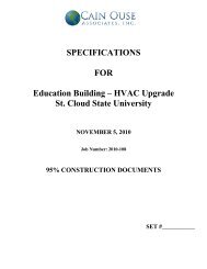
DIVISIONS 21, 22 & 23 - TITLE PAGE<br />
SPECIFICATIONS<br />
FOR THE<br />
CONSTRUCTION OF<br />
SAINT CLOUD STATE UNIVERSITY<br />
EDUCATION BUILDING HVAC UPGRADE PROJECT<br />
ST. CLOUD, MINNESOTA<br />
CAIN OUSE ASSOCIATES, INC.<br />
PROJECT NUMBER 2010-108<br />
I hereby certify that this plan, specification or report was prepared by me, or under my<br />
direct supervision, and that I am a duly Licensed Professional Engineer under the laws<br />
of the State of Minnesota.<br />
Name<br />
SCOTT D. THOMAS, P.E.<br />
Signature<br />
Date: NOVEMBER 5, 2010 (<strong>95%</strong> SUBMITTAL Registration No. 21659
BLANK PAGE
MECHANICAL SPECIFICATIONS INDEX<br />
FIRE PROTECTION<br />
21 01 00 FIRE PROTECTION GENERAL PROVISIONS<br />
21 13 00 FIRE PROTECTION<br />
PLUMBING<br />
22 01 00 PLUMBING GENERAL PROVISIONS<br />
22 01 10 PLUMBING SYSTEMS TESTING<br />
22 05 00 PLUMBING BASIC PRODUCTS AND METHODS<br />
22 07 00 PLUMBING SYSTEMS INSULATION<br />
22 11 00 DOMESTIC BUILDING WATER SYSTEMS<br />
22 13 00 SOIL AND WASTE PIPING SYSTEMS<br />
22 42 00 PLUMBING FIXTURES<br />
HEATING, VENTILATING AND AIR CONDITIONING<br />
23 01 00 HVAC GENERAL PROVISIONS<br />
23 05 00 HVAC BASIC PRODUCTS AND METHODS<br />
23 05 40 MECHANICAL SOUND AND VIBRATION CONTROL<br />
23 05 90 TESTING, ADJUSTING AND BALANCING<br />
23 07 00 HVAC SYSTEMS INSULATION<br />
23 08 00 HVAC SYSTEMS COMMISSIONING<br />
23 09 00 AUTOMATIC TEMPERATURE CONTROL<br />
23 21 00 HYDRONIC PIPING SYSTEMS<br />
23 21 20 HYDRONIC SYSTEMS EQUIPMENT<br />
23 31 00 AIR DISTRIBUTION DUCT SYSTEM<br />
23 31 90 DUCTWORK CLEANING<br />
23 34 00 AIR DISTRIBUTION EQUIPMENT<br />
SCSU <strong>Education</strong> <strong>Building</strong> HVAC Upgrade Project<br />
Cain Ouse Associates, Inc.<br />
Project Number 2010-108
SCSU <strong>Education</strong> <strong>Building</strong> HVAC Upgrade Project<br />
Cain Ouse Associates, Inc.<br />
Project Number 2010-108<br />
BLANK PAGE
CAIN OUSE ASSOCIATES, INC.<br />
PROJECT NUMBER 2010-108<br />
SAINT CLOUD STATE UNIVERSITY<br />
EDUCATION BUILDING HVAC UPGRADE PROJECT<br />
SECTION 21 0100<br />
FIRE PROTECTION GENERAL PROVISIONS<br />
PART 1<br />
REFERENCE<br />
1.01 GENERAL<br />
A. Division 00 Conditions of the Contract and Division 01 General Requirements are hereby<br />
made a part of this division.<br />
B. All reference to Fire Protection Work or Division 21 in other Divisions are hereby made a<br />
part of this division.<br />
C. Division 21 work shall include all Fire Protection work referenced in other Divisions of the<br />
work unless explicitly indicated otherwise.<br />
D. If any statements contained in Division 21 should conflict with the conditions of the<br />
contract or the General Requirements, the statement requiring the greater quantity,<br />
superior quality, or condition most favorable to the owner shall take precedence.<br />
E. If any statements contained in Division 21 conflict within the other Divisions of the work,<br />
the statement requiring the greater quantity, superior quality, or condition most favorable<br />
to the owner shall take precedence.<br />
F. Where words fire protection contract(s), fire protection contractor, fire protection, fire<br />
protection work, sprinkler contractor, sprinkler contract, sprinkler or sprinkler work appear<br />
in contract documents, that shall be taken to mean or refer to contracts or subcontracts<br />
for plumbing work required as scope of Division 21 work.<br />
G. Contract drawings show arrangements and sizes of principal apparatus and devices to<br />
be provided under this contract and connections thereto. These shall be followed as<br />
closely as actual building construction will permit.<br />
H. Drawings are diagrammatic and are a graphic representation of contract requirements,<br />
produced according to best available standards to an optimum scale. Dimensions of<br />
work as indicated on plans are not guaranteed to be as-built dimensions. No<br />
measurements shall be scaled from drawings and used as a definite dimension for layout<br />
or fitting work in place.<br />
I. Dimensions and ratings of equipment herein specified or indicated on drawings are<br />
indicated to establish desired outlines and characteristics of such equipment. Minor<br />
deviations will be permitted to allow manufactures specified to bid on their nearest stock<br />
equipment providing that substituted equipment equals or exceeds the basic<br />
performance conditions indicated. Contractor making substitution shall pay any<br />
increments costs incurred; contractor shall bear all costs of modifying substituted product<br />
to fit conditions shown or modifying building or other systems to receive product.<br />
HVAC UPGRADE PROJECT 210100 - 1 of 8 FIRE PROTECTION GENERAL PROVISIONS
SAINT CLOUD STATE UNIVERSITY<br />
CAIN OUSE ASSOCIATES, INC.<br />
EDUCATION BUILDING HVAC UPGRADE PROJECT PROJECT NUMBER 2010-108<br />
J. The mechanical reference symbols used on the drawings refer to the symbol sheets on<br />
the drawings or bound herein. These symbols shall designate materials, type, line<br />
descriptions and valve types for use on this project.<br />
K. Give careful consideration to work by all contractors on the job and organize the work so<br />
that it will not interfere with work of other trades. Consult the drawings and specifications<br />
for work to be provided by other trades for correlating information, and the architectural<br />
and structural drawings for details, dimensions, foundations, pits, etc. The contractor<br />
shall verify all dimensions and conditions before starting their work.<br />
L. Manufactured material hereinafter specified or shown on drawings shall be installed or<br />
applied according to manufacturers' directions unless specifically designated otherwise.<br />
M. Provide shall be defined as furnish and install. Therefore, where documents call for this<br />
division of the work to provide a certain item, this contractor shall be responsible for<br />
furnishing and installing that item.<br />
1.02 WORK INCLUDED<br />
A. Work includes furnishing all labor, material, equipment, service and the completion of<br />
details not mentioned or shown which are necessary for and reasonable incidental to<br />
successful operation of all mechanical systems as shown on drawings and as specified,<br />
except as such items as are specifically noted as being furnished under other sections of<br />
specifications.<br />
B. Drawings and specifications are to be considered as supplementing each other. Work<br />
specified but not shown, or shown but not specified, shall be performed or furnished as<br />
though mentioned in both specifications and drawings.<br />
C. Minor items, accessories or devices reasonably inferable as necessary for completion<br />
and proper operation of any system shall be provided by contractor or subcontractor for<br />
such system whether or not specifically called for by specifications or drawings.<br />
D. The only fire protection work not included shall be those items explicitly indicated<br />
otherwise.<br />
E. Layout of equipment as shown on drawings shall be checked and exact locations<br />
determined from dimensions or equipment approved by engineer. Adequate space for<br />
operation and maintenance shall be maintained.<br />
1.03 EXAMINATION OF DOCUMENTS<br />
A. Carefully read the project drawings and project specifications before submitting bid on<br />
the work to be done. Any doubt as to the true meaning of any part of the project<br />
specifications or other proposed contract documents shall be submitted in writing to the<br />
engineer for an interpretation thereof.<br />
B. The person submitting the request will be responsible for its prompt delivery.<br />
C. Interpretation of the proposed contract documents will be made only in writing duly<br />
issued, a copy of which will be mailed or delivered to each bidder receiving a copy of the<br />
FIRE PROTECTION GENERAL PROVISIONS 210100 - 2 of 8 HVAC UPGRADE PROJECT
CAIN OUSE ASSOCIATES, INC.<br />
PROJECT NUMBER 2010-108<br />
SAINT CLOUD STATE UNIVERSITY<br />
EDUCATION BUILDING HVAC UPGRADE PROJECT<br />
project drawings and project manual and to such other prospective bidders as have<br />
requested they be furnished with a copy of each.<br />
1.05 SUBSTITUTE MATERIAL<br />
A. Requirements Division 0 Conditions of the Contract and Division I General Requirements<br />
apply to this article.<br />
B. If contractors wish to use item of equipment and/or materials other than those named in<br />
specification, apply in writing to the architect/engineer for approval of substitution prior to<br />
opening of bids, submitting with request for approval complete, descriptive and technical<br />
data on the items or item proposed to be furnished. Prior approval period shall be as<br />
indicated in the General Conditions.<br />
C. System design is based on first manufacturer mentioned. Additional listed manufacturers<br />
may be used in the base bid provided that this division of the work assumes responsibility<br />
for correct size and capacity, space limitations, plumbing and electrical deviations. This<br />
responsibility to include any redesign of the structure, foundations, utilities, piping, wiring<br />
or any other part of the structural, mechanical, sanitary or electrical work. The cost of all<br />
such redesign, drawings, detailing and accompanying additional costs of any such items<br />
of the work, shall be paid by this section of the work and such redesign shall be subject<br />
to the approval of the engineer.<br />
1.06 GUARANTEES<br />
A. Requirements of Division 00 Conditions of the Contract and Division 01 General<br />
Requirements apply to this article.<br />
B. This contractor is responsible for any defects which may develop in any part of the<br />
mechanical systems, caused by faulty workmanship, material or equipment, and shall<br />
agree to replace any such faulty workmanship, material or equipment during the period of<br />
one year from date of substantial completion of the work without cost to owner.<br />
Acceptance of this work shall not waive this guarantee.<br />
1.07 CODES AND STANDARDS<br />
A. The mechanical design is intended to conform with all local codes, including the<br />
applicable requirements of the latest edition of the following standards and/or regulations.<br />
All material and equipment must conform to these codes. This shall not permit a lower<br />
grade of construction where the drawings or specifications call for workmanship or<br />
materials in excess of code requirements.<br />
International <strong>Building</strong> Code with State of Minnesota Amendments<br />
International Fire Code<br />
State of Minnesota Plumbing Code<br />
Iternational <strong>Mechanical</strong> Code with State of Minnesota Amendments<br />
State of Minnesota Energy Code<br />
Local Codes<br />
American Concrete Institute<br />
American Conference of Governmental Industrial Hygienists<br />
American Institute of Steel Construction<br />
HVAC UPGRADE PROJECT 210100 - 3 of 8 FIRE PROTECTION GENERAL PROVISIONS
SAINT CLOUD STATE UNIVERSITY<br />
CAIN OUSE ASSOCIATES, INC.<br />
EDUCATION BUILDING HVAC UPGRADE PROJECT PROJECT NUMBER 2010-108<br />
American Gas Association<br />
Institute of Electrical and Electronic Engineers<br />
American Society of <strong>Mechanical</strong> Engineers<br />
American Society of Testing Materials<br />
American Standards Association<br />
American National Standard Institute<br />
Sheet Metal, Air Conditioning and Roofing Contractors Association<br />
American Welding Society<br />
National Board of Fire Underwriters<br />
National Fire Protection Association<br />
National Bureau of Standards<br />
National Electric Code<br />
National Electrical Manufacturers Association<br />
National Sanitation Foundation<br />
American Air Balance Council<br />
American Society of Heating, Refrigeration and Air Conditioning Engineers<br />
National Safety Code for <strong>Mechanical</strong> Refrigeration<br />
National Association of Sheet Metal and Air Conditioning Engineers<br />
Environmental Protection Agency<br />
Pollution Control Agency<br />
Occupational Safety and Health Act<br />
1.08 FEES AND PERMITS<br />
A. All fees, permits and licenses required for the mechanical work are to be included in the<br />
contract. Fees shall also include Plan Review Fees required by the State.<br />
B. Any inspection charges by governing authorities shall be requested and paid for under<br />
this contract.<br />
1.09 Submittals<br />
A. Division 01 General Requirements shall apply to this Division of the Contract.<br />
B. Submit shop drawings for the following equipment and materials:<br />
Valves<br />
Piping and Associated Specialties<br />
Hangers, Supports and Anchors<br />
Sprinkler Heads<br />
Piping Identification<br />
FM 200 Systems<br />
Miscellaneous Specialties<br />
C. Refer to individual specification sections for additional specific requirements.<br />
D. Submit job tailored piping diagrams for equipment with unit mounted piping systems.<br />
E. Submit job tailored wiring diagrams for equipment with unit mounted control systems.<br />
F. See other Division 21 Sections for further requirements.<br />
FIRE PROTECTION GENERAL PROVISIONS 210100 - 4 of 8 HVAC UPGRADE PROJECT
CAIN OUSE ASSOCIATES, INC.<br />
PROJECT NUMBER 2010-108<br />
SAINT CLOUD STATE UNIVERSITY<br />
EDUCATION BUILDING HVAC UPGRADE PROJECT<br />
PART 2<br />
PRODUCTS<br />
NOT APPLICABLE<br />
PART 3<br />
EXECUTION<br />
3.01 CUTTING AND PATCHING<br />
A. All cutting, fitting, repairing, and finishing of carpentry work, metal work or concrete work,<br />
etc., which may be required for the work installed under this division, shall be done by<br />
workers skilled in their respective trades at the expense of this contractor. When cutting<br />
is required, it shall be done in such a manner as not to weaken walls, partitions or floors<br />
and holes required to be cut in floors must be drilled without breaking out around the<br />
holes. The contractor shall make arrangements with the trades to do all work covered by<br />
their respective trades.<br />
B. Before doing any cutting, the contractor shall obtain permission from the engineer and<br />
follow engineer's instructions as to the method of cutting. All holes shall be cut as small<br />
as possible to admit piping and with as much care as possible. This shall include cutting<br />
of all floors that are poured where sleeves or openings are omitted.<br />
C. Avoid cutting insofar as possible by setting sleeves, frames, etc., or requesting openings<br />
in advance.<br />
D. Assist general contractor in framing openings for ducts and/or piping by checking location<br />
of openings required and checking sizes of openings required.<br />
E. If cutting of existing work or newly furnished work is required by the contractor, contractor<br />
is responsible for the work to its original condition.<br />
3.02 TEMPORARY WATER AND SEWER<br />
A. Carefully examine all parts of Division 00 Conditions of the Contract, and Division 01<br />
General Requirements for requirements regarding temporary sewer, water, gas, etc.<br />
Each contractor shall provide for these requirements.<br />
3.03 ENTRY OF EQUIPMENT<br />
A. Make all provisions for the entry of equipment provided under contract to the installed<br />
locations. Provide all openings in the building, if necessary, and do all excavating,<br />
backfilling and repair necessary.<br />
3.04 CONNECTIONS AND LAYOUT<br />
A. Piping and equipment shall be installed substantially as shown on the drawings. Exact<br />
location of each and every pipe and piece of equipment cannot be given by scaling the<br />
drawings, but shall in every case be placed so as to avoid interference with other work.<br />
Should it be necessary to make minor changes in the location of any pipe or piece of<br />
HVAC UPGRADE PROJECT 210100 - 5 of 8 FIRE PROTECTION GENERAL PROVISIONS
SAINT CLOUD STATE UNIVERSITY<br />
CAIN OUSE ASSOCIATES, INC.<br />
EDUCATION BUILDING HVAC UPGRADE PROJECT PROJECT NUMBER 2010-108<br />
equipment for its proper installation and operation, or to avoid conflict with other trades, it<br />
shall be done by the contractor without extra cost.<br />
B. Where connections are made to equipment furnished by others, the contractor shall<br />
obtain exact location of connection from persons furnishing said equipment.<br />
C. Pipes shall be run with proper grade to provide for easy draining. Pipes must be<br />
thoroughly reamed and cleaned before installation. Consult and cooperate fully with the<br />
other contractors so as to obtain the proper grouping of pipes and to avoid interference.<br />
Pipes run overhead shall be placed as close to the ceiling structure as possible to<br />
maintain proper headroom and to present a neat appearance, all consistent with the<br />
correct pitching of pipes. Consult the engineer before installing any pipe lines or<br />
ductwork which will reduce the proper headroom or ceiling in any way. Piping shall be<br />
run as shown on the drawings, but the engineer reserves the right to make slight<br />
changes, without extra charge, to avoid interference with other work or unforeseen<br />
structural interference.<br />
3.05 CLEANING AND HOUSEKEEPING<br />
A. Requirements of Division 00 Conditions of the Contract, and Division 01 General<br />
Requirements apply to this article.<br />
B. Each contractor shall clear away all debris, surplus materials, etc., resulting from the<br />
work or operation, leaving the job and the equipment furnished under the contract in a<br />
clean condition.<br />
C. Fixtures and equipment shall be thoroughly cleaned, removing all plaster, paint, stickers,<br />
rust, stains, and other foreign matter or discolorations, leaving every part in an<br />
acceptable condition and ready for use.<br />
3.06 IDENTIFICATION<br />
A. The fire protection contractor shall be responsible for and provide the identification and<br />
labeling of all equipment and piping. All identification shall conform to the requirements<br />
of the International <strong>Mechanical</strong> Code and as follows:<br />
1. Label all lines using Seton Company or equal prepared label, or the stencil<br />
method with black lettering on all light colored lines and white lettering on all dark<br />
colored lines.<br />
2. Pipe Labeling Locations:<br />
a) Whenever a pipe turns 90 degrees out of sight from identification.<br />
b) Wherever a pipe passes through a wall, bands shall occur close to the<br />
wall on both sides.<br />
c) In all other locations deemed necessary by architect/engineer for ease of<br />
maintenance.<br />
d) At no more than 25 foot intervals.<br />
3. Adjacent to each color band or set of bands, the function of the particular pipe<br />
and an arrow denoting the direction of flow shall be stenciled in black. Stenciled<br />
letters shall be a minimum of 1" high and along with the arrow, shall be applied in<br />
FIRE PROTECTION GENERAL PROVISIONS 210100 - 6 of 8 HVAC UPGRADE PROJECT
CAIN OUSE ASSOCIATES, INC.<br />
PROJECT NUMBER 2010-108<br />
SAINT CLOUD STATE UNIVERSITY<br />
EDUCATION BUILDING HVAC UPGRADE PROJECT<br />
3.07 PAINTING<br />
a position that is easily read from the normal location of personnel within the<br />
space.<br />
4. Equipment shall be identified with 1" high letters indicating unit abbreviation and<br />
number. For example, water heaters shall be identified as WH-1 and WH-2.<br />
A. This Contractor shall do no painting except as hereinafter specified.<br />
3.08 ELECTRICAL<br />
1. This contractor shall paint all unpainted brackets, stands, supports, etc., with one<br />
coat of Rust-Oleum metal primer and one coat of Rust-Oleum grey paint.<br />
A. This section includes all electrical wiring systems for the mechanical work as hereinafter<br />
described. Furnish and set in place all motors required for the operation of equipment<br />
furnished in this contract.<br />
B. All electrical and motor characteristics shall be as shown on the electrical and<br />
mechanical drawings or specifications.<br />
C. Electrical contractor will furnish all disconnects and starters as required for all motors,<br />
unless noted otherwise.<br />
D. Unless indicated otherwise, the electrical contractor will mount the disconnects and<br />
starters and will wire through the disconnect, through the starter and make connections<br />
to motors unless mounted and wired as part of package equipment.<br />
E. Unless indicated otherwise, all control devices and all control wiring required for the<br />
proper operation of all plumbing equipment shall be furnished and installed complete by<br />
this contractor.<br />
F. Motor control wiring done by this contractor shall conform to the requirements of the<br />
Electrical <strong>Specifications</strong>.<br />
G. Changes to the electrical system necessitated by equipment, motors, etc., furnished by<br />
this contractor that differ from those specified shall be paid for by this contractor.<br />
H. Single phase motors shall be permanent split capacitor type, drip-proof. Three phase<br />
motors general purpose, squirrel cage induction type unless specified otherwise.<br />
Minimum service factors shall be 1.15. All motors single speed, 1750 RPM, unless<br />
specified otherwise for specific equipment.<br />
I. All three phase motors for mechanical equipment rated 3 horsepower and larger shall be<br />
high efficiency type. Motors shall be labeled to comply with NEMA Standard MG1-12.53<br />
with the nominal efficiency printed on the nameplate. Efficiency shall be based on<br />
dynamometer testing per IEEE, Standard 112, Method B. Motors shall be equivalent to<br />
Delco E2, Ground-Century, E-Plus, G.E. Energy Saver, Reliance XE or Westinghouse<br />
Lifeline Tee II.<br />
HVAC UPGRADE PROJECT 210100 - 7 of 8 FIRE PROTECTION GENERAL PROVISIONS
SAINT CLOUD STATE UNIVERSITY<br />
CAIN OUSE ASSOCIATES, INC.<br />
EDUCATION BUILDING HVAC UPGRADE PROJECT PROJECT NUMBER 2010-108<br />
J. Wiring work by this Division of the Work shall be performed in accordance with the<br />
requirements of the Division 16 <strong>Specifications</strong> and the latest edition of the National<br />
Electric Code.<br />
3.09 TRAINING<br />
A. Prior to on-site training, provide classroom training at a site approved by the Owner.<br />
B. Provide additional on site training to walk through start-up, shut down and preventative<br />
maintenance procedures.<br />
C. Provide additional on site training at the time of final completion to refresh the owner on<br />
the proper operation of the system.<br />
D. Training shall be video taped with the video tape furnished to the Owner.<br />
E. Contractor shall coordinate training between equipment suppliers and the Owner so the<br />
equipment suppliers actually perform the training.<br />
END OF SECTION<br />
FIRE PROTECTION GENERAL PROVISIONS 210100 - 8 of 8 HVAC UPGRADE PROJECT
CAIN OUSE ASSOCIATES, INC.<br />
PROJECT NUMBER 2010-108<br />
SAINT CLOUD STATE UNIVERSITY<br />
EDUCATION BUILDING HVAC UPGRADE PROJECT<br />
SECTION 21 1300<br />
FIRE PROTECTION<br />
PART 1<br />
GENERAL<br />
1.01 REFERENCE<br />
A. Requirements of Section 210100 General Provisions apply to all work under this section.<br />
1.02 SCOPE<br />
A. This section includes all labor, material, equipment, skill and tools necessary to furnish<br />
and install the sprinkler piping, sprinkler risers, and sprinklers from five feet outside of the<br />
building.<br />
B. The installation shall comply with all local rules and regulations and with all rules and<br />
regulations of the National fire Protection Association #13, #20, #24, #231, #231C, and<br />
#291.<br />
C. Separate domestic and fire services shall be provided as shown on the plans.<br />
D. Areas subject to freezing shall be provided with a dry system. Dry pipe valves shall be<br />
located at the water service or as noted.<br />
E. Provide stand-pipe systems in the Stairwells in accordance with NFPA 14, City of St.<br />
Cloud requirements and State of Minnesota requirements.<br />
F. Zoning: provide one zone per floor complete with isolation valve (with tamper switch) and<br />
flow switch for each floor level. Floor zone valve assemblies shall be located in the<br />
Lower Level <strong>Mechanical</strong> Room at location shown on the plans.<br />
1.03 QUALIFICATIONS OF CONTRACTOR<br />
A. The contractor for this fire protection installation shall be a duly licensed and qualified fire<br />
protection contractor, and regularly engaged in the installation of automatic sprinkler<br />
systems.<br />
1.04 WORKING DRAWINGS<br />
A. Before commencing fire protection installation, the fire protection contractor shall submit<br />
installation drawings and hydraulic calculations to the local fire marshal and the owner's<br />
insurance company for approval. Installation drawings and hydraulic calculations shall<br />
be certified by a Minnesota Registered Professional Engineer.<br />
B. The installation drawings shall be coordinated with the work of other trades to avoid<br />
conflict with conduit, lights, piping, mechanical equipment, and structural elements.<br />
C. After fire marshal and insurance company approval, the sprinkler contractor shall submit<br />
the working drawings and hydraulic calculations to the architect and shall secure agency<br />
HVAC UPGRADE PROJECT 231300 - 1 of 4 FIRE PROTECTION
SAINT CLOUD STATE UNIVERSITY<br />
CAIN OUSE ASSOCIATES, INC.<br />
EDUCATION BUILDING HVAC UPGRADE PROJECT PROJECT NUMBER 2010-108<br />
approvals before commencing work at the job site. Copies of installation approval letters<br />
or certificates shall be delivered by sprinkler contractor to architect at completion of work.<br />
D. Professional Liability/Errors & Omissions Insurance: At the time of Shop Drawing<br />
Submittal, submit a Certificate of the Professional Liability/Errors and Omissions<br />
Insurance. Contractor shall carry Engineer’s Professional Liability insurance policy<br />
coverage with a $1,000,000.00 limit for each occurrence and $2,000,000.00 annual<br />
aggregate coverage.<br />
1.05 SPRINKLER DENSITIES<br />
A. Densities indicated herein are minimum requirements. The owner's insurance company,<br />
NFPA and local requirements that mandate greater densities shall prevail.<br />
B. Sprinkler system serving office and classroom areas shall be hydraulically designed for<br />
.10 GPM per square foot over the most remote 1500 square feet (Light Hazard) with 100<br />
GPM hose stream.<br />
C. Sprinkler system serving storage rooms/areas and mechanical spaces shall be<br />
hydraulically designed for .15 GPM per square foot over the most remote 1500 square<br />
feet (Ordinary Hazard Group I) with 250 GPM hose stream.<br />
1.06 HYDRAULIC DESIGN BASIS<br />
A. Provide system design and hydraulic calculation based on water flow test as specified in<br />
this Section of the Specification.<br />
1.07 WATER FLOW TEST<br />
A. A water flow test was performed on July 27, 2010 that yielded a static pressure of 63 psig<br />
and a residual pressure of 60 psig with a flow rate of 3570 gpm. The test hydrants were<br />
located east of the <strong>Education</strong> building and west of the Engineering <strong>Building</strong>. The flow<br />
hydrant was located directly in front of the Engineering <strong>Building</strong> and the test hydrant was<br />
located southwest of the Engineering <strong>Building</strong>.<br />
PART 2<br />
MATERIALS AND INSTALLATION<br />
2.01 MATERIALS, EQUIPMENT, VALVES AND DEVICES<br />
A. All materials, equipment valves and devices installed and/or furnished under this section<br />
shall be listed and/or approved for use in fire protection installation by the authorities,<br />
agencies, codes, and standards named in this section of the specifications.<br />
B. Backflow Prevention: As a minimum, provide a Detector Check Valve Assembly in<br />
accordance with the requirements of the State of Minnesota Plumbing Code.<br />
FIRE PROTECTION 211300 - 2 of 4 HVAC UPGRADE PROJECT
CAIN OUSE ASSOCIATES, INC.<br />
PROJECT NUMBER 2010-108<br />
SAINT CLOUD STATE UNIVERSITY<br />
EDUCATION BUILDING HVAC UPGRADE PROJECT<br />
2.02 PERMITS AND FEES<br />
A. Any permits or fees for the installation or construction of any portion of the automatic<br />
sprinkler system which are required by any of the authorities and/or agencies having<br />
jurisdiction, shall be obtained and paid for by this contractor.<br />
2.03 SPRINKLER HEADS<br />
A. Sprinkler heads shall be U.L. listed, 1/2" orifice and 165 degrees F. rated. Sprinkler<br />
heads located in the computer room shall be high temperature 212 degrees F. rated.<br />
Sprinkler heads installed are to be sidewall, upright or pendant as conditions require and<br />
shall be one of the following types and finishes:<br />
1. Upright sprinklers with plain brass finish in rooms without ceilings.<br />
2. Sidewall type sprinklers throughout room areas with finished ceilings shall be<br />
chrome plated complete with escutcheon plates.<br />
3. Finished areas with ceilings shall be provided with fully/semi-recessed pendent<br />
type heads and escutcheons of white finish.<br />
4. Sprinkler heads shall be quick response type where required by Code.<br />
B. Furnish spare sprinkler heads as required by NFPA.<br />
2.04 NUMBER OF SPRINKLER HEADS<br />
A. The contractor shall provide engineering drawings showing risers, cross main, branch<br />
main spacing, zones and head location and quantity. If more or less heads are required<br />
to obtain agency approval, the contract price will not be adjusted. The fewer or additional<br />
heads will be considered incidental to the installation.<br />
B. Provide wet sprinkler system complete with fire department connection.<br />
2.05 ALARM DEVICES<br />
A. Riser waterflow alarm switches to be Automatic Sprinkler Corporation Model 86-100, 15<br />
amp or approved equal and 10", 120 volt alarm bells on the outside wall and inside wall<br />
of the building and one 125 volt flashing beacon on outside wall all located where<br />
approved by local fire marshall. Connect to adjacent 120 volt circuit provided by Division<br />
16.<br />
B. Provide tamper switches for valves as indicated on the plans.<br />
2.06 FIRE DEPARTMENT CONNECTION<br />
A. Provide fire department Siamese connection as indicated on the plans. Fire department<br />
connection shall be Elkhart #156 or approved equal, polished brass wall type with 2 1/2"<br />
X 2 1/2" X 4" body and escutcheon in accordance with local fire department<br />
requirements.<br />
2.07 DRAINS<br />
A. System drains shall be discharged to the outside of the building.<br />
HVAC UPGRADE PROJECT 231300 - 3 of 4 FIRE PROTECTION
SAINT CLOUD STATE UNIVERSITY<br />
CAIN OUSE ASSOCIATES, INC.<br />
EDUCATION BUILDING HVAC UPGRADE PROJECT PROJECT NUMBER 2010-108<br />
2.08 STANDPIPES<br />
A. Provide Class I standpipes where shown on plans.<br />
PART 3<br />
EXECUTION<br />
3.01 GUARANTEE<br />
A. The entire fire protection installation, as specified under this section of the specifications,<br />
shall be guaranteed for one (1) year against defective equipment, materials and<br />
workmanship. The guarantee period is to begin on the date the equipment is placed in<br />
operation at the owner's request or for owner's convenience, or from the date a<br />
successful acceptance test is made, whichever occurs first.<br />
B. This guarantee shall not be construed to render service or maintenance required in the<br />
normal operation of the equipment, or to make repairs that may be needed due to normal<br />
wear and tear or the owner's negligence, abuse or breakage.<br />
3.02 SYSTEM CLEANING AND TESTS<br />
A. Flush system of foreign matter in accordance with NFPA 13.<br />
B. At completion of installation, hydrostatically test system in accordance with NFPA 13.<br />
C. Test shall be witness by Fire Marshal, owner and/or architect/engineer.<br />
3.03 INSTALLATION<br />
A. Place pipe runs to minimize obstruction to other work.<br />
B. Where ceilings will exist, place piping in concealed spaces above finished ceilings.<br />
C. Sprinkler heads in areas with finished ceilings shall be installed such that in a ceiling grid,<br />
heads shall not be any closer than 1'-0" from any side of the ceiling tile (a tolerance of +<br />
or - of one inch will be allowed). Where necessary, relocate existing sprinkler heads to<br />
avoid new ceiling heights and light fixtures.<br />
END OF SECTION<br />
FIRE PROTECTION 211300 - 4 of 4 HVAC UPGRADE PROJECT
CAIN OUSE ASSOCIATES, INC.<br />
PROJECT NUMBER 2010-108<br />
SAINT CLOUD STATE UNIVERSITY<br />
EDUCATION BUILDING HVAC UPGRADE PROJECT<br />
SECTION 22 0100<br />
PLUMBING GENERAL PROVISIONS<br />
PART 1<br />
REFERENCE<br />
1.01 GENERAL<br />
A. Division 00 Conditions of the Contract and Division 01 General Requirements are hereby<br />
made a part of this division.<br />
B. All reference to plumbing work or Division 22 in other Divisions are hereby made a part of<br />
this division.<br />
C. Division 22 work shall include all mechanical work referenced in other Divisions of the<br />
work unless explicitly indicated otherwise.<br />
D. If any statements contained in Division 22 should conflict with the conditions of the<br />
contract or the General Requirements, the statement requiring the greater quantity,<br />
superior quality, or condition most favorable to the owner shall take precedence.<br />
E. If any statements contained in Division 22 conflict within the other Divisions of the work,<br />
the statement requiring the greater quantity, superior quality, or condition most favorable<br />
to the owner shall take precedence.<br />
F. Where words "plumbing contract(s)", "plumbing contractor", "plumbing" or "plumbing<br />
work" appear in contract documents, that shall be taken to mean or refer to contracts or<br />
subcontracts for plumbing work required as scope of Division 22 work.<br />
G. Contract drawings show arrangements and sizes of principal apparatus and devices to<br />
be provided under this contract and connections thereto. These shall be followed as<br />
closely as actual building construction will permit.<br />
H. Drawings are diagrammatic and are a graphic representation of contract requirements,<br />
produced according to best available standards to an optimum scale. Dimensions of<br />
work as indicated on plans are not guaranteed to be as-built dimensions. No<br />
measurements shall be scaled from drawings and used as a definite dimension for layout<br />
or fitting work in place.<br />
I. Dimensions and ratings of equipment herein specified or indicated on drawings are<br />
indicated to establish desired outlines and characteristics of such equipment. Minor<br />
deviations will be permitted to allow manufactures specified to bid on their nearest stock<br />
equipment providing that substituted equipment equals or exceeds the basic<br />
performance conditions indicated. Contractor making substitution with prior approved<br />
products shall pay any increments costs incurred; contractor shall bear all costs of<br />
modifying substituted product to fit conditions shown or modifying building or other<br />
systems to receive product.<br />
HVAC UPGRADE PROJECT 220100 - Page 1 of 10 PLUMBING GENERAL PROVISIONS
SAINT CLOUD STATE UNIVERSITY<br />
CAIN OUSE ASSOCIATES, INC.<br />
EDUCATION BUILDING HVAC UPGRADE PROJECT PROJECT NUMBER 2010-108<br />
J. The mechanical reference symbols used on the drawings refer to the symbol sheets on<br />
the drawings or bound herein. These symbols shall designate materials, type, line<br />
descriptions and valve types for use on this project.<br />
K. Give careful consideration to work by all contractors on the job and organize the work so<br />
that it will not interfere with work of other trades. Consult the drawings and specifications<br />
for work to be provided by other trades for correlating information, and the architectural<br />
and structural drawings for details, dimensions, foundations, pits, etc. The contractor<br />
shall verify all dimensions and conditions before starting their work.<br />
L. Manufactured material hereinafter specified or shown on drawings shall be installed or<br />
applied according to manufacturers' directions unless specifically designated otherwise.<br />
M. Provide shall be defined as furnish and install. Therefore, where documents call for this<br />
division of the work to provide a certain item, this contractor shall be responsible for<br />
furnishing and installing that item.<br />
N. Where the documents refer to “approved equal”, it shall mean “prior approved equal”.<br />
Manufacturers must be approved prior to the closing of the bids to be allowed on the<br />
project. Manufacturers must be indicated by name in the project manual, on the<br />
drawings or in the Addenda to be allowed on the project.<br />
1.02 WORK INCLUDED<br />
A. Work includes furnishing all labor, material, equipment, service and the completion of<br />
details not mentioned or shown which are necessary for and reasonable incidental to<br />
successful operation of all mechanical systems as shown on drawings and as specified,<br />
except as such items as are specifically noted as being furnished under other sections of<br />
specifications.<br />
B. Drawings and specifications are to be considered as supplementing each other. Work<br />
specified but not shown, or shown but not specified, shall be performed or furnished as<br />
though mentioned in both specifications and drawings.<br />
C. Minor items, accessories or devices reasonably inferable as necessary for completion<br />
and proper operation of any system shall be provided by contractor or subcontractor for<br />
such system whether or not specifically called for by specifications or drawings.<br />
D. The only mechanical work not included shall be those items explicitly indicated otherwise.<br />
E. Layout of equipment as shown on drawings shall be checked and exact locations<br />
determined from dimensions or equipment approved by engineer. Adequate space for<br />
operation and maintenance shall be maintained.<br />
1.03 EXAMINATION AND LOCATION OF SITE<br />
A. Visit the building site and become familiar with all the existing conditions before<br />
submitting bid. Failure to visit site will in no way relieve the contractor from necessity of<br />
furnishing any material or performing any work that may be required to complete the work<br />
in accordance with the drawings and specifications which could be only determined by<br />
visiting the site.<br />
PLUMBING GENERAL PROVISIONS 220100 - Page 2 of 10 HVAC UPGRADE PROJECT
CAIN OUSE ASSOCIATES, INC.<br />
PROJECT NUMBER 2010-108<br />
SAINT CLOUD STATE UNIVERSITY<br />
EDUCATION BUILDING HVAC UPGRADE PROJECT<br />
1.04 EXAMINATION OF DOCUMENTS<br />
A. Carefully read the project drawings and project specifications before submitting bid on<br />
the work to be done. Any doubt as to the true meaning of any part of the project<br />
specifications or other proposed contract documents shall be submitted in writing to the<br />
engineer for an interpretation thereof.<br />
B. The person submitting the request will be responsible for its prompt delivery.<br />
C. Interpretation of the proposed contract documents will be made only in writing duly<br />
issued, a copy of which will be mailed or delivered to each bidder receiving a copy of the<br />
project drawings and project manual and to such other prospective bidders as have<br />
requested they be furnished with a copy of each.<br />
1.05 SUBSTITUTE MATERIAL<br />
A. Requirements Division 0 Conditions of the Contract and Division I General Requirements<br />
apply to this article.<br />
B. If contractors wish to use item of equipment and/or materials other than those named in<br />
specification, apply in writing to the architect/engineer for approval of substitution prior to<br />
opening of bids, submitting with request for approval complete, descriptive and technical<br />
data on the items or item proposed to be furnished. Prior approval period shall be as<br />
indicated in the General Conditions.<br />
C. System design is based on first manufacturer mentioned. Additional listed manufacturers<br />
may be used in the base bid provided that this division of the work assumes responsibility<br />
for correct size and capacity, space limitations, plumbing and electrical deviations. This<br />
responsibility to include any redesign of the structure, foundations, utilities, piping, wiring<br />
or any other part of the structural, mechanical, sanitary or electrical work. The cost of all<br />
such redesign, drawings, detailing and accompanying additional costs of any such items<br />
of the work, shall be paid by this section of the work and such redesign shall be subject<br />
to the approval of the engineer.<br />
1.06 GUARANTEES<br />
A. Requirements of Division 00 Conditions of the Contract and Division 01 General<br />
Requirements apply to this article.<br />
B. This contractor is responsible for any defects which may develop in any part of the<br />
mechanical systems, caused by faulty workmanship, material or equipment, and shall<br />
agree to replace any such faulty workmanship, material or equipment during the period of<br />
one year from date of substantial completion of the work without cost to owner.<br />
Acceptance of this work shall not waive this guarantee.<br />
1.07 CODES AND STANDARDS<br />
A. The mechanical design is intended to conform with all local codes, including the<br />
applicable requirements of the latest edition of the following standards and/or regulations.<br />
All material and equipment must conform to these codes. This shall not permit a lower<br />
HVAC UPGRADE PROJECT 220100 - Page 3 of 10 PLUMBING GENERAL PROVISIONS
SAINT CLOUD STATE UNIVERSITY<br />
CAIN OUSE ASSOCIATES, INC.<br />
EDUCATION BUILDING HVAC UPGRADE PROJECT PROJECT NUMBER 2010-108<br />
grade of construction where the drawings or specifications call for workmanship or<br />
materials in excess of code requirements.<br />
International <strong>Building</strong> Code with State of Minnesota Amendments<br />
International Fire Code<br />
State of Minnesota Plumbing Code<br />
Iternational <strong>Mechanical</strong> Code with State of Minnesota Amendments<br />
State of Minnesota Energy Code<br />
Local Codes<br />
American Concrete Institute<br />
American Conference of Governmental Industrial Hygienists<br />
American Institute of Steel Construction<br />
American Gas Association<br />
Institute of Electrical and Electronic Engineers<br />
American Society of <strong>Mechanical</strong> Engineers<br />
American Society of Testing Materials<br />
American Standards Association<br />
American National Standard Institute<br />
Sheet Metal, Air Conditioning and Roofing Contractors Association<br />
American Welding Society<br />
National Board of Fire Underwriters<br />
National Fire Protection Association<br />
National Bureau of Standards<br />
National Electric Code<br />
National Electrical Manufacturers Association<br />
National Sanitation Foundation<br />
American Air Balance Council<br />
American Society of Heating, Refrigeration and Air Conditioning Engineers<br />
National Safety Code for <strong>Mechanical</strong> Refrigeration<br />
National Association of Sheet Metal and Air Conditioning Engineers<br />
Environmental Protection Agency<br />
Pollution Control Agency<br />
Occupational Safety and Health Act<br />
1.08 FEES AND PERMITS<br />
A. All fees, permits and licenses required for the mechanical work are to be included in the<br />
contract.<br />
B. Any inspection charges by governing authorities shall be requested and paid for under<br />
this contract.<br />
C. SAC and WAC (Sewer and Water Availability Charges) will be paid for by the Owner.<br />
D. Saint Cloud State University will pay for Plan Review Fees.<br />
1.09 Submittals<br />
A. Division 01 General Requirements shall apply to this Division of the Contract.<br />
PLUMBING GENERAL PROVISIONS 220100 - Page 4 of 10 HVAC UPGRADE PROJECT
CAIN OUSE ASSOCIATES, INC.<br />
PROJECT NUMBER 2010-108<br />
SAINT CLOUD STATE UNIVERSITY<br />
EDUCATION BUILDING HVAC UPGRADE PROJECT<br />
B. Submit shop drawings for the following equipment and materials:<br />
Valves<br />
Piping and Associated Specialties<br />
Hangers, Supports and Anchors<br />
Insulation Materials<br />
Plumbing Fixtures<br />
Floor Drains<br />
Clean Outs<br />
Piping Identification<br />
Vacuum Breakers and Backflow Preventers<br />
C. Refer to individual specification sections for additional specific requirements.<br />
D. Submit job tailored piping diagrams for equipment with unit mounted piping systems.<br />
E. Submit job tailored wiring diagrams for equipment with unit mounted control systems.<br />
PART 2<br />
PRODUCTS<br />
NOT APPLICABLE<br />
PART 3<br />
EXECUTION<br />
3.01 CUTTING AND PATCHING<br />
A. All cutting, fitting, repairing, and finishing of carpentry work, metal work or concrete work,<br />
etc., which may be required for the work installed under this division, shall be done by<br />
workers skilled in their respective trades at the expense of this contractor. When cutting<br />
is required, it shall be done in such a manner as not to weaken walls, partitions or floors<br />
and holes required to be cut in floors must be drilled without breaking out around the<br />
holes. The contractor shall make arrangements with the trades to do all work covered by<br />
their respective trades.<br />
B. Before doing any cutting, the contractor shall obtain permission from the engineer and<br />
follow engineer's instructions as to the method of cutting. All holes shall be cut as small<br />
as possible to admit piping and with as much care as possible. This shall include cutting<br />
of all floors that are poured where sleeves or openings are omitted.<br />
C. Avoid cutting insofar as possible by setting sleeves, frames, etc., or requesting openings<br />
in advance.<br />
D. Assist general contractor in framing openings for ducts and/or piping by checking location<br />
of openings required and checking sizes of openings required.<br />
E. If cutting of existing work or newly furnished work is required by the contractor, contractor<br />
is responsible for the work to its original condition.<br />
HVAC UPGRADE PROJECT 220100 - Page 5 of 10 PLUMBING GENERAL PROVISIONS
SAINT CLOUD STATE UNIVERSITY<br />
CAIN OUSE ASSOCIATES, INC.<br />
EDUCATION BUILDING HVAC UPGRADE PROJECT PROJECT NUMBER 2010-108<br />
3.02 TEMPORARY WATER AND SEWER<br />
A. Carefully examine all parts of Division 00 Conditions of the Contract, and Division 01<br />
General Requirements for requirements regarding temporary sewer, water, gas, etc.<br />
Each contractor shall provide for these requirements.<br />
3.03 ENTRY OF EQUIPMENT<br />
A. Make all provisions for the entry of equipment provided under contract to the installed<br />
locations. Provide all openings in the building, if necessary, and do all excavating,<br />
backfilling and repair necessary.<br />
3.04 CONNECTIONS AND LAYOUT<br />
A. Piping and equipment shall be installed substantially as shown on the drawings. Exact<br />
location of each and every pipe and piece of equipment cannot be given by scaling the<br />
drawings, but shall in every case be placed so as to avoid interference with other work.<br />
Should it be necessary to make minor changes in the location of any pipe or piece of<br />
equipment for its proper installation and operation, or to avoid conflict with other trades, it<br />
shall be done by the contractor without extra cost.<br />
B. Where connections are made to equipment furnished by others, the contractor shall<br />
obtain exact location of connection from persons furnishing said equipment.<br />
C. Pipes shall be run with proper grade to provide for easy draining. Pipes must be<br />
thoroughly reamed and cleaned before installation. Consult and cooperate fully with the<br />
other contractors so as to obtain the proper grouping of pipes and to avoid interference.<br />
Pipes run overhead shall be placed as close to the ceiling structure as possible to<br />
maintain proper headroom and to present a neat appearance, all consistent with the<br />
correct pitching of pipes. Consult the engineer before installing any pipe lines or<br />
ductwork which will reduce the proper headroom or ceiling in any way. Piping shall be<br />
run as shown on the drawings, but the engineer reserves the right to make slight<br />
changes, without extra charge, to avoid interference with other work or unforeseen<br />
structural interference.<br />
3.05 CLEANING AND HOUSEKEEPING<br />
A. Requirements of Division 00 Conditions of the Contract, and Division 01 General<br />
Requirements apply to this article.<br />
B. Each contractor shall clear away all debris, surplus materials, etc., resulting from the<br />
work or operation, leaving the job and the equipment furnished under the contract in a<br />
clean condition.<br />
C. Fixtures and equipment shall be thoroughly cleaned, removing all plaster, paint, stickers,<br />
rust, stains, and other foreign matter or discolorations, leaving every part in an<br />
acceptable condition and ready for use.<br />
PLUMBING GENERAL PROVISIONS 220100 - Page 6 of 10 HVAC UPGRADE PROJECT
CAIN OUSE ASSOCIATES, INC.<br />
PROJECT NUMBER 2010-108<br />
SAINT CLOUD STATE UNIVERSITY<br />
EDUCATION BUILDING HVAC UPGRADE PROJECT<br />
3.06 IDENTIFICATION<br />
A. The plumbing contractor shall be responsible for and provide the identification and<br />
labeling of all equipment and piping insulated or uninsulated. All identification shall<br />
conform to the requirements of the International <strong>Mechanical</strong> Code and as follows:<br />
3.07 PAINTING<br />
1. Label all lines using Seton Company or equal prepared label, or the stencil<br />
method with black lettering on all light colored lines and white lettering on all dark<br />
colored lines.<br />
2. Pipe Labeling Locations:<br />
a) Whenever a pipe turns 90 degrees out of sight from identification.<br />
b) Wherever a pipe passes through a wall, bands shall occur close to the<br />
wall on both sides.<br />
c) In all other locations deemed necessary by architect/engineer for ease of<br />
maintenance.<br />
d) At no more than 25 foot intervals.<br />
e.) Non-Potable water shall be labeled “NONPOTABLE WATER” with yellow<br />
labels and domestic cold water shall be labeled “SAFE WATER” with<br />
green labels. Points of outlets for nonpotable water shall be marked with<br />
a tag or color coded.<br />
3. Adjacent to each color band or set of bands, the function of the particular pipe<br />
and an arrow denoting the direction of flow shall be stenciled in black. Stenciled<br />
letters shall be a minimum of 1" high and along with the arrow, shall be applied in<br />
a position that is easily read from the normal location of personnel within the<br />
space.<br />
4. Equipment shall be identified with 1" high letters indicating unit abbreviation and<br />
number. For example, water heaters shall be identified as WH-1 and WH-2.<br />
A. This Contractor shall do no painting except as hereinafter specified.<br />
3.08 ELECTRICAL<br />
1. This contractor shall paint all unpainted brackets, stands, supports, etc., with one<br />
coat of Rust-Oleum metal primer and one coat of Rust-Oleum grey paint.<br />
A. This section includes all electrical wiring systems for the mechanical work as hereinafter<br />
described. Furnish and set in place all motors required for the operation of equipment<br />
furnished in this contract.<br />
B. All electrical and motor characteristics shall be as shown on the electrical and<br />
mechanical drawings or specifications.<br />
C. Electrical contractor will furnish all disconnects and starters as required for all motors,<br />
unless noted otherwise.<br />
HVAC UPGRADE PROJECT 220100 - Page 7 of 10 PLUMBING GENERAL PROVISIONS
SAINT CLOUD STATE UNIVERSITY<br />
CAIN OUSE ASSOCIATES, INC.<br />
EDUCATION BUILDING HVAC UPGRADE PROJECT PROJECT NUMBER 2010-108<br />
D. Unless indicated otherwise, the electrical contractor will mount the disconnects and<br />
starters and will wire through the disconnect, through the starter and make connections<br />
to motors unless mounted and wired as part of package equipment.<br />
E. Unless indicated otherwise, all control devices and all control wiring required for the<br />
proper operation of all plumbing equipment shall be furnished and installed complete by<br />
this contractor.<br />
F. Motor control wiring done by this contractor shall conform to the requirements of the<br />
Electrical <strong>Specifications</strong>.<br />
G. Changes to the electrical system necessitated by equipment, motors, etc., furnished by<br />
this contractor that differ from those specified shall be paid for by this contractor.<br />
H. Single phase motors shall be permanent split capacitor type, drip-proof. Three phase<br />
motors general purpose, squirrel cage induction type unless specified otherwise.<br />
Minimum service factors shall be 1.15. All motors single speed, 1750 RPM, unless<br />
specified otherwise for specific equipment.<br />
I. All three phase motors for mechanical equipment rated 3 horsepower and larger shall be<br />
high efficiency type. Motors shall be labeled to comply with NEMA Standard MG1-12.53<br />
with the nominal efficiency printed on the nameplate. Efficiency shall be based on<br />
dynamometer testing per IEEE, Standard 112, Method B. Motors shall be equivalent to<br />
Delco E2, Ground-Century, E-Plus, G.E. Energy Saver, Reliance XE or Westinghouse<br />
Lifeline Tee II.<br />
J. Wiring work by this Division of the Work shall be performed in accordance with the<br />
requirements of the Division 16 <strong>Specifications</strong> and the latest edition of the National<br />
Electric Code.<br />
3.09 TRAINING<br />
A. Prior to on-site training, provide classroom training at a site approved by the Owner.<br />
B. Provide additional on site training to walk through start-up, shut down and preventative<br />
maintenance procedures.<br />
C. Provide additional on site training at the time of final completion to refresh the owner on<br />
the proper operation of the system.<br />
D. Training shall be video taped with the video tape furnished to the Owner.<br />
E. Contractor shall coordinate training between equipment suppliers and the Owner so the<br />
equipment suppliers actually perform the training.<br />
3.10 SERVICE INTERRUPTIONS<br />
A. Service interruptions shall be coordinated with and approved by the Owner.<br />
B. Service interruptions shall be limited to unoccupied hours of operation.<br />
PLUMBING GENERAL PROVISIONS 220100 - Page 8 of 10 HVAC UPGRADE PROJECT
CAIN OUSE ASSOCIATES, INC.<br />
PROJECT NUMBER 2010-108<br />
SAINT CLOUD STATE UNIVERSITY<br />
EDUCATION BUILDING HVAC UPGRADE PROJECT<br />
C. This Article shall apply to the following services:<br />
1. Domestic Water<br />
2. Hydronic Hot and Chilled Water<br />
3. Fire Protection Water<br />
3.11 REMOVAL WORK<br />
A. Remove existing piping, ductwork, controls and equipment as required to allow<br />
installation of new systems shown on the plans.<br />
B. Turn over any existing materials or equipment that the Owner deems suitable for<br />
salvage. All other materials and equipment shall be removed and disposed of at the<br />
expense of this Contractor.<br />
C. Connect to existing piping systems as shown on the plans.<br />
END OF SECTION<br />
HVAC UPGRADE PROJECT 220100 - Page 9 of 10 PLUMBING GENERAL PROVISIONS
SAINT CLOUD STATE UNIVERSITY<br />
CAIN OUSE ASSOCIATES, INC.<br />
EDUCATION BUILDING HVAC UPGRADE PROJECT PROJECT NUMBER 2010-108<br />
BLANK PAGE<br />
PLUMBING GENERAL PROVISIONS 220100 - Page 10 of 10 HVAC UPGRADE PROJECT
CAIN OUSE ASSOCIATES, INC.<br />
PROJECT NUMBER 2010-108<br />
SAINT CLOUD STATE UNIVERSITY<br />
EDUCATION BUILDING HVAC UPGRADE PROJECT<br />
SECTION 22 0110<br />
PLUMBING SYSTEMS TESTING<br />
PART 1<br />
GENERAL<br />
1.01 SCOPE<br />
A. Section 22 01 00, Plumbing General Provisions of this project manual applies to all work<br />
under this section.<br />
B. All work shall be inspected, tested and approved as required by State and local<br />
regulations and/or as specified in this Section, with State and local regulations<br />
establishing minimum requirements.<br />
C. All tests shall be subject to witness by State and/or local authorities and the<br />
Architect/Engineer, and test results recorded and reported on appropriate certificates<br />
submitted to the Architect/Engineer in three copies.<br />
1.02 TESTS<br />
A. Domestic Water: Water piping shall be tested hydrostatically at 125 PSIG or 1-1/2 times<br />
the operating pressure, whichever is greater, for a period of two hours prior to application<br />
of pipe insulation and final connection to fixtures.<br />
B. Sanitary Waste, Vent and Rainwater Systems: All interior and exterior piping shall be<br />
tested with air at 5 PSIG for a period of 15 minutes. Air pressure shall be maintained for<br />
duration indicated. An air pressure drop will not be allowed.<br />
PART 2<br />
PRODUCTS<br />
NOT APPLICABLE.<br />
PART 3<br />
EXECUTION<br />
3.01 DOCUMENTATION<br />
A. Time, date and listing of testing procedures shall be logged and shall be submitted with<br />
the O & M Manuals at the completion of the project. Data shall be documented in<br />
typewritten fashion. Hand written notes will not be acceptable.<br />
B. Any leaking fittings or piping shall be documented and recorded and repair and re-testing<br />
procedures shall be recorded.<br />
END OF SECTION<br />
HVAC UPGRADE PROJECT 220110 - 1 of 2 TESTING, ADJUSTING & BALANCING
SAINT CLOUD STATE UNIVERSITY<br />
CAIN OUSE ASSOCIATES, INC.<br />
EDUCATION BUILDING HVAC UPGRADE PROJECT PROJECT NUMBER 2010-108<br />
BLANK PAGE<br />
TESTING, ADJUSTING & BALANCING 220110 - 2 of 2 HVAC UPGRADE PROJECT
CAIN OUSE ASSOCIATES, INC.<br />
PROJECT NUMBER 2010-108<br />
SAINT CLOUD STATE UNIVERSITY<br />
EDUCATION BUILDING HVAC UPGRADE PROJECT<br />
SECTION 22 0500<br />
PLUMBING BASIC PRODUCTS AND METHODS<br />
PART 1<br />
GENERAL<br />
1.01 QUALIFICATIONS<br />
A. Materials are listed by manufacturer, product type and number which indicates the<br />
quality, class and type of materials required.<br />
B. The methods describe the general installation minimum acceptable requirements and<br />
system operation functions.<br />
C. Materials and system identification are indicated on the drawings by reference to the<br />
symbol key thereon.<br />
D. This Section of the Work shall apply to all Sections of Division 22 scope of work.<br />
1.02 PRODUCT DELIVERY, STORAGE AND HANDLING<br />
A. Materials selected must meet delivery requirements for this project that will allow<br />
installation within the project completion schedule.<br />
B. The storage and handling of materials shall be coordinated with all construction trades so<br />
as not to block site access and so as to allow efficient handling of materials as used. The<br />
materials shall be protected as required to maintain standards acceptable within the<br />
industry.<br />
PART 2<br />
PRODUCTS<br />
2.01 PIPE AND FITTINGS<br />
A. Approved product sources:<br />
MATERIALS<br />
Copper pipe and<br />
fittings<br />
Cast iron soil<br />
Valves<br />
MANUFACTURER<br />
Chase Brass and Copper,<br />
Reading Tube, Mueller,<br />
Bundy, Nibco<br />
Tyler Pipe, Star Pipe<br />
Apollo, Nibco, Red & White, Watts and Milwaukee<br />
B. Furnish and install where shown on the drawings pipe, pipe nipples and fittings of type<br />
and material listed below as required to connect fixtures and equipment.<br />
C. The following types of pipe are acceptable only if they meet State and local codes and<br />
ordinances. Other types of pipes that meet codes and ordinances will be considered.<br />
HVAC UPGRADE PROJECT 220500 - 1 of 9 PLUMBING BASIC PRODUCTS & METHODS
SAINT CLOUD STATE UNIVERSITY<br />
CAIN OUSE ASSOCIATES, INC.<br />
EDUCATION BUILDING HVAC UPGRADE PROJECT PROJECT NUMBER 2010-108<br />
D. Domestic cold water and hot water.<br />
1. Pipe: Type L hard copper, ASTM B88.<br />
Fittings 1/2"-1": Cast bronze solder or wrought solder type.<br />
Fittings 1 1/4"-2": Wrought solder type, ANSI B16.22.<br />
Solder: 95/5.<br />
Pro-Press fittings will also be acceptable.<br />
2. Underground piping shall be type K soft copper (ASTM B88) continuous without<br />
any joints. Underground piping shall be provided with a cold tar epoxy coating as<br />
manufactured by Tapecoat or Bitumastic installed in accordance with<br />
manufacturer's recommendations.<br />
3. Pipe 2 1/2" and above: Schedule 40 galvanized steel.<br />
Fittings 2 1/2" and above: Screwed galvanized type. Grooved fittings as<br />
manufactured by Victaulic will also be acceptable.<br />
F. Soil, waste, vent, and rainwater piping underground (inside or within 5' of building).<br />
1. Pipe: Service weight cast iron, centrifugally cast, ASTM A-74 latest edition, or<br />
hubless cast iron, ASTM-A-888, CISPI 301 latest editions. Pipe must be marked<br />
with the name of the manufacturer.<br />
Fittings: Service weight cast iron, ASTM A-74, or hubless ASTM-A-888/CISPI<br />
301.<br />
Joints: Lead and Oakum, ANSI A40.8, or neoprene TySeal gasket, ASTM C-<br />
564, or mechanical No Hub Coupling with neoprene gasket inside a Stainless<br />
Steel Housing per CISPI 310 latest edition.<br />
2. Pipe: PVC schedule 40, ASTM D2665.<br />
Fittings: PVC schedule 40, ASTM D2665.<br />
Joints: Fusion or solvent cement, ASTM D2855. Provide primer of contrasting<br />
color than the pipe.<br />
Note: Lay pipe on continuous granular bed. Not allowed where cast iron is required by<br />
plan notes.<br />
G. Waste, vent, and rainwater piping (above ground).<br />
1. Pipe: Schedule 40 galvanized steel or cast iron, ASTM A120.<br />
Fittings: Screwed cast iron, black, ANSI B16.12.<br />
2. Pipe: Service weight cast iron, centrifugally cast, ASTM A74, or hubless cast<br />
iron, ASTM A-888 and CISPI 301 latest editions. Pipe must be marked with<br />
name of manufacturer.<br />
3. Fittings: Service weight cast iron, ASTM A-74, or hubless cast iron per ASTM A-<br />
888, CISPI 301.<br />
4. Joints: Lead and oakum, ANSI A40.8, or TYSeal neoprene gasket, ASTM C-<br />
564, or mechanical No Hub Coupling with neoprene gasket inside Stainless Steel<br />
Housing, CISPI 310 latest edition.<br />
H. Water Heater High Efficiency Appliance Flue and Combustion Air Piping<br />
1. Schedule 40 CPVC in accordance with manufacturer’s recommendations.<br />
I. Condensate drain.<br />
1. Pipe: Schedule 40 PVC.<br />
Fittings: DWV solvent cement welded type.<br />
PLUMBING BASIC PRODUCTS & METHODS 220500 - 2 of 9 HVAC UPGRADE PROJECT
SAINT CLOUD STATE UNIVERSITY<br />
CAIN OUSE ASSOCIATES, INC.<br />
EDUCATION BUILDING HVAC UPGRADE PROJECT PROJECT NUMBER 2010-108<br />
J. Compressed air piping.<br />
1. Pipe: Copper, Type L hard temper, ASTM B88.<br />
Fittings: Cast bronze or wrought copper.<br />
Solder: 15% silver solder (sil-Fos).<br />
K. Pressure Washer Piping:<br />
1. Pipe: Schedule 80 Galvanized Steel with threaded XS, Schedule 80 fittings.<br />
2.02 VALVES<br />
A. Valves shall be furnished and installed at each plumbing fixture, piece of equipment, and<br />
each heating or refrigeration group, and at points required for adequate service and<br />
drainage of the system. Acceptable manufacturers are listed in Article 2.01, paragraph<br />
A.<br />
B. All valves must be located in accessible locations or in "Milcor" amply sized recessed<br />
which shall be supplied by the mechanical contractor to the general contractor who will<br />
install them. Panels shall have trim finish to match adjacent materials and be provided<br />
with key lock hardware.<br />
C. Check valves located in the vertical position or located on the discharge side of hydronic<br />
pumps shall be of the non-slam type.<br />
E. Gate valves will not be allowed for water systems. Ball valves shall be used for water<br />
systems.<br />
F. Valve Schedule.<br />
1. The listed valves shall be used in systems as per following usage schedule.<br />
Plumbing water and waste piping-A<br />
2. Shut Off Valves Size Pressure No. Usage<br />
Ball valve, Teflon<br />
seats & seals, add<br />
stop for balancing<br />
threaded Apollo 1 1/4"-4" 150 PSI 77-200 A<br />
Ball valve, Teflon<br />
seats & seals, add<br />
stop for balancing<br />
soldered Apollo 1/4"-4" 150 PSI 82-200 A<br />
3. Check Valves<br />
Size Pressure No. Usage<br />
Check, bronze<br />
body, screwed 0"-3" 200#WSP B-345 A<br />
Check, bronze<br />
body, solder<br />
joint 0"-3" 125#WSP B-309 A<br />
PLUMBING BASIC PRODUCTS & METHODS 220500 - 3 of 9 HVAC UPGRADE PROJECT
SAINT CLOUD STATE UNIVERSITY<br />
CAIN OUSE ASSOCIATES, INC.<br />
EDUCATION BUILDING HVAC UPGRADE PROJECT PROJECT NUMBER 2010-108<br />
Check, iron<br />
body, flanged or<br />
wafer, non-slam,<br />
Titan FCI 4"&up 125#WSP G-931 A<br />
Check, semi-steel,<br />
bronze trim,<br />
flanged, silent,<br />
Williams Hager 1"&up 125#WSP 329 A<br />
2.03 UNIONS AND DIELECTRIC FITTINGS<br />
A. Use universal insulating unions or dielectric coupling connections at all points where<br />
dissimilar metals are joined. Epco is approved equal.<br />
B. Unions on piping 2" and smaller shall be an approved ground joint type for 150 pounds<br />
working pressure. Unions and flanges on copper tubing shall be of solder joint type.<br />
C. Unions shall be provided in all pipe connections to equipment and where necessary to<br />
facilitate removal and/or repair of equipment.<br />
PART 3<br />
EXECUTION<br />
3.01 PIPING SYSTEMS INSTALLATION AND METHODS<br />
A. This contractor shall consult and cooperate fully with other contractors so as to avoid<br />
interference with ducts, electrical installation, etc. Plumber shall consult engineer before<br />
installing any pipe lines which will reduce the proper headroom in any way. Piping shall<br />
be run as shown on the drawings but engineer reserves the right to make minor changes,<br />
without extra charge, to avoid interference. Except for piping running in crawl spaces,<br />
tunnels, equipment rooms and unfinished areas, all piping shall be concealed unless<br />
specifically indicated otherwise on drawings or directed by engineer.<br />
B. All water piping shall be pitched to drain and vent points 1" in 40' wherever possible.<br />
Provide 3/4" ball valve drain at end of each main and elsewhere as indicated on<br />
drawings.<br />
C. Consult manufacturer's data and the large scale architectural details of rooms containing<br />
plumbing fixtures before roughing in piping. Plug or cap piping immediately after<br />
installation. Waste stuffed in open ends of piping shall be removed before installation of<br />
next length of pipe.<br />
D. The piping system shall be installed substantially as shown on the drawings. The exact<br />
position of pipes cannot be scaled from the drawings, but they shall be placed to avoid<br />
interference with other work. Should it be necessary to make minor changes in location<br />
of any pipe for its proper installation and operation, or to avoid conflict with other trades, it<br />
shall be done by this contractor without extra charge.<br />
E. All piping in finished rooms shall be concealed in partitions, furred spaces or suspended<br />
ceilings wherever possible. All piping shall be installed so as to present a neat<br />
PLUMBING BASIC PRODUCTS & METHODS 220500 - 4 of 9 HVAC UPGRADE PROJECT
SAINT CLOUD STATE UNIVERSITY<br />
CAIN OUSE ASSOCIATES, INC.<br />
EDUCATION BUILDING HVAC UPGRADE PROJECT PROJECT NUMBER 2010-108<br />
appearance and the overhead piping shall be arranged to provide for maximum head<br />
room. There shall be absolutely no pipe cutting or threading on concrete floor areas.<br />
3.02 EXCAVATION, TRENCHING AND BACKFILLING.<br />
A. All excavation and backfilling for pipelines inside and outside the building shall be done<br />
by contractors pertaining to their work.<br />
B. Trenches for all underground pipelines shall be excavated to the required depths. In no<br />
case shall the pipe trench be excavated by machinery less than 6" above the final trench<br />
bottom. The width of the trench shall be such as to give clearance of not less than 6" on<br />
each side of the pipe. The banks of the trenches shall be dug to the soil's angle of<br />
repose and where required, shall be properly sheeted and braced. The remaining 6" to<br />
the final trench bottom shall be excavated by hand just before the laying of the pipe so<br />
that the bottom of the trench is properly formed to give uniform support and necessary<br />
grade to the piping with proper bearing on undisturbed earth. Where piping would<br />
otherwise bear on fill, disturbed earth, or unstable soil, the contractor shall provide<br />
poured concrete piers to support the pipe at correct elevation of each joint, and the base<br />
of each pier shall bear upon stable, undisturbed earth. Bell holes shall be excavated so<br />
that pipe will rest on solid ground for its entire length.<br />
C. Where existing conduits, sewers, drains, piping, manholes, catch basins and other<br />
structures are encountered, they shall be carefully supported and protected from injury.<br />
In case of injury, they shall be restored to original condition under this contract without<br />
additional compensation.<br />
D. Keep the excavation free of water at all times with the provision of dams or other<br />
structures as required and necessary and provide all necessary pumping and bailing.<br />
E. The spaces between the pipe and sides of the trench shall be filled by hand and<br />
compacted and tamped in successive layers approximately 6" in depth when compacted<br />
up to a level not less than 16" above the top of the pipe. The remainder of the trench or<br />
excavation shall be compacted and tamped in successive layers approximately 6" in<br />
depth when compacted. The fill material shall be clean and free from debris, clay,<br />
topsoil, boulders or other such elements and shall be as approved by the<br />
architect/engineer. Each layer shall be kept level and smooth before the succeeding<br />
layer is placed and each layer shall be thoroughly compacted by puddling and/or<br />
mechanical tamping over its entire surface until there is no loss of elevation. Compaction<br />
under paving, walks and structures shall be minimum <strong>95%</strong> Modified Proctor Density.<br />
This contractor shall arrange for a laboratory to test the fill for compaction at locations<br />
indicated by the architect/engineer. The results of the tests shall be submitted to the<br />
architect/engineer for approval before the pouring of any slabs or surfacing in such<br />
areas.<br />
F. All excavated materials not required for fill or backfill shall be disposed of or removed<br />
from the site by this contractor.<br />
3.03 PIPE HANGERS, INSERTS AND SUPPORTS<br />
A. Furnish and install required pipe hangers and supports of the various types specified<br />
herein or detailed on the drawings, with inserts, beam clamps, sockets, bolts, clips or<br />
PLUMBING BASIC PRODUCTS & METHODS 220500 - 5 of 9 HVAC UPGRADE PROJECT
SAINT CLOUD STATE UNIVERSITY<br />
CAIN OUSE ASSOCIATES, INC.<br />
EDUCATION BUILDING HVAC UPGRADE PROJECT PROJECT NUMBER 2010-108<br />
rods to complete all hangers and supports. No chain, wire, strap or perforated strap will<br />
be used. Hangers of Anvil International, Inc. manufacture are specified, but hangers of<br />
Fee and Mason or Elcen which comply to the specifications will be accepted.<br />
B. Piping suspended from construction above shall be hung from Anvil Fig. 152 to 730 lb.<br />
load and 282 up to 1140 lb. loads on concrete construction, Fig. 133 I-beam clamps on<br />
bar joist construction, Fig. 217 type 3 Simplex side I-beam clamp on steel beams, and<br />
Fig. 202 side beam bracket on wood construction. The Fig. 202 bracket must be<br />
attached with through going bolts. Six inch and larger piping shall be supported from two<br />
or more bar joists.<br />
C. Hangers for pipes 1\2" and smaller shall be Anvil split ring hanger Fig. 108. Hangers for<br />
3/4" and larger shall be Anvil wrought clevis hanger Fig. 260 or 65. All hangers to be<br />
complete with sockets, rods, turnbuckles, nuts, etc.<br />
D. Hangers for copper piping shall be Anvil CT-69 adjustable wrought pip ring with copper<br />
plated finish in lieu of specified above.<br />
E. Vertical piping shall be supported at each floor with Anvil riser clamp Fig. 261. Vertical<br />
copper piping shall be supported at each floor by clamps placed under coupling installed<br />
in the pipe.<br />
F. The following rod sizes shall be minimum permissible for pipe hangers.<br />
Pipe Sizes - Inches<br />
Hanger Rod Dia. - Inches<br />
up to 2 3/8<br />
2 1/2 to 3 1/2 1/2<br />
4 to 5 5/8<br />
6 3/4<br />
8 to 12 7/8<br />
14 & up (within loading limits) 1<br />
Trapeze hanger rods *<br />
* As required to carry weight of trapeze channel, span of piping with contents, insulation<br />
and supports plus a 200 pound live load. Loading not to exceed 4000 PSI on hanger<br />
rods.<br />
G. The following support intervals shall be the maximum permissible, but may be closer if<br />
necessary for proper support. Whenever pipe run changes direction, two hangers shall<br />
be used.<br />
1. Maximum distance between supports for steel piping.<br />
Pipe Sizes - Inches<br />
Spacing of Hangers<br />
1/2 5'-0" centers<br />
3/4 6'-0" centers<br />
1 7'-0" centers<br />
1 1/2 9'-0" centers<br />
2 10'-0" centers<br />
2 1/2 11'-0" centers<br />
3 12'-0" centers<br />
3 1/2 13'-0" centers<br />
4 14'-0" centers<br />
5 16'-0" centers<br />
6 17'-0" centers<br />
PLUMBING BASIC PRODUCTS & METHODS 220500 - 6 of 9 HVAC UPGRADE PROJECT
SAINT CLOUD STATE UNIVERSITY<br />
CAIN OUSE ASSOCIATES, INC.<br />
EDUCATION BUILDING HVAC UPGRADE PROJECT PROJECT NUMBER 2010-108<br />
8 or larger 19'-0" centers<br />
PLUMBING BASIC PRODUCTS & METHODS 220500 - 7 of 9 HVAC UPGRADE PROJECT
SAINT CLOUD STATE UNIVERSITY<br />
CAIN OUSE ASSOCIATES, INC.<br />
EDUCATION BUILDING HVAC UPGRADE PROJECT PROJECT NUMBER 2010-108<br />
2. Maximum distance between supports for copper tubing.<br />
Pipe Sizes - Inches Spacing of Hangers<br />
1/2 5'-0" centers<br />
3/4 6'-0" centers<br />
1 6'-0" centers<br />
1 1/4 6'-0" centers<br />
1 1/2 8'-0" centers<br />
2 9'-0" centers<br />
2 1/2 10'-0" centers<br />
3 10'-0" centers<br />
3 1/2 11'-0" centers<br />
4 or larger 12'-0" centers<br />
H. Groups of pipes at the same elevation or graded flow may be supported on trapeze<br />
hangers using Unistrut P-1000 channels with threaded rods and connected to inserts.<br />
Furnish pipe clamps to control spacing to span the outer surface of the insulation for<br />
pipes 4" and smaller and rollers for pipes 5" and larger. Spacing shall conform to pipe<br />
requiring shortest span. Anvil Powerstrut is an approved equal.<br />
I. Hangers for piping with insulation shall be large enough to encompass the insulation and<br />
the metal saddle.<br />
3.04 PIPE SLEEVES<br />
A. This contractor shall be responsible for coordinating the location and size with the<br />
general contractor of all openings that pertain to the phase of work that passes through<br />
walls, floors or partitions including field core drilled precast. All sleeves shall be<br />
fabricated of new material, cut square and reamed.<br />
B. Sleeves shall be 1/2" greater in inside diameter than the external diameter of the pipe<br />
passing through. Pipes specified to be insulated shall have sleeves large enough for<br />
through-going covering.<br />
C. Sleeves through partition walls shall be schedule #40 steel pipe extending through the<br />
full thickness of the wall and shall be flush with the finished surfaces.<br />
D. Sleeves through floor slabs in exposed areas (offices, etc.) shall be schedule #40 steel<br />
pipe and shall finish flush with the finished floor surface.<br />
E. Sleeves through floor slabs for concealed piping (in pipe chases, pipe spaces, within<br />
walls or partitions) shall be constructed on No. 22 gauge galvanized iron. Sleeves in<br />
floors shall extend 2" above floor.<br />
F. Sleeves through floor slabs concealed under cabinets, equipment and exposed pipes<br />
passing through floor slab in equipment rooms shall be schedule #40 steel pipe<br />
extending 2" above the finished floor.<br />
G. Seal the space between all sleeves (or openings) and pipe with fire retardant packing<br />
and install a 1" depth of fire retardant caulking compound flush with the top of the<br />
sleeves. Pipe insulation shall not be continued through fire rated construction.<br />
PLUMBING BASIC PRODUCTS & METHODS 220500 - 8 of 9 HVAC UPGRADE PROJECT
SAINT CLOUD STATE UNIVERSITY<br />
CAIN OUSE ASSOCIATES, INC.<br />
EDUCATION BUILDING HVAC UPGRADE PROJECT PROJECT NUMBER 2010-108<br />
H. Generally, no sleeves will be required through slabs on grade. Sleeves shall be set and<br />
maintained in place by the contractor pertaining to the work during the progress of the<br />
work and during the pouring of the floor slabs or walls.<br />
I. Cutting of new floors will not be permitted without the consent of the architect/engineer.<br />
3.05 VALVE INSTALLATION<br />
A. Furnish and install all valves indicated on the drawings and specified in these<br />
specifications.<br />
B. All valves shall be easily accessible for maintenance. Provide access panels, if<br />
necessary.<br />
C. All valves of copper piping 2" and below shall be solder joint type.<br />
D. Install ball valves on all water lines to all individual equipment except those specified to<br />
be equipped with stop valves.<br />
E. Butterfly valves used for shutoff at pumps, equipment, etc. must be furnished with tapped<br />
lugs to keep valve in place when equipment is removed. Seat construction shall be<br />
Buna-N or Neoprene bonded permanently to a hard integral backing.<br />
F. Ball valves must have seals good for both pressure and vacuum service.<br />
G. All similar valves in the building shall be the same manufacturer. The manufacturer's<br />
name and pressure rating shall be stamped or inscribed on each valve.<br />
3.06 EQUIPMENT BASES AND SUPPORTS<br />
A. This Contractor shall furnish and install all bases and supports as shown on the drawings<br />
and as specified herein.<br />
1. All supports for air handling units, tanks and other miscellaneous mechanical<br />
equipment shall be furnished and installed. Note special details.<br />
2. Concrete pads and bases shall also be provided by this Contractor. Concrete<br />
work shall be performed by skilled workmen in the concrete trade.<br />
3.08 LUBRICATION<br />
A. At the time of installation, and before any equipment is operated, properly lubricate all<br />
items pertaining to the work in contract, according to manufacturer's recommendations.<br />
Prior to performance tests, provide all required lubrication services. Prepare a typed<br />
lubrication schedule to be framed in the equipment room for all items of equipment.<br />
Where special greases or oils are required, the contractor shall furnish to the owner, at<br />
any time of performance tests, a one year's supply of such special lubricants.<br />
B. Maintain all lubrication and gaskets during construction and assure that at the time of<br />
acceptance by the owner, all are in first class operating condition.<br />
END OF SECTION<br />
PLUMBING BASIC PRODUCTS & METHODS 220500 - 9 of 9 HVAC UPGRADE PROJECT
CAIN OUSE ASSOCIATES, INC.<br />
PROJECT NUMBER 2010-108<br />
SAINT CLOUD STATE UNIVERSITY<br />
EDUCATION BUILDING HVAC UPGRADE PROJECT<br />
SECTION 22 0700<br />
PLUMBING SYSTEMS INSULATION<br />
PART 1<br />
GENERAL<br />
1.01 GENERAL<br />
A. The work covered by this specification consists of furnishing all labor, equipment,<br />
accessories and materials and in performing all operations necessary for the installation<br />
of insulation for the plumbing systems.<br />
B. Insulation shall be installed in a quality manner by skilled workers regularly engaged in<br />
this type of work. Insulation shall be Owens-Corning, Johns-Manville, CSG or Armstrong<br />
subject to the approval of the architect/engineer prior to installation.<br />
1.02 GENERAL INSULATION REQUIREMENTS<br />
A. All insulations shall have fire and smoke hazard ratings not exceeding the following<br />
unless otherwise specified:<br />
Flame Spread 25<br />
Smoke Developed 50<br />
B. Insulation on all cold surfaces shall be complete with vapor barrier jackets and shall be<br />
applied with a continuous unbroken vapor seal. Hangers, supports, anchors, etc., that<br />
are secured directly to cold surfaces must be adequately insulated and vapor sealed to<br />
prevent condensation.<br />
C. Provide support inserts or saddles at location where pipe insulation and hangers come in<br />
contact with each other. Inserts between the pipe and pipe hangers shall be constructed<br />
of material meeting required flame spread and smoke developed ratings of same<br />
thickness as the pipe insulation. Inserts shall be sealed with vapor barrier mastic.<br />
Saddles shall be constructed of 12" long galvanized steel installed between insulation<br />
and hanger.<br />
D. Ends of insulation shall be tapered and neatly finished with fabric.<br />
E. Inserts shall be installed in a manner to completely support the pipe and not crush the<br />
insulation or damage the vapor barrier.<br />
F. The precut pipe fitting insulation shall be applied to the fitting to make a snug fit of equal<br />
thickness against the adjoining pipe insulation. The fitting covers shall be secured by<br />
stapling and taping the ends to the adjoining pipe insulation.<br />
G. On cold water piping, all cover seam edges shall be additionally sealed with vapor barrier<br />
adhesive and ends wrapped with vapor barrier tape overlapping the adjacent jacket.<br />
H. Optional pipe fitting insulation for size 4" and smaller shall be to insulate with mineral<br />
fiber cement to a thickness of adjoining pipe insulation.<br />
HVAC UPGRADE PROJECT 220700 - 1 of 6 PLUMBING SYSTEMS INSULATION
SAINT CLOUD STATE UNIVERSITY<br />
CAIN OUSE ASSOCIATES, INC.<br />
EDUCATION BUILDING HVAC UPGRADE PROJECT PROJECT NUMBER 2010-108<br />
I. Fittings over 4" shall be insulated with 3/4 lb. density Fiberglass blanket compressed to a<br />
thickness equal to adjoining pipe insulation or mitered pipe insulation segments or<br />
premolded fittings secured with 3-ply jute twine, Fiberglass tape or 18 gauge galvanized<br />
steel wire and finished with a smooth coat of mineral fiber cement.<br />
J. After the cement is dry, fittings shall be finished with a 4 oz. canvas or equal smoothly<br />
adhered with a suitable adhesive.<br />
K. Cold water fittings shall be sealed with vapor barrier mastic over the canvas.<br />
L. All jackets and end laps shall be sealed with Chicago Mastic 17-465 or equal applied to<br />
two surfaces or with self-sealing type lap system.<br />
PART 2<br />
PRODUCTS<br />
2.01 CODE I FIBERGLASS PIPE INSULATION<br />
A. The insulation shall be rated for an operating temperature of 850 degrees Fahrenheit.<br />
B. Owens-Corning One or Two-Piece Pipe Insulation<br />
1. Fiberglass 25 ASJ - All service jacket<br />
2. Fiberglass 25 ASJ - SSL - All service jacket<br />
C. Johns-Manville Flame Safe Pipe Insulation<br />
1. All purpose jacket - AP<br />
2. All purpose jacket - AP self-sealing lap system<br />
D. Knauf Fiberglass Pipe Insulation<br />
1. All service jacket<br />
2. All service jacket wit self-sealing lap<br />
2.02 CODE II ONE PIECE PVC INSULATED FITTING COVERS<br />
A. JM Uni-Fit<br />
B. Zeston<br />
C. Speed-Line<br />
D. Proto<br />
2.03 CODE III EXTERNAL RIGID FIBERGLASS BOARD INSULATION<br />
A. Owens-Corning 3 lb. density Fiberglass board 700 series with FRK foil reinforced facing.<br />
B. Certain-Teed/St. Gobain, 4.2 lb. density Fiberglass board, 1B-420 complying with<br />
Owens-Corning product specified above.<br />
PLUMBING SYSTEMS INSULATION 220700 - 2 of 6 HVAC UPGRADE PROJECT
CAIN OUSE ASSOCIATES, INC.<br />
PROJECT NUMBER 2010-108<br />
SAINT CLOUD STATE UNIVERSITY<br />
EDUCATION BUILDING HVAC UPGRADE PROJECT<br />
C. Johns-Manville 3 lb. density Fiberglass board 800 series complying with Owens-Corning<br />
product specified above.<br />
D. Knauf, 3 lb. Density Fiberglass board with FSK foil reinforced facing complying with<br />
Owens-Corning product specified above.<br />
PART 3<br />
EXECUTION<br />
3.01 DOMESTIC PIPING SYSTEMS<br />
A. All piping in concealed and exposed areas shall be insulated with Fiberglass pipe<br />
insulation with all service jacket of grades mentioned in Article 2.01, Code I. Thickness<br />
shall be as follows:<br />
INSULATION THICKNESS<br />
Domestic<br />
Non-circu Circu Mains and Runouts<br />
Piping Temp Runouts 1" 2 1/2" 5" 8"<br />
System F. up to to to to and<br />
2" * 2" 4" 6" up<br />
Hot Water 170-180 1/2 1 1-1/2 2 2<br />
and 140-160 1/2 1/2 1 1-1/2 1 1/2<br />
recirc 100-130 1/2 1/2 1/2 1 1<br />
Cold water &<br />
hydronic<br />
make-up 40-55 1/2 1/2 1/2 ½ 1/2<br />
* = Runouts not exceeding twelve feet in length.<br />
** = Also applies to sump pump discharge piping.<br />
B. Fittings, valve bodies and flanges for pipe sizes 4" and smaller shall be finished with<br />
mineral fiber cement to a thickness of adjoining pipe insulation. Over 4" shall be<br />
insulated with 3/4 lb. density Fiberglass blanket compressed to a thickness equal to<br />
adjoining pipe insulation or mitered pipe insulation segments to premolded fittings<br />
secured with three-ply jute twine, Fiberglass tape or 18 gauge galvanized steel wire and<br />
finished with a smooth coat of mineral fiber cement.<br />
C. In place of method outlined in paragraph B, the contractor may use insulated fitting<br />
covers, Article 2.02, Code II as follows:<br />
1. The precut insulation shall be applied to the fitting to make a snug fit of equal<br />
thickness against the adjoining pipe insulation. The fitting covers shall be<br />
secured by stapling and taping the ends to the adjoining pipe insulation.<br />
2. On cold water piping, all cover seam edges shall be additionally sealed with<br />
vapor barrier adhesive and ends wrapped with vapor barrier tape overlapping the<br />
adjacent jacket.<br />
HVAC UPGRADE PROJECT 220700 - 3 of 6 PLUMBING SYSTEMS INSULATION
SAINT CLOUD STATE UNIVERSITY<br />
CAIN OUSE ASSOCIATES, INC.<br />
EDUCATION BUILDING HVAC UPGRADE PROJECT PROJECT NUMBER 2010-108<br />
3.02 ROOF DRAIN PIPING<br />
A. All horizontal and the first 6'-0" of vertical rain leader pipes and vertical rain leader pipes<br />
located in inaccessible chases shall be insulated with 1" thick Fiberglass pipe insulation<br />
as specified for domestic water piping.<br />
1. Roof drain bodies shall be insulated with 3/4 lb. Fiberglass blanket compressed<br />
to a thickness equal to the adjoining pipe insulation secured with 3-ply jute twine,<br />
fiberglass tape or 18 gauge galvanized steel wire and finished with a one-coat<br />
mineral fiber cement.<br />
2. After the cement is dry, the fitting shall be finished with 4 oz. canvas embedded<br />
between two layers of vapor barrier mastic.<br />
3.03 EXPOSED PIPING UNDER LAVS<br />
A. Insulate with 1/2" thick foam tube insulation as listed for Code VIII material. Insulation<br />
shall be covered with 20 mil thick PVC jacketing as manufactured by Handi Lav-Guard<br />
(model #102G) or approved equal.<br />
3.04 PIPING SYSTEMS LOCATED IN THE WASH BAY<br />
A. Provide VentureClad 1577CW system or weatherproofing for protection of the insulation<br />
located in the Wash Bay. Jacketing system shall be white finish/color and shall be a 5<br />
ply self-adhesive material with zero permeability.<br />
B. Overlap tape joints in accordance with manufacturer’s recommendations.<br />
C. Other acceptable manufacturers are Polyguard or approved equal.<br />
3.05 COIL CONDENSATE DRAIN PIPING<br />
A. Air conditioning, coil condensate drain lines located indoors shall be insulated, as<br />
specified for domestic water piping.<br />
3.06 FOUNDATION SUMP PUMP DISCHARGE PIPING<br />
A. Insulate with 1/2" thick fiberglass pipe insulation as specified for domestic water piping.<br />
3.07 EQUIPMENT INSULATION<br />
A. Insulate domestic hot water storage tanks with 2" thick insulation as specified by Article<br />
2.05, Code V.<br />
B. Apply insulation over pins welded to the vessel. Provide tightly butted shiplapped and<br />
stapled joints.<br />
C. Pins and joints shall be covered with five inch wide pressure sensitive joint sealing tape<br />
matching the insulation jacket.<br />
3.08 HEAT TRACED PIPING<br />
PLUMBING SYSTEMS INSULATION 220700 - 4 of 6 HVAC UPGRADE PROJECT
CAIN OUSE ASSOCIATES, INC.<br />
PROJECT NUMBER 2010-108<br />
SAINT CLOUD STATE UNIVERSITY<br />
EDUCATION BUILDING HVAC UPGRADE PROJECT<br />
A. Where noted on the plans, piping shall be insulated with 1” thick fiberglass pipe insulation<br />
as specified for domestic water piping. This will allow the Division 16 Contractor to<br />
provide electrical heat tape for these lines. Coordinate the installation with the Division<br />
16 Contractor.<br />
3.09 EXPOSED PIPING IN WASH BAY<br />
A. Provide VentureClad 1577CW system or weatherproofing for protection of the insulation<br />
located outdoors. Jacketing system shall be natural aluminum finish/color and shall be a<br />
5 ply self-adhesive material with zero permeability.<br />
B. Overlap tape joints in accordance with manufacturer’s recommendations.<br />
END OF SECTION<br />
HVAC UPGRADE PROJECT 220700 - 5 of 6 PLUMBING SYSTEMS INSULATION
SAINT CLOUD STATE UNIVERSITY<br />
CAIN OUSE ASSOCIATES, INC.<br />
EDUCATION BUILDING HVAC UPGRADE PROJECT PROJECT NUMBER 2010-108<br />
BLANK PAGE<br />
PLUMBING SYSTEMS INSULATION 220700 - 6 of 6 HVAC UPGRADE PROJECT
CAIN OUSE ASSOCIATES, INC.<br />
PROJECT NUMBER 2010-108<br />
SAINT CLOUD STATE UNIVERSITY<br />
EDUCATION BUILDING HVAC UPGRADE PROJECT<br />
SECTION 22 1100<br />
DOMESTIC BUILDING WATER SYSTEMS<br />
PART 1<br />
GENERAL<br />
1.01 GENERAL<br />
A. The building water supply shall be an underground service connection installed at a<br />
depth of seven (7) feet of cover extending to 5'-0" outside of the building. All water used<br />
shall be metered and piped to all plumbing fixtures, lawn and service faucets, and the<br />
domestic hot water system.<br />
PART 2<br />
WORK INCLUDED AND EXECUTION<br />
2.01 DOMESTIC WATER METER<br />
A. Provide water meter of size indicated on plan.<br />
B. Meter shall be provided by this contractor. This contractor shall purchase meter from<br />
local water utility. Meter shall be complete with remote gauge installed at location<br />
required by local water utility.<br />
2.02 INTERIOR DOMESTIC WATER PIPING INSTALLATION<br />
A. Piping systems within the building, including hot water and cold water piping, shall be<br />
installed as shown on the drawings and as specified herein.<br />
B. Consult manufacturer's data and the large scale details of rooms containing plumbing<br />
fixtures on the architectural drawings before roughing in piping. Plug or cap piping<br />
immediately after installation.<br />
1. All water piping shall be pitched 1" in 40' insofar as possible and shall be<br />
provided with drains at all low points consisting of a tee, nipple valve. Drains<br />
shall be located inaccessible locations.<br />
2. Reduction in size of horizontal water circulation piping shall be made with<br />
eccentric reducers with straight-side at top.<br />
3. Provisions for expansion shall be made in the piping with elbows, swing joints,<br />
etc.<br />
4. Minimum size of all water piping shall be 1/2" except for short stubs immediately<br />
at fixture.<br />
2.03 HOT WATER RECIRCULATION PUMPS<br />
A. Bell and Gossett, Taco or approved equal of size and capacity indicated on plan.<br />
B. Pump shall be of all bronze construction.<br />
HVAC UPGRADE PROJECT 221100 - 1 of 4 DOMESTIC BUILDING WATER SYSTEMS
SAINT CLOUD STATE UNIVERSITY<br />
CAIN OUSE ASSOCIATES, INC.<br />
EDUCATION BUILDING HVAC UPGRADE PROJECT PROJECT NUMBER 2010-108<br />
2.04 MISCELLANEOUS SPECIALTIES<br />
A. Shock absorbers: Provide Josam, Wade, Smith or Zurn shock absorbers at all plumbing<br />
fixture groups sized in accordance with P.D.I. recommendations.<br />
2.05 TEMPERATURE REGULATING VALVES<br />
A. Valve series numbers indicated are as manufactured by Powers, Symmons or approved<br />
equal manufacturers are acceptable.<br />
B. Valves that serve eyewash stations shall be Model TA-300 rated for a flow capacity of .5-<br />
8 gpm with ½” inlets and a ½” outlet.<br />
PART 3<br />
EXECUTION<br />
3.01 DOMESTIC WATER METER<br />
A. Provide isolation valves and a valved bypass to allow servicing.<br />
3.02 INTERIOR DOMESTIC WATER PIPING INSTALLATION<br />
A. Piping systems within the building, including hot water and cold water piping, shall be<br />
installed as shown on the drawings and as specified herein.<br />
B. Consult manufacturer's data and the large scale details of rooms containing plumbing<br />
fixtures on the architectural drawings before roughing in piping. Plug or cap piping<br />
immediately after installation.<br />
1. All water piping shall be pitched 1" in 40' insofar as possible and shall be<br />
provided with drains at all low points consisting of a tee, nipple valve. Drains<br />
shall be located inaccessible locations.<br />
2. Reduction in size of horizontal water circulation piping shall be made with<br />
eccentric reducers with straight-side at top.<br />
3. Provisions for expansion shall be made in the piping with elbows, swing joints,<br />
etc.<br />
4. Minimum size of all water piping shall be 1/2" except for short stubs immediately<br />
at fixture.<br />
3.03 STERILIZATION OF WATER PIPING<br />
A. Upon completion of the cold, hot and recirculating hot water systems, this contractor shall<br />
sterilize these systems with chlorine before they are placed in operation. The amount of<br />
chlorine applied shall be such as to provide a dosage of not less than 50 parts per<br />
million. Following a contact period of not less than 24 hours, the heavily chlorinated<br />
water shall be flushed from the system with clean water until the residual chlorine content<br />
is not greater than 0.2 parts per million. All valves in water lines being sterilized shall be<br />
open and closed several times during the 24-hour period.<br />
1. All sterilization work shall be performed in a manner and with methods such as to<br />
meet the approval of the Board of Health and at this contractor's expense.<br />
DOMESTIC BUILDING WATER SYSTEMS 221100 - 2 of 4 HVAC UPGRADE PROJECT
CAIN OUSE ASSOCIATES, INC.<br />
PROJECT NUMBER 2010-108<br />
SAINT CLOUD STATE UNIVERSITY<br />
EDUCATION BUILDING HVAC UPGRADE PROJECT<br />
3.04 DOMESTIC HOT WATER RECIRCULATION SYSTEMS<br />
A. Provide pump with isolation valves, balancing valve and strainer complete with pressure<br />
gauges.<br />
B. Provide the system with balancing valves and balance the system to provide recirculation<br />
system flow throughout the building.<br />
3.05 THERMOSTATIC MIXING VALVES<br />
A. Adjust and test valve for proper supply temperature leaving the valve.<br />
END OF SECTION<br />
HVAC UPGRADE PROJECT 221100 - 3 of 4 DOMESTIC BUILDING WATER SYSTEMS
SAINT CLOUD STATE UNIVERSITY<br />
CAIN OUSE ASSOCIATES, INC.<br />
EDUCATION BUILDING HVAC UPGRADE PROJECT PROJECT NUMBER 2010-108<br />
BLANK PAGE<br />
DOMESTIC BUILDING WATER SYSTEMS 221100 - 4 of 4 HVAC UPGRADE PROJECT
CAIN OUSE ASSOCIATES, INC.<br />
PROJECT NUMBER 2010-108<br />
SAINT CLOUD STATE UNIVERSITY<br />
EDUCATION BUILDING HVAC UPGRADE PROJECT<br />
SECTION 22 1300<br />
SOIL AND WASTE PIPING SYSTEMS<br />
PART 1<br />
REFERENCES<br />
1.01 GENERAL<br />
A. This section includes all labor, materials, equipment, skill and tools necessary to furnish<br />
and install a sanitary sewer service to 5'-0" outside of the building. Sanitary sewers shall<br />
be a continuous waste and vent system.<br />
PART 2<br />
WORK INCLUDED AND EXECUTION<br />
2.01 INTERIOR SOIL, WASTE AND VENT PIPING INSTALLATION<br />
A. 2" and smaller waste and vent piping shall be pitched 1/4" per foot minimum. 3" and<br />
larger waste and vent piping shall be pitched 1/8" per foot minimum.<br />
1. Underground piping must be laid on undisturbed or compacted soil. Joints in<br />
cast iron soil piping shall be installed in the best standard practice and as<br />
recommended by manufacturer.<br />
2.02 CLEANOUTS<br />
A. Full size cleanout plugs (to a maximum size of 4") shall be furnished and installed at the<br />
foot of all waste stacks and downspouts, in all waste and downspout piping not over 50<br />
feet apart for 3" or less and 100 feet for 4" and larger, at all 90 degree turns in mains,<br />
where the waste and downspout piping leaves the building, at all points shown on the<br />
drawings, and where necessary to permit the entire system to be rodded out easily. All<br />
Cleanouts shall be located in easily accessible positions.<br />
1. Cleanout covers shall be provided as follows:<br />
a. Finished floors with asphalt, vinyl, rubber or other composition tile –<br />
Gasketed ABS plug cleanout with nickel bronze frame and recessed<br />
cover. Josam 56010-12<br />
b. Unfinished floors and traffic areas – Gasketed ABS plug cleanout with<br />
cast iron frame and cover. Josam 56050<br />
c. Finished walls and ceilings - Provide threaded bronze plug with seating<br />
flanges and four (4) square lugs for plug removal. Install plug with lead<br />
gasket. Provide nickel bronze square frame and cover with minimum<br />
opening size of 6" x 6". Josam 58640.<br />
d. Carpet areas - Provide Josam 56010-14<br />
B. Cleanouts by Zurn, Wade or Jay R. Smith may be used. Submit shop drawings for<br />
approval.<br />
HVAC UPGRADE PROJECT 221300 - 1 of 4 SOIL & WASTE SYSTEMS
SAINT CLOUD STATE UNIVERSITY<br />
CAIN OUSE ASSOCIATES, INC.<br />
EDUCATION BUILDING HVAC UPGRADE PROJECT PROJECT NUMBER 2010-108<br />
2.03 FLOOR DRAINS AND FLOOR SINKS<br />
A. Furnish and install floor drains and floor sinks as hereinafter specified and located where<br />
indicated on the drawings. Deep seal "P" traps with a minimum water seal of three (3)<br />
inches shall be used on all floor drains and floor sinks specified without an integral trap<br />
unless noted otherwise. The strainers on floor drains and floor sinks shall have a free<br />
area of not less than 150% of the area of the drain outlet pipe. All areas except<br />
equipment rooms shall be considered finished areas.<br />
B. Floor drains and floor sinks shall be furnished as follows:<br />
1. Floor drains on grade<br />
a. Finished areas<br />
1) Body - Coated cast iron, bottom caulked or no-hub outlet,<br />
drainage flange and weepholes.<br />
2) Strainer - 6" round, threaded adjustable height with satin nickel<br />
finish and swing check type backwater valve.<br />
3) Manufacturers - Josam 30000-6AJ<br />
Smith 2005-6V<br />
Zurn ZN-415-6BV, Type B Strainer<br />
b. Equipment rooms<br />
1) Body - Coated cast iron, bottom caulked or no-hub outlet,<br />
drainage flange, weepholes and Josam 67100A backwater<br />
valve, with ball-float and elastomer seat.<br />
2) Strainer - 9" round, (cast iron, medium duty top).<br />
3) Manufacturers - Josam 32100<br />
Smith 2110<br />
Zurn Z-507, Type N Strainer<br />
2. Floor drains above grade<br />
a. Finished areas<br />
1) Body - Coated cast iron, bottom caulked or no-hub outlets,<br />
drainage flange, weepholes, flashing collar.<br />
2) Strainer - 6” round, threaded adjustable height, satin nickel<br />
finish.<br />
3) Manufacturers - Josam 30000-6A<br />
Smith 2005-6A<br />
Zurn ZN-415-7B<br />
b. Equipment rooms<br />
1) Body - Coated cast iron, bottom caulked or no-hub outlets,<br />
drainage flange, weepholes, flashing collar.<br />
2) Strainer - 9” round, extra heavy duty, cast iron, loose set, antitilting.<br />
3) Manufacturers - Josam 36000<br />
Smith 2120<br />
Zurn Z-508<br />
C. Area Drains: Area drains shall be without an integral p-trap for compliance with code.<br />
Provide Josam 32330 Series drains with 12 5/8” diameter top with 7” deep by 8” diameter<br />
sediment bucket. Provide stainless steel mesh bucket liner. Also provide cast iron<br />
undergrate and satin finish bronze top.<br />
SOIL & WASTE SYSTEMS 221300 - 2 of 4 HVAC UPGRADE PROJECT
CAIN OUSE ASSOCIATES, INC.<br />
PROJECT NUMBER 2010-108<br />
SAINT CLOUD STATE UNIVERSITY<br />
EDUCATION BUILDING HVAC UPGRADE PROJECT<br />
E. Equivalent drains of Josam, Zurn, Jay R. Smith and Wade will be accepted. Submit shop<br />
drawings for approval.<br />
2.04 ROOF JACKETS<br />
A. Vent stacks from sewer, soil, waste and drain pipes shall be extended at least 12" above<br />
the roof and shall be encased in galvanized iron frost proof jackets, Moore No. 1, having<br />
an air space of at least 1" between the outside surface of the pipe and the inside surface<br />
of the frost jacket. The top of the frost jacket shall be designed to permit the insertion<br />
therein of a testing plug of such form that it can be readily seen until removed and said<br />
plug shall be removed at once after a final inspection has been made an approved.<br />
2.05 TRAPS<br />
A. Running traps, "P" traps or drum traps, as required, shall be provided in the drain<br />
connection from each fixture and piece of equipment requiring connection to the drainage<br />
system, except where inflammable waste trap is indicated as being required. Traps shall<br />
conform to the requirements of the Plumbing Code.<br />
B. Inflammable waste trap<br />
1. 70 cubic feet retention of 3/16" thick welded black steel with outside surfaces<br />
covered with cold tar epoxy complete with Neenah R-6461GH, 24 inch diameter<br />
cast iron manhole frame and gastight, bolted lid suitable for vehicular traffic.<br />
C. Grease trap<br />
1. Josam, 60100A series coated cast iron on floor type with cascade bottom,<br />
removable baffles, gasketed cover and flow control fitting.<br />
D. Plaster traps shall be Josam, 61040 series top access on floor type of coated cast iron<br />
construction, gasketed cover and removable galvanized steel basket with bronze<br />
screens. Other acceptable manufacturers are Zurn, Jay R. Smith, Wade or approved<br />
equal.<br />
2.06 DRAIN AND CLEANOUT FLASHING<br />
A. Provide drains and cleanouts located above grade with chloraloy polyethylene laminated<br />
flashing or 4 lb. per square foot lead of 32" x 32" minimum dimension.<br />
END OF SECTION<br />
HVAC UPGRADE PROJECT 221300 - 3 of 4 SOIL & WASTE SYSTEMS
SAINT CLOUD STATE UNIVERSITY<br />
CAIN OUSE ASSOCIATES, INC.<br />
EDUCATION BUILDING HVAC UPGRADE PROJECT PROJECT NUMBER 2010-108<br />
BLANK PAGE<br />
SOIL & WASTE SYSTEMS 221300 - 4 of 4 HVAC UPGRADE PROJECT
CAIN OUSE ASSOCIATES, INC.<br />
PROJECT NUMBER 2010-108<br />
SAINT CLOUD STATE UNIVERSITY<br />
EDUCATION BUILDING HVAC UPGRADE PROJECT<br />
SECTION 22 4200<br />
PLUMBING FIXTURES<br />
PART 1<br />
GENERAL<br />
1.01 SCOPE<br />
A. Provide and install the plumbing fixtures listed herein and/or shown on the drawings. Any<br />
fixtures specified or shown as being furnished by others shall be roughed-in and final<br />
connection by the mechanical contractor.<br />
PART 2<br />
MATERIALS AND INSTALLATION<br />
2.01 MANUFACTURERS<br />
A. Specific fixtures are taken mainly from the American Standard catalog to designate type<br />
of fixtures desired. Kohler, Crane and Elkay fixtures using brassware listed by Fixture<br />
Mfr., Chicago Faucet Co. of similar type and grade as that listed may be Sloan or Zurn.<br />
Toilet seats shall be Olsonite or Beneke.<br />
2.02 FINISH OR TRIMMINGS<br />
A. Exposed flush, waste and supply pipes at the fixtures shall be chromium plated. Water<br />
lines to all individual fixtures where exposed shall be equipped with high grade loose key<br />
chromium brass stop valves. Each individual fixture shall be provided with stop valve on<br />
the supply line.<br />
B. Caulk and seal fixtures with white silicone based caulking compound wherever they<br />
come in contact with general construction materials.<br />
C. Fixture stop valves shall be Chicago 1025 CP angle type with slow compression<br />
cartridge, of chrome polished construction complete with escutcheon.<br />
2.03 FIXTURE SUPPORTS<br />
A. Provide and install all back or side support anchor brackets, braces and concealed<br />
hangers as necessary to support each plumbing fixture. Concealed hangers for<br />
lavatories, urinals and similar fixtures shall be provided with carrier type fastening<br />
devices to securely anchor fixtures to floor.<br />
B. Provide wall hung water closets with chair carriers and fittings. In general, all fittings are<br />
vertical or horizontal "adjustable" type but when there are space limitations, vertical nonadjustable<br />
types can be used with the approval of the architect/engineer. All carriers are<br />
to have adjustable foot supports. Provide vandal-proof trim for installation in institutions.<br />
Carriers to be horizontal or vertical. Monolithic or thinline as required to meet job<br />
conditions.<br />
HVAC UPGRADE PROJECT 224200 – 1 of 4 PLUMBING FIXTURES
SAINT CLOUD STATE UNIVERSITY<br />
CAIN OUSE ASSOCIATES, INC.<br />
EDUCATION BUILDING HVAC UPGRADE PROJECT PROJECT NUMBER 2010-108<br />
C. Carriers for other fixtures shall be as follows:<br />
1. Josam, 17100 series for single wall hung lavatories.<br />
2. Josam, 17105 series for back to back wall hung lavatories.<br />
3. Josam, 17720 series for service sinks arranged for exposed supports.<br />
4. Josam, 17810 series for wall hung urinals.<br />
5. Josam, 17900 series for single electric water coolers.<br />
6. Josam, 17905 series for dual height electric water coolers.<br />
D. Carriers shall be as manufactured by Josam. Equal units as manufactured by Zurn,<br />
Wade, Smith or Blade will be acceptable.<br />
2.04 CLEANING<br />
A. After fixtures and trim are installed, place suitable guards on fixtures and trim to<br />
prevent use and protect from damage, paint and plaster during construction.<br />
Cleanliness of fixtures shall be maintained until areas are accepted by owner.<br />
2.05 SHOP DRAWINGS<br />
A. The contractor shall submit eight (8) portfolios showing fixtures and trim. The portfolios<br />
shall be set up in order of fixture specified.<br />
2.06 FIXTURE MOUNTING HEIGHTS<br />
A. All fixture mounting heights shall comply with the applicable regulations and codes.<br />
FIXTURE MOUNTING HEIGHT<br />
Water closet - regular 15" (with seat 16")<br />
Water closet - handicapped 18" (with seat 19")<br />
Urinal - regular<br />
25" to top of rim<br />
Urinal Handicapped<br />
17" to top of rim<br />
Lavatory - regular<br />
32" top, 26" clearance below<br />
Lavatory handicapped<br />
29" Clearance below<br />
Lavatory - counter<br />
Verify arch. detail<br />
Electric water cooler - regular 42” to bubbler outlet<br />
Electric water cooler – handicapped 36” to bubbler outlet<br />
2.07 PLUMBING FIXTURE SCHEDULE<br />
A. The fixtures listed herein refer to fixture numbers on the drawings unless listed otherwise,<br />
all type numbers are American Standard.<br />
UR URINAL<br />
Remove and reinstall existing fixtures as indicated on the plans. Provide new trim. Trim<br />
shall consist of 1-1/4" top inlet, 2" threaded outlet, Sloan Royal 8180-1.0 optima plus hard<br />
wired 1.0 GPF hands free flush valves with screwdriver angle stops, vacuum breaker,<br />
and wall and spud flanges. Install at ADA compliant height where ADA is noted on plans.<br />
Provide control transformers and low voltage wiring from transformers as required for<br />
complete operating systems.<br />
PLUMBING FIXTURES 224200 – 2 of 4 HVAC UPGRADE PROJECT
SAINT CLOUD STATE UNIVERSITY<br />
CAIN OUSE ASSOCIATES, INC.<br />
EDUCATION BUILDING HVAC UPGRADE PROJECT PROJECT NUMBER 2010-108<br />
LAV WALL HUNG LAVATORIES<br />
Remove and reinstall existing fixtures as indicated on the plans. Provide new trim.<br />
Provide new hands free faucets shall be Chicago 680-4 hard wired type with an internal<br />
mixing valve, traditional styling and 2.0 gpm laminar flow fitting. Fixture shall be<br />
complete with strainer drain and 1 1/4" tail piece. Provide flexible supply pipes with loose<br />
key stops, "P" trap with cleanout plug, waste to wall and escutcheons.<br />
ADA Fixtures: Insulate supply and waste piping as specified in Section 22 0700. The<br />
complete installation shall be ADA compliant.<br />
Carriers: Fixtures shall also be provided with new concealed arm carriers with floor<br />
anchored supports.<br />
Wiring: Provide control transformers and low voltage wiring from transformers as<br />
required for complete operating systems.<br />
EWC ELECTRIC WATER COOLERS –DUAL HEIGHT-HANDICAPPED<br />
Elkay Model LZTL-8 wall hung barrier free (wheelchair usage) dual height electric water<br />
coolers with one piece backsplashes and basins polished to a satin finish and stainless<br />
steel flexi-guard bubblers. Units shall have the capacity to cool 8 gallons of water from<br />
80 degrees F. to 50 degrees F. with 90 degrees F ambient. Units shall include air cooled<br />
condensers, hermetic refrigeration systems with 1/5 HP motors, 120/1/60 with overload<br />
protection evaporator and related piping all contained in an angle iron frame. Water<br />
supplis shall include shut-off valves. Entire units shall be stainless steel with a polished<br />
finish. The complete installation shall be ADA compliant. Hazardous locations: Electrical<br />
equipment shall be located in the higher cooler to ensure that all electrical components<br />
are a minimum of 18” above the floor.<br />
WC WATER CLOSETS<br />
Remove and reinstall fixtures as noted on the plans., Sloan Royal 180-1.5 hands free<br />
hard wired sensor operated optima flush valve with screwdriver angle stops, vacuum<br />
breaker, seal bumper, wall and spud flanges. The flush valve construction shall utilize<br />
synthetic chemical resistant rubber components and a filtered bypass.<br />
Seats: Provide Olsonite 95SS.white open front seats, less cover of posturemold design of<br />
institutional grade solid plastic construction with stainless steel self sustaining hinges.<br />
Carriers: Provide new carriers for fixtures. Four carrier bolts shall be cemented in place<br />
at the wall and the installation shall be approved by the University prior to applying wall<br />
finish.<br />
Wiring: Provide control transformers and low voltage wiring from transformers as<br />
required for complete operating systems.<br />
EW EMERGENCY EYEWASH (FLOOR MOUNTED)<br />
Haws, Model 7001 pedestal mounted with floor flange eye wash unit with “omni flo” wraparound<br />
continuous spray outlet. Head cover shall be bright yellow ABS plastic. Receptor<br />
shall be safety green ABS plastic. Activation shall be either by stainless steel hand push<br />
flag or foot pedal that shall open stay open chrome plated brass ball valve. This<br />
Contractor shall provide piping complete with thermostatic mixing valve (see Section 22<br />
1100). The complete installation shall be in accordance with code and recognized ANSI<br />
Standards. Provide testing to verify operation within the requirements of ANSI<br />
Standards. Coordinate operation and testing requirements with the Owner. The drain<br />
opening shall be directed to the floor drain near the eyewash.<br />
PLUMBING FIXTURES 224200 – 3 of 4 HVAC UPGRADE PROJECT
SAINT CLOUD STATE UNIVERSITY<br />
CAIN OUSE ASSOCIATES, INC.<br />
EDUCATION BUILDING HVAC UPGRADE PROJECT PROJECT NUMBER 2010-108<br />
2.08 EQUIPMENT FURNISHED BY OTHERS (F.B.O.)<br />
A. This contractor shall provide rough-ins and final connections to all equipment furnished<br />
and installed by others. See schedule on drawings for pipe sizes.<br />
END OF SECTION<br />
PLUMBING FIXTURES 224200 – 4 of 4 HVAC UPGRADE PROJECT
CAIN OUSE ASSOCIATES, INC.<br />
PROJECT NUMBER 2010-108<br />
SAINT CLOUD STATE UNIVERSITY<br />
EDUCATION BUILDING HVAC UPGRADE PROJECT<br />
SECTION 23 0100<br />
HVAC GENERAL PROVISIONS<br />
PART 1<br />
REFERENCE<br />
1.01 GENERAL<br />
A. Division 00 Conditions of the Contract and Division 01 General Requirements are hereby<br />
made a part of this division.<br />
B. All reference to mechanical work or Division 23 in other Divisions of the work are hereby<br />
made a part of this division.<br />
C. Division 23 work shall include all mechanical work referenced in other Divisions of the<br />
work unless explicitly indicated otherwise.<br />
D. If any statements contained in Division 23 that should conflict with the conditions of the<br />
contract or the General Requirements, the statement requiring the greater quantity,<br />
superior quality, or condition most favorable to the owner shall take precedence.<br />
E. If any statements contained in Division 23 conflict within the other Divisions of the work,<br />
the statement requiring the greater quantity, superior quality, or condition most favorable<br />
to the owner shall take precedence.<br />
F. Where words "mechanical contract(s)", "mechanical contractor", "mechanical" or<br />
"mechanical work" appear in contract documents, that shall be taken to mean or refer to<br />
contracts or subcontracts for HVAC work.<br />
G. Contract drawings show arrangements and sizes of principal apparatus and devices to<br />
be provided under this contract and connections thereto. These shall be followed as<br />
closely as actual building construction will permit.<br />
H. Drawings are diagrammatic and are a graphic representation of contract requirements,<br />
produced according to best available standards to an optimum scale. Dimensions of<br />
work as indicated on plans are not guaranteed to be as-built dimensions. No<br />
measurements shall be scaled from drawings and used as a definite dimension for layout<br />
or fitting work in place.<br />
I. Dimensions and ratings of equipment herein specified or indicated on drawings are<br />
indicated to establish desired outlines and characteristics of such equipment. Minor<br />
deviations will be permitted to allow prior approved manufactures specified to bid on their<br />
nearest stock equipment providing that prior approved equipment equals or exceeds the<br />
basic performance conditions indicated. Contractor making substitution with prior<br />
approved products shall pay any increments costs incurred; contractor shall bear all<br />
costs of modifying prior approved product to fit conditions shown or modifying building or<br />
other systems to receive product.<br />
HVAC UPGRADE PROJECT 230100 - 1 of 10 HVAC GENERAL PROVISIONS
SAINT CLOUD STATE UNIVERSITY<br />
CAIN OUSE ASSOCIATES, INC.<br />
EDUCATION BUILDING HVAC UPGRADE PROJECT PROJECT NUMBER 2010-108<br />
J. The mechanical reference symbols used on the drawings refer to the symbol sheets on<br />
the drawings or bound herein. These symbols shall designate materials, type, line<br />
descriptions and valve types for use on this project.<br />
K. Give careful consideration to work by all contractors on the job and organize the work so<br />
that it will not interfere with work of other trades. Consult the drawings and specifications<br />
for work to be provided by other trades for correlating information, and the architectural<br />
and structural drawings for details, dimensions, foundations, pits, etc. The contractor<br />
shall verify all dimensions and conditions before starting their work.<br />
L. Manufactured material hereinafter specified or shown on drawings shall be installed or<br />
applied according to manufacturers' directions unless specifically designated otherwise.<br />
M. Provide shall be defined as furnish and install. Therefore, where documents call for this<br />
division of the work to provide a certain item, this contractor shall be responsible for<br />
furnishing and installing that item.<br />
N. Where the documents refer to “approved equal” it shall mean “prior approved equal”.<br />
Manufacturers must be approved prior to the closing of the bids to be allowed on the<br />
project. Manufacturers must be indicated by name in the project manual, on the<br />
drawings or in the Addenda to be allowed on the project.<br />
1.02 WORK INCLUDED<br />
A. Work includes furnishing all labor, material, equipment, service and the completion of<br />
details not mentioned or shown which are necessary for and reasonable incidental to<br />
successful operation of all mechanical systems as shown on drawings and as specified,<br />
except as such items as are specifically noted as being furnished under other sections of<br />
specifications.<br />
B. Drawings and specifications are to be considered as supplementing each other. Work<br />
specified but not shown, or shown but not specified, shall be performed or furnished as<br />
though mentioned in both specifications and drawings.<br />
C. Minor items, accessories or devices reasonably inferable as necessary for completion<br />
and proper operation of any system shall be provided by contractor or subcontractor for<br />
such system whether or not specifically called for by specifications or drawings.<br />
D. The only mechanical work not included shall be those items explicitly indicated otherwise.<br />
E. Layout of equipment as shown on drawings shall be checked and exact locations<br />
determined from dimensions or equipment approved by engineer. Adequate space for<br />
operation and maintenance shall be maintained.<br />
1.03 EXAMINATION AND LOCATION OF SITE<br />
A. Visit the building site and become familiar with all the existing conditions before<br />
submitting bid. Failure to visit site will in no way relieve the contractor from necessity of<br />
furnishing any material or performing any work that may be required to complete the work<br />
in accordance with the drawings and specifications which could be only determined by<br />
visiting the site.<br />
HVAC GENERAL PROVISIONS 230100 - 2 of 10 HVAC UPGRADE PROJECT
CAIN OUSE ASSOCIATES, INC.<br />
PROJECT NUMBER 2010-108<br />
SAINT CLOUD STATE UNIVERSITY<br />
EDUCATION BUILDING HVAC UPGRADE PROJECT<br />
1.04 EXAMINATION OF DOCUMENTS<br />
A. Carefully read the project drawings and project specifications before submitting bid on<br />
the work to be done. Any doubt as to the true meaning of any part of the project<br />
specifications or other proposed contract documents shall be submitted in writing to the<br />
engineer for an interpretation thereof.<br />
B. The person submitting the request will be responsible for its prompt delivery.<br />
C. Interpretation of the proposed contract documents will be made only in writing duly<br />
issued, a copy of which will be mailed or delivered to each bidder receiving a copy of the<br />
project drawings and project manual and to such other prospective bidders as have<br />
requested they be furnished with a copy of each.<br />
1.05 SUBSTITUTE MATERIAL<br />
A. Requirements Division 00 Conditions of the Contract and Division 01 General<br />
Requirements apply to this article.<br />
B. If contractors wish to use item of equipment and/or materials other than those named in<br />
specification, apply in writing to the architect/engineer for approval of substitution prior to<br />
opening of bids, submitting with request for approval complete, descriptive and technical<br />
data on the items or item proposed to be furnished. Prior approval period shall be as<br />
indicated in the General Conditions.<br />
C. System design is based on first manufacturer mentioned. Additional listed manufacturers<br />
may be used in the base bid provided that this division of the work assumes responsibility<br />
for correct size and capacity, space limitations, plumbing and electrical deviations. This<br />
responsibility to include any redesign of the structure, foundations, utilities, piping, wiring<br />
or any other part of the structural, mechanical, sanitary or electrical work. The cost of all<br />
such redesign, drawings, detailing and accompanying additional costs of any such items<br />
of the work, shall be paid by this section of the work and such redesign shall be subject<br />
to the approval of the engineer.<br />
1.06 GUARANTEES<br />
A. Requirements of Division 00 Conditions of the Contract and Division 01 General<br />
Requirements apply to this article.<br />
B. This contractor is responsible for any defects which may develop in any part of the<br />
mechanical systems, caused by faulty workmanship, material or equipment, and shall<br />
agree to replace any such faulty workmanship, material or equipment during the period of<br />
one year from date of substantial completion of the work without cost to owner.<br />
Acceptance of this work shall not waive this guarantee.<br />
1.07 CODES AND STANDARDS<br />
A. The mechanical design is intended to conform with all local codes, including the<br />
applicable requirements of the latest edition of the following standards and/or regulations.<br />
All material and equipment must conform to these codes. This shall not permit a lower<br />
HVAC UPGRADE PROJECT 230100 - 3 of 10 HVAC GENERAL PROVISIONS
SAINT CLOUD STATE UNIVERSITY<br />
CAIN OUSE ASSOCIATES, INC.<br />
EDUCATION BUILDING HVAC UPGRADE PROJECT PROJECT NUMBER 2010-108<br />
grade of construction where the drawings or specifications call for workmanship or<br />
materials in excess of code requirements.<br />
International <strong>Building</strong> Code with State of Minnesota Amendments<br />
International Fire Code<br />
State of Minnesota Plumbing Code<br />
Iternational <strong>Mechanical</strong> Code with State of Minnesota Amendments<br />
State of Minnesota Energy Code<br />
Local Codes<br />
American Concrete Institute<br />
American Conference of Governmental Industrial Hygienists<br />
American Institute of Steel Construction<br />
American Gas Association<br />
Institute of Electrical and Electronic Engineers<br />
American Society of <strong>Mechanical</strong> Engineers<br />
American Society of Testing Materials<br />
American Standards Association<br />
American National Standard Institute<br />
Sheet Metal, Air Conditioning and Roofing Contractors Association<br />
American Welding Society<br />
National Board of Fire Underwriters<br />
National Fire Protection Association<br />
National Bureau of Standards<br />
National Electric Code<br />
National Electrical Manufacturers Association<br />
National Sanitation Foundation<br />
American Air Balance Council<br />
American Society of Heating, Refrigeration and Air Conditioning Engineers<br />
National Safety Code for <strong>Mechanical</strong> Refrigeration<br />
National Association of Sheet Metal and Air Conditioning Engineers<br />
Environmental Protection Agency<br />
Pollution Control Agency<br />
Occupational Safety and Health Act<br />
1.08 FEES AND PERMITS<br />
A. All fees, permits and licenses required for the mechanical work are to be included in the<br />
contract. Fees shall also include Plan Review Fees required by the State.<br />
B. Any inspection charges by governing authorities shall be requested and paid for under<br />
this contract.<br />
C. Fees shall include gas utility service extension charges.<br />
D. State of Minnesota Plan Review Fees will be paid by St. Cloud State University.<br />
1.09 Submittals<br />
A. Division 01 General Requirements shall apply to this Division of the Contract.<br />
HVAC GENERAL PROVISIONS 230100 - 4 of 10 HVAC UPGRADE PROJECT
CAIN OUSE ASSOCIATES, INC.<br />
PROJECT NUMBER 2010-108<br />
SAINT CLOUD STATE UNIVERSITY<br />
EDUCATION BUILDING HVAC UPGRADE PROJECT<br />
B. Submit shop drawings for the following equipment and materials:<br />
Valves<br />
Piping and Associated Specialties<br />
Hangers, Supports and Anchors<br />
Insulation Materials<br />
Piping Identification<br />
Heat Pump Units<br />
Energy Recovery Unit<br />
Ductwork System and Specialties<br />
Volume Dampers<br />
Fire Dampers<br />
Unit Heaters<br />
Grilles, Diffusers and Registers.<br />
Automatic Temperature Controls<br />
Fans<br />
C. Refer to individual specification sections for additional specific requirements.<br />
D. Submit job tailored piping diagrams for equipment with unit mounted piping systems.<br />
E. Submit job tailored wiring diagrams for equipment with unit mounted control systems.<br />
F. Submit ¼” scale ductwork drawings to the engineer for review prior to fabrication of any<br />
ductwork. Ductwork drawings shall indicate ceiling, structural and ductwork elevations.<br />
The ductwork drawings shall also indicate light fixture locations and piping systems for<br />
coordination purposes.<br />
PART 2<br />
PRODUCTS<br />
NOT APPLICABLE<br />
PART 3<br />
EXECUTION<br />
3.01 CUTTING AND PATCHING<br />
A. All cutting, fitting, repairing, and finishing of carpentry work, metal work or concrete work,<br />
etc., which may be required for the work installed under this division shall be done by<br />
workers skilled in their respective trades at the expense of this contractor. When cutting<br />
is required, it shall be done in such a manner as not to weaken walls, partitions or floors<br />
and holes required to be cut in floors must be drilled without breaking out around the<br />
holes. The contractor shall make arrangements with the trades to do all work covered by<br />
their respective trades.<br />
B. Before doing any cutting, the contractor shall obtain permission from the engineer and<br />
follow engineer's instructions as to the method of cutting. All holes shall be cut as small<br />
as possible to admit piping and with as much care as possible. This shall include cutting<br />
of all floors that are poured where sleeves or openings are omitted.<br />
HVAC UPGRADE PROJECT 230100 - 5 of 10 HVAC GENERAL PROVISIONS
SAINT CLOUD STATE UNIVERSITY<br />
CAIN OUSE ASSOCIATES, INC.<br />
EDUCATION BUILDING HVAC UPGRADE PROJECT PROJECT NUMBER 2010-108<br />
C. Avoid cutting insofar as possible by setting sleeves, frames, etc., or requesting openings<br />
in advance.<br />
D. Assist general contractor in framing openings for ducts and/or piping by checking location<br />
of openings required and checking sizes of openings required.<br />
E. If cutting of existing work or newly furnished work is required by the contractor, contractor<br />
is responsible for the work to its original condition.<br />
3.02 TEMPORARY HEAT<br />
A. Carefully examine all parts of Division 00 Conditions of the Contract, and Division 01<br />
General Requirements for requirements regarding temporary heat, etc. Each contractor<br />
shall provide for these requirements.<br />
3.03 ENTRY OF EQUIPMENT<br />
A. Make all provisions for the entry of equipment provided under contract to the installed<br />
locations. Provide all openings in the building, if necessary, and do all excavating,<br />
backfilling and repair necessary.<br />
B. Break down equipment as required to allow entry of equipment into the building. Attic<br />
equipment is intended to be brought into the Attic through the Elevator Hoistway.<br />
3.04 CONNECTIONS AND LAYOUT<br />
A. Piping and equipment shall be installed substantially as shown on the drawings. Exact<br />
location of each and every pipe and piece of equipment cannot be given by scaling the<br />
drawings, but shall in every case be placed so as to avoid interference with other work.<br />
Should it be necessary to make minor changes in the location of any pipe or piece of<br />
equipment for its proper installation and operation, or to avoid conflict with other trades, it<br />
shall be done by the contractor without extra cost.<br />
B. Where connections are made to equipment furnished by others, the contractor shall<br />
obtain exact location of connection from persons furnishing said equipment.<br />
C. Pipes shall be run with proper grade to provide for easy draining. Pipes must be<br />
thoroughly reamed and cleaned before installation. Consult and cooperate fully with the<br />
other contractors so as to obtain the proper grouping of pipes and to avoid interference.<br />
Pipes run overhead shall be placed as close to the ceiling structure as possible to<br />
maintain proper headroom and to present a neat appearance, all consistent with the<br />
correct pitching of pipes. Consult the engineer before installing any pipe lines or<br />
ductwork which will reduce the proper headroom or ceiling in any way. Piping shall be<br />
run as shown on the drawings, but the engineer reserves the right to make slight<br />
changes, without extra charge, to avoid interference with other work or unforeseen<br />
structural interference.<br />
HVAC GENERAL PROVISIONS 230100 - 6 of 10 HVAC UPGRADE PROJECT
CAIN OUSE ASSOCIATES, INC.<br />
PROJECT NUMBER 2010-108<br />
SAINT CLOUD STATE UNIVERSITY<br />
EDUCATION BUILDING HVAC UPGRADE PROJECT<br />
3.05 CLEANING AND HOUSEKEEPING<br />
A. Requirements of Division 00 Conditions of the Contract, and Division 01 General<br />
Requirements apply to this article.<br />
B. Each contractor shall clear away all debris, surplus materials, etc., resulting from the<br />
work or operation, leaving the job and the equipment furnished under the contract in a<br />
clean condition.<br />
C. Fixtures and equipment shall be thoroughly cleaned, removing all plaster, paint, stickers,<br />
rust, stains, and other foreign matter or discolorations, leaving every part in an<br />
acceptable condition and ready for use.<br />
D. The heating contractor shall thoroughly clean all equipment and covers, traps, strainers,<br />
etc., leaving every part in a first class condition.<br />
E. The ventilation contractor shall clean air surfaces of all coils, fan housings, fan wheels,<br />
replace air filters with new filters if replaceable type, clean "cleanable" type air filters,<br />
leaving the installation in a first class condition.<br />
3.06 IDENTIFICATION<br />
A. The mechanical contractor shall be responsible for and provide the identification and<br />
labeling of all equipment and piping insulated or uninsulated. All identification shall<br />
conform to the requirements of the International <strong>Mechanical</strong> Code and as follows:<br />
1. Label all lines using Seton Company or equal prepared label, or the stencil<br />
method with black lettering on all light colored lines and white lettering on all dark<br />
colored lines.<br />
2. Pipe Labeling Locations:<br />
a) Whenever a pipe turns 90 degrees out of sight from identification.<br />
b) Wherever a pipe passes through a wall, bands shall occur close to the<br />
wall on both sides.<br />
c) In all other locations deemed necessary by architect/engineer for ease of<br />
maintenance.<br />
d) At no more than 25 foot intervals.<br />
3. Adjacent to each color band or set of bands, the function of the particular pipe<br />
and an arrow denoting the direction of flow shall be stenciled in black. Stenciled<br />
letters shall be a minimum of 1" high and along with the arrow, shall be applied in<br />
a position that is easily read from the normal location of personnel within the<br />
space.<br />
4. Equipment shall be identified with 1" high letters indicating unit abbreviation and<br />
number. For example, air handling units shall be identified as AHU-1 and AHU-<br />
2.<br />
HVAC UPGRADE PROJECT 230100 - 7 of 10 HVAC GENERAL PROVISIONS
SAINT CLOUD STATE UNIVERSITY<br />
CAIN OUSE ASSOCIATES, INC.<br />
EDUCATION BUILDING HVAC UPGRADE PROJECT PROJECT NUMBER 2010-108<br />
3.07 PAINTING<br />
A. This Contractor shall do no painting except as hereinafter specified.<br />
3.08 ELECTRICAL<br />
1. All mechanical equipment shall have a prime coat only unless specified with a<br />
factory finish coat of paint.<br />
2. All equipment specified with a factory finish coat of paint shall be repainted to the<br />
satisfaction of the engineer by the contractor if so directed by the engineer due to<br />
damage during shipment and/or installation.<br />
3. This contractor shall paint all unpainted brackets, stands, supports, etc., with one<br />
coat of Rust-Oleum metal primer and one coat of Rust-Oleum grey paint.<br />
4. This contractor shall paint ductwork and framing exposed to view (from standing<br />
on floor or on grade) behind louvers, grilles, registers and diffusers with two<br />
coats of flat black paint.<br />
5. Gas Piping located outdoors and in the Wash Bay shall be painted with two coats<br />
of Rust-Oleum paint of battleship grey color. Provide complete primer coverage<br />
prior to application of finish coats.<br />
A. This section includes all electrical wiring systems for the mechanical work as hereinafter<br />
described. Furnish and set in place all motors required for the operation of equipment<br />
furnished in this contract.<br />
B. All electrical and motor characteristics shall be as shown on the electrical and<br />
mechanical drawings or specifications.<br />
C. Electrical Contractor will furnish all disconnects and starters as required for all motors,<br />
unless noted otherwise.<br />
D. Unless indicated otherwise, Electrical Contractor will mount the disconnects and starters<br />
and will wire through the disconnect, through the starter and make connections to motors<br />
unless mounted and wired as part of package equipment.<br />
E. Unless indicated otherwise, all control devices and all control wiring required for the<br />
proper operation of all mechanical equipment shall be furnished and installed complete<br />
by this contractor.<br />
F. Motor control wiring done by this contractor shall conform to the requirements of<br />
Electrical <strong>Specifications</strong>.<br />
G. Changes to the electrical system necessitated by equipment, motors, etc., furnished by<br />
this contractor that differ from those specified shall be paid for by this contractor.<br />
H. Single phase motors shall be permanent split capacitor type, drip-proof. Three phase<br />
motors general purpose, squirrel cage induction type unless specified otherwise.<br />
HVAC GENERAL PROVISIONS 230100 - 8 of 10 HVAC UPGRADE PROJECT
CAIN OUSE ASSOCIATES, INC.<br />
PROJECT NUMBER 2010-108<br />
SAINT CLOUD STATE UNIVERSITY<br />
EDUCATION BUILDING HVAC UPGRADE PROJECT<br />
Minimum service factors shall be 1.15. All motors single speed, 1750 RPM, unless<br />
specified otherwise for specific equipment.<br />
I. All three phase motors for mechanical equipment rated 3 horsepower and larger shall be<br />
premium high efficiency type. Motors shall be labeled to comply with NEMA Standard<br />
MG1-12.53 with the nominal efficiency printed on the nameplate. Efficiency shall be<br />
based on dynamometer testing per IEEE, Standard 112, Method B. Motors shall be<br />
equivalent to Delco E2, Ground-Century, E-Plus, G.E. Energy Saver, Reliance XE or<br />
Westinghouse Lifeline Tee II.<br />
J. Wiring work by this Division of the Work shall be performed in accordance with the<br />
requirements of the electrical <strong>Specifications</strong> and the latest edition of the National Electric<br />
Code.<br />
3.09 TRAINING<br />
A. Prior to on-site training, provide classroom training at a site approved by the Owner.<br />
B. Provide additional on site training to walk through start-up, shut down and preventative<br />
maintenance procedures.<br />
C. Provide additional on site training at the time of final completion to refresh the owner on<br />
the proper operation of the system.<br />
D. Training shall be video taped with the video tape furnished to the Owner.<br />
E. Contractor shall coordinate training between equipment suppliers and the Owner so the<br />
equipment suppliers actually perform the training.<br />
3.10 SERVICE INTERRUPTIONS<br />
A. Service interruptions shall be coordinated with and approved by the Owner.<br />
B. Service interruptions shall be limited to unoccupied hours of operation.<br />
C. This Article shall apply to the following services:<br />
1. Domestic Water<br />
2. Hydronic Hot and Chilled Water<br />
3. Fire Protection Water<br />
3.11 REMOVAL WORK<br />
A. Remove existing piping, ductwork, controls and equipment as required to allow<br />
installation of new systems shown on the plans.<br />
B. Turn over any existing materials or equipment that the Owner deems suitable for<br />
salvage. All other materials and equipment shall be removed and disposed of at the<br />
expense of this Contractor.<br />
C. Connect to existing piping systems as shown on the plans.<br />
END OF SECTION<br />
HVAC UPGRADE PROJECT 230100 - 9 of 10 HVAC GENERAL PROVISIONS
SAINT CLOUD STATE UNIVERSITY<br />
CAIN OUSE ASSOCIATES, INC.<br />
EDUCATION BUILDING HVAC UPGRADE PROJECT PROJECT NUMBER 2010-108<br />
BLANK PAGE<br />
HVAC GENERAL PROVISIONS 230100 - 10 of 10 HVAC UPGRADE PROJECT
CAIN OUSE ASSOCIATES, INC.<br />
PROJECT NUMBER 2010-108<br />
SAINT CLOUD STATE UNIVERSITY<br />
EDUCATION BUILDING HVAC UPGRADE PROJECT<br />
SECTION 23 0101<br />
HVAC ALTERNATES<br />
PART 1<br />
REFERENCE<br />
1.01 GENERAL<br />
A. Division 00 Conditions of the Contract and Division 01 General Requirements are hereby<br />
made a part of this division.<br />
1.02 ALTERNATIVE BIDS<br />
A. Alternative Bid No. HV-1: State the amount to be deducted from the base bid for reusing<br />
the existing reheat coils and installing retrofit type VAV boxes instead of VAV boxes with<br />
integral hydronic hot water coils. New booster coil control valves shall still be provided as<br />
part of the alternate.<br />
B. Alternative Bid No. HV-2: State the amount to be deducted from the base bid for omitting<br />
the run-around heat recovery system and associated piping, coils and controls shown on<br />
the plans.<br />
END OF SECTION<br />
HVAC UPGRADE PROJECT 230101 - 1 of 2 HVAC ALTERNATES
SAINT CLOUD STATE UNIVERSITY<br />
CAIN OUSE ASSOCIATES, INC.<br />
EDUCATION BUILDING HVAC UPGRADE PROJECT PROJECT NUMBER 2010-108<br />
BLANK PAGE<br />
HVAC ALTERNATES 230101 - 2 of 2 HVAC UPGRADE PROJECT
CAIN OUSE ASSOCIATES, INC.<br />
PROJECT NUMBER 2010-108<br />
SAINT CLOUD STATE UNIVERSITY<br />
EDUCATION BUILDING HVAC UPGRADE PROJECT<br />
SECTION 23 0500<br />
HVAC BASIC PRODUCTS AND METHODS<br />
PART 1<br />
GENERAL<br />
1.01 QUALIFICATIONS<br />
A. Materials are listed by manufacturer, product type and number which indicates the<br />
quality, class and type of materials required.<br />
B. The methods describe the general installation minimum acceptable requirements and<br />
system operation functions.<br />
C. Materials and system identification are indicated on the drawings by reference to the<br />
symbol key thereon.<br />
D. This Section of the Work shall apply to all Sections of Division 23 scope of work.<br />
Therefore, this Section applies to sheet metal work in addition to piping work.<br />
1.02 PRODUCT DELIVERY, STORAGE AND HANDLING<br />
A. Materials selected must meet delivery requirements for this project that will allow<br />
installation within the project completion schedule.<br />
B. The storage and handling of materials shall be coordinated with all construction trades so<br />
as not to block site access and so as to allow efficient handling of materials as used. The<br />
materials shall be protected as required to maintain standards acceptable within the<br />
industry.<br />
PART 2<br />
PRODUCTS<br />
2.01 PIPE AND FITTINGS<br />
A. Approved product sources:<br />
MATERIALS MANUFACTURER<br />
Steel pipe, steel Youngstown, Wheeling,<br />
tube and fittings National Tube, Grinnell,<br />
Tube Turn, Bonney, Crane<br />
Copper pipe and<br />
fittings<br />
Chase Brass and Copper,<br />
Reading Tube, Mueller,<br />
Bundy, Nibco<br />
HVAC UPGRADE PROJECT 230500 - 1 of 8 HVAC BASIC PRODUCTS & METHODS
SAINT CLOUD STATE UNIVERSITY<br />
CAIN OUSE ASSOCIATES, INC.<br />
EDUCATION BUILDING HVAC UPGRADE PROJECT PROJECT NUMBER 2010-108<br />
Valves<br />
Apollo, Nibco, Red & White, Watts and Milwaukee<br />
B. Furnish and install where shown on the drawings pipe, pipe nipples and fittings of type<br />
and material listed below as required to connect fixtures and equipment.<br />
C. The following types of pipe are acceptable only if they meet State and local codes and<br />
ordinances. Other types of pipes that meet codes and ordinances will be considered.<br />
D. Condensate drain.<br />
1. See Section 22 05 00 for condensate drain piping requirements.<br />
E. Hydronic piping systems (above floor).<br />
1. Pipe: Schedule 40 black steel, ASTM A53B.<br />
Fittings: 2" and smaller shall be Cast Iron, 125 lb screwed ANSI B16.12. 2 1/2"<br />
and larger shall be schedule 40, black steel, welded or 150 lb. flanges. Grooved<br />
fittings as manufactured by Victaulic or Anvil-Gruvlock will also be acceptable<br />
provided they use rigid lock type fittings.<br />
2. Pipe: Copper, Type L hard temper, ASTM B88.<br />
Fittings: Cast bronze or wrought copper.<br />
Solder: 95/5.<br />
Pro-Press fittings will also be acceptable.<br />
2.02 VALVES<br />
A. Valves shall be furnished and installed at each plumbing fixture, piece of equipment, and<br />
each heating or refrigeration group, and at points required for adequate service and<br />
drainage of the system. Acceptable manufacturers are listed in Article 2.01, paragraph<br />
A.<br />
B. All valves must be located in accessible locations or in "Milcor" amply sized recessed<br />
which shall be supplied by the mechanical contractor to the general contractor who will<br />
install them. Panels shall have trim finish to match adjacent materials and be provided<br />
with key lock hardware.<br />
C. Check valves located in the vertical position or located on the discharge side of hydronic<br />
pumps shall be of the non-slam type.<br />
E. Gate valves will not be allowed for water systems. Ball valves shall be used for water<br />
systems.<br />
F. Valve Schedule.<br />
1. The listed valves shall be used in systems as per following usage schedule.<br />
Hydronic systems-C.<br />
2. Shut Off Valves Size Pressure No. Usage<br />
Ball valve, Teflon<br />
seats & seals, add<br />
stop for balancing<br />
soldered Apollo 1/4"-4" 150 PSI 82-200 C<br />
HVAC BASIC PRODUCTS & METHODS 230500 - 2 of 8 HVAC UPGRADE PROJECT
CAIN OUSE ASSOCIATES, INC.<br />
PROJECT NUMBER 2010-108<br />
SAINT CLOUD STATE UNIVERSITY<br />
EDUCATION BUILDING HVAC UPGRADE PROJECT<br />
3. Check Valves<br />
Check, iron<br />
body, flanged or<br />
wafer, non-slam,<br />
Check, semi-steel,<br />
bronze trim,<br />
flanged, silent,<br />
Size Pressure No. Usage<br />
4"&up 125#WSP G-931 C<br />
1"&up 125#WSP 329 C<br />
5. Balancing Valves Size Pressure No. Usage<br />
Balancing valve,<br />
semi-steel eccentric<br />
plug with<br />
adjustable collar<br />
& lever handle,<br />
1 1/4"-4" 150#WOG 101 C<br />
Balancing valve,<br />
semi-steel eccentric<br />
plug with<br />
Adjustable stop<br />
collar & lever<br />
handle, 5"-6" 150#WOG 118 C<br />
Balancing valve,<br />
DeZurik semi-steel<br />
eccentric plug with<br />
adjustable stop<br />
collar & worm gear<br />
actuator 8"&up 150#WOG 118 C<br />
Bronze cocks-<br />
Bronze cocks-<br />
1/2"-2" 150#WOG 955 C<br />
2 1/2"-4" 100#WOG 955 C<br />
Butterfly, HIB<br />
infinite trottling<br />
handle with balance<br />
stop, Bubble. tight<br />
2 1/2"-6" 150 PSI A C<br />
Butterfly, worm<br />
gear operator<br />
with indicator, Bubble tight<br />
8"&up 150 PSI A C<br />
HVAC UPGRADE PROJECT 230500 - 3 of 8 HVAC BASIC PRODUCTS & METHODS
SAINT CLOUD STATE UNIVERSITY<br />
CAIN OUSE ASSOCIATES, INC.<br />
EDUCATION BUILDING HVAC UPGRADE PROJECT PROJECT NUMBER 2010-108<br />
2.03 UNIONS AND DIELECTRIC FITTINGS<br />
A. Use universal insulating unions or dielectric coupling connections at all points where<br />
dissimilar metals are joined. Epco is approved equal.<br />
B. Unions on piping 2" and smaller shall be an approved ground joint type for 150 pounds<br />
working pressure. Unions and flanges on copper tubing shall be of solder joint type.<br />
C. Unions shall be provided in all pipe connections to equipment and where necessary to<br />
facilitate removal and/or repair of equipment.<br />
PART 3<br />
EXECUTION<br />
3.01 PIPING SYSTEMS INSTALLATION AND METHODS<br />
A. This contractor shall consult and cooperate fully with other contractors so as to avoid<br />
interference with ducts, electrical installation, etc. Pipe fitter shall consult engineer before<br />
installing any pipe lines which will reduce the proper headroom in any way. Piping shall<br />
be run as shown on the drawings but engineer reserves the right to make minor changes,<br />
without extra charge, to avoid interference. Except for piping running in crawl spaces,<br />
tunnels, equipment rooms and unfinished areas, all piping shall be concealed unless<br />
specifically indicated otherwise on drawings or directed by engineer.<br />
B. All water piping shall be pitched to drain and vent points 1" in 40' wherever possible.<br />
Provide 3/4" hose bibb drain at end of each main and elsewhere as indicated on<br />
drawings.<br />
C. Consult manufacturer's data and the large scale architectural details of rooms containing<br />
plumbing fixtures before roughing in piping. Plug or cap piping immediately after<br />
installation. Waste stuffed in open ends of piping shall be removed before installation of<br />
next length of pipe.<br />
D. The piping system shall be installed substantially as shown on the drawings. The exact<br />
position of pipes cannot be scaled from the drawings, but they shall be placed to avoid<br />
interference with other work. Should it be necessary to make minor changes in location<br />
of any pipe for its proper installation and operation, or to avoid conflict with other trades, it<br />
shall be done by this contractor without extra charge.<br />
E. All piping in finished rooms shall be concealed in partitions, furred spaces or suspended<br />
ceilings wherever possible. All piping shall be installed so as to present a neat<br />
appearance and the overhead piping shall be arranged to provide for maximum head<br />
room. There shall be absolutely no pipe cutting or threading on concrete floor areas.<br />
3.02 EXCAVATION, TRENCHING AND BACKFILLING.<br />
A. All excavation and backfilling for pipelines and underground ductwork inside and outside<br />
the building shall be done by contractors pertaining to their work.<br />
B. Trenches for all underground pipelines shall be excavated to the required depths. In no<br />
case shall the pipe trench be excavated by machinery less than 6" above the final trench<br />
bottom. The width of the trench shall be such as to give clearance of not less than 6" on<br />
each side of the pipe. The banks of the trenches shall be dug to the soil's angle of<br />
repose and where required, shall be properly sheeted and braced. The remaining 6" to<br />
HVAC BASIC PRODUCTS & METHODS 230500 - 4 of 8 HVAC UPGRADE PROJECT
CAIN OUSE ASSOCIATES, INC.<br />
PROJECT NUMBER 2010-108<br />
SAINT CLOUD STATE UNIVERSITY<br />
EDUCATION BUILDING HVAC UPGRADE PROJECT<br />
the final trench bottom shall be excavated by hand just before the laying of the pipe so<br />
that the bottom of the trench is properly formed to give uniform support and necessary<br />
grade to the piping with proper bearing on undisturbed earth. Where piping would<br />
otherwise bear on fill, disturbed earth, or unstable soil, the contractor shall provide<br />
poured concrete piers to support the pipe at correct elevation of each joint, and the base<br />
of each pier shall bear upon stable, undisturbed earth. Bell holes shall be excavated so<br />
that pipe will rest on solid ground for its entire length.<br />
C. Where existing conduits, sewers, drains, piping, manholes, catch basins and other<br />
structures are encountered, they shall be carefully supported and protected from injury.<br />
In case of injury, they shall be restored to original condition under this contract without<br />
additional compensation.<br />
D. Keep the excavation free of water at all times with the provision of dams or other<br />
structures as required and necessary and provide all necessary pumping and bailing.<br />
E. The spaces between the pipe and sides of the trench shall be filled by hand and<br />
compacted and tamped in successive layers approximately 6" in depth when compacted<br />
up to a level not less than 16" above the top of the pipe. The remainder of the trench or<br />
excavation shall be compacted and tamped in successive layers approximately 6" in<br />
depth when compacted. The fill material shall be clean and free from debris, clay,<br />
topsoil, boulders or other such elements and shall be as approved by the<br />
architect/engineer. Each layer shall be kept level and smooth before the succeeding<br />
layer is placed and each layer shall be thoroughly compacted by puddling and/or<br />
mechanical tamping over its entire surface until there is no loss of elevation. Compaction<br />
under paving, walks and structures shall be minimum <strong>95%</strong> Modified Proctor Density.<br />
This contractor shall arrange for a laboratory to test the fill for compaction at locations<br />
indicated by the architect/engineer. The results of the tests shall be submitted to the<br />
architect/engineer for approval before the pouring of any slabs or surfacing in such<br />
areas.<br />
F. All excavated materials not required for fill or backfill shall be disposed of or removed<br />
from the site by this contractor.<br />
3.03 PIPE HANGERS, INSERTS AND SUPPORTS<br />
A. Furnish and install required pipe hangers and supports of the various types specified<br />
herein or detailed on the drawings, with inserts, beam clamps, sockets, bolts, clips or<br />
rods to complete all hangers and supports. No chain, wire, strap or perforated strap will<br />
be used. Hangers of Anvil International, Inc. manufacture are specified, but hangers of<br />
Fee and Mason or Elcen which comply to the specifications will be accepted.<br />
B. Piping suspended from construction above shall be hung from Anvil Fig. 152 to 730 lb.<br />
load and 282 up to 1140 lb. loads on concrete construction, Fig. 133 I-beam clamps on<br />
bar joist construction, Fig. 217 type 3 Simplex side I-beam clamp on steel beams, and<br />
Fig. 202 side beam bracket on wood construction. The Fig. 202 bracket must be<br />
attached with through going bolts. Six inch and larger piping shall be supported from two<br />
or more bar joists.<br />
C. Hangers for pipes 1\2" and smaller shall be Anvil split ring hanger Fig. 108. Hangers for<br />
3/4" and larger shall be Anvil wrought clevis hanger Fig. 260 or 65. All hangers to be<br />
complete with sockets, rods, turnbuckles, nuts, etc.<br />
D. Hangers for copper piping shall be Anvil CT-69 adjustable wrought pip ring with copper<br />
plated finish in lieu of specified above.<br />
HVAC UPGRADE PROJECT 230500 - 5 of 8 HVAC BASIC PRODUCTS & METHODS
SAINT CLOUD STATE UNIVERSITY<br />
CAIN OUSE ASSOCIATES, INC.<br />
EDUCATION BUILDING HVAC UPGRADE PROJECT PROJECT NUMBER 2010-108<br />
E. Vertical piping shall be supported at each floor with Anvil riser clamp Fig. 261. Vertical<br />
copper piping shall be supported at each floor by clamps placed under coupling installed<br />
in the pipe.<br />
F. The following rod sizes shall be minimum permissible for pipe hangers.<br />
Pipe Sizes - Inches<br />
Hanger Rod Dia. - Inches<br />
up to 2 3/8<br />
2 1/2 to 3 1/2 1/2<br />
4 to 5 5/8<br />
6 3/4<br />
8 to 12 7/8<br />
14 & up (within loading limits) 1<br />
Trapeze hanger rods *<br />
* As required to carry weight of trapeze channel, span of piping with contents, insulation<br />
and supports plus a 200 pound live load. Loading not to exceed 4000 PSI on hanger<br />
rods.<br />
G. The following support intervals shall be the maximum permissible, but may be closer if<br />
necessary for proper support. Whenever pipe run changes direction, two hangers shall<br />
be used.<br />
1. Maximum distance between supports for steel piping.<br />
Pipe Sizes - Inches<br />
Spacing of Hangers<br />
1/2 5'-0" centers<br />
3/4 6'-0" centers<br />
1 7'-0" centers<br />
1 1/2 9'-0" centers<br />
2 10'-0" centers<br />
2 1/2 11'-0" centers<br />
3 12'-0" centers<br />
3 1/2 13'-0" centers<br />
4 14'-0" centers<br />
5 16'-0" centers<br />
6 17'-0" centers<br />
8 or larger 19'-0" centers<br />
2. Maximum distance between supports for copper tubing.<br />
Pipe Sizes - Inches Spacing of Hangers<br />
1/2 5'-0" centers<br />
3/4 6'-0" centers<br />
1 6'-0" centers<br />
1 1/4 7'-0" centers<br />
1 1/2 8'-0" centers<br />
2 9'-0" centers<br />
2 1/2 10'-0" centers<br />
3 10'-0" centers<br />
3 1/2 11'-0" centers<br />
4 or larger 12'-0" centers<br />
H. Groups of pipes at the same elevation or graded flow may be supported on trapeze<br />
hangers using Unistrut P-1000 channels with threaded rods and connected to inserts.<br />
Furnish pipe clamps to control spacing to span the outer surface of the insulation for<br />
pipes 4" and smaller and rollers for pipes 5" and larger. Spacing shall conform to pipe<br />
requiring shortest span. Anvil Powerstrut is an approved equal.<br />
HVAC BASIC PRODUCTS & METHODS 230500 - 6 of 8 HVAC UPGRADE PROJECT
CAIN OUSE ASSOCIATES, INC.<br />
PROJECT NUMBER 2010-108<br />
SAINT CLOUD STATE UNIVERSITY<br />
EDUCATION BUILDING HVAC UPGRADE PROJECT<br />
I. Hangers for piping with insulation shall be large enough to encompass the insulation and<br />
the metal saddle.<br />
3.04 PIPE SLEEVES<br />
A. This contractor shall be responsible for coordinating the location and size with the<br />
general contractor of all openings that pertain to the phase of work that passes through<br />
walls, floors or partitions including field core drilled precast. All sleeves shall be<br />
fabricated of new material, cut square and reamed.<br />
B. Sleeves shall be 1/2" greater in inside diameter than the external diameter of the pipe<br />
passing through. Pipes specified to be insulated shall have sleeves large enough for<br />
through-going covering.<br />
C. Sleeves through partition walls shall be schedule #40 steel pipe extending through the<br />
full thickness of the wall and shall be flush with the finished surfaces.<br />
D. Sleeves through floor slabs in exposed areas (offices, etc.) shall be schedule #40 steel<br />
pipe and shall finish flush with the finished floor surface.<br />
E. Sleeves through floor slabs for concealed piping (in pipe chases, pipe spaces, within<br />
walls or partitions) shall be constructed on No. 22 gauge galvanized iron. Sleeves in<br />
floors shall extend 2" above floor.<br />
F. Sleeves through floor slabs concealed under cabinets, equipment and exposed pipes<br />
passing through floor slab in equipment rooms shall be schedule #40 steel pipe<br />
extending 2" above the finished floor.<br />
G. Seal the space between all sleeves (or openings) and pipe with fire retardant packing<br />
and install a 1" depth of fire retardant caulking compound flush with the top of the<br />
sleeves. Pipe insulation shall not be continued through fire rated construction.<br />
H. Generally, no sleeves will be required through slabs on grade. Sleeves shall be set and<br />
maintained in place by the contractor pertaining to the work during the progress of the<br />
work and during the pouring of the floor slabs or walls.<br />
I. Cutting of new floors will not be permitted without the consent of the architect/engineer.<br />
3.05 WELDING<br />
A. Welding requirements where called for shall be that all joints between sections of pipe<br />
and between pipe and fittings 1 1/2" and larger may be fusion welded. All changes in<br />
direction and insertions of lines shall be made with welding fittings except as otherwise<br />
specifically permitted hereinafter. Mitering of pipe to form elbow, notching straight runs to<br />
form tees, or any similar construction will not be permitted. Welding fittings shall be Tube<br />
Turn, Bonney Weldolets, Anvil Anvilets or equal and approved. Shop fabricated welded<br />
headers will be acceptable.<br />
3.06 VALVE INSTALLATION<br />
A. Furnish and install all valves indicated on the drawings and specified in these<br />
specifications.<br />
B. All valves shall be easily accessible for maintenance. Provide access panels, if<br />
necessary.<br />
HVAC UPGRADE PROJECT 230500 - 7 of 8 HVAC BASIC PRODUCTS & METHODS
SAINT CLOUD STATE UNIVERSITY<br />
CAIN OUSE ASSOCIATES, INC.<br />
EDUCATION BUILDING HVAC UPGRADE PROJECT PROJECT NUMBER 2010-108<br />
C. All gate valves shall be of the rising stem type.<br />
D. All valves of copper piping 2" and below shall be solder joint type.<br />
E. Install ball valves on all water lines to all individual equipment except those specified to<br />
be equipped with stop valves.<br />
F. Butterfly valves used for shutoff at pumps, equipment, etc. must be furnished with tapped<br />
lugs to keep valve in place when equipment is removed. Seat construction shall be<br />
Buna-N or Neoprene bonded permanently to a hard integral backing.<br />
G. Ball valves must have seals good for both pressure and vacuum service.<br />
H. All similar valves in the building shall be the same manufacturer. The manufacturer's<br />
name and pressure rating shall be stamped or inscribed on each valve.<br />
3.07 EQUIPMENT BASES AND SUPPORTS<br />
A. This Contractor shall furnish and install all bases and supports as shown on the drawings<br />
and as specified herein.<br />
1. All supports for air handling units, tanks and other miscellaneous mechanical<br />
equipment shall be furnished and installed. Note special details.<br />
2. Concrete pads and bases shall also be provided by this Contractor. Concrete<br />
work shall be performed by skilled workmen in the concrete trade.<br />
3.08 LUBRICATION<br />
A. At the time of installation, and before any equipment is operated, properly lubricate all<br />
items pertaining to the work in contract, according to manufacturer's recommendations.<br />
Prior to performance tests, provide all required lubrication services. Prepare a typed<br />
lubrication schedule to be framed in the equipment room for all items of equipment.<br />
Where special greases or oils are required, the contractor shall furnish to the owner, at<br />
any time of performance tests, a one year's supply of such special lubricants.<br />
B. Maintain all lubrication and gaskets during construction and assure that at the time of<br />
acceptance by the owner, all are in first class operating condition.<br />
END OF SECTION<br />
HVAC BASIC PRODUCTS & METHODS 230500 - 8 of 8 HVAC UPGRADE PROJECT
CAIN OUSE ASSOCIATES, INC.<br />
PROJECT NUMBER 2010-108<br />
SAINT CLOUD STATE UNIVERSITY<br />
EDUCATION BUIDLING HVAC UPGRADE PROJECT<br />
SECTION 23 0540<br />
MECHANICAL SOUND AND VIBRATION CONTROL<br />
PART 1<br />
GENERAL<br />
1.01 SCOPE<br />
A. Section 23 01 00, General Provisions - HVAC of this project manual applies to all work<br />
under this section.<br />
B. Provide vibration eliminators required to prevent excessive vibration transfer to occupied<br />
areas.<br />
C. <strong>Mechanical</strong> equipment which shall have vibration isolation are fans, supply air unit and all<br />
moving or rotating units.<br />
D. Provide substantial bases under all units, fans and motors elevated above floor as noted<br />
on drawings. Unit suspended from overhead construction shall be spring isolated from<br />
the structural framework.<br />
1.02 RELATED WORK<br />
A. Section 23 05 00 - Basic Products and Methods<br />
1.03 SUBMITTALS<br />
A. Submit shop drawings.<br />
B. Identify equipment type of isolation and deflection.<br />
PART 2<br />
PRODUCTS<br />
2.01 PIPING FLEXIBLE CONNECTIONS<br />
A. Acceptable manufacturers are Mason Industries, Flexonics, Flex-weld, Resistoflex,<br />
Apache.<br />
B. Flexible connection for refrigerant, air, and condenser water piping shall be Mason<br />
Industries, BBF or approved equal of braided bronze construction with sweat ends.<br />
C. Flexible pump connectors shall be constructed of nylon tire cord reinforcing with Nordel<br />
cover and liner. Rated for 250 PSIG and 250 degrees F. Mason Industries MFNC or<br />
approved equal.<br />
2.01 DUCTWORK FLEXIBLE CONNECTIONS<br />
A. Acceptable manufacturers are Vent-Fan, Elgin, Armstrong or Metra-Flex.<br />
B. Flexible duct connection material shall be neoprene-coated glass fiber or fabric type, 6”<br />
wide with metal edging for fastening.<br />
HVAC UPGRADE PROJECT<br />
230540 - 1 of 4 MECHANICAL SOUND & VIBRATION CONTROL
SAINT CLOUD STATE UNIVERSITY<br />
CAIN OUSE ASSOCIATES, INC.<br />
EDUCATION BUILDING HVAC UPGRADE PROJECT NUMBER 2010-108<br />
2.03 EQUIPMENT VIBRATION ISOLATORS<br />
A. Manufacturer model numbers listed are Mason Industries, other acceptable<br />
manufacturers are Vibration Mountings, Amber Booth, Vibration Eliminator Company and<br />
Consolidated Kinetics.<br />
B. Vibration isolators shall be selected in accordance with the weight distribution so as to<br />
produce reasonably uniform deflection. Isolator deflection shall be as indicated in Part 3<br />
- Execution of this section.<br />
C. Equipment mounting type schedule:<br />
1. Type A: Double deflection neoprene mountings shall have a minimum static<br />
deflection of 0.35”. All metal surfaces shall be neoprene covered to avoid<br />
corrosion and have friction pads both top and bottom so they need not be bolted<br />
to the floor. Bolt holes shall be provided for those areas where bolting is<br />
required. On equipment such as small vent sets and close coupled pumps, steel<br />
rails shall be used above the mountings to compensate for the overhang.<br />
Mountings shall be ND or rails DNR.<br />
2. Type B: Spring isolators shall be freestanding and laterally stable without any<br />
housing and complete with 1/4” neoprene acoustical friction pads between the<br />
base plate and the support. All mountings shall have leveling bolts that must be<br />
rigidly bolted to the equipment. Spring diameters shall be no less than 0.8 of the<br />
compressed heights of the spring at rated load. Springs shall have a minimum<br />
additional travel to solid equal to 50% of the rated deflection. Submittals shall<br />
include spring diameter deflections, compressed spring height and solid spring<br />
height. Mounting shall be SLF.<br />
3. Type C: Equipment exposed to the wind such as condensing units and cooling<br />
towers shall be mounted on spring mounting as described under Type B, but a<br />
housing shall be used that includes vertical resilient limit stops to prevent spring<br />
extension when weight is removed. The housing blocking during erection and<br />
the installed and operating heights shall be the same. A minimum clearance of<br />
1/2” shall be maintained around restraining bolts and between the housing and<br />
the spring so as to not interfere with the spring action. Limit stops shall be out of<br />
contact during normal operation. Mountings used out of doors shall be hot<br />
dipped galvanized. Mounting shall be SLR.<br />
4. Type D: Vibration hangers shall contain a steel spring and a double deflection<br />
neoprene element in series. Neoprene elements shall have a minimum deflection of<br />
0.35". Spring diameters shall be no less than 0.8 of the compressed height of the<br />
spring at rated load. Springs shall have a minimum additional travel to solid equal to<br />
50% of the rated deflection. Hangers shall be PC30N.<br />
2.04 INERTIA BASES<br />
A. Mason, BMK/KSL six inch high base complete with SLF spring isolator corner mounts.<br />
MECHANICAL SOUND & VIBRATION CONTROL 230540 - 2 of 4<br />
HVAC UPGRADE PROJECT
CAIN OUSE ASSOCIATES, INC.<br />
PROJECT NUMBER 2010-108<br />
SAINT CLOUD STATE UNIVERSITY<br />
EDUCATION BUIDLING HVAC UPGRADE PROJECT<br />
PART 3<br />
EXECUTION<br />
3.01 DUCTWORK FLEXIBLE CONNECTIONS<br />
A. Connections to be made with 1" x 1" x 1/8" angle on all rectangular openings and two<br />
#14 gauge 1" band on all round openings. Use 5/16" stove bolts or self-tapping screws<br />
located 6" o.c. for fastening flexible duct to ductwork.<br />
B. Flexible connectors shall be 6" wide and installed in a 4" space to allow for ample slack.<br />
C. Provide flexible connections for air handling units, makeup air units, inline fans,<br />
centrifugal fans and at other locations shown on the plans.<br />
3.02 PIPING FLEXIBLE CONNECTIONS<br />
A. Piping connections shall be made with flexible connections for the following types of<br />
equipment:<br />
1. Air Cooled Condensing Unit.<br />
2. Air Compressors<br />
3. Dry coolers<br />
4. Base mounted pumps<br />
5. Heat Pump Units<br />
6. Chillers<br />
7. Cooling Towers<br />
8. Other types of equipment as detailed on the plans.<br />
3.03 EQUIPMENT VIBRATION ISOLATORS<br />
A. Utility fans and tubular centrifugal fans shall be provided with Type "B" isolators as<br />
specified in Part 2 - Products.<br />
B. Provide chillers, air compressors and vertical inline pumps with Mason, Type “W”<br />
neoprene waffle pads.<br />
C. Inline fans, unit ventilators, fan coil units, horizontal cabinet unit heaters and heat pump<br />
units shall be provided with Type “D” isolators as specified in Part 2 - Products.<br />
D. Provide cooling towers, condensing units and dry coolers with Type “C” isolators as<br />
specified in Part 2 - Products.<br />
E. Provide base mounted pumps located above grade with inertia bases as specified in Part<br />
2-Products. This contractor shall install the reinforcing steel and fill the bases with<br />
concrete. Fans located in built-up air handling units shall also be equipped with inertia<br />
bases.<br />
END OF SECTION<br />
HVAC UPGRADE PROJECT<br />
230540 - 3 of 4 MECHANICAL SOUND & VIBRATION CONTROL
SAINT CLOUD STATE UNIVERSITY<br />
CAIN OUSE ASSOCIATES, INC.<br />
EDUCATION BUILDING HVAC UPGRADE PROJECT NUMBER 2010-108<br />
BLANK PAGE<br />
MECHANICAL SOUND & VIBRATION CONTROL 230540 - 4 of 4<br />
HVAC UPGRADE PROJECT
CAIN OUSE ASSOCIATES, INC.<br />
PROJECT NUMBER 2010-108<br />
SAINT CLOUD STATE UNIVERSITY<br />
EDUCATION BUILDING HVAC UPGRADE PROJECT<br />
SECTION 23 0590<br />
TESTING, ADJUSTING AND BALANCING<br />
PART 1<br />
GENERAL<br />
1.01 SCOPE<br />
A. Section 23 01 00, HVAC General Provisions of this project manual applies to all work<br />
under this section.<br />
B. All work shall be inspected, tested and approved as required by State and local<br />
regulations and/or as specified in this Section, with State and local regulations<br />
establishing minimum requirements.<br />
C. All test shall be subject to witness by State and/or local authorities and the<br />
Architect/Engineer, and test results recorded and reported on appropriate certificates<br />
submitted to the Architect/Engineer in three copies.<br />
D. Instruments used for balancing system must have been calibrated within a period of six<br />
(6) months prior to balancing.<br />
E. The TAB work will be contracted directly with St. Cloud State University. This<br />
Section of the Work shall replace motors and drive sheaves as indicated in Part 3<br />
of this Section.<br />
F. Assist Commissioning Agency as specified in Section 23 0800.<br />
1.02 TESTS<br />
A. Ventilation Tests<br />
1. Terminal Devices: Upon completion of the work and prior to final inspection, all<br />
ventilating equipment shall be placed in operation and adjustments made as<br />
necessary in fan speeds and damper settings to provide air quantities shown on<br />
plans at all terminal devices. Testing shall be performed and paid for by this<br />
contractor. Any and all dampers required to obtain the scheduled air quantities<br />
shall be provided. Velocity readings taken at all supply, return, exhaust and fresh<br />
air grilles, registers, louvers and hoods with Alnor, Anemotherm or equal<br />
instruments as approved by the Architect/Engineer. Not less than three readings<br />
shall be taken at each device and the corresponding air volume computed.<br />
Submit copy of test results to Engineer for review.<br />
2. Fans and Motors: Test under load conditions with static pressures at fan inlet<br />
and outlet, fan RPM and motor amperage and voltage recorded.<br />
3. Cleaning: After all plastering and millwork has been completed and before the<br />
final coat of paint is applied to the building interior, all ductwork, grilles, registers,<br />
diffusers, louvers, and hoods shall be cleaned. All units with filters shall have<br />
new unused filter media.<br />
HVAC UPGRADE PROJECT 230590 - 1 of 4 TESTING, ADJUSTING & BALANCING
SAINT CLOUD STATE UNIVERSITY<br />
CAIN OUSE ASSOCIATES, INC.<br />
EDUCATION BUILDING HVAC UPGRADE PROJECT PROJECT NUMBER 2010-108<br />
B. Hydronic Systems<br />
1. Piping: Test hydrostatically at not less than 100 PSIG or 1-1/2 times the system<br />
working pressure, whichever is greater for a period of two hours, prior to<br />
application of pipe insulation and final connection to equipment. The testing for<br />
proper water flow balancing shall be performed and paid for by this Contractor.<br />
PART 2<br />
PRODUCTS<br />
NOT APPLICABLE.<br />
PART 3<br />
EXECUTION<br />
3.01 VENTILATION AND HYDRONIC SYSTEMS BALANCING<br />
A. The balancing of the hydronic heating systems and ventilation systems shall be<br />
performed by an independent test and balance agency retained by the contractor. The<br />
agency shall be a fully certified member of the AABC or the NEBB. International Test &<br />
Balance will not be an acceptable testing agency. The testing agency shall make any<br />
adjustments necessary to fan speeds, and balancing valves, etc. to meet the required<br />
volumes. Furnish to the Engineer three (3) typewritten copies of all tabulations bound in<br />
three-ring hard cover binders.<br />
B. After this contractor has completed adjusting all air handling systems, he shall submit to<br />
Engineer a properly identified schedule showing unit number, room number, test and<br />
adjusted results of air flow through each register, grille and diffuser. Tabulation data shall<br />
also include the following for each fan units: CFM of each fan, air pressure drop across<br />
filters and coils, static pressure at blower discharge and suction, unit external statics,<br />
RPM of blower, amperage and voltage at motor and motor horsepower. Proper air<br />
distribution shall be derived through manipulation of dampers in ducts and not be<br />
restricting of discharge openings with dampers on registers in diffusers. Fan CFM's shall<br />
be derived via pitot tube duct traverse method. If required to obtain good readings, more<br />
than one traverse shall be performed. Duct holes from traverses shall be plugged with<br />
caps. Belt drive fan CFM's shall be adjusted by manipulation of fan sheave to obtain CFM<br />
specified.<br />
C. Pitot tube traverse methods shall be used to verify the accuracy of airflow measuring<br />
stations.<br />
D. Hydronic systems pump performance, heating coils, heat pumps, crossover bridges,<br />
terminal units, etc., shall be tested. Test all motors and equipment under specified load<br />
conditions. Contractor shall properly balance the fluid flow to and from each device and<br />
report shall include RPM, amperage, flow and operating pressure (suction and<br />
discharge).<br />
E. The contractor shall be certain that all systems are ready for operation prior to balancing<br />
and adjusting with clean filters and other system elements, e.g. coils. Temperature<br />
control calibration, electrical interface, etc., shall also be complete prior to balancing and<br />
adjusting. All equipment shall be freshly oiled. The Contractor shall instruct his<br />
TESTING, ADJUSTING & BALANCING 230590 - 2 of 4 HVAC UPGRADE PROJECT
CAIN OUSE ASSOCIATES, INC.<br />
PROJECT NUMBER 2010-108<br />
SAINT CLOUD STATE UNIVERSITY<br />
EDUCATION BUILDING HVAC UPGRADE PROJECT<br />
employees and subcontractors to leave all balancing devices in a wide open position and<br />
free all operating arms and adjustments so that they can be easily operated.<br />
F. Summary of Work:<br />
1. The three existing supply fans and two existing return/relief fans shall be<br />
rebalanced for air volumes indicated on the plans.<br />
2. The six existing pumps shall be rebalanced.<br />
3. Balance the Run-Around Heat Recovery system (Alternate Bid).<br />
4. Balance exhaust systems for air volumes indicated on the plans.<br />
3.02 DIVISION 23 CONTRACTOR RESPONSIBILITIES<br />
A. Purchase or replacement of belts, sheaves, motors or any integral component of<br />
equipment drive assemblies as required allowing the systems to operate at the design<br />
volumes specified. It will be unacceptable to use the variable frequency drives to limit fan<br />
volumes unless specifically noted on the schedule that the system is designed for future<br />
and the installation shall operate at reduced volumes.<br />
END OF SECTION<br />
HVAC UPGRADE PROJECT 230590 - 3 of 4 TESTING, ADJUSTING & BALANCING
SAINT CLOUD STATE UNIVERSITY<br />
CAIN OUSE ASSOCIATES, INC.<br />
EDUCATION BUILDING HVAC UPGRADE PROJECT PROJECT NUMBER 2010-108<br />
BLANK PAGE<br />
TESTING, ADJUSTING & BALANCING 230590 - 4 of 4 HVAC UPGRADE PROJECT
CAIN OUSE ASSOCIATES, INC.<br />
PROJECT NUMBER 2010-108<br />
SAINT CLOUD STATE UNIVERSITY<br />
EDUCATION BUILDING HVAC UPGRADE PROJECT<br />
SECTION 23 0700<br />
HVAC SYSTEMS INSULATION<br />
PART 1<br />
GENERAL<br />
1.01 GENERAL<br />
A. The work covered by this specification consists of furnishing all labor, equipment,<br />
accessories and materials and in performing all operations necessary for the installation<br />
of insulation for the plumbing and duct systems.<br />
B. Insulation shall be installed in a quality manner by skilled workers regularly engaged in<br />
this type of work. Insulation shall be Owens-Corning, Johns-Manville, CSG or Armstrong<br />
subject to the approval of the architect/engineer prior to installation.<br />
1.02 GENERAL INSULATION REQUIREMENTS<br />
A. All insulations shall have fire and smoke hazard ratings not exceeding the following<br />
unless otherwise specified:<br />
Flame Spread 25<br />
Smoke Developed 50<br />
B. Insulation on all cold surfaces shall be complete with vapor barrier jackets and shall be<br />
applied with a continuous unbroken vapor seal. Hangers, supports, anchors, etc., that<br />
are secured directly to cold surfaces must be adequately insulated and vapor sealed to<br />
prevent condensation.<br />
C. Provide support inserts or saddles at location where pipe insulation and hangers come in<br />
contact with each other. Inserts between the pipe and pipe hangers shall be constructed<br />
of material meeting required flame spread and smoke developed ratings of same<br />
thickness as the pipe insulation. Inserts shall be sealed with vapor barrier mastic.<br />
Saddles shall be constructed of 12" long galvanized steel installed between insulation<br />
and hanger.<br />
D. Ends of insulation shall be tapered and neatly finished with fabric.<br />
E. Inserts shall be installed in a manner to completely support the pipe and not crush the<br />
insulation or damage the vapor barrier.<br />
F. The precut pipe fitting insulation shall be applied to the fitting to make a snug fit of equal<br />
thickness against the adjoining pipe insulation. The fitting covers shall be secured by<br />
stapling and taping the ends to the adjoining pipe insulation.<br />
G. On cold water piping, all cover seam edges shall be additionally sealed with vapor barrier<br />
adhesive and ends wrapped with vapor barrier tape overlapping the adjacent jacket.<br />
H. Optional pipe fitting insulation for size 4" and smaller shall be to insulate with mineral<br />
fiber cement to a thickness of adjoining pipe insulation.<br />
I. Fittings over 4" shall be insulated with 3/4 lb. density Fiberglass blanket compressed to a<br />
thickness equal to adjoining pipe insulation or mitered pipe insulation segments or<br />
HVAC UPGRADE PROJECT 230700 - 1 of 6 HVAC SYSTEMS INSULATION
SAINT CLOUD STATE UNIVERSITY<br />
CAIN OUSE ASSOCIATES, INC.<br />
EDUCATION BUILDING HVAC UPGRADE PROJECT PROJECT NUMBER 2010-108<br />
premolded fittings secured with 3-ply jute twine, Fiberglass tape or 18 gauge galvanized<br />
steel wire and finished with a smooth coat of mineral fiber cement.<br />
J. After the cement is dry, fittings shall be finished with a 4 oz. canvas or equal smoothly<br />
adhered with a suitable adhesive.<br />
K. Cold water fittings shall be sealed with vapor barrier mastic over the canvas.<br />
L. All jackets and end laps shall be sealed with Chicago Mastic 17-465 or equal applied to<br />
two surfaces or with self-sealing type lap system.<br />
PART 2<br />
PRODUCTS<br />
2.01 CODE I FIBERGLASS PIPE INSULATION<br />
A. The insulation shall be rated for an operating temperature of 850 degrees Fahrenheit.<br />
B. Owens-Corning One or Two-Piece Pipe Insulation<br />
1. Fiberglass 25 ASJ - All service jacket<br />
2. Fiberglass 25 ASJ - SSL - All service jacket<br />
C. Johns-Manville Flame Safe Pipe Insulation<br />
1. All purpose jacket - AP<br />
2. All purpose jacket - AP self-sealing lap system<br />
D. Knauf Fiberglass Pipe Insulation<br />
1. All service jacket<br />
2. All service jacket wit self-sealing lap<br />
2.02 CODE II ONE PIECE PVC INSULATED FITTING COVERS<br />
A. JM Uni-Fit<br />
B. Zeston<br />
C. Speed-Line<br />
D. Proto<br />
2.03 CODE III DUCT LINERS (1 1/2#/ft3 density)<br />
A. Owens-Corning Fiberglas – Aeroflex PLUS Type 200 (2 #/cu. Ft. density)<br />
B. Johns-Manville – Microlite complying with Owens-Corning product specified above.<br />
C. Certain-Teed/St. Gobain – Ultraliner complying with Owens-Corning product specified<br />
above.<br />
D. Knauf – EM Series complying with Owens-Corning product specified above.<br />
2.04 CODE IV EXTERNAL WRAP INSULATION<br />
A. Owens-Corning, Fiberglas All Service Duct Wrap, Type 100 (1 #/cu. Ft. density) with FRK<br />
vapor barrier facing and 2” tabs.<br />
HVAC SYSTEMS INSULATION 230700 - 2 of 6 HVAC UPGRADE PROJECT
CAIN OUSE ASSOCIATES, INC.<br />
PROJECT NUMBER 2010-108<br />
SAINT CLOUD STATE UNIVERSITY<br />
EDUCATION BUILDING HVAC UPGRADE PROJECT<br />
B. Johns-Manville, complying with Owens-Corning product specified above.<br />
C. Certain Teed/St. Gobain, complying with Owens-Corning product specified above.<br />
D. Knauf, complying with Owens-Corning product specified above.<br />
2.05 CODE V EXTERNAL RIGID FIBERGLASS BOARD INSULATION<br />
A. Owens-Corning 3 lb. density Fiberglass board 700 series with FRK foil reinforced facing.<br />
B. Certain-Teed/St. Gobain, 4.2 lb. density Fiberglass board, 1B-420 complying with<br />
Owens-Corning product specified above.<br />
C. Johns-Manville 3 lb. density Fiberglass board 800 series complying with Owens-Corning<br />
product specified above.<br />
D. Knauf, 3 lb. Density Fiberglass board with FSK foil reinforced facing complying with<br />
Owens-Corning product specified above.<br />
2.06 CODE VI NON-COMBUSTIBLE WOOL INSULATION<br />
A. U.S. Gypsum, Thermofiber, 8 lb. density, long, resilient inorganic glass fibers bonded<br />
with a thermosetting resin rated for an operating temperature of 1000 degrees F.<br />
Insulation shall be complete with a white foil faced backing.<br />
2.07 CODE VII REFRACTORY CERAMIC FIBER INSULATION<br />
A. Unifrax, FyreWrap, 3M Firemaster or approved equal duct wrap insulation rated for an<br />
operating temperature of 2300 degrees Fahrenheit. Insulation shall be complete with an<br />
aluminum foil faced scrim backing.<br />
B. Banding shall be provided as required to provide ratings per U.L. testing.<br />
2.08 CODE VIII FOAM PLASTIC PIPE AND SHEET INSULATION<br />
A. Insulation shall meet the following fire hazard ratings:<br />
Sheet<br />
Flame Spread 25<br />
Smoke Developed<br />
1/4" 75<br />
3/8" 110<br />
1/2" 150<br />
3/4" 225<br />
B. For service temperatures of negative 40 degrees F. to positive 220 degrees F.<br />
1. Armstrong FR Armaflex<br />
2.09 CODE IX DUCT LINERS (CLOSED CELL TYPE INSULATION)<br />
A. Armaflex, Armacell insulation with a self-adhering backing. Insulation shall have a<br />
minimum thermal conductivity of .27/in. of thickness and the insulation shall meet NFPA<br />
90A 25/50 smoke and flame ratings to be used as part of the duct material.<br />
B. Nomaco K-Flex duct liner.<br />
HVAC UPGRADE PROJECT 230700 - 3 of 6 HVAC SYSTEMS INSULATION
SAINT CLOUD STATE UNIVERSITY<br />
CAIN OUSE ASSOCIATES, INC.<br />
EDUCATION BUILDING HVAC UPGRADE PROJECT PROJECT NUMBER 2010-108<br />
2.10 CODE X ACOUSTICAL LAGGING INSULATION<br />
A. Sound Seal, Model B-10 LAG/QFA-9 or Audio Seal, Model AB10-LAG-QFA3 of two inch<br />
thick foil faced construction.<br />
PART 3<br />
EXECUTION<br />
3.01 HYDRONIC PIPING SYSTEMS<br />
A. All piping in concealed and exposed areas shall be insulated with Fiberglass pipe<br />
insulation with all service jacket of grades mentioned in Article 2.01, Code I. Thickness<br />
shall be as follows:<br />
INSULATION THICKNESS<br />
Heating<br />
Piping Temp Runouts 1" 2 1/2" 5" 8"<br />
System F. up to to to to and<br />
2" * 2" 4" 6" up<br />
Hot water<br />
and glycol* 120-200 1/2 1 ½” 1 ½” 1-1/2 1-1/2<br />
Chilled Water 40-60 1/2 3/4” 1” 1” 1”<br />
**High pressure<br />
steam/<br />
condensate 306-450 1-1/2 2-1/2 2-1/2 3 ½ 3-1/2<br />
**Medium pressure<br />
steam/<br />
condensate 251-305 1-1/2 2 ½ 2-1/2 3-1/2 3 ½<br />
**Low pressure<br />
steam/<br />
condensate 201-250 1 1-1/2 1-1/2 2 2 3 ½<br />
* = Runouts not exceeding twelve feet in length.<br />
** = Also applies to feed water piping.<br />
B. Fittings, valve bodies and flanges for pipe sizes 4" and smaller shall be finished with<br />
mineral fiber cement to a thickness of adjoining pipe insulation. Over 4" shall be<br />
insulated with 3/4 lb. density Fiberglass blanket compressed to a thickness equal to<br />
adjoining pipe insulation or mitered pipe insulation segments to premolded fittings<br />
secured with three-ply jute twine, Fiberglass tape or 18 gauge galvanized steel wire and<br />
finished with a smooth coat of mineral fiber cement.<br />
C. In place of method outlined in paragraph B, the contractor may use insulated fitting<br />
covers, Article 2.02, Code II as follows:<br />
1. The precut insulation shall be applied to the fitting to make a snug fit of equal<br />
thickness against the adjoining pipe insulation. The fitting covers shall be<br />
secured by stapling and taping the ends to the adjoining pipe insulation.<br />
2. On cold water piping, all cover seam edges shall be additionally sealed with<br />
vapor barrier adhesive and ends wrapped with vapor barrier tape overlapping the<br />
adjacent jacket.<br />
HVAC SYSTEMS INSULATION 230700 - 4 of 6 HVAC UPGRADE PROJECT
CAIN OUSE ASSOCIATES, INC.<br />
PROJECT NUMBER 2010-108<br />
SAINT CLOUD STATE UNIVERSITY<br />
EDUCATION BUILDING HVAC UPGRADE PROJECT<br />
3.02 EQUIPMENT INSULATION<br />
A. Insulate chilled water pumps and air separators with 2" thick insulation as specified by<br />
Article 2.05, Code V.<br />
B. Apply insulation over pins welded to the vessel. Provide tightly butted ship-lapped and<br />
stapled joints.<br />
C. Pins and joints shall be covered with five inch wide pressure sensitive joint sealing tape<br />
matching the insulation jacket.<br />
D. Score and miter the insulation as required for a first class installation.<br />
3.03 DUCTWORK INSULATION<br />
A. Scope<br />
1. Outside air ductwork (external)<br />
2. Relief air ductwork (external)<br />
3. Exhaust air ductwork (external)<br />
4. Combustion air ductwork (external)<br />
5. Supply air ductwork (external)<br />
B. Installation Details<br />
1. The insulation shall be complete with foil reinforced Kraft facing and shall be<br />
applied with edges tightly butted and secured to the metal surface with strips of<br />
insulation bonding adhesive. At all joints the facing shall be lapped over the<br />
adjacent facing 2" and sealed with lap adhesive. The lap shall be further<br />
secured with staples on 6" centers. Seal edges and joints with 9" wide foil<br />
reinforced tape. The board shall be additionally secured to the duct with<br />
mechanical fasteners such as welded pins and clips not covering more than one<br />
square foot of area. All pin clips shall be sealed with matching tape patches.<br />
2. Exposed ductwork and ductwork located in unfinished spaces shall be covered<br />
with fiberglass board with a foil reinforced Kraft facing of grades as mentioned in<br />
Article 2.05, Code V.<br />
3. Ductwork located above ceilings shall be covered with fiberglass wrap insulation<br />
with an all purpose vapor barrier jacket of grades mentioned in Article 2.04, Code<br />
IV.<br />
4. Insulation thicknesses indicated are minimums.<br />
C. Relief and exhaust ductwork located within ten feet of an exterior building penetration<br />
shall be covered with 1" of insulation.<br />
D. Exhaust air ductwork located within ten feet of power roof ventilators (not serving grease<br />
exhaust) shall be covered with 1" of insulation.<br />
E. All outside air and mixed air ductwork shall be covered with 2" of insulation.<br />
F. Air Conditioned supply ductwork shall be covered with 1" of insulation. Therefore all air<br />
conditioned supply ductwork shall be covered with insulation unless specified to be lined.<br />
Note that supply ductwork that does not have air conditioned does not require insulation.<br />
HVAC UPGRADE PROJECT 230700 - 5 of 6 HVAC SYSTEMS INSULATION
SAINT CLOUD STATE UNIVERSITY<br />
CAIN OUSE ASSOCIATES, INC.<br />
EDUCATION BUILDING HVAC UPGRADE PROJECT PROJECT NUMBER 2010-108<br />
G. Unused portions of louvers shall be covered with two inches of board insulation.<br />
3.07 DUCT LINING<br />
A. Ductwork sizes indicated on the plans are internal dimensions. Outside ductwork<br />
dimensions shall be adjusted to allow installation of duct lining insulation thickness<br />
specified. Lining shall be installed in accordance with manufacturer's recommendations.<br />
B. Unless indicated otherwise, transfer ducts shall be provided with a 1" thick acoustical<br />
lining of grade noted in Article 2.03, Code III.<br />
C. Return air ducts located within ten feet of the air conditioned Air Handling Units shall be<br />
lined with 1” thick acoustical lining of grade noted in Article 2.09, Code IX.<br />
D. Supply ducts located within ten feet of the air conditioned Air Handling Units shall be<br />
lined with 1” thick closed cell liner of grade noted in Article 2.09, Code IX.<br />
E. Existing return air shafts shall be lined with 1” thick closed cell liner of grade noted in<br />
Article 2.09, Code IX.<br />
END OF SECTION<br />
HVAC SYSTEMS INSULATION 230700 - 6 of 6 HVAC UPGRADE PROJECT
CAIN OUSE ASSOCIATES, INC.<br />
PROJECT NUMBER 2010-108<br />
SAINT CLOUD STATE UNIVERSITY<br />
EDUCATION BUILDING HVAC UPGRADE PROJECT<br />
SECTION 23 0800<br />
HVAC SYSTEMS COMMISSIONING<br />
PART 1<br />
GENERAL<br />
1.01 DESCRIPTION<br />
A. Purpose<br />
1. An independent commissioning authority shall be utilized to verify operation and<br />
functional performance of HVAC systems for compliance with the specifications.<br />
The Commissioning Agent will be contracted directly with St. Cloud State<br />
University.<br />
2. This Division of the Work shall work with the Commissioning Authority to provide<br />
Functional Performance Testing Compliance.<br />
3. This Division shall coordinate and direct training to personnel for operation and<br />
maintenance of HVAC equipment and systems.<br />
1.02 QUALITY ASSURANCE<br />
A. Reference: ASHRAE Guideline 0-2005, Guideline for Commissioning of HVAC Systems.<br />
B. Commissioning Agent shall be a Certified Commissioning Authority by either ASHRAE or<br />
the <strong>Building</strong> Commissioning Association.<br />
C. Assist Commissioning Authority to perform all Commissioning processes as<br />
recommended by ASHRAE Guideline 0-2005.<br />
PART 2<br />
EQUIPMENT<br />
2.01 INSTRUMENTATION<br />
A. Instrumentation shall be provided by agency performing prior tests. Instruments shall be<br />
operated by individual agency requested by the HVAC Commissioning Authority, as<br />
specified elsewhere herein.<br />
PART 3<br />
EXECUTION<br />
3.01 GENERAL<br />
A. HVAC Commissioning Authority shall actively participate in construction phase of the<br />
project to assure compliance with HVAC Commissioning requirements.<br />
HVAC UPGRADE PROJECT 230800 - 1 of 4 HVAC SYSTEMS INSULATION
SAINT CLOUD STATE UNIVERSITY<br />
CAIN OUSE ASSOCIATES, INC.<br />
EDUCATION BUILDING HVAC UPGRADE PROJECT PROJECT NUMBER 2010-108<br />
3.02 PROCEDURE<br />
A. Attend pre-construction meeting and establish requirements for HVAC commissioning<br />
authority process throughout construction phase.<br />
B. Periodically attend construction and coordination meetings.<br />
3.03 HVAC COMMISSIONING<br />
A. HVAC Commissioning shall begin after HVAC equipment and systems, along with related<br />
equipment, systems, structures and areas are complete.<br />
B. Verify the following TAB readings:<br />
1. Fan performance<br />
2. Hydronic performances<br />
3. Refrigeration side performance<br />
C. Verify calibration of thermostats and sequences of controls.<br />
3.04 TRAINING<br />
A. Provide four hours of classroom training at a site designated by the University located<br />
within the Campus.<br />
B. Provide an additional four hours of on site training to walk through start-up, shut down<br />
and preventative maintenance procedures.<br />
C. Provide an additional four hours of on site training at the time of final completion to<br />
refresh the owner on the proper operation of the system.<br />
3.05 COMMISSIONING REPORT<br />
A. Submit three copies of a typewritten commissioning report completely describing the<br />
commissioning procedures utilized. As a minimum, the following checklists shall be<br />
utilized.<br />
1. Functional performance tests shall be completed by the Commissioning Authority<br />
in the presence of the following entities:<br />
a. <strong>Mechanical</strong> Contractor<br />
b. Controls Contractor<br />
c. Electrical Contractor<br />
d. City’s Representative.<br />
2. Commissioning report shall completely describe the results of the functional<br />
performance tests. If equipment does not perform as specified, the<br />
Commissioning Authority shall document remedial action required and<br />
reschedule functional performance testing.<br />
B. AIR HANDLING UNITS<br />
1. Prior to Functional Performance Test.<br />
a. Fans equipped with vibration isolators and return fan and flexible<br />
connections.<br />
b. Verify that adequate service clearances have been provided<br />
c. Verify that clean filters have been installed complete with inclined<br />
manometers.<br />
d. Verify that air measuring stations are equipped with CFM gauges.<br />
HVAC SYSTEMS INSULATION 230800 - 2 of 4 HVAC UPGRADE PROJECT
CAIN OUSE ASSOCIATES, INC.<br />
PROJECT NUMBER 2010-108<br />
SAINT CLOUD STATE UNIVERSITY<br />
EDUCATION BUILDING HVAC UPGRADE PROJECT<br />
2. Functional Performance Test<br />
a. Activate fan via the controls.<br />
b. Verify proper control valve operation for the heating and cooling coils.<br />
c. Verify proper fan rotations.<br />
d. Verify proper control damper operation for outside air, return air, and<br />
relief air dampers. Check for economizer and unoccupied sequences.<br />
e. Verify fan shutdown, outside air damper closure and alarm initiation upon<br />
freeze and smoke shutdown conditions.<br />
f. Verify that variable frequency drives provide proper fan speed control in<br />
response to duct static pressure control and fan tracking control.<br />
g. Verify that air measuring stations provide accurate velocity pressure<br />
readings at 50%, 75%, and 100% fan volume.<br />
h. Verify that outside air minimum changes in response to increased levels<br />
of carbon dioxide in the return air duct.<br />
i. Verify gas detection sensors are functioning properly.<br />
j. Verify fan interlocks are functioning properly.<br />
k. Verify occupied and unoccupied sequences are operating properly.<br />
C. Chilled Water Cooling and Steam Heating Coils.<br />
1. Prior to functional performance test.<br />
a. Verify piping connections are as shown on the plans. Verify that cooling<br />
coils are equipped with trapped drain piping.<br />
b. Physically inspect the installation to verify that air is not bypassing the<br />
coils.<br />
c. Verify that controls are connected to the control valves.<br />
2. Functional Performance.<br />
a. Initiate a need for cooling and from the controls.<br />
b. Physically observe modulation of the control valves.<br />
c. Document the following entering and leaving conditions during heating<br />
and cooling modes.<br />
1) Water temperatures<br />
2) Water pressures<br />
3) Air temperatures<br />
4) Air pressures<br />
d. Verify that moisture carryover is not occurring.<br />
e. Verify that drain pan drains rapidly.<br />
D. <strong>Building</strong> Pressurization Verification<br />
1. <strong>Building</strong> shall operate for one week under normal conditions. Provide data logs<br />
that shall indicate building pressure on an hourly basis for the entire week to<br />
verify that the building remains positively pressurized for the entire duration of<br />
the one week time period.<br />
E. Run Around Heat Recovery System (Alternate Bid)<br />
1. Prior to Functional Performance Test<br />
a. Verify duct systems are sealed and do not have leakage.<br />
b. Verify piping details at the pumps and coils.<br />
c. Verify controls are connected to the dampers and control valves.<br />
d. Verify that air measuring equipment has been installed and connected to<br />
the control system.<br />
e. Verify Condensate pumps have been installed at exhaust coils.<br />
2. Functional Performance Test<br />
a. Verify that energy recovery is not activated during economizer mode.<br />
b. Verify that fluid temperature entering the exhaust coil does not go below<br />
35°F.<br />
HVAC UPGRADE PROJECT 230800 - 3 of 4 HVAC SYSTEMS INSULATION
SAINT CLOUD STATE UNIVERSITY<br />
CAIN OUSE ASSOCIATES, INC.<br />
EDUCATION BUILDING HVAC UPGRADE PROJECT PROJECT NUMBER 2010-108<br />
c. Verify relief fan tracking controls are properly operating.<br />
d. Verify proper operation of Condensate pumps that serve exhaust coils.<br />
END OF SECTION<br />
HVAC SYSTEMS INSULATION 230800 - 4 of 4 HVAC UPGRADE PROJECT
CAIN OUSE ASSOCIATES, INC.<br />
PROJECT NUMBER 2010-108<br />
SAINT CLOUD STATE UNIVERSITY<br />
EDUCATION BUILDING HVAC UPGRADE PROJECT<br />
SECTION 23 0900<br />
AUTOMATIC TEMPERATURE CONTROL<br />
PART 1<br />
GENERAL<br />
1.01 SCOPE<br />
A. Section 230100, HVAC General Provisions - <strong>Mechanical</strong>, of this project manual applies<br />
to all work under this Section.<br />
1.02 DESCRIPTION OF WORK<br />
A. Work under this Section includes the furnishing of all equipment, materials and<br />
performing all labor necessary to complete the automatic temperature and humidity<br />
control systems, for the hot water heating, steam heating, ventilation, air conditioning and<br />
refrigeration systems.<br />
B. Existing pneumatic tubing shall be removed. All new controls shall be electric/electronic<br />
devices.<br />
1.03 SUBMITTALS<br />
A. Shop drawings shall include a control diagram of each system, a brochure(s) of<br />
component parts, written sequence of operation and control program logic diagrams (flow<br />
chart showing inputs, outputs, and software logic).<br />
1.04 SYSTEM DESCRIPTION<br />
A. Provide a complete D.D.C. building automation system. The system shall be as<br />
manufactured by Trane.<br />
B. Unless indicated otherwise, all valve and damper actuators shall be electric devices with<br />
D.D.C. sensors and controllers.<br />
C. Software shall include complete graphics package including the following graphic<br />
displays:<br />
1 <strong>Building</strong> floor plan.<br />
2. System schematics for status and indication.<br />
a. Existing Air Handling Units with all associated components.<br />
b. VAV boxes and associated reheat coils and finned tube radiation.<br />
c. System Pumps<br />
d. Steam to hot water convertors/heat exchangers.<br />
D. Interface with BAS system network for completer interoperability with existing systems.<br />
HVAC UPGRADE PROJECT 230900 - 1 of 17 AUTOMATIC TEMPERATURE CONTROL
SAINT CLOUD STATE UNIVERSITY<br />
CAIN OUSE ASSOCIATES, INC.<br />
EDUCATION BUILDING HVAC UPGRADE PROJECT PROJECT NUMBER 2010-108<br />
PART 2<br />
PRODUCTS<br />
2.01 GENERAL<br />
A. The automatic temperature control system shall be installed by expert workmen in the<br />
full-time employ of the temperature control manufacturer.<br />
B. Service and Guarantee<br />
1. The direct digital control building automation system herein specified shall be<br />
free from defects in workmanship and material under normal use and service. If,<br />
within the warranty period, any equipment or workmanship is found defective, it<br />
shall be replaced or repaired free of charge. The Contractor shall provide all<br />
service incidental to the proper performance of the control system under<br />
guarantee during this period. After completion of the installation, the control<br />
Contractor shall regulate and adjust all thermostats, valves, operators, and other<br />
equipment provided under this contract.<br />
C. <strong>Building</strong> Operator Interface<br />
1. All controls and points shall be interconnected to existing building front end<br />
computer system.<br />
2.02 CONTROL DEVICES AND EQUIPMENT<br />
A. Actuators<br />
1. Control valves and control dampers located in building shall be electric devices<br />
as manufactured by Belimo.<br />
B. Relays and Switches<br />
1. Relays shall be of positive and gradual-acting type and switches shall be<br />
furnished and installed as required for the successful operation of the system. All<br />
switches shall include suitable identification plates. Provide positive positioning<br />
operators if required to accomplish the sequencing as specified.<br />
C. Freezestats shall be equipped with 20 foot long sensing element, shall have adjustable<br />
setpoint and shall have manual reset. Freezestat shall only be responsive to lowest<br />
temperature at any point along element.<br />
D. Valves<br />
1. All control valves shall have brass bodies rated at a minimum of 125 psi and<br />
250F. The valves shall have replaceable discs, stainless steel stems and selfadjusting<br />
packing. The actuators shall be of sufficient size to position the valve<br />
upon receipt of a control signal from the controller, and to close off against the<br />
required head pressure. Pneumatic actuators shall be equipped with replaceable<br />
rolling neoprene diaphragms and a minimum of three replaceable spring<br />
selection ranges or pilot positioners. Valve pressure drop shall not exceed 3 PSI<br />
at full design flow.<br />
2. Solenoid valves for plumbing systems shall not exceed a pressure drop of 1 psig<br />
at full design flow.<br />
E. Temperature Control Wiring<br />
AUTOMATIC TEMPERATURE CONTROL 230900 - 2 of 17 HVAC UPGRADE PROJECT
CAIN OUSE ASSOCIATES, INC.<br />
PROJECT NUMBER 2010-108<br />
SAINT CLOUD STATE UNIVERSITY<br />
EDUCATION BUILDING HVAC UPGRADE PROJECT<br />
1. All control wiring (line voltage or low voltage) required to complete the<br />
temperature control system shall be installed by the Temperature Control<br />
Subcontractor.<br />
2. All wiring of switches and electric/electronic control devices shall be by this<br />
Subcontractor.<br />
3. All control wiring (line and low voltage) shall be run in conduit.<br />
4. Electrical Contractor will provide two 20 amp/120 volt circuits to master control<br />
panels located in the <strong>Mechanical</strong> Rooms. All other line voltage wiring required for<br />
direct digital control panels shall be by this contractor fed from master panel<br />
power sources. Power connections by Electrical will be at the following<br />
locations:<br />
a. In the mechanical room near Air Handling Units, AHU-1 & 2.<br />
b. In the mechanical room near Air Handling Unit, AHU-3.<br />
6. Complete installation shall comply with the latest edition of the National Electrical<br />
Code.<br />
F. Operating Instructions<br />
1. Upon completion of the work, the manufacturer shall have a qualified<br />
representative fully acquainted with the installation to instruct the Owner's<br />
Operator in the fundamentals and operation of the system. This instruction<br />
period shall not be less than the time required for complete familiarity.<br />
Manufacturer shall also, upon completion and acceptance of the work, provide<br />
the owner with three (3) typewritten and/or printed sets of operating maintenance<br />
instructions including sheets describing fundamentals of each system in the<br />
installation. One (1) similar set shall be provided for the Architect/Engineer, all<br />
sets being neatly clipped in heavy manila folders.<br />
2. The manufacturer shall also mount one (1) set of drawings consisting of<br />
complete control diagrams, wiring diagrams, etc., adjacent to the equipment in a<br />
conspicuous location.<br />
G. Control Dampers<br />
1. Frames shall be constructed of two hot dipped sheets welded together to form a<br />
corrugated blade. Frames shall be hot dipped galvanized steel. Blade width<br />
shall be a maximum of 8". All blades shall have replaceable rubber seals along<br />
the blade edge. Dampers shall have nylon bearing and oil impregnated shafts.<br />
All linkages shall have oil impregnated bearings and shall be enclosed in the<br />
damper frame. Ruskin, Model CD-50, Penn, Model OBD-8 or Johnson Controls,<br />
Model D-1300.<br />
2.03 ELECTRONIC DATA INPUTS AND OUTPUTS<br />
A. Input/output sensors and devices shall be closely matched to the requirements of the<br />
Global Communications Module (GCM) for accurate, responsive, noise free signal<br />
input/output. Control input response shall be high sensitivity and matched to the loop<br />
gain requirements for precise and responsive control. In no case shall computer inputs<br />
be derived from pneumatic sensors. In no case shall thermocouples or thermistors be<br />
used.<br />
B. Temperature sensors shall be Resistance Temperature Detector (TTD) type of 500 OHM<br />
balco, 100 or 3000 OHM platinum.<br />
1. Space temperature sensors shall be wireless type with blank commercial type<br />
locking satin chrome covers (mounted 60” above finished floor) that will only be<br />
adjustable through the BAS.<br />
HVAC UPGRADE PROJECT 230900 - 3 of 17 AUTOMATIC TEMPERATURE CONTROL
SAINT CLOUD STATE UNIVERSITY<br />
CAIN OUSE ASSOCIATES, INC.<br />
EDUCATION BUILDING HVAC UPGRADE PROJECT PROJECT NUMBER 2010-108<br />
2. Duct temperature sensors shall be averaging type with a minimum sensor length<br />
of 20 feet.<br />
3. Water sensors shall be provided with a separable copper, monel or stainless<br />
steel well. Outside air wall mounted sensors shall be provided with a sun shield.<br />
4. Dewpoint sensors shall be employ a non-reactive organic bobbin material to give<br />
precise dewpoint readings with accuracy of not more than +/- 1.5 degrees F.<br />
The dewpoint sensor shall incorporate an integral draft shield as part of the<br />
instrument for air velocities in excess of 50 feet per minute. The dewpoint sensor<br />
shall operate over a minimum dewpoint temperature range suitable to<br />
application.<br />
5. Outside air, return air, discharge air, space sensors, and well sensors shall be<br />
linear within +/- .7 degrees F. Between 32 degrees F and 212 degrees F, this<br />
linearity shall be that of the sensor itself and not accomplished by software at the<br />
EMP.<br />
C. Relative humidity sensors shall be constructed of a solid state copolymer wafer that<br />
detects humidity by adsorption. Sensors shall have 0% to 90% range with +/- 2% RH<br />
accuracy. Duct mounted humidity sensors shall be provided with a sampling chamber.<br />
Wall mounted sensors shall be provided with covers identical to temperature sensors.<br />
D. Kilowatt transducers shall be the integrated electronic type with accuracy of .2% of scale.<br />
For balanced (such as motors) three phase loads, two current transformer (CT'S) shall<br />
be provided and for unbalanced loads, three CT'S shall be provided. Two or three<br />
potential transformer (PT'S) shall be provided as recommended by the manufacturer for<br />
the application. Output shall be 4 to 20 ma. Suitable CT'S and PT'S shall be provided<br />
and installed unless specifically specified with other equipment.<br />
E. Outputs-Control relays and analog outputs shall be compatible with the system signals.<br />
Relays shall be suitable for the loads encountered. Analog outputs shall be designed for<br />
precision closed loop control with repeatability error no greater than 1 1/2 percent.<br />
F. Differential and Static Pressure Sensors and Switches<br />
1. Fan proof-of-flow switches shall be adjustable set point and differential pressure<br />
type. Switches shall be piped to fan discharge except where fans operate at less<br />
than one inch WG they shall be piped across the fan. For fractional horsepower<br />
and non-ducted fan, relays or auxiliary contacts may be used. Maximum<br />
pressure rating shall be a least 10 inches WG.<br />
2. Air flow and static pressure analog sensors shall be high accuracy suitable for<br />
the low velocity pressures to be encountered, be selected for approximately 50%<br />
overrange and have a 4 to 40 ma output. These differential pressure sensors<br />
shall be connected to the airflow measuring station with valve lines for testing<br />
and calibration and shall have adjustments for zero and span.<br />
3. Water flow analog sensors shall be provided complete with flow element and<br />
shall be an all solid-state precision industrial type with stainless steel meter body,<br />
maximum error of no more than .5% of span and 4 to 20 ma output. Sensor shall<br />
be rated for 250 PSI minimum and installed in strict accordance to the<br />
manufacturers instructions complete with three valve manifold for calibration and<br />
maintenance.<br />
G. Duct Mounted Carbon Dioxide sensors shall be GE Ventostat 8007 Series or approved<br />
equal duct complete with pitot tube type sensor and a calibration guarantee. Sensors<br />
shall be specifically designed for demand controlled ventilation.<br />
AUTOMATIC TEMPERATURE CONTROL 230900 - 4 of 17 HVAC UPGRADE PROJECT
CAIN OUSE ASSOCIATES, INC.<br />
PROJECT NUMBER 2010-108<br />
SAINT CLOUD STATE UNIVERSITY<br />
EDUCATION BUILDING HVAC UPGRADE PROJECT<br />
H. Air Measuring Devices—Outside Air and Relief Air<br />
1. Outside air measuring shall be accomplished with Tek-Air, Model IAQ-Tek<br />
suitable for measuring air velocities from 75 to 1000 fpm. This Section shall<br />
install the sensors in the outside air intakes to provide accurate outdoor air<br />
measurement to maintain minimum outside air volumes throughout the entire<br />
range of unit operation.<br />
2. Velocity sensing probes shall be large area impact type—install on the upstream<br />
side of the outside air control dampers. Provide the quantity of probes in<br />
accordance with the air measuring station manufacturer’s recommendations.<br />
The probes shall be of Kynex plastic construction and shall also be UL listed (UL-<br />
94-VO and UL-94-5VB).<br />
3. Provide IAQ-TEK remote transducer and monitor for a complete operating<br />
system complete with tubing from the velocity sensing probes. Install the<br />
transducer and the monitor in accordance with the manufacturer’s<br />
recommendations. Note that the monitor has a 4-20 ma output for integration<br />
with the building automation system.<br />
4. Install the system in accordance with the manufacturer’s recommendations for a<br />
complete operating system.<br />
5. Note that the system is equipped with three outside air dampers. One damper is<br />
to provide minimum outside air control and the other two dampers are for airside<br />
economizer control.<br />
I. Air Measuring Devices—Supply and Return Fans<br />
1. Provide airflow measuring devices of the Vortex Shedding type, capable of<br />
continuously monitoring the airflow volume of the duct served and electronically<br />
transmitting a signal linear to the airflow volume, shall be provided where<br />
indicated. Provide Tek-Air T-FP7000 Series fan inlet probes for each fan.<br />
Provide end support brackets for mounting in the fan inlet bells.<br />
2. Individual airflow sensors shall be of rugged construction, and shall not require<br />
special handling during installation. Sensors shall be mounted on support bars,<br />
as required to achieve an equal area traverse. Standard Materials shall be<br />
aluminum bars with aluminum and ABS sensors. Support bars over one foot in<br />
length shall be supported on both ends. Where utilized in corrosive air streams,<br />
sensors and support bars shall be manufactured of corrosion resistant CPVC<br />
and ABS. All mounting hardware required shall be furnished by the Laboratory<br />
Airflow Control System Manufacturer.<br />
3. Individual velocity sensors shall not be effected by dust, temperature, pressure,<br />
or humidity. The sensors shall be passive in nature, with no active parts within<br />
the air stream. The output from individual sensors shall be linear with respect to<br />
airflow velocity and shall be capable of sensing airflow in one direction only. The<br />
velocity sensors shall not require calibration.<br />
4. Velocity measurements from individual sensors shall be summed in the<br />
associated Airflow Controller via integral Airflow Measurement circuitry. The<br />
measurement shall be input and conditioned digitally to eliminate Analog-to-<br />
Digital conversion error. The airflow measurement shall be incorporated in the<br />
control sequence as performed by the Airflow Controller, and communicated to<br />
other Airflow Controllers, via the network, as required. Measurement system<br />
accuracy shall be plus or minus 2% of volumetric airflow rate. Turndown<br />
capability shall be at least ten to one.<br />
5. Provide necessary transducers and programming for a complete operating<br />
system.<br />
2.04 DIRECT DIGITAL CONTROL (DDC) COMPONENTS<br />
HVAC UPGRADE PROJECT 230900 - 5 of 17 AUTOMATIC TEMPERATURE CONTROL
SAINT CLOUD STATE UNIVERSITY<br />
CAIN OUSE ASSOCIATES, INC.<br />
EDUCATION BUILDING HVAC UPGRADE PROJECT PROJECT NUMBER 2010-108<br />
A. BAS/DDC Field Control Components<br />
1. BAS/DDC Field Control and Monitoring components shall be microcomputer<br />
based units with built in Local Area Network communications capability. The<br />
Control Monitoring system shall consist of one or more Master Panels and<br />
sufficient distributed Control Panels to meet the requirements of the specification.<br />
2. The Communications Network shall conform to EIA Standard RS485, serial, 2-<br />
wire differential, low noise party bus. The communications shall operate at<br />
approximately 38,400 BPS. Communications shall be half duplex binary<br />
encoded with the Executive Master continuously polling the Distributed modules.<br />
Cyclic Redundancy Checking shall be used for error detection and correction.<br />
Each of the System controllers shall be able to operate in a stand alone mode in<br />
the event of loss of communications or the failure of any of the other control<br />
system components.<br />
B. System Architecture<br />
1. Main network bus for the systems front end shall be an Ethernet bus arranged for<br />
a TCP/IP network protocol.<br />
2. Components on the main network bus shall be BacNet level 5.0 or Echelon, Lon<br />
works certified by Lon Mark.<br />
3. Main system and unit controllers shall be configured on a peer to peer network.<br />
4. Terminal unit controllers can be arranged with sub-lans with a pooling type<br />
network.<br />
2.05 SOFTWARE<br />
A. Graphical Programming<br />
1. The system shall include the ability for an operator to create his own graphic<br />
programming.<br />
2. Full simulation capability shall be provided with the graphic programming such<br />
that the user shall be able to fully simulate the constructed sequence on screen<br />
before the sequences are downloaded into the controllers.<br />
B. Operator access: Provide operator access via software passwords with four levels of<br />
access.<br />
C. Alarm Management Sortware (AMS)<br />
1. The AMS shall be part of the system software.<br />
2. Alarms shall keep type of alarm and time of occurrence records.<br />
3. Alarms shall be designated as “critical” and “non-critical” where critical alarms<br />
are delivered immediately and non-critical alarms are reported at user defined<br />
intervals.<br />
D. Operator Interface Software: The building operator shall be able to communicate and<br />
direct all control functions through the use of a two button “mouse” operator interface to<br />
monitor and control all functions and sequences within the system. The following<br />
information shall be selectable from a “pop-up” menu available on various graphics.<br />
1. Quit<br />
2. Reports<br />
3. Schedules<br />
4. Schedule graphs<br />
5. Utilities<br />
6. Groups<br />
AUTOMATIC TEMPERATURE CONTROL 230900 - 6 of 17 HVAC UPGRADE PROJECT
CAIN OUSE ASSOCIATES, INC.<br />
PROJECT NUMBER 2010-108<br />
SAINT CLOUD STATE UNIVERSITY<br />
EDUCATION BUILDING HVAC UPGRADE PROJECT<br />
7. Trends<br />
8. Setpoints<br />
9. Module Status<br />
10. Parameters<br />
2.06 HEATING/COOLING CONTROL SETPOINTS<br />
A. Control setpoints for heating/cooling systems shall have a dead-band of 5°F as required<br />
for compliance with ASHRAE 90.1.<br />
2.07 VARIABLE FREQUENCY DRIVES<br />
A. General: Provide VFD’s for existing air handling unit fans and existing pumps as noted on<br />
the plans. VFD’s shall be complete with integral LON Control cards.<br />
1. The adjustable frequency controller (AFC) shall convert three-phase, 60 HZ utility<br />
power to adjustable voltage and frequency, three-phase, AC power for stepless<br />
motor speed control from 10% to 100% of the motor's 60 HZ speed. Input<br />
voltage shall be as specified on the drawing schedules.<br />
2. The AFC shall include a converter and an inverter section. The converter section<br />
shall convert fixed frequency and voltage AC utility power to a variable DC<br />
voltage. AFC's that use silicon controlled rectifiers in the converter bridge shall<br />
also include input line reactors.<br />
3. The inverter section of the AFC shall invert the variable DC voltage into a sixstep<br />
waveform, adjustable voltage and frequency output for stepless motor<br />
speed control.<br />
4. The AFC maximum output current rating shall be 110% of the motor nameplate<br />
full load current.<br />
5. The AFC and options shall be tested to ANSI/UL Standard 508 and listed by a<br />
nationally recognized testing agency such as UL or ETL.<br />
6. The AFC shall comply with the applicable requirements of the latest standards of<br />
ANSI, IEEE, and the National Electrical Code.<br />
7. Power line noise shall be limited to a voltage distortion factor and line notch<br />
depth as defined in IEEE Standard 519-1981, Guide for Harmonic Control and<br />
Reactive Compensation of Static Power Converters.<br />
8. The AFC shall not emit either conducted or radiated RFI in excess of the<br />
limitations set forth in the FCC Rules and Regulations, Part 15, Subpart J.<br />
9. Drive manufacturer shall coordinate any special motor requirements with<br />
successful manufacturers motors.<br />
10. Drives shall be PWM (Pulse Width Modulated) and IGBT technology.<br />
11. Drives must accept 4-20 ma or 0-10 volt DC control signal input.<br />
12. Provide Normally Open contacts for Start/Stop Control.<br />
B. Basic Features<br />
1. The AFC shall be housed in a NEMA 1 enclosure.<br />
2. The following operator controls shall be located on the front of the enclosure:<br />
a) Hand/off/auto selector switch to start and stop the motor. In the auto<br />
position, the drive will start/stop from a remote contact closure.<br />
b) Auto/manual selector switch. In the auto position, motor speed is<br />
determined by the follower signal. In the manual positions, motor speed<br />
is determined by the manual speed potentiometer.<br />
c) Manual speed potentiometer.<br />
HVAC UPGRADE PROJECT 230900 - 7 of 17 AUTOMATIC TEMPERATURE CONTROL
SAINT CLOUD STATE UNIVERSITY<br />
CAIN OUSE ASSOCIATES, INC.<br />
EDUCATION BUILDING HVAC UPGRADE PROJECT PROJECT NUMBER 2010-108<br />
d) Power on pilot light to indicate that the AFC is being supplied by the<br />
power line.<br />
e) Fault pilot light to indicate that the AFC has tripped on a fault condition.<br />
f) Digital meter with selector switch to indicate percent speed and percent<br />
load.<br />
3. A set of for C, normally open dry contacts to start/stop AFC.<br />
4. A set of form C, normally open dry contacts to indicate when the AFC is in the<br />
run mode.<br />
5. A set of form C, normally open dry contacts to indicate when the AFC is in the<br />
fault mode.<br />
6. A set of form C, normally open dry contacts to indicate when the AFC is in<br />
Bypass mode.<br />
7. When input power returns to normal following a fault trip for undervoltage,<br />
overvoltage, or phase loss, the AFC shall automatically restart. The AFC shall<br />
not automaticall restart following fault trips due to overload or overcurrent.<br />
8. The AFC shall include a door interlocked, padlockable, input power disconnect<br />
switch.<br />
C. Protective Features<br />
1. Protection against input transient voltage spikes.<br />
2. Separate overload protection for each motor controlled.<br />
3. Protection against input power undervoltage, and phase loss.<br />
4. Protection against output current overload and overcurrent.<br />
5. Protection against overtemperature within the AFC enclosure.<br />
6. Protection against overvoltage on the DC bus.<br />
7. Coordinate with Division 16 that any disconnect switches between the AFC and<br />
the motor shall include an auxiliary contact interlocked to the AFC fault trip<br />
circuit. In the event that a disconnect switch is opened while the drive is running,<br />
the drive shall shut down. The AFC shall include an adjustable time delay to<br />
prevent AFC from starting into a rotating motor when the disconnect switch is<br />
closed.<br />
8. DC bus discharge circuit for protection of service personnel.<br />
9. Insensitive to incoming power phase sequence.<br />
D. Adjustments<br />
1. Maximum speed, adjustable 50-100% base speed.<br />
2. Minimum speed, adjustable 0-50% base speed.<br />
3. Acceleration time, adjustable 2-60 seconds.<br />
4. Deceleration time, adjustable 2-60 seconds with override circuit to prevent<br />
nuisance trips if decel time is set too short.<br />
5. Current limit, adjustable 0-100%.<br />
E. Service Conditions<br />
1. Ambient temperature, 0-40 degrees Celsius.<br />
2. 0-<strong>95%</strong> relative humidity, non-condensing.<br />
3. Elevation to 3300 feet without derating.<br />
4. AC line voltage variation, -5% to +10% of nominal.<br />
F. Special Features<br />
1. Manual bypass<br />
AUTOMATIC TEMPERATURE CONTROL 230900 - 8 of 17 HVAC UPGRADE PROJECT
CAIN OUSE ASSOCIATES, INC.<br />
PROJECT NUMBER 2010-108<br />
SAINT CLOUD STATE UNIVERSITY<br />
EDUCATION BUILDING HVAC UPGRADE PROJECT<br />
a) Manual bypass shall provide all the circuitry necessary to transfer the<br />
motor from the AFC to the power line, or from the line to the controller<br />
while the motor is at zero speed. The bypass circuitry shall be mounted<br />
in a separate section of the AFC enclosure.<br />
b) Two motor contactors, electrically interlocked, shall be utilized. One<br />
contactor is to be between the controller and the motor. The other<br />
contactor is to be between the bypass power line and the motor<br />
providing across-the-line starting. Motor overload protection is to be<br />
provided in both the controller mode and the bypass mode.<br />
c) The bypass section door shall include a switch to transfer motor<br />
operation from drive to line or line to drive, and a pilot light to indicate<br />
whether motor is operating in drive or line mode.<br />
d) The bypass circuitry shall include a fused disconnect switch or circuit<br />
breaker to provide a means of disconnecting all power to both the<br />
bypass circuitry and the controller. The disconnect switch or circuit<br />
breaker shall be door interlocked and padlockable. The fuses or circuit<br />
breaker shall be sized to provide short circuit protection for the motor<br />
when in the bypass mode per the NEC.<br />
G. Quality Assurance<br />
1. To insure quality and minimize infantile failures at the jobsite, the AFC shall be<br />
burned in at an ambient of 40 degrees Celsius minimum for at least 24 hours.<br />
The AFC shall be operating a dynamometer and the load and speed shall be<br />
cycled during the test.<br />
2. All optional and special features shall be functionally tested at the factory for<br />
proper operation.<br />
H. Warranty<br />
1. The AFC shall be warranted by the manufacturer for a period of 36 months from<br />
date of shipment. The warranty shall include parts, labor, travel costs, and living<br />
expenses incurred by the manufacturer to provide factory authorized service.<br />
I. Start-up<br />
1. Manufacturer's authorized representative shall provide start-up service which<br />
shall include the following.<br />
a. Start adjustment percent speed.<br />
b. Stop adjustment percent speed.<br />
c. Coordination of control input requirements with Section 15950<br />
contractor.<br />
J. Approved Manufacturers<br />
1. ABB<br />
2. Reliance Electric<br />
3. Toshiba<br />
4. Louis Allis<br />
5. Mitsubishi<br />
2.08 VARIABLE SPEED PUMP CONTROLLERS<br />
A. Pump Controllers shall be as manufactured by Bell & Gossett or Systecon and shall be<br />
complete with the following.<br />
HVAC UPGRADE PROJECT 230900 - 9 of 17 AUTOMATIC TEMPERATURE CONTROL
SAINT CLOUD STATE UNIVERSITY<br />
CAIN OUSE ASSOCIATES, INC.<br />
EDUCATION BUILDING HVAC UPGRADE PROJECT PROJECT NUMBER 2010-108<br />
1. NEMA 1 enclosure.<br />
2. Automatic alternation of pumps.<br />
3. Automatic startup of lag pump upon lead pump failure.<br />
4. Pilot lights and control switches.<br />
5. Door interlock circuit breaker.<br />
6. Alpha-numeric display and keypad programming.<br />
PART 3<br />
EXECUTION<br />
3.01 INSTALLATION<br />
A. All wiring and tubing shall be properly supported and run a neat and workmanlike<br />
manner. All wiring and tubing exposed and in equipment rooms shall run parallel to or at<br />
right angles to the building structure. All piping and wiring within enclosures shall be<br />
neatly bundled and anchored to prevent obstruction to devices and terminals.<br />
B. The Temperature Control Contractor shall be responsible for all electrical installation<br />
required for a fully functional system and not shown on the electrical plans or required by<br />
the electrical specifications. All wiring shall be in accordance to all local and national<br />
codes. All line voltage wiring, all wiring exposed, and all wiring in equipment rooms shall<br />
be installed in conduit accordance to the electrical specifications. All electronic wiring<br />
shall be #18 AWG minimum THHN and shielded if required.<br />
3.02 INSTALLATION ENGINEER<br />
A. The automatic temperature control system shall be installed under the supervision of an<br />
authorized installation engineer.<br />
3.03 FANS AND PUMPS<br />
A. <strong>Building</strong> Automation System shall provide status indication for all new and existing fans<br />
and pumps.<br />
B. Existing Toilet Exhaust fans shall be provided with time of day schedule for occupied and<br />
unoccupied sequences such that toilet exhaust fans shall be locked out during the<br />
unoccupied mode and shall be energized during the occupied mode.<br />
3.04 UNIT HEATERS AND CABINET UNIT HEATERS<br />
A. Provide a space temperature sensor mounted 60” AFF interlocked with BAS for each unit<br />
that upon a decrease in space temperature below setpoint, shall modulate the control<br />
valve towards the open position. Provide an end switch on the control valve that shall<br />
energize the unit fan when the valve is fully open.<br />
B. Provide an aqua-stat that shall sense return fluid temperature and shall lockout the fan<br />
operation when the return fluid temperature is below setpoint of 100 degrees F.<br />
3.05 FIN TUBE RADIATION<br />
AUTOMATIC TEMPERATURE CONTROL 230900 - 10 of 17 HVAC UPGRADE PROJECT
CAIN OUSE ASSOCIATES, INC.<br />
PROJECT NUMBER 2010-108<br />
SAINT CLOUD STATE UNIVERSITY<br />
EDUCATION BUILDING HVAC UPGRADE PROJECT<br />
A. Provide a space temperature sensor for each unit mounted 60” AFF that shall upon a<br />
decrease in space temperature below setpoint, shall modulate the control valve towards<br />
the open position. Control valves shall be power open/fail closed.<br />
HVAC UPGRADE PROJECT 230900 - 11 of 17 AUTOMATIC TEMPERATURE CONTROL
SAINT CLOUD STATE UNIVERSITY<br />
CAIN OUSE ASSOCIATES, INC.<br />
EDUCATION BUILDING HVAC UPGRADE PROJECT PROJECT NUMBER 2010-108<br />
3.06 VAV BOXES<br />
A. General: VAV boxes are pressure independent. This Section of the Work shall furnish<br />
the damper actuators and box reset controllers to the successful VAV box manufacturer<br />
for factory installation. Boxes shall be arranged for direct-acting normally open operation.<br />
B. Provide reheat boxes with dual minimums that shall be indexed to "summer" or "winter"<br />
mode of operation through an outdoor air temperature sensor. Dual minimum boxes<br />
shall be indexed to the "winter" mode of operation whenever the outside air temperature<br />
is below 60 degrees F. thus providing scheduled volume at winter minimum. Dual<br />
minimum boxes shall be provided with fully adjustable controls to override summer<br />
minimum volume adjustment for winter operation. Winter minimum adjustment shall be<br />
coordinated with the balancing contractor.<br />
C. Reheat Boxes and Finned Tube Radiation<br />
1. Provide a space temperature sensor such that upon a decrease in space<br />
temperature below setpoint, shall modulate box from full volume down to<br />
minimum volume. Upon a further decrease in space temperature below setpoint,<br />
the reheat coil and finned tube radiation two-way control valves shall be<br />
modulated towards the open position. Dual maximum boxes (noted as such on<br />
VAV Box Schedule) shall modulate to full air volume upon a further decrease in<br />
space temperature below setpoint after the heating control valves are fully open.<br />
Upon an increase in space temperature, the reverse shall occur.<br />
2. Provide two outputs from the VAV box controller. One for the reheat coil and one<br />
for the finned tube radiation. Finned Tube control valve shall be closed in the<br />
cooling season.<br />
3. Provide control valves with electronic actuators under the base bid and the<br />
deduct alternate. Therefore, the deduct alternate still requires new control valves<br />
complete with new actuators.<br />
E. <strong>Building</strong> automation system shall provide the following indication and adjustment for each<br />
zone:<br />
1. Space temperature indication.<br />
2. Setpoint temperature indication and adjustment CFM of air being delivered to the<br />
space.<br />
3. CFM of air being delivered to the space.<br />
4. Control valve positions.<br />
5. Maximum and minimum CFM indication and adjustment.<br />
6. Reheat coil discharge air temperature.<br />
7. Where applicable, room carbon dioxide level in ppm.<br />
F. Programming shall provide separate summer/winter setpoints as indexed from outside air<br />
temperature.<br />
G. Provide space carbon dioxide sensors at locations shown on the plans. See Air Handling<br />
Unit Sequence for outside air control associated with carbon dioxide sensors. Upon an<br />
increase in space carbon dioxide level above setpoint, the VAV box minimum shall be<br />
doubled. After ten minutes, if the carbon dioxide level is still above setpoint, the box<br />
volume shall go to maximum.<br />
AUTOMATIC TEMPERATURE CONTROL 230900 - 12 of 17 HVAC UPGRADE PROJECT
CAIN OUSE ASSOCIATES, INC.<br />
PROJECT NUMBER 2010-108<br />
SAINT CLOUD STATE UNIVERSITY<br />
EDUCATION BUILDING HVAC UPGRADE PROJECT<br />
3.07 EXISTING AIR HANDLING UNITS (S1, S2, S3 and RE1 & RE2)<br />
A. Provide unit with an independent timeclock function with annual programming capability<br />
(accounting for leap years) to index system to "occupied", and "unoccupied" modes of<br />
operation.<br />
B. With system indexed to occupied, the supply Fan, shall run continuously with the outside<br />
air control damper open to it’s minimum position setpoint subject to the freeze stat and<br />
the demand ventilation controls.<br />
C. Outside air minimum shall be CFM controlled to maintain outside air minimum volume<br />
during all modes of operation. Therefore, the outside air damper shall be modulated to<br />
maintain CFM as sensed by the outside air measuring stations.<br />
1. Standard Minimum shall be 10% of the unit volume (4300 CFM).<br />
2. Upon an increase in Classroom carbon dioxide level above setpoint of 700 to<br />
1100 ppm, the outside air minimum shall be slowly modulated to provide up to<br />
the minimum volumes scheduled on the plans on the IAQ Schedules to decrease<br />
carbon dioxide levels in the building. Upon a decrease in carbon dioxide levels<br />
below setpoint, the outside air dampers shall revert back to 10% minimum.<br />
3. Upon still a further increase in Classroom carbon dioxide levels above setpoint<br />
with the outside air volumes at IAQ minimums, an alarm shall be initiated through<br />
the <strong>Building</strong> Automation System.<br />
D. Zone temperature sensors shall be cumulated to maintain discharge air temperature<br />
control required by the room calling for the most cooling.<br />
E. Provide a controller with its sensor in the discharge air that shall reset the supply air<br />
temperature between 55 degrees F and 75 degrees F based on the room thermostat<br />
calling for the most cooling. Discharge air temperature shall be maintained by<br />
modulating the coil control valves. Existing chilled water two way control valves are to<br />
remain and be reused. Existing hot water three way control valves shall be replaced with<br />
new two way control valves.<br />
F. Provide outside air and mixed air temperature and enthalpy sensors that shall maintain a<br />
mixed air setpoint by modulating return air, relief air, and outside air control dampers in<br />
sequence above their minimum positions.<br />
G. Provide differential pressure switches across the supply and return fans that shall upon<br />
failure of the either one of the fans, shall close the outside air and relief air dampers,<br />
open the return air damper, de-energize the fans and sound an alarm. Provide<br />
necessary interlocks to prevent false alarms.<br />
H. Provide a freeze detection thermostat on the leaving side of the heating coil section that<br />
shall stop the fans, close the outside and relief air dampers, open the return air damper,<br />
fully open the heating coil control valve and sound an alarm whenever the discharge<br />
temperature is 35 degrees F or below.<br />
I. Interlock with smoke detectors such that upon a smoke condition, the fans shall be deenergized<br />
and outside, relief and return air dampers shall fully close.<br />
J. Provide duct static pressure sensor two-thirds the distance down the supply duct that<br />
shall provide input signal to control the supply fan variable frequency drives (VFD’s). The<br />
HVAC UPGRADE PROJECT 230900 - 13 of 17 AUTOMATIC TEMPERATURE CONTROL
SAINT CLOUD STATE UNIVERSITY<br />
CAIN OUSE ASSOCIATES, INC.<br />
EDUCATION BUILDING HVAC UPGRADE PROJECT PROJECT NUMBER 2010-108<br />
VFD’s shall be in 25% open position upon startup to prevent over pressurization of duct<br />
system.<br />
K. Provide high limit duct static pressure sensors in the supply and return ducts near the<br />
unit that upon a high limit condition shall sound an alarm, de-energize the fans and close<br />
the outside air and relief air dampers.<br />
L. Unoccupied mode: Fans shall normally be off. Outside air and relief air control dampers<br />
shall be fully closed during all periods of unoccupied operation. Upon a decrease below<br />
night setback setpoint from any of the associated VAV Box zone temperature sensors,<br />
the respective units shall be energized with the outside air and relief air dampers<br />
remaining closed and the heating coil valve shall be modulated to maintain a discharge<br />
air temperature of 75 degrees F. VAV boxes shall simply be controlled per the normal<br />
sequence to maintain the day time setpoint.<br />
M. Return Fan Control: Provide return fan tracking control to maintain volume differential<br />
between the supply and return fans. Provide air volume differential control for return fan<br />
tracking control. Return fans shall be arranged to maintain a volume differential of 3,000<br />
CFM less than the Supply Fans. Therefore, if the summation of Supply Fan volumes is<br />
30,000 CFM, the RE Fans shall be controlled for 15,000 CFM each. Provide fan volume<br />
sensing at fan suction for the return fans. Provide fan measurement sensors as<br />
indicated in Part 2 of this Section. Note that there are two return fans and three supply<br />
fans.<br />
N. Outside Air Minimum Override: Provide carbon dioxide sensors in the return air ducts that<br />
upon an increase in carbon dioxide above setpoint, shall modulate the outside air control<br />
damper towards the open position and sequence the return and relief air dampers<br />
accordingly subject to the freeze stat. Provide outside air measurement devices as<br />
indicated in Part 2 of this Section.<br />
O. Optimized Start: Provide optimized start programming to provide system start up prior to<br />
switching from “unoccupied” to “occupied” modes of operation. Outside air and relief air<br />
dampers shall be fully closed during “warm-up” sequence.<br />
P. Filter Pressure Drop Indication: Provide pre-filters and final filters with separate pressure<br />
drop indication and monitoring. Provide alarms when pre-filter pressure drop exceeds .6”<br />
W.C. and final filter pressure drop exceeds 1.0” W.C. Note that there are pre-filters for<br />
both the supply air and return air.<br />
Q. Provide all controllers and components required for the operation of this system. Provide<br />
the following alarms and status indication at the building automation system front end<br />
personal computer.<br />
1. Temperature indication for return air, mixed air, supply air, relief air and outside<br />
air.<br />
2. Fan failure alarms.<br />
3. System "off" on freeze condition alarm.<br />
4. System "off" on smoke condition alarm.<br />
5. Audible alarms.<br />
6. Audible alarm silence capability.<br />
7. Supply and Return fan status<br />
8. Supply and Return fan CFM as calculated from velocity pressure.<br />
9. Duct static pressure setpoint indication and adjustment.<br />
10. Actual duct static pressure.<br />
AUTOMATIC TEMPERATURE CONTROL 230900 - 14 of 17 HVAC UPGRADE PROJECT
CAIN OUSE ASSOCIATES, INC.<br />
PROJECT NUMBER 2010-108<br />
SAINT CLOUD STATE UNIVERSITY<br />
EDUCATION BUILDING HVAC UPGRADE PROJECT<br />
11. Discharge air temperature setpoint.<br />
12. Outside air CFM.<br />
13. Return air CFM.<br />
14. Percent open positions of control dampers and control valves.<br />
15. Filter pressure drop alarms and indication.<br />
16. Return air carbon dioxide level in parts per million.<br />
17. High limit duct static pressures (actual and setpoint).<br />
S. Provide interlocks with the Supply Fan variable frequency drives such that the associated<br />
VAV boxes shall go to full open position when the drive is operated in the bypass mode.<br />
Drive status (automatic, off or bypass) shall be provided through the building automation<br />
system.<br />
T. Provide the Classrooms with carbon dioxide sensors for increased ventilation/outside air<br />
volumes upon an increase in carbon dioxide levels above setpoint. Classroom carbon<br />
dioxide levels shall be indicated on the BAS at the respective VAV box page.<br />
U. Existing Outside air dampers shall be reconditioned with new vinyl blade seals.<br />
V. Replace existing pneumatic damper actuators with new electric actuators as<br />
manufactured by Belimo or approved equal.<br />
W. Replace existing hot water and chilled water coil control valves with new valves complete<br />
with electric actuators.<br />
X. S-3 is currently a Multi-Zone unit that shall be converted to a VAV system. Replace<br />
existing hot deck and cold deck control dampers and provide discharge air controls in the<br />
common supply air ducts of the four associated zones. Maintain discharge air control by<br />
modulating heating or cooling control valves. Hot and cold deck dampers shall be two<br />
position such the only airflow shall flow through the cold deck during cooling mode and<br />
only airflow shall flow through the hot deck during the heating mode.<br />
3.08 EXISTING CONVERTORS AND ASSOCIATED HEATING PUMPS<br />
A. Replace existing steam control valves with new valves and provide new hot water supply<br />
temperature sensors to provide control for the two existing convertors. One convertor<br />
serves perimeter finned tube radiation and the other convertor serves the heating coils<br />
(booster coils Air Handling Unit Heating Coils).<br />
B. Provide reset schedule to vary the supply water temperature between 120°F and 180°F<br />
as the outside air temperature varies between 50°F and 0°F.<br />
C. Radiation Convertor and four associated radiation Pumps shall be locked out whenever<br />
the outside air temperature is above 40°F.<br />
D. Coil Pumps are sized for summer and winter modes. The larger pump shall is sized for<br />
winter mode and the smaller pump is sized for summer mode. Operation shall be<br />
indexed based on outside air temperature. Changeover from summer to winter shall<br />
occur as the outside air temperature goes above or below 50°F. Both pumps shall<br />
operate whenever the outside air temperature is below 0°F.<br />
HVAC UPGRADE PROJECT 230900 - 15 of 17 AUTOMATIC TEMPERATURE CONTROL
SAINT CLOUD STATE UNIVERSITY<br />
CAIN OUSE ASSOCIATES, INC.<br />
EDUCATION BUILDING HVAC UPGRADE PROJECT PROJECT NUMBER 2010-108<br />
E. Radiation Pumps shall be provided with differential pressure bypass control valves and<br />
pressure sensors 2/3 the distance into their respective systems to prevent their<br />
respective pumps from “dead-heading”.<br />
F. Coil Pumps, HWP-1 & HWP-2 shall be provided with a differential pressure bypass<br />
control valve and pressure sensor that shall open upon a increase in pressure above<br />
setpoint. Provide Coil Pumps with VFD’s for pump speed control complete with Variable<br />
Speed Pump controls as specified in Part 2 of this Section. Provide differential pressure<br />
bypass control complete with sensor and control valve as detailed and at location shown<br />
on the plans.<br />
G. Interlock the steam control valve with the associated pumps such that when all of the<br />
associated pumps serving the heat exchanger are de-energized or fail, the steam control<br />
valve shall be closed.<br />
3.09 CHILLED WATER PUMP AND ASSOCIATED CHILLED WATER COILS<br />
A. Chilled water is fed from the existing central plant and thus a chilled water pump is not<br />
required.<br />
B. The existing chilled water control valves are two way type and shall be reused.<br />
3.10 RUN AROUND HEAT RECOVERY SYSTEMS (ALTERNATE BID)<br />
A. Provide controls for run around heat recovery systems as shown on the plans.<br />
B. Provide each exhaust coil with three way control valve that shall be controlled to maintain<br />
a minimum fluid temperature of 35°F entering the exhaust coil to prevent frosting on the<br />
exhaust coils.<br />
C. Interface with economizer controls to lockout the heat recovery system when the air<br />
handlers are in economizer mode. Lockout of the heat recovery system shall close<br />
energy recovery coil control dampers, de-energize heat recovery pumps and de-energize<br />
prop exhaust fans, EF-1, 2, 3 & 4. Energy recovery system shall be locked out whenever<br />
the outside air temperature is between 40 and 80°F.<br />
D. Provide Variable Frequency Drives for the Exhaust Fans, EF-1 ,2 , 3 & 4 to allow tracking<br />
of the heat recovery relief flow with the outside air volume. Provide airflow measuring on<br />
the outside air and exhaust air systems to allow proper tracking of the airflow. Demand<br />
ventilation controls are arranged for a 10% minimum to a full minimum of approximately<br />
30%. Energy Recovery coils are sized for full minimum of 30%.<br />
END OF SECTION<br />
AUTOMATIC TEMPERATURE CONTROL 230900 - 16 of 17 HVAC UPGRADE PROJECT
CAIN OUSE ASSOCIATES, INC.<br />
PROJECT NUMBER 2010-108<br />
SAINT CLOUD STATE UNIVERSITY<br />
EDUCATION BUILDING HVAC UPGRADE PROJECT<br />
BLANK PAGE<br />
HVAC UPGRADE PROJECT 230900 - 17 of 17 AUTOMATIC TEMPERATURE CONTROL
CAIN OUSE ASSOCIATES, INC.<br />
PROJECT NUMBER 2010-108<br />
SAINT CLOUD STATE UNIVERSITY<br />
EDUCATION BUILDING HVAC UPGRADE PROJECT<br />
SECTION 23 2100<br />
HYDRONIC PIPING SYSTEMS<br />
PART 1<br />
GENERAL<br />
1.01 SCOPE<br />
A<br />
This section includes all labor, materials, equipment, skill and tools necessary to furnish<br />
and install the hydronic piping systems and associated specialties.<br />
PART 2<br />
EQUIPMENT<br />
2.01 HYDRONIC SYSTEMS ACCESSORIES<br />
A. Expansion Tank - Furnish and install Bell & Gossett compression tanks on hydronic<br />
systems where indicated on the drawings of size and capacity indicated. Each tank shall<br />
be constructed and stamped for ASME PSI working pressure. Tanks shall be provided<br />
with all tappings required and indicated including a gauge glass. Provide diaphragm type<br />
tanks where detailed on the plans. Other approved equals are Armstrong, Amtrol, Taco,<br />
and Thrush.<br />
B. Tank Fitting - Furnish and install in each compression tank, a Bell & Gossett Air-Trol tank<br />
fitting or approved equals listed above, size as scheduled on drawings.<br />
C. Drain-O-Tank - Furnish and install in each compression tank, an Amtrol or Bell & Gossett<br />
Drain-O-Tank air charger fitting of proper size.<br />
D. Air-Trol Fitting - Furnish and install each hydronic system with a Bell & Gossett Rolairtrol<br />
air separator of size noted on drawing. Unit shall be furnished with a galvanized steel<br />
strainer with 3/16" diameter perforations with minimum free area of five times the cross<br />
sectional area of connecting piping. Approved equals listed above.<br />
E. Relief Valve - Furnish and install Bell & Gossett, or approved equal, ASME relief valve on<br />
each system.<br />
F. Drain Valves - Drain valves for hydronic systems, at risers and low points of mains, shall<br />
be bronze body ball valve, 3/4" threaded inlet, 3/4" male hose thread outlet with cap and<br />
chain. Manufacturer: Watts, B-6000-CC, Milwaukee BA100-H, or approved equal.<br />
G. Air Vents<br />
1. Hoffman #79 vents shall be used on piping mains and within equipment areas.<br />
2. Cole #14 key operated with 1/4" copper tubing shall be used on small branch<br />
runouts and individual terminal heating units.<br />
3. Comparable air vents by American Tube and Controls, Taco, Armstrong, or Bell<br />
& Gossett shall be acceptable.<br />
HVAC UPGRADE PROJECT 232100 - 1 of 6 HYDRONIC PIPING SYSTEMS
SAINT CLOUD STATE UNIVERSITY<br />
CAIN OUSE ASSOCIATES, INC.<br />
EDUCATION BUILDING HVAC UPGRADE PROJECT PROJECT NUMBER 2010-108<br />
H. Triple Duty Valves<br />
1. General - Triple duty valves may be used in lieu of check valve, balance valve<br />
and isolation valve on pump discharge.<br />
2. Manufacturer: Bell & Gossett, Taco, Titan Flow Control, Thrush.<br />
I. Automatic Flow Control Fittings (Constant Flow Regulators)<br />
1. Griswold threaded mini, threaded flange, and class 150 flange type. Other<br />
acceptable manufacturers are Bell & Gossett and Auto Flow.<br />
2. Gray iron or cast iron housings with threaded or flanged ends, all stainless steel<br />
spring loaded pressure compensating cartridge. Maximum of 2 PSI differential<br />
across the unit (2-32 psi spring range). Accuracy ratings of +/- 5%.<br />
3. Units shall be warranted to provide accurate flow rates for a period of five years.<br />
J. Thermometers<br />
1. General<br />
a) Case: Aluminum, 9", clear plastic or glass window<br />
b) Scale and Tube: Black on white, red reading, mercury filled.<br />
c) Stem and Well: Angle adjustable stem, separable well.<br />
d) Dial type shall be Trerice mercury actuated type with 3 1/2" polished<br />
stainless case.<br />
2. Range: 30 degrees F. to 240 degrees F.<br />
3. Manufacturers:<br />
a) March<br />
b) Marshalltown<br />
c) Moeller<br />
d) Trerice<br />
e) U.S. Gauge<br />
f) Weksler<br />
K. Pressure Gauges<br />
1. General<br />
a) Dial: 4 1/2" black on white, red tip pointer<br />
b) Case: Aluminum, clear glass window<br />
c) Bordon Tube: Bronze, silver brazed<br />
d) Movement: Brass-bronze bushed-rotary type<br />
2. Range - One and one half (1 1/2) times the maximum system pressure.<br />
3. Manufacturers:<br />
a) March<br />
b) Marshalltown<br />
c) Moeller<br />
d) Trerice<br />
e) U.S. Gauge<br />
f) Weksler<br />
L. Pressure-Temperature Taps (PTT)<br />
1. Pressure-temperature taps suitable for pressure of 200 PSI shall be provided.<br />
Taps shall consist of 1/4" MPT fitting to receive a pressure or temperature probe<br />
1/8" O.D. Fittings shall be solid brass with valve core of Nordel gasket. Provide<br />
extension pieces on insulated piping systems.<br />
HYDRONIC PIPING SYSTEMS 232100 - 2 of 6 HVAC UPGRADE PROJECT
CAIN OUSE ASSOCIATES, INC.<br />
PROJECT NUMBER 2010-108<br />
SAINT CLOUD STATE UNIVERSITY<br />
EDUCATION BUILDING HVAC UPGRADE PROJECT<br />
2. Gauges shall be 1/8" O.D. stainless steel 5" long probes. Furnish two (2), 0-200<br />
PSIG. Pressure gauges, two (2) 50 degree - 200 degree pocket testing<br />
thermometers and two (2) 25 degree - 125 degree pocket testing thermometers.<br />
3. Units shall be equal to those manufactured by Peterson Engineering Company<br />
(Pete's Plug).<br />
M. Strainers<br />
1. Furnish and Install a Y-Pattern Strainer upstream of all pumps and control<br />
valves. For pipe sizes 2” and smaller furnish an ASTM A126 threaded Cast Iron<br />
strainer, ANSI 250 lb. Class with 20 or 30 Mesh Stainless Steel Screen equal to<br />
Titan Flow Controls, Inc. YS-12-CI; for pipe sizes 2-1/2” and Above furnish an<br />
ASTM A126 Flanged Cast Iron strainer, ANSI 125 lb. Class with 1/16” or 1/8”<br />
Perforated Stainless Steel Screen equal to Titan Flow Control Inc. YS-58-CI.<br />
2.02 FLOW MEASURING VENTURIS (FLOW METERS)<br />
A. Construction<br />
1. 1 1/4" thru 2", brass screwed ends<br />
2. 2 1/2" and larger, butt welded ends<br />
B. Accessories<br />
1. Nipple, valves, disconnects<br />
2. Chained metal tag with location of name, size, GPM, meter reading (Pressure<br />
drop) for GPM specified<br />
C. Pressure drop not to exceed 40" W.C. for specified flow.<br />
D. Acceptable manufacturers: Barco, Ken Gerrish or Flow Set.<br />
2.03 CHEMICAL TREATMENT - HYDRONIC SYSTEMS CHILLED WATER AND HOT<br />
WATER HEATING<br />
A. Qualifications<br />
1. The water treatment chemical and service shall be provided by a supplier that is<br />
a recognized specialist, active in the field of industrial water treatment whose<br />
major business is in the field of water treatment, and shall have regional water<br />
analysis laboratories, development facilities and service department, plus fulltime<br />
service personnel located within the trading area of the job site.<br />
B. Chemical Feeder<br />
1. Provide each system with a shot type feeder with funnel, air release valve<br />
designed to meet pressure requirements of systems.<br />
2. Feeder capacity shall be at least 9.1% of the system capacity but no less than<br />
two (2) gallons.<br />
C. Chemical Treatment Program. When the system(s) has been flushed and cleaned as<br />
specified in the Section, the water treatment supplier shall furnish the following:<br />
1. Water testing and analysis<br />
2. Recommendations for treatment<br />
3. Start-up assistance<br />
HVAC UPGRADE PROJECT 232100 - 3 of 6 HYDRONIC PIPING SYSTEMS
SAINT CLOUD STATE UNIVERSITY<br />
CAIN OUSE ASSOCIATES, INC.<br />
EDUCATION BUILDING HVAC UPGRADE PROJECT PROJECT NUMBER 2010-108<br />
4. Training of operating personnel<br />
5. Field service and consultation as required<br />
6. Initial charge plus one year's supply of chemical to control scale and corrosion.<br />
PART 3<br />
EXECUTION<br />
3.01 HYDRONIC PIPING SYSTEMS INSTALLATION<br />
A. Particular care must be given toward keeping the piping systems clean during the<br />
installation. Each length of pipe, fittings, etc., must be thoroughly cleaned of all dirt,<br />
filings, etc., before assembling.<br />
B. The workmanship shall be of the highest throughout. The pipe runs must be straight and<br />
of uniform pitch and the complete work must present a first class and finished<br />
appearance. All piping shall pitch not less than 1" in 40' of the direction of water flow or<br />
air vent points, and shall be so installed as to prevent vibration and water hammer.<br />
Eccentric reducers or eccentric fittings must be used at all points where pipe sizes<br />
change and particular care must be taken to eliminate all pockets for the trapping of air.<br />
3.02 AIR VENTS<br />
A. Install air vents as required to remove air at all high points in the systems and other<br />
places air may become trapped.<br />
B. Air vents shall be located so they are accessible. Provide tubing as required so the air<br />
vents are in accessible locations.<br />
3.03 CLEANING AND FLUSHING OF HYDRONIC PIPING SYSTEMS<br />
A. General: New and existing piping systems shall be cleaned and flushed. Existing<br />
systems shall be drained and provided with new fluid.<br />
1. Each system shall be prepared for operation as described herein in the presence<br />
of the engineer or his appointed representative. The entire building chilled water<br />
and hydronic hot water piping systems shall be cleaned and flushed in<br />
accordance with this specification. Isolate the chilled water piping systems from<br />
the central plant at the existing chilled water pumps to remain.<br />
2. Chemicals and testing shall be provided by a recognized specialist, active in the<br />
field of industrial water treatment, whose business is in the field of water<br />
treatment and shall have water analysis laboratories, development facilities and<br />
service department.<br />
B. Procedure<br />
1. After the piping systems have been completed and pressure tested, set all hand<br />
valves and control valves in an open position.<br />
2. Fill the systems with clean water and start the system pumps.<br />
3. Using the chemical feeders on the hydronic systems, add dosage as<br />
recommended by chemical supplier per gallon of water in system.<br />
4. After the cleaner has been added to the system, continue to run the pumps for a<br />
period of four hours. During this period, the pump strainers shall be inspected<br />
and cleaned as required to prevent damage to the pumps, but in no case shall<br />
inspection and cleaning be done at greater than one hour intervals.<br />
HYDRONIC PIPING SYSTEMS 232100 - 4 of 6 HVAC UPGRADE PROJECT
CAIN OUSE ASSOCIATES, INC.<br />
PROJECT NUMBER 2010-108<br />
SAINT CLOUD STATE UNIVERSITY<br />
EDUCATION BUILDING HVAC UPGRADE PROJECT<br />
5. At the end of the four hour run, drain all systems completely, then flush with<br />
clean water for a two hour period, or until all traces of the cleaning chemicals are<br />
gone, periodically discharging dirty water to sewer.<br />
6. Remove, clean and replace all strainer screens.<br />
3.04 GLYCOL SYSTEMS<br />
A. General: Heat Recovery System is a glycol system. The hot water heating and chilled<br />
water cooling systems are 100% water systems. The heat recovery system is a deduct<br />
alternate bid.<br />
B. Glycol solutions shall be 40% glycol/60% water premixed in factory.<br />
C. Glycol shall be Dow-Frost, or approved equal food grade propylene based inhibited<br />
solution.<br />
D. Contractor shall keep adding glycol solution until all of the air is purged/bled from the<br />
system.<br />
END OF SECTION<br />
HVAC UPGRADE PROJECT 232100 - 5 of 6 HYDRONIC PIPING SYSTEMS
SAINT CLOUD STATE UNIVERSITY<br />
CAIN OUSE ASSOCIATES, INC.<br />
EDUCATION BUILDING HVAC UPGRADE PROJECT PROJECT NUMBER 2010-108<br />
BLANK PAGE<br />
HYDRONIC PIPING SYSTEMS 232100 - 6 of 6 HVAC UPGRADE PROJECT
CAIN OUSE ASSOCIATES, INC.<br />
PROJECT NUMBER 2010-108<br />
SAINT CLOUD STATE UNIVERSITY<br />
EDUCATION BUILDING HVAC UPGRADE PROJECT<br />
SECTION 23 2120<br />
HYDRONIC SYSTEMS EQUIPMENT<br />
PART 1<br />
GENERAL<br />
1.01 SCOPE<br />
A. This section includes all labor, materials, equipment, skill and tools necessary to furnish<br />
and install the hydronic systems equipment as specified in this section.<br />
PART 2<br />
PRODUCTS<br />
2.01 HYDRONIC SYSTEM PUMPS (IN-LINE)<br />
A. The mechanical contractor shall furnish and install factory fabricated in-line circulating<br />
hydronic water pumps, all as scheduled on the drawings and specified herein. For pump<br />
numbers used, prefer to the Bell & Gossett Company product catalog. Other acceptable<br />
makes are Taco and Chicago.<br />
B. The units shall be designed for 250 degrees F. temperature application with cast iron<br />
construction, bronze fitted bronze impellers, stainless steel shafts, high temperature<br />
seals, oil lubricated bearings, and a high efficiency national make motor operating at<br />
1750 RPM. The electrical characteristics shall be as scheduled on the drawings. The<br />
pumps shall be Bell & Gossett Company models scheduled for hydronic use. The pumps<br />
listed shall have mechanical leakproof seals, BunaN Bellows, carbon ceramic faces,<br />
brass metal parts and stainless steel spring. Provide one extra seal with metal tag ID for<br />
each hydronic pump of this project.<br />
C. Pump motors shall be premium high efficiency as specified in the General Provisions<br />
Section.<br />
PART 3<br />
EXECUTION<br />
3.01 PUMPS<br />
A. Install pumps as detailed on the plans.<br />
B. See Section 23 0540 for vibration isolation requirements.<br />
C. Each set of pumps shall be provided with a venturi type flow meter as specified in<br />
Section 23 2100 for balancing.<br />
D. Provide existing pumps with new pressure gauges upstream and downstream of the<br />
pump.<br />
END OF SECTION<br />
HVAC UPGRADE PROJECT 232120 - 1 of 2 HYDRONIC SYSTEMS EQUIPMENT
SAINT CLOUD STATE UNIVERSITY<br />
CAIN OUSE ASSOCIATES, INC.<br />
EDUCATION BUILDING HVAC UPGRADE PROJECT PROJECT NUMBER 2010-108<br />
BLANK PAGE<br />
HYDRONIC SYSTEMS EQUIPMENT 232120 - 2 of 2 HVAC UPGRADE PROJECT
CAIN OUSE ASSOCIATES, INC.<br />
PROJECT NUMBER 2010-108<br />
SAINT CLOUD STATE UNIVERSITY<br />
EDUCATION BUILDING HVAC UPGRADE PROJECT<br />
SECTION 23 3100<br />
AIR DISTRIBUTION DUCT SYSTEM<br />
PART 1<br />
GENERAL<br />
1.01 SCOPE<br />
A. This section includes all labor, materials, equipment, skill and tools necessary to furnish<br />
and install the ductwork, housing, drain pans, dampers, louvers, connections, grills,<br />
register, diffusers, test openings, and access panels and as specified herein.<br />
B. New systems shall be protected from construction dust and debris. Ductwork openings<br />
shall be covered with plastic or filter cloth to prevent dust and debris from entering the<br />
ductwork systems.<br />
C. All ductwork and associated specialties shall be clean and in new condition prior to<br />
startup of systems. Systems shall not be used for temporary heat or ventilation during<br />
the construction process.<br />
D. See Section 15010 for further requirements.<br />
PART 2<br />
MATERIALS AND EXECUTION<br />
2.01 LOW PRESSURE RECTANGULAR DUCTWORK (under 3" S.P.)<br />
A. This contractor shall furnish and install all ductwork as shown on the drawings and as<br />
called for in these specifications unless specifically noted to be by others. The<br />
architect/engineer reserves the right to make minor changes in the run of certain ducts<br />
without extra cost to the owner, if necessary, to avoid unforeseen structural or other<br />
interferences.<br />
B. All ductwork shall be fabricated according to standard industry practice and in<br />
accordance with the most recent "ASHRAE Guide and Data Book" as published by the<br />
American Society of Heating, Refrigeration and Air-Conditioning Engineers, Inc., and<br />
most recent "Duct Manual" as published by the Sheet Metal & Air Conditioning<br />
Contractors National Association.<br />
C. All ductwork except that associated with grease exhaust systems shall be constructed of<br />
galvanized sheet steel. All sheet steel, unless specified otherwise, shall be the best<br />
grade and of gauge indicated below.<br />
RECTANGULAR DUCTS<br />
Width in Inches Gauge of Steel<br />
4 to 12 #26<br />
14 to 30 #24<br />
31 to 54 #22<br />
55 to 84 #20<br />
85 and above #18<br />
HVAC UPGRADE PROJECT 233100 - 1 of 10 AIR DISTRIBUTION DUCT SYSTEM
SAINT CLOUD STATE UNIVERSITY<br />
CAIN OUSE ASSOCIATES, INC.<br />
EDUCATION BUILDING HVAC UPGRADE PROJECT PROJECT NUMBER 2010-108<br />
D. All panels over 12" wide or deep shall be crossbroken for strength.<br />
E. The architect/engineer reserves the right to order additional bracing if deemed<br />
necessary.<br />
F. All ductwork must be made practically air tight. The architect/engineer reserves the right<br />
to order any open seams that may be present made right by soldering and riveting. No<br />
open joints at corners or elsewhere will be tolerated. As a minimum, all joints and seams<br />
shall be sealed with hard cast iron grip number 601 sealer.<br />
G. Ductwork shall be run as high as possible in all rooms to maintain proper headroom.<br />
Whenever possible, ducts shall be run close to beams or floor slabs above and where<br />
two or more ducts cross each other, they must be arranged in such a manner as to give<br />
the greatest possible clearance underneath. Ventilating contractor shall not cover any<br />
electrical outlets. This contractor shall consult with the other trades to avoid interference<br />
with piping runs, etc. This contractor shall inform the architect/engineer before<br />
proceeding with any concealed ductwork that will require a ceiling to be lowered or shaft<br />
to be increased in size, etc.<br />
H. All ductwork shall be substantially supported with hangers to the ceiling or otherwise,<br />
depending upon local conditions, placing supports not over eight feet apart along the<br />
length of a duct. All hangers shall be made of heavyweight straps, not less than 1" in<br />
width, secured to the side of the duct. The hangers shall be securely fastened to the<br />
building construction by approved methods.<br />
I. Rectangular duct takeoff fittings shall be 45 degree "EL" type conforming to<br />
recommendations of the latest SMACNA guide.<br />
J. Screen material for duct openings to be covered with screen shall be 1/2" mesh of<br />
galvanized steel construction.<br />
2.02 FLEXIBLE DUCTWORK<br />
A. Furnish and install flexible air duct where shown on the drawings.<br />
B. Flexible duct shall be factory pre-insulated duct composed of a corrosion-resistant<br />
reinforcing wire helix permanently bonded and enclosed in polyester film, then covered<br />
with 1 1/2", 3/4 lb. density fiberglass insulation blanket sheathed in a vapor barrier of<br />
aluminum metalized polyester film laminated to glass mesh, elastomer back-coated. The<br />
duct must meet GSA standards, must comply with the latest NFPA Bulletin 90A and be<br />
listed as Class 1 Air Duct Material, UL Standard 181. Duct shall be Type WK as<br />
manufactured by the Wiremold Company.<br />
C. Air duct shall be sealed to the male outlet with 3M Company EC-800 and finally fastened<br />
by the use of a strap clamp.<br />
D. Maximum length of each flexible air duct shall be 5'-0".<br />
E. flexible ducts shall be attached with a minimum of two sheet metal screws at each<br />
connection.<br />
AIR DISTRIBUTION DUCT SYSTEM 233100 - 2 of 10 HVAC UPGRADE PROJECT
CAIN OUSE ASSOCIATES, INC.<br />
PROJECT NUMBER 2010-108<br />
SAINT CLOUD STATE UNIVERSITY<br />
EDUCATION BUILDING HVAC UPGRADE PROJECT<br />
F. Flexible ducts will only be allowed on runouts to diffusers. VAV box connections shall be<br />
hard ducted.<br />
2.03 SPIRAL DUCTWORK<br />
A. United States Metal, Uniform, Ajax or Semco or equal. Galvanized steel with "paint-grip"<br />
finish meeting ASTM A-527-71 constructed using spiral lockseam and in the minimum<br />
gauges listed.<br />
ROUND DIAMETER<br />
GAUGE<br />
3" thru 14" 26 ga.<br />
15" thru 26" 24 ga.<br />
27" thru 36" 22 ga.<br />
37" thru 50" 20 ga.<br />
51" thru 60" 18 ga.<br />
61" thru 72" 14 ga.<br />
B. The spiral duct shall have locked seams so as to eliminate any leakage under the<br />
pressure for which this system has been designed.<br />
C. All fittings are to have continuous welds along all seams. All divided flow fittings are to<br />
be manufactured as separate fittings, not as tap collars welded into spiral duct sections.<br />
D. All 90 degree tees and 45 degree laterals (Wyes) up to and including 12" diameter tap<br />
size shall have a radiused entrance into the tap, produced by machine or press forming.<br />
The entrance shall be free of weld build-up, burrs or irregularities.<br />
E. Elbows in diameters 3" through 8" shall be two-section stamped elbows. All other elbows<br />
shall be gored construction with all seams continuous welded. Elbows shall be<br />
fabricated to a center line radius of 1.5 times the cross section diameter. All elbows not<br />
die-stamped shall be fabricated according to the following schedule:<br />
ELBOW ANGLE<br />
NO. OF GORES<br />
Less than 35 deg. 2<br />
36 deg. thru 71 deg. 3<br />
Over 71 deg. 5<br />
F. Galvanized areas that have been damaged by welding shall be coated with corrosion<br />
resistant aluminum paint.<br />
G. Pipe-to-pipe joints in diameters to 36", shall be by the use of sleeve couplings, reinforced<br />
by rolled beads.<br />
H. Pipe-to-fittings joints in diameter to 50", shall be by slip-fit of projecting collar of the fitting<br />
into the pipe.<br />
I. Insertion length of sleeve coupling and fitting collar is 2" for diameters through 9" and 4"<br />
for diameters 10" and up.<br />
HVAC UPGRADE PROJECT 233100 - 3 of 10 AIR DISTRIBUTION DUCT SYSTEM
SAINT CLOUD STATE UNIVERSITY<br />
CAIN OUSE ASSOCIATES, INC.<br />
EDUCATION BUILDING HVAC UPGRADE PROJECT PROJECT NUMBER 2010-108<br />
J. Pipe-to-pipe and pipe-to-fitting connections in diameters above 36" shall be made by the<br />
loose ring "Van Stone" flange. A 5/8" flange shall be provided for the body ends of duct<br />
sections and fittings to act as a gasketing surface for sealing. The angle ring shall be a<br />
rolled welded ring 2" X 2" X 3/16".<br />
K. Bolt hole spacing for angle rings shall not exceed 6".<br />
2.04 HOUSINGS AND PLENUMS<br />
A. Furnish and install all housings and plenums indicated on the drawings in connection<br />
with the air intakes, etc. The housings shall be prefabricated Uni-Housing system as<br />
manufactured by United McGill, Industrial Acoustics, Haakon or approved equal.<br />
Housing construction shall be of double wall #18 gauge galvanized sheet steel properly<br />
reinforced with 2" X 2" X 1/4" vertical angles on sides of housings and 3" X 3" X 1/4"<br />
horizontal angles on top of housing spaced no more than 24" on center. Provide 2” of<br />
3#/ft3 insulation between the metal walls.<br />
B. Angle irons and projections shall be installed on the interior of the housing to give a<br />
smooth exterior for insulation. Angle iron stops shall be installed around access panels<br />
and doors on exterior of housing to provide stops for insulation.<br />
C. No floors will be required for housings resting on concrete floors, however, 2" angles<br />
shall be grouted and bolted to floor all around and shall be made airtight.<br />
D. Access Doors: Doors shall be prefabricated heavy-duty type HF series as manufactured<br />
by Cesco, Greenheck or approved equal, complete with the following:<br />
2.05 DAMPERS<br />
1. Double wall galvanized steel construction with 2” of 3#/cubic foot density<br />
insulation.<br />
2. 4” wide X 60” high unless noted otherwise on the plans.<br />
3. 12” X 12” wire glass.<br />
4. Continuously hinged and gasketed with two level handled latches per door.<br />
Latches shall be operable from either side of the door.<br />
5. Mitered, flanged and gasketed frames.<br />
A. Furnish and install all dampers indicated on the drawings at all branch takeoffs from the<br />
main vertical or horizontal ducts and at all locations required to properly balance the<br />
supply, return or exhaust systems.<br />
B. Dampers shall be butterfly, or multi-louvered type, fabricated of #16 gauge galvanized<br />
steel. Dampers over 10" in width shall be multi-louvered type with blades not over 10" in<br />
width. Multi-louvered dampers shall be interconnected by linkage at the midpoint of each<br />
damper blade.<br />
C. Each damper shall be supported by an end bearing plate similar to Young Regulator<br />
Company No. 656.<br />
D. Surface mounted quadrant damper regulators shall be Young No. 401 for each damper<br />
located in exposed ductwork.<br />
AIR DISTRIBUTION DUCT SYSTEM 233100 - 4 of 10 HVAC UPGRADE PROJECT
CAIN OUSE ASSOCIATES, INC.<br />
PROJECT NUMBER 2010-108<br />
SAINT CLOUD STATE UNIVERSITY<br />
EDUCATION BUILDING HVAC UPGRADE PROJECT<br />
E. Damper regulators located above plastered ceilings or concealed spaces shall be Young<br />
No. 301 concealed regulator with chrome plated cover and screws. Regulator shall be<br />
adaptable to 5/16" or 3/8" cold rolled steel damper rod and shall be adjusted and locked<br />
with a key.<br />
F. Provide all necessary adaptors, couplings, rods and bearing sets necessary for a<br />
complete installation of all dampers.<br />
G. Young No. 900 operator shall be used on all splitter dampers.<br />
2.06 FIRE DAMPERS<br />
A. Furnish and install fusible link fire dampers at all locations indicated on the drawings and<br />
all other locations required by the State Fire Marshall, the National Board of Fire<br />
Underwriters, and prevailing codes. Fire dampers shall have ratings as required by the<br />
general construction. See the architectural plans for ratings.<br />
B. Fire dampers shall be constructed in accordance with NBFU Bulletin No. 90A.<br />
C. Dampers shall be designed to close automatically with the flow of air and remain closed<br />
by the use of a spring clip. Hinges or gearings shall be made of corrosion resistant<br />
material. Provide a #16 gauge sleeve, approved access door, counterweight or spring<br />
and fusible link as shown; a #16 gauge galvanized steel sleeve shall extend through the<br />
full thickness of the wall.<br />
D. The fusible link shall be designed to melt 50 degrees above the maximum temperature<br />
normally encountered.<br />
E. Dampers located behind grilles or registers shall have the linkage and spring catches<br />
accessible by removing the grille or register.<br />
F. All sleeves and damper units shall be painted with a rust inhibitive metal primer paint<br />
except for galvanized metal parts.<br />
G. Dampers shall be minimum nominal 90% free area type (Model F2) as manufactured by<br />
Tuttle & Bailey. Determine clearance for all dampers and notify architect/engineer if<br />
there is conflict with ceiling, etc.<br />
2.07 CONNECTIONS TO MISCELLANEOUS EQUIPMENT<br />
A. This contractor shall furnish and install all ductwork as shown on the drawings for<br />
equipment furnished by others. All necessary transitions, angles, bracing and hangers<br />
for connection to the equipment shall be furnished and installed.<br />
2.08 GRILLES, REGISTERS, DIFFUSERS<br />
A. Furnish and install all grilles, registers and diffusers of size and location as scheduled on<br />
the drawings. All grilles, registers and diffusers shall be fitted with gaskets, drawn tight to<br />
the surface, and securely fastened to eliminate gaps and dirt streaking. Ducts behind<br />
HVAC UPGRADE PROJECT 233100 - 5 of 10 AIR DISTRIBUTION DUCT SYSTEM
SAINT CLOUD STATE UNIVERSITY<br />
CAIN OUSE ASSOCIATES, INC.<br />
EDUCATION BUILDING HVAC UPGRADE PROJECT PROJECT NUMBER 2010-108<br />
grilles, registers and diffusers shall be rigidly fastened and extra screws shall be added if<br />
necessary to draw the grilles, registers and diffusers tight to the surface.<br />
B. At all points indicated on the drawings, furnish and install individually adjustable<br />
deflecting vanes that will deflect the supply air for even distribution through a supply<br />
grille, register or diffuser.<br />
C. Grilles, registers and diffusers of Titus are listed on the drawings, however, products of<br />
Krueger, Price, Nailor, Tuttle and Bailey or Carnes manufacture, fully complying with the<br />
specifications, will be accepted.<br />
2.09 DUCT ACCESS PANELS<br />
A. Duct access panels shall be provided at all locations shown on the drawings and at all<br />
filters, reheat coils, fire damper, motorized dampers, control equipment, and at any<br />
location necessary for duct or equipment inspection or adjustment.<br />
B. Duct access panels shall have a minimum size of 24" X 24" or 2" smaller than the duct<br />
for ducts under 24" in width or depth.<br />
C. Duct access panels shall be Cesco, HAD-10 Series or approved equal of double wall<br />
insulated galvanized steel construction with one side of the access panel continuously<br />
hinged. The other side of the access panel shall be provided with cam latches.<br />
D. Duct access panels shall be provided upstream and downstream of booster coils.<br />
2.10 DUCT SLEEVES<br />
A. This contractor shall be responsible for coordinating the location and size with the<br />
general contractor of all openings that pertain to the phase of work that passes through<br />
walls, floors or partitions. All sleeves shall be fabricated of new material, cut square and<br />
reamed.<br />
B. Furnish and install sleeves at all locations where ducts pass through walls, floors or<br />
partitions. Sleeves shall be fabricated of 16 gauge galvanized iron with angle iron<br />
stiffeners as required to prevent bending.<br />
C. Sleeves shall be 1/2" larger in dimension than the duct passing through and shall be 1/2"<br />
larger than through-going insulated duct.<br />
D. Sleeves passing through finished walls, ceilings and partitions shall be set flush with the<br />
finished surfaces.<br />
E. Sleeves through floors in exposed and concealed areas shall be extended 2" above the<br />
finished floors and shall be finished off with a 2” angle iron caulked and sealed for a<br />
watertight assembly.<br />
F. Seal the space between all sleeves and pipe or ducts passing through floors in exposed<br />
or concealed areas with fire resistant packing and install a 1" depth of plastic caulking<br />
compound flush with the top of the sleeves. Plastic caulking compound shall be Prestite<br />
or Dura-Gum.<br />
AIR DISTRIBUTION DUCT SYSTEM 233100 - 6 of 10 HVAC UPGRADE PROJECT
CAIN OUSE ASSOCIATES, INC.<br />
PROJECT NUMBER 2010-108<br />
SAINT CLOUD STATE UNIVERSITY<br />
EDUCATION BUILDING HVAC UPGRADE PROJECT<br />
G. Generally, no sleeves will be required through slabs on grade. Sleeves shall be set and<br />
maintained in place by the contractor pertaining to contractor's work during the progress<br />
of the work and during the pouring of the floor slabs or walls.<br />
H. Cutting of new floors will not be permitted without the consent of the architect/engineer.<br />
2.11 TURNING VANES<br />
A. Provide commercial turning vanes such as "duct-turns" or approved equal, or construct<br />
the vanes to conform with the following requirements. Vanes shall be well braced and<br />
rough or raw edges shall be avoided to prevent objectionable noise; they shall be the<br />
double thickness type and shall be the same gauge as the duct in which they are<br />
installed. Vanes shall be preassembled on runners before being installed in the elbow.<br />
Vanes shall conform to the following table:<br />
Inside Outside<br />
Duct Vane Blade Blade Runner<br />
Width Spacing Radius Radius Width<br />
Inches Inches Inches Inches Inches<br />
Up to 25 1 1/2" centers 2 1 5<br />
Above 25 3 1/4" centers 1 1/2 2 1/4 9<br />
2.12 TAKE-OFF FITTINGS<br />
A. Manufactured spin-in conical converging type constructed of galvanized steel.<br />
B. Use for all round take-offs from low or high pressure ductwork.<br />
C. Provide with factory installed locking type balancing damper where installed on<br />
downstream side of variable air volume boxes or where indicated on the drawings.<br />
D. All exposed edges of take-off openings in ductwork shall be completely enclosed by the<br />
fitting to prevent air leakage. In addition, seal with a bead of mastic.<br />
2.13 GRAVITY BACKDRAFT DAMPERS<br />
A. Ruskin BD6 or approved equal.<br />
B. Extruded aluminum frames and blades, 1/2" diameter, cycoloy 300 bearings, vinyl blade<br />
seals, jamb seals and adjustable counter-balance.<br />
2.14 COMBINATION FIRE AND SMOKE DAMPERS<br />
A. Furnish and install at locations shown on plans combination fire and smoke dampers<br />
meeting or exceeding the following specifications.<br />
B. Frame shall be a minimum of 16 gauge galvanized steel formed into a structural hat<br />
channel shape with tabbed corners for reinforcement.<br />
C. Bearings shall be stainless steel sleeve turning in an extruded hole in the frame.<br />
HVAC UPGRADE PROJECT 233100 - 7 of 10 AIR DISTRIBUTION DUCT SYSTEM
SAINT CLOUD STATE UNIVERSITY<br />
CAIN OUSE ASSOCIATES, INC.<br />
EDUCATION BUILDING HVAC UPGRADE PROJECT PROJECT NUMBER 2010-108<br />
D. The blades shall be airfoil shaped double skin construction with 14 gauge equivalent<br />
thickness with opposed blade action. Blade edge seals shall be silicone rubber designed<br />
to withstand 450 degrees F. and jamb seals shall be stainless steel flexible metal<br />
compression type.<br />
E. Each combination fire/smoke damper shall be 1-1/2 hour or 3 hour fire rated under UL<br />
Standard 555 and shall further be classified by Underwriters Laboratories as a leakage<br />
rated damper under the latest version of UL555S and bear a UL label attesting to same.<br />
See the architectural plans for general construction ratings. Damper manufacture shall<br />
have tested and qualified with UL, a complete range of damper sizes covering all<br />
dampers, required by this specification. Testing and UL qualifying a single damper size is<br />
not acceptable. The leakage rating under UL555S shall be no higher than leakage Class<br />
I (4 cfm/ft. at 1" w.g. and 8 cfm/ft at 4" w.g.). As part of the UL qualifications, dampers<br />
shall have demonstrated a capacity to operate (to open and close) under HVAC system<br />
operating conditions with pressures of at least 4" w.g. in the closed position and 4000<br />
fpm air velocity in the open position. In addition to the leakage ratings already specified<br />
herein, the combination fire/smoke dampers shall be qualified under UL555S to an<br />
elevated temperature of 250 degrees F.<br />
F. Manufacturer shall provide factory assembled sleeve of 16" minimum length (contractor<br />
to verify requirement). Sleeve shall be 20 gauge for dampers through 36" X 48" and 18<br />
gauge above 36" X 48".<br />
G. Damper assembly shall be factory cycled ten times to assure operation.<br />
H. Each damper shall be complete with an electric fuse link that shall active at 165 degrees<br />
F. and close damper in a locked position.<br />
I. Damper actuators shall be normally closed, 120 volt type and shall be U.L. labeled per<br />
UL555S for smoke damper applications at temperatures in excess of 250 degrees F.<br />
Damper power requirements shall not exceed 100 watts.<br />
J. Manufacturers shall be Ruskin, Model FSD60, Prefco, Greenheck or approved equal.<br />
K. Coordinate smoke detector installation and damper wiring requirements with Division 16<br />
contractor.<br />
2.15 SMOKE DAMPERS<br />
A. Furnish and install at locations shown on plans smoke dampers meeting or exceeding<br />
the following specifications.<br />
B. Frame shall be a minimum of 16 gauge galvanized steel formed into a structural hat<br />
channel shape with tabbed corners for reinforcement.<br />
C. Bearings shall be stainless steel sleeve turning in an extruded hole in the frame.<br />
D. The blades shall be airfoil shaped double skin construction with 14 gauge equivalent<br />
thickness with opposed blade action. Blade edge seals shall be silicone rubber designed<br />
AIR DISTRIBUTION DUCT SYSTEM 233100 - 8 of 10 HVAC UPGRADE PROJECT
CAIN OUSE ASSOCIATES, INC.<br />
PROJECT NUMBER 2010-108<br />
SAINT CLOUD STATE UNIVERSITY<br />
EDUCATION BUILDING HVAC UPGRADE PROJECT<br />
to withstand 450 degrees F. and jamb seals shall be stainless steel flexible metal<br />
compression type.<br />
E. Each smoke damper shall be classified by Underwriters Laboratories as a leakage rated<br />
damper under the latest version of UL555S and bear a UL label attesting to same.<br />
Damper manufacture shall have tested and qualified with UL, a complete range of<br />
damper sizes covering all dampers required by this specification. Testing and UL<br />
qualifying a single damper size is not acceptable. The leakage rating under UL55S shall<br />
be no higher than leakage Class I (4 cfm/ft at 1" w.g. and 8 cfm/ft at 4" w.g.). As part of<br />
the UL qualifications, dampers shall have demonstrated a capacity to operate (to open<br />
and close) under HVAC system operating conditions with pressures of at least 4" w.g. in<br />
the closed position and 4000 fpm air velocity in the open position. In addition to the<br />
leakage ratings already specified herein, the combination fire/smoke dampers shall be<br />
qualified under UL555S to an elevated temperature of 250 degrees F.<br />
F. Manufacturer shall provide factory assembled sleeve of 16" minimum length (contractor<br />
to verify requirement). Sleeve shall be 20 gauge for dampers through 36" X 48" and 18<br />
gauge above 36" X 48".<br />
G. Damper assembly shall be factory cycled ten times to assure operation.<br />
H. Damper actuators shall be normally closed, 120 volt type and shall be U.L. labeled per<br />
UL555S for smoke damper applications at temperatures in excess of 250 degrees F.<br />
Damper power requirements shall not exceed 100 watts.<br />
I. Manufactures shall be Ruskin, Model FSD60, Prefco, Greenheck or approved equal.<br />
J. Coordinate smoke detector installation and damper wiring requirements with Division 16<br />
contractor.<br />
END OF SECTION<br />
HVAC UPGRADE PROJECT 233100 - 9 of 10 AIR DISTRIBUTION DUCT SYSTEM
SAINT CLOUD STATE UNIVERSITY<br />
CAIN OUSE ASSOCIATES, INC.<br />
EDUCATION BUILDING HVAC UPGRADE PROJECT PROJECT NUMBER 2010-108<br />
BLANK PAGE<br />
AIR DISTRIBUTION DUCT SYSTEM 233100 - 10 of 10 HVAC UPGRADE PROJECT
CAIN OUSE ASSOCIATES, INC.<br />
PROJECT NUMBER 2010-108<br />
SAINT CLOUD STATE UNIVERSITY<br />
EDUCATION BUILDING HVAC UPGRADE PROJECT<br />
SECTION 23 3190<br />
DUCTWORK CLEANING<br />
PART 1<br />
GENERAL<br />
1.01 SCOPE<br />
A. Section 23 01 00, HVAC General Provisions of this project manual applies to all work<br />
under this section.<br />
1.02 DESCRIPTION WORK<br />
A. The work involved in this section of the specification and accompanying drawings consist<br />
of cleaning the interior of all existing ductwork systems identified to remain on the<br />
mechanical drawings.<br />
B. Scope of work shall also include cleaning the interior of existing air handling equipment to<br />
remain.<br />
C. Interior of air shafts shall be cleaned.<br />
D. Ceiling plenum spaces shall be cleaned.<br />
E. Coordinate removal of existing ceilings to provide cleaning above the ceilings prior to<br />
removal of existing ceilings to provide for containment of dust and debris currently<br />
located above the ceilings.<br />
1.03 RELATED WORK SPECIFIED ELSEWHERE<br />
A. Section 23 05 00 – HVAC BASIC MATERIALS AND METHODS<br />
B. Section 23 34 00 - AIR DISTRIBUTION EQUIPMENT<br />
C. Section 23 31 00 - AIR DISTRIBUTION DUCT SYSTEM<br />
PART 2<br />
PRODUCTS<br />
A. Not applicable to this section.<br />
PART 3<br />
EXECUTION<br />
3.01 CLEANING OF EXISTING DUCTWORK<br />
A. Completely clean existing duct systems and air handling units to remain. Cleaning of<br />
systems shall be conducted by Vac Systems Industries, Mavo Systems, KMS, DCI or<br />
approved equal.<br />
HVAC UPGRADE PROJECT 233190 - 1 of 4 DUCTWORK CLEANING
SAINT CLOUD STATE UNIVERSITY<br />
CAIN OUSE ASSOCIATES, INC.<br />
EDUCATION BUILDING HVAC UPGRADE PROJECT PROJECT NUMBER 2010-108<br />
B. Prior to the cleaning of existing ductwork, submit a plan to the Architect/Engineer<br />
coordinating phasing of work and any total or partial shutdown of the ductwork system<br />
required.<br />
C. Install at predetermined and selected locations into the Air Systems the required quantity<br />
of Access Points. Actual position to be predetermined and approved by prior to<br />
installation. Contractor shall show exact locations on drawings of the existing ductwork<br />
systems.<br />
D. Receive approval from Architect/Engineer and install Access Points in new ductwork for<br />
future system cleaning. Provide protection of areas downstream from receiving<br />
particulates during the installation of access points.<br />
E. Coordinate the installation of approved new access panels required for the duct cleaning<br />
process with the General Contractor.<br />
F. Prior to commencement of any cleaning, seal off area to prevent any air borne<br />
particulates from leaving area. All air exhausted from the cleaning process shall be<br />
filtered through a 99.97% HEPA filter.<br />
G. Equipment which generates noise such as the vacuum unit and the air compressor shall<br />
be isolated from occupied areas or as directed by the Owner's Representative.<br />
H. Upon completion of cleaning a ductwork section, visually inspect using the fiberoptic<br />
borescope to ensure that no areas are left uncleaned. Photograph interior areas of<br />
ductwork using the borescope and include photos in Post Project Report. At this time,<br />
allow a spot check inspection by Architect/Engineer. Any areas found not clean shall be<br />
redone and rechecked by Architect/Engineer before proceeding to the next section of<br />
ductwork.<br />
I. Cut no holes except those required to install the Access Points into the ductwork for<br />
cleaning purposes.<br />
J. All diffusers, grilles and registers in affected ductwork shall be removed vacuum cleaned,<br />
washed and reinstalled unless indicated otherwise.<br />
K. All access holes larger than a 1" diameter shall be sealed with galvanized sheet metal of<br />
the same gauge as the existing ductwork and in compliance with the latest edition of<br />
SMACNA.<br />
L. Apply silicone chalking around all access holes.<br />
M. All surrounding work areas shall be thoroughly cleaned after work is completed.<br />
N. In all areas, prior to start up of system, cover all openings with a temporary cheesecloth<br />
(30 percent per ASHRAE Standard 52-68). Remove cheesecloth three hours after<br />
startup.<br />
O. Provide covers as required to protect Owner's equipment and furnishing from damage<br />
during the cleaning operation.<br />
DUCTWORK CLEANING 233190 - 2 of 4 HVAC UPGRADE PROJECT
SAINT CLOUD STATE UNIVERSITY<br />
CAIN OUSE ASSOCIATES, INC.<br />
EDUCATION BUILDING HVAC UPGRADE PROJECT PROJECT NUMBER 2010-108<br />
P. Provide post project report. Include photographic evidence of both pre and post<br />
conditions in the Post Project Report. The Contractor is responsible for leaving all<br />
individual units in the operating mode.<br />
Q. Upon completion of cleaning existing air systems, submit to the Engineer a composite<br />
layout of the ductwork systems, showing photo locations and all positions of Access<br />
Points. Each Access Point shall be labeled with the size of opening.<br />
R. The Post Project Report shall be delivered to the Architect/Engineer upon completion of<br />
work.<br />
S. Pressure wash all coils to insure thorough cleaning. Vacuum water from all areas of coil<br />
and ductwork. Allow proper drying time before placing coil back in service. Water will<br />
not be allowed to go over two feet on either side of coils. Provide waterproof membrane<br />
and/or drain pan under coil to prevent damage to ceiling or equipment under ductwork.<br />
T. Thoroughly clean fan blades of existing fans to be reused. Use damp cloth to wipe<br />
blades clean.<br />
3.02 Return Duct Shaft<br />
A. Scope of work shall include removal of the existing return duct liner material in<br />
accordance with the requirements of Article 3.01 in this Section.<br />
B. Patch/Seal existing metal where stick pins previously penetrated the metal material.<br />
C. Remove any glue/adhesive from the previous installation.<br />
D. Level of cleaning shall provide a like new clean surface to allow installation of new selfadhering<br />
closed cell insulation as duct liner material.<br />
3.03 Cleaning of Existing Finned Tube Radiation Elements<br />
A. Remove existing covers/enclosures after new sheet rock work is complete.<br />
B. Use compressed air to remove dust/debris on the elements. Provide dust collection with<br />
HEPA filtration as specified in 3.01.<br />
C. Wipe between elements with a wet cloth soaked in a mild detergent to remove and<br />
dust/debris not removed by the air.<br />
D. Reinstall the old covers/enclosures. Provide new hardware and fasteners where<br />
required.”<br />
END OF SECTION<br />
DUCTWORK CLEANING 233190 - 3 of 4 HVAC UPGRADE PROJECT
SAINT CLOUD STATE UNIVERSITY<br />
CAIN OUSE ASSOCIATES, INC.<br />
EDUCATION BUILDING HVAC UPGRADE PROJECT PROJECT NUMBER 2010-108<br />
BLANK PAGE<br />
DUCTWORK CLEANING 233190 - 4 of 4 HVAC UPGRADE PROJECT
CAIN OUSE ASSOCIATES, INC.<br />
PROJECT NUMBER 2010-108<br />
SAINT CLOUD STATE UNIVERSITY<br />
EDUCATION BUILDING HVAC UPGRADE PROJECT<br />
SECTION 23 3400<br />
AIR DISTRIBUTION EQUIPMENT<br />
PART 1<br />
GENERAL<br />
1.01 SCOPE<br />
A. This section includes all labor, materials, equipment, skill and tools necessary to furnish<br />
and install the fans, blowers, and factory assembled heating, ventilating and air<br />
conditioning units.<br />
PART 2<br />
EQUIPMENT<br />
2.01 FAN DRIVES<br />
A. All belt drive fans and air handling units shall have Gates, Dodge, Goodyear or Browning<br />
drives selected to conform with the following requirements.<br />
B. All V-belt drives shall be equipped with adjustable pitch motor sheaves.<br />
C. All adjustable motor sheaves shall be selected to produce the specified fan speed while<br />
operating at approximately the midpoint of the motor sheave pitch adjustment.<br />
D. All V-belt drives shall be sized at least 50% above operating horsepower requirements.<br />
E. All drives shall be supplied with at least the minimum number of belts as outlined below<br />
with respect to motor horsepower:<br />
0 - 1 1/4 HP 1 belt<br />
2 - 7 1/2 HP 2 belts<br />
F. High capacity belts will be acceptable for all nonintermittent loads; that is, applications<br />
when the fan will not start and stop more than once per day. Standard belts will be<br />
required for all intermittent loads.<br />
G. All drives are to be selected to maintain belt speeds of from 3,500 to 4,500 FPM where<br />
space will permit.<br />
2.02 BELT GUARDS<br />
A. All fans shall be furnished and installed with guards to enclose all belt drives, drive<br />
sheaves and rotating equipment. These guards are to be constructed of 20 gauge<br />
galvanized steel with 16 gauge 3/4" diamond mesh screen or expanded metal. The<br />
mesh screen or expanded metal shall be spot or stitch welded to the frame. The guard<br />
shall be supported on bracket from the floor or fan base. Openings shall be provided in<br />
guards to permit tachometer readings for both motor and driven unit. Guards shall<br />
comply with the requirements of the Minnesota Industrial Commission and be designed<br />
for easy removal for belt replacement.<br />
HVAC UPGRADE PROJECT 233400 - 1 of 4 AIR DISTRIBUTION EQUIPMENT
SAINT CLOUD STATE UNIVERSITY<br />
CAIN OUSE ASSOCIATES, INC.<br />
EDUCATION BUILDING HVAC UPGRADE PROJECT PROJECT NUMBER 2010-108<br />
2.03 EXISTING AIR HANDLING UNIT MODIFICATIONS<br />
A. Provide each unit with two complete sets of pre-filters and final filters.<br />
1. Pre-Filters shall be 2” thick 30% efficient per ASHRAE Standard 52—Merv 7.<br />
2. Final Filters shall be 12” thick 90% efficient per ASHRAE Standard 52—Merv 13.<br />
3. Provide frame accessories as required to allow installation of the filters.<br />
B. Replace existing fan motors with new premium efficiency fan motors as indicated on the<br />
plans.<br />
C. Provide new drive sets as required to accommodate higher static and to achieve design<br />
air volume specified on the <strong>Building</strong> Balance Schedule.<br />
2.04 VARIABLE AIR VOLUME BOXES<br />
A. Furnish and install Titus, Environmental Technologies, Carnes, Trane or approved equal<br />
Variable Air Volume Terminal Units of the size, capacity and performance as shown on<br />
the plans. VAV Boxes shall be pressure independent with multi-point averaging velocity<br />
pressure sensor mounted in box inlet.<br />
B. The air pressure drop through the terminal units shall not exceed values tabulated on the<br />
plans. All performance data shall be tested in accordance with ADC/ARI Industry<br />
Standard 880.<br />
C. Valve assembly to be constructed of galvanized steel with the damper mechanically<br />
fastened to a 3/8" shaft and isolated from the casing to eliminate the possibility of damper<br />
binding due to shipping or handling damage. Housing shall be constructed of 24 gauge<br />
galvanized steel.<br />
D. The valve shall be sealed and gasketed for minimum leakage. The average valve<br />
leakage of all unit sizes combined shall not exceed 1% at 3" inlet static pressure.<br />
E. Units shall be double wall construction where two layers of galvanized sheet metal<br />
encase 1/2" thick insulation.<br />
F. Actuators and volume controllers shall be furnished by Section 230900 and factory<br />
mounted by the VAV box manufacturer. Coordinate the installation with the successful<br />
Section 230900 Contractor/Manufacturer.<br />
G. Hot water reheat coils shall be S and Drive or flange connected as an integral part of the<br />
terminal unit. If insulation is required, it must be field supplied and installed. One and<br />
two row coils shall be constructed using 3/8" O.D. staggered copper tubes, 1-1/4"x1.08"<br />
rippled fins 0.0006" thick. Fin spacing shall be 10 F.P.I. Standard tube wall thickness is<br />
.017". Coil connections shall be either right or left hand. Reheat boxes shall be provided<br />
with an integral access panel located upstream of the coil.<br />
AIR DISTRIBUTION EQUIPMENT 233400 - 2 of 4 HVAC UPGRADE PROJECT
CAIN OUSE ASSOCIATES, INC.<br />
PROJECT NUMBER 2010-108<br />
SAINT CLOUD STATE UNIVERSITY<br />
EDUCATION BUILDING HVAC UPGRADE PROJECT<br />
2.05 WALL MOUNTED PROPELLER FANS<br />
A. Provide Greenheck, Carnes, Penn, Acme or approved equal wall mounted prop fans of<br />
quantities and capalities indicated on drawings.<br />
B. Blades shall be die formed aluminum riveted to a steel hub.<br />
C. Fans shall be belt driven axial type complete with OSHA approved fan and motor guard.<br />
D. Fan panel shall be steel construction with prepunched mounting holes, formed flanges<br />
and a deep spun venturi all with an epoxy based finish.<br />
E. Fans shall be complete with neoprene vibration isolators.<br />
F. Fans shall bear AMCA seal for air performance.<br />
2.06 EXISTING RETURN FAN MODIFICATIONS<br />
A. Replace existing existing fan motors with new premium efficiency motors as noted on the<br />
plans.<br />
B. If required, provide new drive set to achieve air volume noted on the plans.<br />
PART 3<br />
EXECUTION<br />
3.01 GENERAL<br />
A. Install fan systems in accordance with manufacturers recommendations.<br />
3.02 EXISTING AIR HANDLING UNITS<br />
A. Provide filters as specified. Modify existing filter racks as required to allow installation of<br />
pre-filters and final filters.<br />
B. Provide new drive sets as required to accommodate more static for the final filters and to<br />
achieve air volume indicated on the plans.<br />
C. Coordinate Cleaning requirements of the units.<br />
D. Replace existing fan motors with new premium efficiency motors of size indicated on the<br />
plans.<br />
3.03 EXISTING RETURN FANS<br />
A. Replace existing fan motors with new premium efficiency motors of size indicated on the<br />
plans.<br />
B. Provide new drive sets if required to achieve air volume indicated on the plans.<br />
END OF SECTION<br />
HVAC UPGRADE PROJECT 233400 - 3 of 4 AIR DISTRIBUTION EQUIPMENT
SAINT CLOUD STATE UNIVERSITY<br />
CAIN OUSE ASSOCIATES, INC.<br />
EDUCATION BUILDING HVAC UPGRADE PROJECT PROJECT NUMBER 2010-108<br />
BLANK PAGE<br />
AIR DISTRIBUTION EQUIPMENT 233400 - 4 of 4 HVAC UPGRADE PROJECT