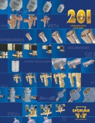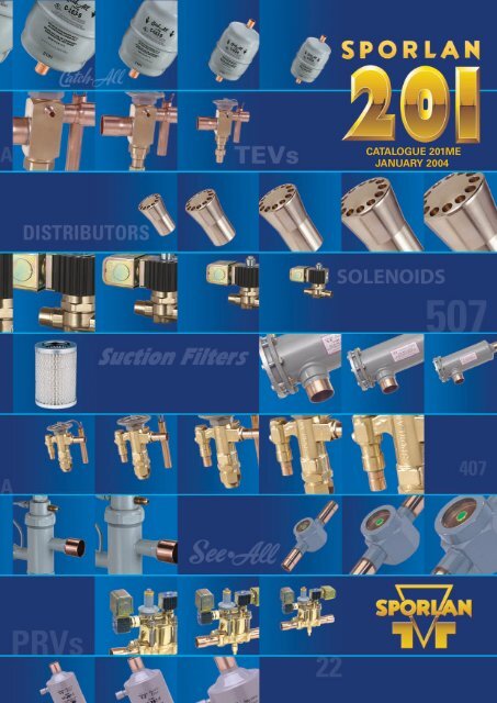
CATALOGUE 201ME JANUARY 2004
CATALOGUE 201ME JANUARY 2004
CATALOGUE 201ME JANUARY 2004

Create successful ePaper yourself
Turn your PDF publications into a flip-book with our unique Google optimized e-Paper software.
<strong>CATALOGUE</strong> <strong>201ME</strong><br />
<strong>JANUARY</strong> <strong>2004</strong>
Page 2 — <strong>CATALOGUE</strong> <strong>201ME</strong><br />
CONDENSED CATALOG <strong>201ME</strong> <strong>JANUARY</strong> <strong>2004</strong><br />
This catalogue is a condensed version of the complete Sporlan Catalogue. By including a minimum of<br />
engineering information we are able to provide a small, handy-sized reference of pertinent data and<br />
specifications on Sporlan products. If you need additional engineering information, or would like a copy of<br />
the complete Sporlan Catalogue, please contact your Sporlan Wholesaler or e-mail europecold@parker.com.<br />
CONTENTS<br />
Page<br />
*FOR COMPLETE PRODUCT<br />
INFORMATION SEE<br />
BULLETIN NUMBER<br />
ACID TEST KITS. . . . . . . . . . . . . . . . . . . . . . . . . . . . . . . . . . . . . 37 40-10<br />
Catch-All ® FILTER-DRIERS<br />
LIQUID & SUCTION LINE . . . . . . . . . . . . . . . . . . . . . . . . . 29 40-10<br />
CRANKCASE PRESSURE REGULATING VALVES . . . . . . . . . 40 90-10<br />
DEFROST DIFFERENTIAL PRESSURE REGULATING<br />
VALVES . . . . . . . . . . . . . . . . . . . . . . . . . . . . . . . . . . . . . . . 45 90-50<br />
DISCHARGE BYPASS VALVES . . . . . . . . . . . . . . . . . . . . . . . . 39 90-40<br />
ELECTRONIC TEMPERATURE CONTROL SYSTEMS . . . . . . 50 100-9, 100-20,<br />
100-20-1,100-40,<br />
100-50-1 & 100-60<br />
EVAPORATOR PRESSURE REGULATING VALVES . . . . . . . . 47<br />
90-20, 90-20-1 &<br />
90-20-2<br />
HEAD PRESSURE CONTROL VALVES . . . . . . . . . . . . . . . . . . 42 90-30<br />
HOT GAS DEFROST VALVES . . . . . . . . . . . . . . . . . . . . . . . . . . 28 30-20<br />
INDUSTRIAL SOLENOID VALVES . . . . . . . . . . . . . . . . . . . . . . 25 30-10<br />
LEVEL MASTER LIQUID LEVEL CONTROL . . . . . . . . . . . . . . 19 60-15<br />
“OF” SERIES OIL FILTER . . . . . . . . . . . . . . . . . . . . . . . . . . . . . 54 110-10<br />
OIL LEVEL CONTROL SYSTEM. . . . . . . . . . . . . . . . . . . . . . . . 52 110-10<br />
REFRIGERANT DISTRIBUTORS . . . . . . . . . . . . . . . . . . . . . . . 20 20-10<br />
REVERSIBLE HEAT PUMP FILTER-DRIER . . . . . . . . . . . . . . . 35 40-10<br />
See•All ® MOISTURE & LIQUID INDICATORS . . . . . . . . . . . . . 38 70-10<br />
SOLENOID VALVES . . . . . . . . . . . . . . . . . . . . . . . . . . . . . . . . . 21 30-10<br />
STRAINERS. . . . . . . . . . . . . . . . . . . . . . . . . . . . . . . . . . . . . . . . 35 80-20<br />
SUCTION FILTERS . . . . . . . . . . . . . . . . . . . . . . . . . . . . . . . . . . 36 80-10<br />
THERMOSTATIC EXPANSION VALVES. . . . . . . . . . . . . . . . . . . 3 10-9, 10-10,<br />
. . . . . . . . . . . . . . . . . . . . . . . . . . . . . . . . . . . . . . . . . . . . . . . . . . . . 10-10-5 & 10-10-6<br />
THREE WAY HEAT RECLAIM VALVES. . . . . . . . . . . . . . . . . . . 26 30-20<br />
*To request individual Sporlan Product Bulletins, please contact your Sporlan Wholesaler or email europecold@parker.com.<br />
Catalogue <strong>201ME</strong> is based on Catalog 201.<br />
Copyright 2003 by Sporlan Division - Parker Hannifin, Washington, Missouri<br />
FOR USE ON REFRIGERATION and/or AIR CONDITIONING SYSTEMS ONLY
<strong>CATALOGUE</strong> <strong>201ME</strong> — Page 3<br />
THERMOSTATIC EXPANSION VALVES<br />
10<br />
OUTSTANDING FEATURES & BENEFITS OF<br />
SPORLAN THERMOSTATIC EXPANSION VALVES<br />
• SELECTIVE THERMOSTATIC CHARGES Designed to provide<br />
optimum performance for all applications — air conditioning and<br />
heat pump, medium and low temperature refrigeration.<br />
• THERMOSTATIC ELEMENT DESIGN Long lasting and field proven<br />
stainless steel diaphragm and welded element construction.<br />
• DIAPHRAGM DESIGN Large flat diaphragm permits precise<br />
valve control.<br />
• REPLACEABLE THERMOSTATIC ELEMENTS Field replaceable<br />
elements on all standard valves.<br />
• BALANCED PORT DESIGN Provides perfect pin and port alignment,<br />
and prevents changes in pressure drop across the valve from<br />
influencing valve operation. Provides excellent control on<br />
applications with widely varying operating conditions.<br />
• PIN CARRIER DESIGN (CONVENTIONAL VALVES) Provides precise<br />
pin and port alignment, and tighter seating.<br />
• ACCESSIBLE INTERNAL PARTS Durable, leakproof body joint<br />
construction allows the valve to be disassembled, and the internal<br />
parts cleaned and inspected.<br />
• MATERIALS OF CONSTRUCTION Pin and port materials offer<br />
maximum protection against corrosion and erosion.<br />
• SILVER SOLDERED CONNECTIONS For leakproof, high strength<br />
connection-to-body joints.<br />
• ADJUSTABLE SUPERHEAT DESIGN All standard valves are externally<br />
adjustable except the Type NI, which is internally adjustable through<br />
its outlet connection.<br />
VALVE NOMENCLATURE / ORDERING INSTRUCTIONS — Combine the letters and numbers in the following manner to obtain<br />
the complete valve designation. Also include all connection sizes and the capillary tube length.<br />
EXAMPLE<br />
1/2" ODF<br />
S V E - 5 - C Solder<br />
Body<br />
Type<br />
S porlan<br />
Code – REFRIGERANT<br />
Element<br />
Label Color Code<br />
F - 12 - Yellow<br />
E - 13 - Blue<br />
G - 23 - Blue<br />
M - 124 - Blue<br />
J - 134a - Blue<br />
X - 401A - Pink<br />
L - 402A - Arena<br />
S - 404A - Sand<br />
V - 22, 407A - Green<br />
N - 407C - Lt. Brown<br />
R - 408A- Purple<br />
F - 409A - Yellow<br />
Z - 410A - Pink<br />
R- 502 - Purple<br />
W- 503 - Blue<br />
P- 507 - Teal<br />
W- 508B - Blue<br />
A- 717 - White<br />
"E" specifies<br />
external<br />
equaliser.<br />
Omission of<br />
letter "E"<br />
indicates<br />
valve with<br />
internal<br />
equaliser.<br />
eg.<br />
SV-5-C<br />
Nominal<br />
Capacity<br />
in<br />
tons<br />
Thermostatic<br />
Charge<br />
Inlet<br />
Connection<br />
Size<br />
and<br />
Style<br />
X<br />
7/8" ODF<br />
Solder<br />
Outlet<br />
Connection<br />
Size<br />
and<br />
Style<br />
X<br />
1/4" ODF<br />
Solder<br />
Equaliser<br />
Connection<br />
Size<br />
and<br />
Style<br />
X<br />
5'<br />
Capillary<br />
Tubing<br />
Length<br />
(inches<br />
or<br />
feet)<br />
SPORLAN SELECTIVE CHARGES ENGINEERED for PEAK PERFORMANCE for EACH SPECIFIC APPLICATION<br />
RECOMMENDED THERMOSTATIC CHARGES*<br />
APPLICATION<br />
AIR CONDITIONING<br />
COMMERCIAL REFRIGERATION<br />
10° C to<br />
– 25°<br />
C<br />
LOW TEMPERATURE<br />
REFRIGERATION<br />
– 20° C to<br />
– 40°<br />
C<br />
EXTREME LOW TEMP.<br />
REFRIGERATION<br />
– 40° C to<br />
– 75°<br />
C<br />
REFRIGERANT<br />
ACTUAL<br />
THERMOSTATIC<br />
CHARGES<br />
12<br />
22<br />
134a<br />
401A<br />
402A<br />
404A<br />
407C<br />
502<br />
507<br />
717<br />
409A<br />
407A<br />
408A<br />
F CP60 – JCP60<br />
X CP60<br />
– – – – – – FCP60<br />
– V CP100<br />
– – – – N CP100<br />
– – – VCP100<br />
– V GA<br />
– – – – N GA<br />
– – – VGA<br />
– – – – – S CP115<br />
– R CP115<br />
– – SCP115<br />
F C – JC<br />
X C – – – – – – FC<br />
– V C – – – – N C – – – VC<br />
– – – – – S C – R C – – SC<br />
– – – – L C – – – P C – PC<br />
– – – – – – – – – AC,<br />
AL<br />
AC, AL<br />
F Z – – – – – – – – – FZ<br />
F ZP – – – – – – – – – FZP<br />
– V Z – – – – – – – – VZ<br />
– V ZP40<br />
– – – – – – – – VZP40<br />
– – – – LZ<br />
– – – – LZP<br />
S Z – RZ<br />
S ZP<br />
– RZP<br />
– – – – – – – – – AZ,<br />
AL<br />
P Z – SZ<br />
P ZP<br />
– SZP<br />
AZ, AL<br />
– V X – – – – – – – – VX<br />
– – – – LX<br />
S X – RX<br />
P X – SX<br />
* APPLICATION FACTORS:<br />
1. The Type ZP charges have essentially the same characteristics as the Type Z charge with one exception: ZP charges produce a pressure limit Maximum Operating Pressure (MOP).<br />
ZP charges are not intended as replacements for Z charges. Each should be selected for its own unique purpose.<br />
2. All air conditioning and heat pump charges are intended for use with externally equalised valves.<br />
3. Type L Liquid charges are also available for most commonly used refrigerants in most element sizes.<br />
4. If in doubt as to which charge to use, contact your Sporlan Wholesaler or e-mail europecold@parker.com with complete system data.<br />
5. The Type X charges are not to be used with “EBS” and “O” valves.
Page 4 — <strong>CATALOGUE</strong> <strong>201ME</strong><br />
THERMOSTATIC EXPANSION VALVES<br />
12, 134a, 401A, 409A<br />
Capacities for Refrigerants - kW<br />
AIR CONDITIONING, HEAT PUMP and COMMERCIAL REFRIGERATION APPLICATIONS<br />
VALVE TYPES<br />
NOMINAL<br />
CAPACITY<br />
tons<br />
REFRIGERANT<br />
12<br />
134a<br />
401A<br />
409A<br />
RECOMMENDED THERMOSTATIC CHARGES<br />
FC,<br />
FCP60<br />
JC,<br />
JCP60<br />
XC,<br />
XCP60<br />
FC, FCP60<br />
EVAPORATOR TEMPERATURE<br />
k W 5 ° 0 ° - 10°<br />
5 ° 0 ° - 10°<br />
5 ° 0 ° - 10°<br />
5 ° 0 ° -10°<br />
NI-F-EF-G-EG<br />
1/<br />
8 0.44<br />
0.43<br />
0.49<br />
0.44<br />
0.51<br />
0.59<br />
0.52<br />
0.55<br />
0.63<br />
0.57<br />
0.51<br />
0.59<br />
0.53<br />
F-EF-G-EG<br />
1/<br />
6 0.59<br />
0.71<br />
0.85<br />
0.82<br />
0.85<br />
1.02<br />
0.97<br />
0.91<br />
1.10<br />
1.05<br />
0.85<br />
1.02<br />
0.99<br />
NI-F-EF-G-EG<br />
1/<br />
4 0.88<br />
0.89<br />
1.07<br />
1.02<br />
1.06<br />
1.27<br />
1.21<br />
1.14<br />
1.37<br />
1.33<br />
1.07<br />
1.28<br />
1.23<br />
NI-F-EF-G-EG<br />
1/<br />
2 1.76<br />
1.71<br />
1.96<br />
1.74<br />
2.04<br />
2.34<br />
2.08<br />
2.20<br />
2.53<br />
2.27<br />
2.06<br />
2.36<br />
2.11<br />
NI-F-EF-G-EG<br />
1 3.52<br />
3.42<br />
3.93<br />
3.50<br />
4.09<br />
4.68<br />
4.16<br />
4.40<br />
5.06<br />
4.53<br />
4.12<br />
4.73<br />
4.22<br />
F-EF-G-EG<br />
1-1/<br />
2 5.28<br />
5.47<br />
6.28<br />
5.60<br />
6.54<br />
7.50<br />
6.65<br />
7.04<br />
8.09<br />
7.25<br />
6.58<br />
7.56<br />
6.76<br />
F&EF(Ext)-G&EG(Ext)-C(Int)-S<br />
2 7.03<br />
6.84<br />
7.84<br />
7.00<br />
8.17<br />
9.37<br />
8.32<br />
8.79<br />
10.<br />
1 9.06<br />
8.23<br />
9.45<br />
8.45<br />
C-S<br />
2-1/<br />
2 8.79<br />
8.55<br />
9.81<br />
8.74<br />
10.<br />
2 11.<br />
7 10.<br />
4 11.<br />
0 12.<br />
6 11.<br />
3 10.<br />
3 11.<br />
8 10. 6<br />
F&EF(Ext)-C-S<br />
3 10.<br />
6 10.<br />
3 11.<br />
8 10.<br />
4 12.<br />
3 14.<br />
1 12.<br />
5 13.<br />
2 15.<br />
1 13.<br />
6 12.<br />
3 14.<br />
2 12. 6<br />
C&S(Ext)<br />
5 17.<br />
6 17.<br />
2 18.<br />
4 14.<br />
2 20.<br />
6 21.<br />
9 16.<br />
9 22.<br />
2 23.<br />
7 18.<br />
4 20.<br />
7 22.<br />
1 17. 1<br />
S(Ext)<br />
6 21.<br />
1 20.<br />
7 22.<br />
0 17.<br />
0 24.<br />
7 26.<br />
3 20.<br />
3 26.<br />
6 28.<br />
4 22.<br />
0 24.<br />
9 26.<br />
6 20. 6<br />
S(Ext)<br />
10<br />
35.<br />
2 31.<br />
9 34.<br />
8 27.<br />
9 38.<br />
2 41.<br />
5 33.<br />
2 41.<br />
1 44.<br />
8 36.<br />
1 38.<br />
4 41.<br />
9 33. 7<br />
H 1-1/<br />
2 5.28<br />
5.47<br />
6.28<br />
5.60<br />
6.54<br />
7.50<br />
6.65<br />
7.04<br />
8.09<br />
7.25<br />
6.58<br />
7.56<br />
6.76<br />
H 3 10.<br />
6 10.<br />
3 11.<br />
8 10.<br />
3 12.<br />
3 14.<br />
1 12.<br />
2 13.<br />
2 15.<br />
1 13.<br />
3 12.<br />
3 14.<br />
2 12. 3<br />
H 4 14.<br />
1 13.<br />
7 15.<br />
7 13.<br />
7 16.<br />
3 18.<br />
7 16.<br />
3 17.<br />
6 20.<br />
3 17.<br />
7 16.<br />
5 18.<br />
9 16. 5<br />
H 5 17.<br />
6 17.<br />
1 19.<br />
6 17.<br />
0 20.<br />
4 23.<br />
4 20.<br />
4 22.<br />
0 25.<br />
3 22.<br />
1 20.<br />
6 23.<br />
6 20. 6<br />
H 8 28.<br />
1 25.<br />
6 29.<br />
5 25.<br />
6 30.<br />
7 35.<br />
1 30.<br />
5 33.<br />
0 37.<br />
9 33.<br />
2 30.<br />
9 35.<br />
4 30. 9<br />
H 12<br />
42.<br />
2 40.<br />
0 45.<br />
9 39.<br />
9 47.<br />
8 54.<br />
8 47.<br />
5 51.<br />
4 59.<br />
2 51.<br />
7 48.<br />
1 55.<br />
4 48. 3<br />
M 13<br />
45.<br />
7 44.<br />
4 51.<br />
0 44.<br />
0 53.<br />
1 60.<br />
9 52.<br />
3 57.<br />
2 65.<br />
7 56.<br />
9 53.<br />
5 61.<br />
4 53. 1<br />
M 15<br />
52.<br />
8 53.<br />
0 60.<br />
8 52.<br />
3 63.<br />
4 72.<br />
6 62.<br />
4 68.<br />
2 78.<br />
4 67.<br />
9 63.<br />
8 73.<br />
3 63. 3<br />
M 20<br />
70.<br />
3 68.<br />
4 78.<br />
4 67.<br />
6 81.<br />
7 93.<br />
7 80.<br />
4 87.<br />
9 101<br />
87.<br />
5 82.<br />
3 94.<br />
5 81. 6<br />
M 25<br />
88.<br />
0 85.<br />
5 98.<br />
1 84.<br />
5 102<br />
117<br />
101<br />
110<br />
126<br />
110<br />
103<br />
118<br />
102<br />
BF-EBF-SBF-BQ-EBQ-SBQ<br />
° C<br />
BALANCED PORT THERMOSTATIC EXPANSION VALVES<br />
AAA<br />
0.70<br />
0.71<br />
0.85<br />
0.82<br />
0.85<br />
1.02<br />
0.97<br />
0.91<br />
1.10<br />
1.05<br />
0.85<br />
1.02<br />
0.99<br />
BF-EBF-SBF-BQ-EBQ-SBQ<br />
AA<br />
1.17<br />
1.54<br />
1.77<br />
1.58<br />
1.84<br />
2.11<br />
1.87<br />
1.98<br />
2.28<br />
2.04<br />
1.85<br />
2.13<br />
1.90<br />
BF-EBF-SBF-BQ-EBQ-SBQ<br />
A 3.52<br />
3.42<br />
3.93<br />
3.50<br />
4.09<br />
4.68<br />
4.16<br />
4.40<br />
5.06<br />
4.53<br />
4.12<br />
4.73<br />
4.22<br />
BF-EBF-SBF-BQ-EBQ-SBQ<br />
B 6.15<br />
5.81<br />
6.67<br />
5.94<br />
6.95<br />
7.96<br />
7.07<br />
7.48<br />
8.60<br />
7.70<br />
7.00<br />
8.03<br />
7.18<br />
BF-EBF-SBF-BQ-EBQ-SBQ<br />
C 10.<br />
6 10.<br />
3 11.<br />
8 10.<br />
4 12.<br />
3 14.<br />
1 12.<br />
5 13.<br />
2 15.<br />
1 13.<br />
6 12.<br />
3 14.<br />
2 12. 6<br />
EBS<br />
5 17.<br />
6 17.<br />
4 19.<br />
3 16.<br />
1 20.<br />
8 23.<br />
1 19.<br />
1 22.<br />
4 25.<br />
0 20.<br />
8 21.<br />
0 23.<br />
3 19. 4<br />
EBS<br />
7 24.<br />
6 24.<br />
0 26.<br />
6 22.<br />
1 28.<br />
7 31.<br />
9 26.<br />
3 30.<br />
9 34.<br />
4 28.<br />
7 28.<br />
9 32.<br />
2 26. 7<br />
EBS<br />
9 31.<br />
7 31.<br />
9 34.<br />
7 27.<br />
4 38.<br />
1 41.<br />
5 32.<br />
6 41.<br />
0 44.<br />
7 35.<br />
4 38.<br />
4 41.<br />
8 33. 0<br />
EBS<br />
12<br />
42.<br />
2 45.<br />
6 49.<br />
7 39.<br />
1 54.<br />
6 59.<br />
3 46.<br />
5 58.<br />
7 64.<br />
1 50.<br />
6 55.<br />
0 60.<br />
0 47. 1<br />
O 9 31.<br />
7 30.<br />
8 35.<br />
3 30.<br />
9 36.<br />
8 42.<br />
2 36.<br />
9 39.<br />
6 45.<br />
5 40.<br />
1 37.<br />
0 42.<br />
5 37. 4<br />
O 12<br />
42.<br />
2 40.<br />
0 45.<br />
9 40.<br />
2 47.<br />
8 54.<br />
8 47.<br />
8 51.<br />
4 59.<br />
2 52.<br />
1 48.<br />
1 55.<br />
4 48. 6<br />
O 16<br />
56.<br />
3 53.<br />
0 60.<br />
8 53.<br />
3 63.<br />
4 72.<br />
6 63.<br />
4 68.<br />
2 78.<br />
4 69.<br />
0 63.<br />
8 73.<br />
3 64. 3<br />
O 23<br />
80.<br />
9 78.<br />
3 93.<br />
3 84.<br />
9 93.<br />
6 112<br />
101<br />
101<br />
120<br />
110<br />
94.<br />
3 113<br />
103<br />
O 32<br />
113<br />
109<br />
130<br />
118<br />
130<br />
155<br />
141<br />
140<br />
167<br />
154<br />
131<br />
157<br />
143<br />
O 40<br />
141<br />
136<br />
162<br />
147<br />
163<br />
193<br />
176<br />
175<br />
209<br />
191<br />
164<br />
195<br />
179<br />
V 35<br />
123<br />
120<br />
137<br />
117<br />
143<br />
164<br />
140<br />
154<br />
177<br />
153<br />
144<br />
165<br />
142<br />
V 45<br />
158<br />
154<br />
177<br />
152<br />
184<br />
211<br />
180<br />
198<br />
228<br />
195<br />
185<br />
213<br />
183<br />
V 55<br />
193<br />
188<br />
216<br />
185<br />
225<br />
258<br />
219<br />
242<br />
278<br />
239<br />
226<br />
260<br />
223<br />
W 80<br />
281<br />
291<br />
333<br />
280<br />
347<br />
398<br />
334<br />
374<br />
430<br />
363<br />
350<br />
402<br />
338<br />
W 110<br />
387<br />
407<br />
- - 487<br />
- - 524<br />
- - 490<br />
- -<br />
V ALVE TYPE CARTRIDGE<br />
NO.<br />
REPLACEABLE CARTRIDGE THERMOSTATIC EXPANSION VALVES<br />
Q-EQ-SQ<br />
0 1/<br />
6 0.59<br />
0.68<br />
0.78<br />
0.70<br />
0.82<br />
0.94<br />
0.83<br />
0.88<br />
1.01<br />
0.91<br />
0.82<br />
0.95<br />
0.84<br />
Q-EQ-SQ<br />
1 1/<br />
4 0.88<br />
1.54<br />
1.77<br />
1.58<br />
1.84<br />
2.11<br />
1.87<br />
1.98<br />
2.28<br />
2.04<br />
1.85<br />
2.13<br />
1.90<br />
Q-EQ-SQ<br />
2 1/<br />
2 1.76<br />
2.22<br />
2.55<br />
2.28<br />
2.66<br />
3.04<br />
2.71<br />
2.86<br />
3.29<br />
2.95<br />
2.67<br />
3.07<br />
2.75<br />
Q-EQ-SQ<br />
3 1 3.52<br />
3.42<br />
3.93<br />
3.50<br />
4.09<br />
4.68<br />
4.16<br />
4.40<br />
5.06<br />
4.53<br />
4.12<br />
4.73<br />
4.22<br />
Q-EQ-SQ<br />
4 1-1/<br />
2 5.28<br />
4.79<br />
5.49<br />
4.90<br />
5.72<br />
6.56<br />
5.83<br />
6.16<br />
7.08<br />
6.34<br />
5.76<br />
6.62<br />
5.91<br />
Q-EQ-SQ<br />
5 2 7.03<br />
6.84<br />
7.84<br />
7.00<br />
8.17<br />
9.37<br />
8.32<br />
8.79<br />
10.<br />
1 9.06<br />
8.23<br />
9.45<br />
8.45<br />
Q-EQ-SQ<br />
6 2-1/<br />
2 8.79<br />
9.23<br />
10.<br />
6 9.44<br />
11.<br />
0 12.<br />
6 11.<br />
3 11.<br />
9 13.<br />
7 12.<br />
2 11.<br />
1 12.<br />
7 11. 4<br />
EVAPORATOR<br />
TEMPERATURE<br />
°C<br />
PRESSURE DROP ACROSS TEV bar<br />
2 4 6 8 10<br />
12<br />
14<br />
16<br />
CORRECTION FACTOR, CF PRESSURE DROP<br />
5°<br />
0.71<br />
1.00<br />
1.22<br />
1.41<br />
1.58<br />
1.73<br />
1.87<br />
2.00<br />
0°<br />
& -10° 0.58<br />
0.82<br />
1.00<br />
1.15<br />
1.29<br />
1.41<br />
1.53<br />
1.63<br />
TEV CAPACITY = TEV RATING X CF LIQUID<br />
TEMPERATURE X CF PRESSURE DROP<br />
Example: Actual capacity of a nominal 5 ton,<br />
R-134a Type S valve at 0°C evaporator, 6 bar<br />
pressure drop across the TEV, and 30°C liquid<br />
temperature entering the TEV, is: 21.9 kW(from<br />
rating chart) x 1.13 (CF liquid temperature) x<br />
1.00 (CF pressure drop) = 24.7 kW.<br />
LIQUID TEMPERATURE ENTERING TEV<br />
° C<br />
- 10° 0 ° 10°<br />
20°<br />
30°<br />
40°<br />
50°<br />
60°<br />
REFRIGERANT<br />
CORRECTION FACTOR,<br />
CF LIQUID TEMPERATURE<br />
12<br />
1.56<br />
1.45<br />
1.34<br />
1.23<br />
1.11<br />
1.00<br />
0.88<br />
0.77<br />
134a<br />
1.65<br />
1.53<br />
1.40<br />
1.27<br />
1.13<br />
1.00<br />
0.86<br />
0.72<br />
401A<br />
1.56<br />
1.46<br />
1.34<br />
1.23<br />
1.12<br />
1.00<br />
0.88<br />
0.75<br />
409A<br />
1.52<br />
1.42<br />
1.32<br />
1.21<br />
1.11<br />
1.00<br />
0.89<br />
0.78
<strong>CATALOGUE</strong> <strong>201ME</strong> — Page 5<br />
THERMOSTATIC EXPANSION VALVES<br />
22, 407A, 407C<br />
Capacities for Refrigerants - kW<br />
AIR CONDITIONING, HEAT PUMP and COMMERCIAL REFRIGERATION APPLICATIONS<br />
VALVE TYPES<br />
NOMINAL<br />
CAPACITY<br />
tons<br />
k W 5 ° °<br />
F-EF-G-EG<br />
1/<br />
5 0.70<br />
0.64<br />
.73<br />
NI<br />
1/<br />
4 0.88<br />
0.80<br />
.91<br />
F-EF-G-EG<br />
1/<br />
3 1.17<br />
1.12<br />
.28<br />
NI-F-EF-G-EG<br />
1/<br />
2 1.76<br />
1.45<br />
.65<br />
G-EG<br />
3/<br />
4 2.64<br />
2.41<br />
.75<br />
NI-F-EF-G-EG<br />
1 3.52<br />
3.21<br />
.67<br />
F-EF-G-EG<br />
1-1/<br />
2 5.28<br />
5.14<br />
.87<br />
F&EF(Ext)-G&EG(Ext)-S<br />
2 7.03<br />
6.43<br />
.34<br />
F&EF(Int)-G&EG(Int)<br />
2-1/<br />
2 8.79<br />
8.03<br />
.17<br />
F&EF(Ext)-G&EG(Ext)-C(Int)-S<br />
3 10.<br />
6 10.<br />
3 1. 7<br />
C-S<br />
4 14.<br />
1 14.<br />
5 6. 5<br />
F&EF(Ext)-C-S<br />
5 17.<br />
6 16.<br />
7 9. 1<br />
C&S(Ext)<br />
8 28.<br />
1 25.<br />
7 9. 4<br />
S(Ext)<br />
10<br />
35.<br />
2 32.<br />
1 6. 7<br />
S(Ext)<br />
15<br />
52.<br />
8 49.<br />
8 6. 9<br />
H 2-1/<br />
2 8.79<br />
8.04<br />
.10<br />
H 5-1/<br />
2 19.<br />
3 18.<br />
0 0. 4<br />
H 7 24.<br />
6 22.<br />
5 5. 5<br />
H 11<br />
38.<br />
7 33.<br />
8 8. 2<br />
H 16<br />
56.<br />
3 48.<br />
9 5. 3<br />
H 20<br />
70.<br />
3 71.<br />
4 0. 8<br />
M 21<br />
73.<br />
9 69.<br />
1 8. 9<br />
M 26<br />
91.<br />
4 85.<br />
2 7. 2<br />
M 34<br />
120<br />
109<br />
25<br />
M 42<br />
148<br />
135<br />
54<br />
REFRIGERANT<br />
22<br />
407A<br />
407C<br />
VC,<br />
VCP100, VGA VZ,<br />
VZP40<br />
0 °<br />
0 9<br />
0 9<br />
1 2<br />
1 6<br />
2 0<br />
3 7<br />
5 6<br />
7 5<br />
9 8<br />
1 1<br />
1 6<br />
1 1<br />
2 2<br />
3 0<br />
5 7<br />
9 6<br />
2 2<br />
2 0<br />
3 9<br />
5 0<br />
8 0<br />
7 7<br />
9 6<br />
1 1<br />
1 0<br />
RECOMMENDED THERMOSTATIC CHARGES<br />
VC,<br />
VCP100, VGA<br />
VZ,<br />
VZP40<br />
NC, NCP100, NGA<br />
EVAPORATOR TEMPERATURE ° C<br />
- 10 - 20°<br />
- 30°<br />
- 40°<br />
5 ° 0 ° - 10°<br />
- 20°<br />
- 30°<br />
- 40°<br />
5 ° 0 ° -10°<br />
0.6<br />
0.65<br />
0.49<br />
0.39<br />
0.60<br />
0.67<br />
0.63<br />
0.58<br />
0.43<br />
0.33<br />
0.59<br />
0.66<br />
0.80<br />
0.8<br />
0.93<br />
0.78<br />
0.61<br />
0.74<br />
0.84<br />
0.80<br />
0.83<br />
0.67<br />
0.51<br />
0.73<br />
0.82<br />
0.78<br />
1.2<br />
1.10<br />
0.79<br />
0.62<br />
1.04<br />
1.18<br />
1.10<br />
0.98<br />
0.68<br />
0.52<br />
1.02<br />
1.16<br />
1.08<br />
1.5<br />
1.42<br />
1.02<br />
0.80<br />
1.34<br />
1.52<br />
1.41<br />
1.26<br />
0.89<br />
0.68<br />
1.32<br />
1.52<br />
1.39<br />
2.6<br />
2.51<br />
1.99<br />
1.55<br />
2.24<br />
2.53<br />
2.35<br />
2.21<br />
1.72<br />
1.32<br />
2.19<br />
2.49<br />
2.32<br />
3.4<br />
3.28<br />
2.52<br />
1.96<br />
2.98<br />
3.38<br />
3.13<br />
2.89<br />
2.18<br />
1.67<br />
2.93<br />
3.32<br />
3.09<br />
5.5<br />
5.03<br />
3.57<br />
2.79<br />
4.77<br />
5.39<br />
5.01<br />
4.44<br />
3.09<br />
2.36<br />
4.68<br />
5.31<br />
4.95<br />
6.9<br />
6.88<br />
5.74<br />
4.47<br />
5.96<br />
6.74<br />
6.26<br />
6.08<br />
4.96<br />
3.79<br />
5.85<br />
6.63<br />
6.18<br />
8.6<br />
8.26<br />
6.44<br />
5.02<br />
7.46<br />
8.43<br />
7.83<br />
7.30<br />
5.57<br />
4.26<br />
7.31<br />
8.29<br />
7.73<br />
11.<br />
9.91<br />
6.82<br />
5.32<br />
9.54<br />
10.<br />
8 9.99<br />
8.75<br />
5.90<br />
4.50<br />
9.36<br />
10.<br />
6 9.89<br />
15.<br />
14.<br />
1 10.<br />
0 7.83<br />
13.<br />
4 15.<br />
1 14.<br />
1 12.<br />
5 8.69<br />
6.63<br />
13.<br />
2 14.<br />
9 13. 9<br />
18.<br />
16.<br />
4 11.<br />
8 9.22<br />
15.<br />
5 17.<br />
6 16.<br />
3 14.<br />
5 10.<br />
2 7.81<br />
15.<br />
2 17.<br />
2 16. 1<br />
27.<br />
23.<br />
5 15.<br />
9 12.<br />
3 23.<br />
8 27.<br />
0 24.<br />
5 20.<br />
7 13.<br />
8 10.<br />
4 23.<br />
4 26.<br />
5 24. 2<br />
34.<br />
29.<br />
3 19.<br />
9 15.<br />
3 29.<br />
8 33.<br />
8 30.<br />
7 25.<br />
9 17.<br />
2 13.<br />
0 29.<br />
3 33.<br />
2 30. 2<br />
52.<br />
46.<br />
2 31.<br />
2 24.<br />
9 46.<br />
2 52.<br />
3 47.<br />
4 40.<br />
8 27.<br />
0 21.<br />
0 45.<br />
3 51.<br />
4 46. 9<br />
8.5<br />
8.12<br />
5.10<br />
4.28<br />
7.46<br />
8.36<br />
7.71<br />
7.20<br />
4.41<br />
3.63<br />
7.32<br />
8.22<br />
7.62<br />
19.<br />
18.<br />
0 11.<br />
1 9.35<br />
16.<br />
7 18.<br />
7 17.<br />
3 15.<br />
9 9.64<br />
7.92<br />
16.<br />
4 18.<br />
4 17. 1<br />
24.<br />
21.<br />
7 12.<br />
5 10.<br />
5 20.<br />
9 23.<br />
4 21.<br />
6 19.<br />
2 10.<br />
8 8.87<br />
20.<br />
5 23.<br />
0 21. 3<br />
35.<br />
31.<br />
6 17.<br />
0 14.<br />
3 31.<br />
3 35.<br />
1 32.<br />
4 27.<br />
9 14.<br />
7 12.<br />
1 30.<br />
7 34.<br />
5 32. 0<br />
52.<br />
45.<br />
6 24.<br />
3 20.<br />
4 45.<br />
3 50.<br />
8 46.<br />
9 40.<br />
3 21.<br />
0 17.<br />
3 44.<br />
5 50.<br />
0 46. 3<br />
76.<br />
68.<br />
9 39.<br />
6 33.<br />
2 66.<br />
2 74.<br />
2 68.<br />
5 60.<br />
9 34.<br />
2 28.<br />
1 65.<br />
0 73.<br />
0 67. 6<br />
76.<br />
74.<br />
8 53.<br />
6 45.<br />
2 64.<br />
1 72.<br />
5 69.<br />
2 66.<br />
1 46.<br />
4 38.<br />
3 62.<br />
9 71.<br />
3 68. 3<br />
94.<br />
96.<br />
8 75.<br />
8 63.<br />
9 80.<br />
0 89.<br />
4 85.<br />
3 85.<br />
5 65.<br />
6 54.<br />
1 77.<br />
5 87.<br />
9 84. 2<br />
12<br />
120<br />
89.<br />
2 75.<br />
2 101<br />
115<br />
110<br />
106<br />
77.<br />
2 63.<br />
7 99.<br />
5 113<br />
108<br />
15<br />
151<br />
107<br />
86.<br />
2 125<br />
142<br />
135<br />
134<br />
92.<br />
8 73.<br />
0 123<br />
139<br />
133<br />
BALANCED PORT THERMOSTATIC EXPANSION VALVES<br />
1.2<br />
1.10<br />
0.79<br />
0.61<br />
1.04<br />
1.18<br />
1.10<br />
0.98<br />
0.68<br />
0.52<br />
1.02<br />
1.16<br />
1.08<br />
2.6<br />
2.51<br />
1.99<br />
1.55<br />
2.24<br />
2.53<br />
2.35<br />
2.21<br />
1.72<br />
1.32<br />
2.19<br />
2.49<br />
2.32<br />
5.5<br />
5.03<br />
3.57<br />
2.79<br />
4.77<br />
5.39<br />
5.01<br />
4.44<br />
3.09<br />
2.36<br />
4.68<br />
5.31<br />
4.95<br />
9.7<br />
8.96<br />
6.59<br />
5.14<br />
8.35<br />
9.44<br />
8.76<br />
7.92<br />
5.70<br />
4.35<br />
8.19<br />
9.29<br />
8.66<br />
18.<br />
16.<br />
4 11.<br />
8 9.22<br />
15.<br />
5 17.<br />
6 16.<br />
3 14.<br />
5 10.<br />
2 7.81<br />
15.<br />
2 17.<br />
2 16. 1<br />
27.<br />
24.<br />
5 16.<br />
8 13.<br />
0 25.<br />
4 28.<br />
1 24.<br />
9 21.<br />
6 14.<br />
5 10.<br />
9 24.<br />
9 27.<br />
6 24. 6<br />
37.<br />
33.<br />
1 22.<br />
7 17.<br />
5 34.<br />
4 38.<br />
0 33.<br />
7 29.<br />
3 19.<br />
7 14.<br />
8 33.<br />
7 37.<br />
4 33. 3<br />
49.<br />
42.<br />
0 29.<br />
1 23.<br />
4 46.<br />
2 51.<br />
4 44.<br />
9 37.<br />
1 25.<br />
2 19.<br />
8 45.<br />
3 50.<br />
6 44. 3<br />
69.<br />
58.<br />
3 40.<br />
2 29.<br />
6 66.<br />
7 73.<br />
4 62.<br />
8 51.<br />
5 34.<br />
8 25.<br />
1 65.<br />
5 72.<br />
2 62. 0<br />
48.<br />
41.<br />
3 26.<br />
7 21.<br />
0 44.<br />
8 49.<br />
6 44.<br />
1 36.<br />
5 23.<br />
1 17.<br />
8 44.<br />
0 48.<br />
7 43. 6<br />
72.<br />
64.<br />
8 39.<br />
6 33.<br />
2 66.<br />
3 73.<br />
3 65.<br />
3 57.<br />
2 34.<br />
2 28.<br />
1 65.<br />
1 72.<br />
1 64. 5<br />
99.<br />
84.<br />
9 56.<br />
5 49.<br />
1 91.<br />
2 101<br />
89.<br />
6 75.<br />
0 48.<br />
9 41.<br />
6 89.<br />
4 99.<br />
1 88. 6<br />
13<br />
111<br />
86.<br />
1 74.<br />
6 120<br />
136<br />
119<br />
98.<br />
0 74.<br />
5 63.<br />
2 118<br />
133<br />
118<br />
18<br />
150<br />
98.<br />
2 83.<br />
0 164<br />
184<br />
163<br />
133<br />
85.<br />
0 70.<br />
4 161<br />
182<br />
161<br />
24<br />
198<br />
111<br />
90.<br />
4 217<br />
245<br />
216<br />
175<br />
96.<br />
4 76.<br />
6 214<br />
241<br />
214<br />
18<br />
190<br />
121<br />
101<br />
155<br />
175<br />
166<br />
168<br />
105<br />
85.<br />
4 152<br />
172<br />
164<br />
25<br />
265<br />
167<br />
138<br />
217<br />
246<br />
233<br />
234<br />
144<br />
117<br />
214<br />
241<br />
230<br />
35<br />
355<br />
215<br />
178<br />
298<br />
336<br />
318<br />
313<br />
186<br />
151<br />
293<br />
330<br />
315<br />
50<br />
508<br />
307<br />
255<br />
426<br />
480<br />
455<br />
448<br />
266<br />
216<br />
419<br />
472<br />
450<br />
56<br />
- - - - - 553<br />
- -<br />
BF-EBF-SBF-BQ-EBQ-S<br />
Q B AAA<br />
1.17<br />
1.12<br />
1.28<br />
2<br />
BF-EBF-SBF-BQ-EBQ-S<br />
Q B AA<br />
2.34<br />
2.41<br />
2.75<br />
0<br />
BF-EBF-SBF-BQ-EBQ-S Q B A 5.28<br />
5.14<br />
5.87<br />
6<br />
BF-EBF-SBF-BQ-EBQ-S Q B B 10.<br />
6 9.00<br />
10.<br />
3 2<br />
BF-EBF-SBF-BQ-EBQ-S Q B C 19.<br />
3 16.<br />
7 19.<br />
1 1<br />
EBS<br />
8 28.<br />
1 27.<br />
4 30.<br />
6 6<br />
EBS<br />
11<br />
38.<br />
7 37.<br />
1 41.<br />
4 4<br />
EBS<br />
15<br />
52.<br />
8 49.<br />
8 56.<br />
0 8<br />
EBS<br />
20<br />
70.<br />
3 72.<br />
0 79.<br />
9 7<br />
O 15<br />
52.<br />
8 48.<br />
3 53.<br />
9 9<br />
O 20<br />
70.<br />
3 71.<br />
5 79.<br />
8 4<br />
O 30<br />
106<br />
98.<br />
3 110<br />
5<br />
O 40<br />
141<br />
130<br />
147<br />
2<br />
O 55<br />
193<br />
177<br />
201<br />
1<br />
O 70<br />
246<br />
235<br />
267<br />
0<br />
V 52<br />
183<br />
167<br />
190<br />
4<br />
V 70<br />
246<br />
235<br />
267<br />
8<br />
V 100<br />
352<br />
322<br />
365<br />
3<br />
W 135<br />
475<br />
460<br />
523<br />
5<br />
W 180<br />
633<br />
607<br />
- - - - - 3<br />
V ALVE TYPE CARTRIDGE<br />
NO.<br />
REPLACEABLE<br />
CARTRIDGE THERMOSTATIC<br />
EXPANSION<br />
VALVES<br />
Q-EQ-SQ<br />
0 1/<br />
3 1.17<br />
1.12<br />
1.28<br />
1.22<br />
1.10<br />
0.79<br />
0.61<br />
1.04<br />
1.18<br />
1.10<br />
0.98<br />
0.68<br />
0.52<br />
1.02<br />
1.16<br />
1.08<br />
Q-EQ-SQ<br />
1 3/<br />
4 2.64<br />
2.41<br />
2.75<br />
2.60<br />
2.51<br />
1.99<br />
1.55<br />
2.24<br />
2.53<br />
2.35<br />
2.21<br />
1.72<br />
1.32<br />
2.19<br />
2.49<br />
2.32<br />
Q-EQ-SQ<br />
2 1 3.52<br />
3.21<br />
3.67<br />
3.47<br />
3.28<br />
2.52<br />
1.96<br />
2.98<br />
3.38<br />
3.13<br />
2.89<br />
2.18<br />
1.67<br />
2.93<br />
3.32<br />
3.09<br />
Q-EQ-SQ<br />
3 1-1/<br />
2 5.28<br />
4.82<br />
5.50<br />
5.21<br />
4.66<br />
3.22<br />
2.51<br />
4.47<br />
5.05<br />
4.70<br />
4.11<br />
2.79<br />
2.12<br />
4.39<br />
4.97<br />
4.64<br />
Q-EQ-SQ<br />
4 2-1/<br />
2 8.79<br />
8.03<br />
9.17<br />
8.68<br />
8.26<br />
6.44<br />
5.02<br />
7.46<br />
8.43<br />
7.83<br />
7.30<br />
5.57<br />
4.26<br />
7.31<br />
8.29<br />
7.73<br />
Q-EQ-SQ<br />
5 3-1/<br />
2 12.<br />
3 11.<br />
2 12.<br />
8 12.<br />
2 11.<br />
5 8.78<br />
6.85<br />
10.<br />
4 11.<br />
8 11.<br />
0 10.<br />
1 7.60<br />
5.80<br />
10.<br />
2 11.<br />
6 10. 8<br />
Q-EQ-SQ<br />
6 5 17.<br />
6 15.<br />
4 17.<br />
6 16.<br />
7 15.<br />
1 10.<br />
7 8.33<br />
14.<br />
3 16.<br />
2 15.<br />
0 13.<br />
3 9.24<br />
7.06<br />
14.<br />
0 15.<br />
9 14. 8<br />
-- VGA and NGA Thermostatic Charges Only --<br />
RCVE<br />
2 7.03<br />
7.39<br />
8.43<br />
8.03<br />
- - - - - - - - - - - -<br />
RCVE<br />
3 10.<br />
3 10.<br />
3 11.<br />
7 11.<br />
2 - - - - - - - - - - - -<br />
RCVE<br />
4 14.<br />
1 13.<br />
5 15.<br />
7 14.<br />
7 - - - - - - - - - - - -<br />
RCVE<br />
5 17.<br />
6 16.<br />
5 18.<br />
3 17.<br />
5 - - - - - - - - - - - -<br />
RCVE<br />
6 21.<br />
1 19.<br />
3 22.<br />
0 20.<br />
4 - - - - - - - - - - - -<br />
EVAPORATOR<br />
TEMPERATURE<br />
°C<br />
PRESSURE<br />
DROP ACROSS<br />
TEV bar<br />
2 4 6 8 10<br />
12<br />
14<br />
16<br />
CORRECTION FACTOR, CF PRESSURE DROP<br />
5°<br />
0.58<br />
0.82<br />
1.00<br />
1.15<br />
1.29<br />
1.41<br />
1.53<br />
1.63<br />
0°<br />
& –10° 0.50<br />
0.71<br />
0.87<br />
1.00<br />
1.12<br />
1.22<br />
1.32<br />
1.41<br />
– 20° & –30° 0.45<br />
0.63<br />
0.77<br />
0.89<br />
1.00<br />
1.10<br />
1.18<br />
1.26<br />
– 40° 0.41<br />
0.58<br />
0.71<br />
0.82<br />
0.91<br />
1.00<br />
1.08<br />
1.15<br />
TEV CAPACITY = TEV RATING X CF LIQUID<br />
TEMPERATURE X CF PRESSURE DROP —<br />
Example: Actual capacity of a nominal 10 ton<br />
R-22 Type S valve at -10°C evaporator, 8 bar<br />
pressure drop across the TEV, and 30°C liquid<br />
temperature entering the TEV = 34.0 (from rating<br />
chart) x 1.11 (CF liquid temperature) x 1.00<br />
(CF pressure drop) = 37.7 kW<br />
REFRIGERANT<br />
LIQUID TEMPERATURE ENTERING TEV<br />
° C<br />
- 20° - 10°<br />
0 ° 10°<br />
20°<br />
30°<br />
40°<br />
50°<br />
60°<br />
CORRECTION FACTOR,<br />
CF LIQUID TEMPERATURE<br />
22<br />
1.63<br />
1.53<br />
1.42<br />
1.32<br />
1.21<br />
1.11<br />
1.00<br />
0.89<br />
0.78<br />
407A<br />
1.85<br />
1.71<br />
1.57<br />
1.44<br />
1.30<br />
1.15<br />
1.00<br />
0.84<br />
0.66<br />
407C<br />
1.88<br />
1.74<br />
1.60<br />
1.46<br />
1.31<br />
1.16<br />
1.00<br />
0.84<br />
0.66
Page 6 — <strong>CATALOGUE</strong> <strong>201ME</strong><br />
THERMOSTATIC EXPANSION VALVES<br />
404A, 408A, 502<br />
Capacities for Refrigerants - kW<br />
AIR CONDITIONING, HEAT PUMP and COMMERCIAL REFRIGERATION APPLICATIONS<br />
VALVE TYPES<br />
NOMINAL<br />
CAPACITY<br />
tons<br />
SC,<br />
SCP115<br />
REFRIGERANT<br />
404A<br />
408A<br />
502<br />
RECOMMENDED THERMOSTATIC CHARGES<br />
SZ,<br />
SZP<br />
RC,<br />
RCP115<br />
EVAPORATOR TEMPERATURE<br />
RZ,<br />
RZP<br />
RC,<br />
RCP115<br />
° C<br />
RZ, RZP<br />
k W 5 ° 0 ° - 10°<br />
- 20°<br />
- 30°<br />
- 40°<br />
5 ° 0°<br />
- 10° - 20°<br />
- 30°<br />
- 40°<br />
5 ° 0 ° - 10°<br />
- 20°<br />
- 30°<br />
-40°<br />
NI-F-EF-G-EG<br />
1/<br />
8 0.44<br />
0.46<br />
0.52<br />
0.49<br />
0.52<br />
0.42<br />
0.37<br />
0.63<br />
0.71<br />
0.69<br />
0.74<br />
0.62<br />
0.55<br />
0.46<br />
0.52<br />
0.49<br />
0.52<br />
0.44<br />
0.38<br />
F-EF-G-EG<br />
1/<br />
6 0.59<br />
0.72<br />
0.81<br />
0.77<br />
0.82<br />
0.67<br />
0.58<br />
0.99<br />
1.12<br />
1.08<br />
1.16<br />
0.97<br />
0.86<br />
0.72<br />
0.81<br />
0.78<br />
0.83<br />
0.68<br />
0.59<br />
NI-F-EF-G-EG<br />
1/<br />
4 0.88<br />
0.92<br />
1.04<br />
0.98<br />
1.04<br />
0.85<br />
0.73<br />
1.26<br />
1.43<br />
1.38<br />
1.48<br />
1.24<br />
1.09<br />
0.91<br />
1.03<br />
0.99<br />
1.05<br />
0.87<br />
0.76<br />
NI-F-EF-G-EG<br />
1/<br />
2 1.76<br />
1.76<br />
1.98<br />
1.88<br />
1.98<br />
1.63<br />
1.40<br />
2.39<br />
2.72<br />
2.62<br />
2.81<br />
2.36<br />
2.08<br />
1.74<br />
1.97<br />
1.88<br />
2.00<br />
1.66<br />
1.45<br />
NI-F-EF-G-EG<br />
1 3.52<br />
3.21<br />
3.65<br />
3.51<br />
3.70<br />
3.03<br />
2.61<br />
4.38<br />
5.02<br />
4.89<br />
5.25<br />
4.39<br />
3.88<br />
3.18<br />
3.63<br />
3.51<br />
3.73<br />
3.09<br />
2.70<br />
F-EF-G-EG<br />
1-1/<br />
2 5.28<br />
4.83<br />
5.42<br />
4.98<br />
4.94<br />
4.05<br />
3.49<br />
6.58<br />
7.43<br />
6.95<br />
7.01<br />
5.87<br />
5.19<br />
4.77<br />
5.37<br />
4.98<br />
4.99<br />
4.13<br />
3.61<br />
F&EF(Ext)-G&EG(Ext)-C(Int)-S<br />
2 7.03<br />
6.43<br />
7.22<br />
6.63<br />
6.55<br />
5.40<br />
4.66<br />
8.77<br />
9.90<br />
9.24<br />
9.30<br />
7.83<br />
6.93<br />
6.36<br />
7.17<br />
6.62<br />
6.61<br />
5.51<br />
4.81<br />
F&EF(Ext)-C-S<br />
3 10.<br />
6 9.01<br />
10.<br />
1 9.22<br />
8.66<br />
6.75<br />
5.82<br />
12.<br />
3 13.<br />
9 12.<br />
8 12.<br />
3 9.79<br />
8.65<br />
8.91<br />
10.<br />
0 9.22<br />
8.73<br />
6.89<br />
6.01<br />
C-S<br />
4 14.<br />
1 12.<br />
9 14.<br />
4 13.<br />
2 12.<br />
3 9.46<br />
8.15<br />
17.<br />
6 19.<br />
8 18.<br />
3 17.<br />
4 13.<br />
7 12.<br />
2 12.<br />
7 14.<br />
3 13.<br />
2 12.<br />
4 9.64<br />
8.42<br />
C&S(Ext)<br />
6 21.<br />
1 17.<br />
8 18.<br />
8 15.<br />
7 15.<br />
2 12.<br />
3 9.90<br />
24.<br />
2 25.<br />
8 21.<br />
9 21.<br />
5 17.<br />
8 14.<br />
7 17.<br />
6 18.<br />
7 15.<br />
7 15.<br />
3 12.<br />
5 10. 2<br />
S(Ext)<br />
7 24.<br />
6 22.<br />
7 24.<br />
0 20.<br />
0 19.<br />
3 15.<br />
6 12.<br />
6 30.<br />
9 32.<br />
9 27.<br />
8 27.<br />
4 22.<br />
7 18.<br />
7 22.<br />
4 23.<br />
8 20.<br />
0 19.<br />
5 15.<br />
9 13. 0<br />
S(Ext)<br />
10<br />
35.<br />
2 32.<br />
5 34.<br />
7 29.<br />
9 30.<br />
3 26.<br />
2 23.<br />
5 44.<br />
3 47.<br />
5 41.<br />
7 43.<br />
0 38.<br />
0 34.<br />
9 32.<br />
2 34.<br />
4 29.<br />
9 30.<br />
6 26.<br />
7 24. 3<br />
H 1-1/<br />
2 5.28<br />
4.85<br />
5.22<br />
4.66<br />
4.94<br />
3.99<br />
3.31<br />
6.61<br />
7.16<br />
6.49<br />
7.01<br />
5.79<br />
4.91<br />
4.79<br />
5.18<br />
4.66<br />
4.99<br />
4.07<br />
3.41<br />
H 3 10.<br />
6 9.05<br />
9.75<br />
8.41<br />
8.24<br />
6.65<br />
5.51<br />
12.<br />
3 13.<br />
4 11.<br />
7 11.<br />
7 9.64<br />
8.18<br />
8.85<br />
9.67<br />
8.41<br />
8.31<br />
6.78<br />
5.69<br />
H 4 14.<br />
1 12.<br />
9 13.<br />
9 11.<br />
8 11.<br />
3 9.31<br />
7.71<br />
17.<br />
7 19.<br />
1 16.<br />
5 16.<br />
1 13.<br />
5 11.<br />
4 12.<br />
8 13.<br />
8 11.<br />
8 11.<br />
4 9.50<br />
7.96<br />
H 6-1/<br />
2 22.<br />
9 21.<br />
0 22.<br />
6 19.<br />
3 18.<br />
1 14.<br />
5 12.<br />
0 28.<br />
7 31.<br />
0 26.<br />
8 25.<br />
6 21.<br />
0 17.<br />
8 20.<br />
8 22.<br />
4 19.<br />
2 18.<br />
2 14.<br />
8 12. 4<br />
H 9 31.<br />
7 30.<br />
7 33.<br />
1 28.<br />
1 24.<br />
2 16.<br />
6 13.<br />
8 41.<br />
9 45.<br />
4 39.<br />
2 34.<br />
3 24.<br />
1 20.<br />
4 30.<br />
4 32.<br />
8 28.<br />
1 24.<br />
4 16.<br />
9 14. 2<br />
H 12<br />
42.<br />
2 42.<br />
0 45.<br />
3 38.<br />
5 35.<br />
0 26.<br />
6 22.<br />
0 57.<br />
2 62.<br />
1 53.<br />
7 49.<br />
6 38.<br />
6 32.<br />
8 41.<br />
6 44.<br />
9 38.<br />
5 35.<br />
3 27.<br />
1 22. 7<br />
M 15<br />
52.<br />
8 50.<br />
8 57.<br />
3 51.<br />
3 46.<br />
4 39.<br />
7 33.<br />
2 69.<br />
3 78.<br />
6 71.<br />
4 65.<br />
8 57.<br />
5 49.<br />
4 50.<br />
3 56.<br />
8 51.<br />
2 46.<br />
8 40.<br />
4 34. 3<br />
M 20<br />
70.<br />
3 66.<br />
2 74.<br />
7 66.<br />
2 58.<br />
2 49.<br />
7 41.<br />
7 90.<br />
6 103<br />
92.<br />
2 82.<br />
6 72.<br />
0 61.<br />
9 65.<br />
5 74.<br />
1 66.<br />
2 58.<br />
7 50.<br />
7 43. 0<br />
M 25<br />
87.<br />
9 82.<br />
6 93.<br />
2 82.<br />
6 70.<br />
9 58.<br />
3 48.<br />
9 112<br />
128<br />
115<br />
101<br />
84.<br />
5 72.<br />
6 81.<br />
7 92.<br />
4 82.<br />
6 71.<br />
5 59.<br />
5 50. 5<br />
M 30<br />
106<br />
99.<br />
7 112<br />
99.<br />
6 84.<br />
2 67.<br />
5 56.<br />
6 136<br />
154<br />
139<br />
119<br />
97.<br />
9 84.<br />
2 98.<br />
6 112<br />
99.<br />
6 86.<br />
0 68.<br />
8 58. 4<br />
BALANCED PORT THERMOSTATIC EXPANSION VALVES<br />
BF-EBF-SBF-BQ-EBQ-SBQ<br />
AAA<br />
0.70<br />
0.72<br />
0.82<br />
0.78<br />
0.82<br />
0.67<br />
0.58<br />
0.99<br />
1.12<br />
1.08<br />
1.16<br />
0.97<br />
0.86<br />
0.72<br />
0.81<br />
0.78<br />
0.82<br />
0.68<br />
0.60<br />
BF-EBF-SBF-BQ-EBQ-SBQ<br />
AA<br />
1.17<br />
1.45<br />
1.63<br />
1.55<br />
1.58<br />
1.24<br />
1.07<br />
1.98<br />
2.24<br />
2.15<br />
2.25<br />
1.80<br />
1.59<br />
1.43<br />
1.62<br />
1.55<br />
1.60<br />
1.26<br />
1.10<br />
BF-EBF-SBF-BQ-EBQ-SBQ<br />
A 3.52<br />
3.21<br />
3.65<br />
3.51<br />
3.70<br />
3.03<br />
2.61<br />
4.38<br />
5.02<br />
4.89<br />
5.25<br />
4.39<br />
3.88<br />
3.18<br />
3.63<br />
3.51<br />
3.73<br />
3.09<br />
2.70<br />
BF-EBF-SBF-BQ-EBQ-SBQ<br />
B 7.03<br />
5.95<br />
6.68<br />
6.09<br />
5.70<br />
4.41<br />
3.80<br />
8.13<br />
9.17<br />
8.49<br />
8.08<br />
6.39<br />
5.65<br />
5.89<br />
6.63<br />
6.09<br />
5.74<br />
4.50<br />
3.93<br />
BF-EBF-SBF-BQ-EBQ-SBQ<br />
C 10.<br />
6 9.01<br />
10.<br />
1 9.22<br />
8.66<br />
6.75<br />
5.82<br />
12.<br />
3 13.<br />
9 12.<br />
8 12.<br />
3 9.79<br />
8.65<br />
8.91<br />
10.<br />
0 9.22<br />
8.73<br />
6.89<br />
6.01<br />
EBS<br />
6 21.<br />
1 18.<br />
1 19.<br />
7 17.<br />
2 15.<br />
5 10.<br />
6 9.87<br />
24.<br />
7 27.<br />
1 24.<br />
0 21.<br />
9 15.<br />
4 14.<br />
7 17.<br />
9 19.<br />
6 17.<br />
2 15.<br />
6 10.<br />
8 10. 2<br />
EBS<br />
7-1/<br />
2 26.<br />
4 24.<br />
5 26.<br />
8 23.<br />
4 20.<br />
5 13.<br />
5 12.<br />
6 33.<br />
4 36.<br />
8 32.<br />
6 29.<br />
1 19.<br />
6 18.<br />
7 24.<br />
3 26.<br />
6 23.<br />
4 20.<br />
7 13.<br />
8 13. 0<br />
EBS<br />
10<br />
35.<br />
2 30.<br />
2 33.<br />
3 28.<br />
8 24.<br />
6 17.<br />
9 15.<br />
5 41.<br />
2 45.<br />
7 40.<br />
2 34.<br />
9 25.<br />
9 23.<br />
0 29.<br />
9 33.<br />
0 28.<br />
8 24.<br />
8 18.<br />
2 16. 0<br />
EBS<br />
13<br />
45.<br />
7 43.<br />
1 47.<br />
9 41.<br />
5 34.<br />
7 25.<br />
5 20.<br />
5 58.<br />
7 65.<br />
7 57.<br />
8 49.<br />
2 37.<br />
0 30.<br />
4 42.<br />
6 47.<br />
5 41.<br />
5 35.<br />
0 26.<br />
0 21. 1<br />
O 9 31.<br />
7 30.<br />
7 33.<br />
1 27.<br />
9 23.<br />
7 17.<br />
1 14.<br />
7 41.<br />
9 45.<br />
3 38.<br />
9 33.<br />
7 24.<br />
7 21.<br />
9 30.<br />
4 32.<br />
8 27.<br />
9 23.<br />
9 17.<br />
4 15. 2<br />
O 12<br />
42.<br />
2 42.<br />
0 45.<br />
3 38.<br />
2 34.<br />
3 27.<br />
2 23.<br />
5 57.<br />
2 62.<br />
1 53.<br />
3 48.<br />
7 39.<br />
4 34.<br />
9 41.<br />
6 44.<br />
9 38.<br />
2 34.<br />
6 27.<br />
7 24. 2<br />
O 21<br />
73.<br />
9 67.<br />
9 73.<br />
1 60.<br />
0 46.<br />
3 32.<br />
6 28.<br />
2 92.<br />
4 99.<br />
9 83.<br />
6 65.<br />
7 47.<br />
2 41.<br />
9 67.<br />
1 72.<br />
5 60.<br />
0 46.<br />
7 33.<br />
2 29. 1<br />
O 30<br />
106<br />
97.<br />
2 109<br />
95.<br />
4 72.<br />
8 48.<br />
8 42.<br />
2 132<br />
149<br />
133<br />
103<br />
70.<br />
7 62.<br />
6 96.<br />
1 108<br />
95.<br />
3 73.<br />
5 49.<br />
7 43. 5<br />
O 35<br />
123<br />
113<br />
126<br />
111<br />
82.<br />
7 53.<br />
0 45.<br />
8 153<br />
174<br />
154<br />
117<br />
76.<br />
8 68.<br />
1 111<br />
125<br />
110<br />
83.<br />
4 54.<br />
0 47. 3<br />
O 45<br />
158<br />
145<br />
163<br />
142<br />
103<br />
61.<br />
0 52.<br />
8 198<br />
223<br />
198<br />
146<br />
88.<br />
5 78.<br />
4 143<br />
161<br />
142<br />
104<br />
62.<br />
3 54. 5<br />
V 38<br />
134<br />
122<br />
136<br />
122<br />
117<br />
97.<br />
6 80.<br />
2 167<br />
186<br />
168<br />
166<br />
141<br />
120<br />
121<br />
135<br />
122<br />
118<br />
99.<br />
5 82. 8<br />
V 50<br />
176<br />
164<br />
182<br />
164<br />
160<br />
139<br />
114<br />
224<br />
249<br />
228<br />
228<br />
202<br />
170<br />
163<br />
181<br />
164<br />
162<br />
142<br />
118<br />
V 70<br />
246<br />
226<br />
250<br />
225<br />
224<br />
195<br />
160<br />
308<br />
342<br />
314<br />
317<br />
282<br />
238<br />
223<br />
248<br />
225<br />
226<br />
199<br />
165<br />
V ALVE TYPE CARTRIDGE<br />
NO.<br />
REPLACEABLE CARTRIDGE THERMOSTATIC EXPANSION VALVES<br />
Q-EQ-SQ<br />
0 1/<br />
6 0.59<br />
0.64<br />
0.73<br />
0.69<br />
0.70<br />
0.55<br />
0.48<br />
0.88<br />
1.00<br />
0.96<br />
1.00<br />
0.80<br />
0.71<br />
0.64<br />
0.72<br />
0.69<br />
0.71<br />
0.56<br />
0.49<br />
Q-EQ-SQ<br />
1 1/<br />
4 0.88<br />
1.45<br />
1.63<br />
1.55<br />
1.58<br />
1.24<br />
1.07<br />
1.98<br />
2.24<br />
2.15<br />
2.25<br />
1.80<br />
1.59<br />
1.43<br />
1.62<br />
1.55<br />
1.60<br />
1.26<br />
1.10<br />
Q-EQ-SQ<br />
2 1/<br />
2 1.76<br />
2.09<br />
2.38<br />
2.28<br />
2.24<br />
1.63<br />
1.40<br />
2.84<br />
3.26<br />
3.17<br />
3.17<br />
2.36<br />
2.08<br />
2.07<br />
2.36<br />
2.28<br />
2.26<br />
1.66<br />
1.45<br />
Q-EQ-SQ<br />
3 1 3.52<br />
3.22<br />
3.61<br />
3.29<br />
3.06<br />
2.34<br />
2.02<br />
4.39<br />
4.96<br />
4.59<br />
4.34<br />
3.40<br />
3.00<br />
3.18<br />
3.58<br />
3.29<br />
3.09<br />
2.39<br />
2.09<br />
Q-EQ-SQ<br />
4 1-1/<br />
2 5.28<br />
5.15<br />
5.78<br />
5.27<br />
5.04<br />
4.05<br />
3.49<br />
7.02<br />
7.93<br />
7.33<br />
7.15<br />
5.87<br />
5.19<br />
5.09<br />
5.73<br />
5.27<br />
5.09<br />
4.13<br />
3.61<br />
Q-EQ-SQ<br />
5 2 7.03<br />
6.76<br />
7.58<br />
6.91<br />
6.66<br />
5.40<br />
4.66<br />
9.22<br />
10.<br />
4 9.63<br />
9.45<br />
7.83<br />
6.93<br />
6.68<br />
7.52<br />
6.91<br />
6.72<br />
5.51<br />
4.81<br />
Q-EQ-SQ<br />
6 3 10.<br />
6 9.01<br />
10.<br />
1 9.22<br />
8.66<br />
6.75<br />
5.82<br />
12.<br />
3 13.<br />
9 12.<br />
8 12.<br />
3 9.79<br />
8.65<br />
8.91<br />
10.<br />
0 9.22<br />
8.73<br />
6.89<br />
6.01<br />
EVAPORATOR<br />
TEMPERATURE<br />
°C<br />
PRESSURE<br />
DROP ACROSS<br />
TEV bar<br />
2 4 6 8 10<br />
12<br />
14<br />
16<br />
CORRECTION FACTOR, CF PRESSURE DROP<br />
5°<br />
0.58<br />
0.82<br />
1.00<br />
1.15<br />
1.29<br />
1.41<br />
1.53<br />
1.63<br />
0°<br />
& –10° 0.50<br />
0.71<br />
0.87<br />
1.00<br />
1.12<br />
1.22<br />
1.32<br />
1.41<br />
– 20° & –30° 0.45<br />
0.63<br />
0.77<br />
0.89<br />
1.00<br />
1.10<br />
1.18<br />
1.26<br />
– 40° 0.41<br />
0.58<br />
0.71<br />
0.82<br />
0.91<br />
1.00<br />
1.08<br />
1.15<br />
TEV CAPACITY = TEV RATING X CF LIQUID<br />
TEMPERATURE X CF PRESSURE DROP —<br />
Example: Actual capacity of a nominal 3 ton<br />
R-404A Type EF valve at -20°C evaporator,<br />
4 bar pressure drop across the TEV, and 30°C<br />
liquid temperature entering the TEV = 8.66<br />
(from rating chart)x 1.21 (CF liquid temperature)<br />
x 0.63 (CF pressure drop) = 6.60 kW.<br />
REFRIGERANT<br />
LIQUID TEMPERATURE ENTERING TEV<br />
° C<br />
- 10° 0 ° 10°<br />
20°<br />
30°<br />
40°<br />
50°<br />
60°<br />
CORRECTION FACTOR, CF LIQUID TEMPERATURE<br />
404A<br />
2.00<br />
1.81<br />
1.62<br />
1.42<br />
1.21<br />
1.00<br />
0.78<br />
0.55<br />
408A<br />
1.62<br />
1.50<br />
1.38<br />
1.26<br />
1.13<br />
1.00<br />
0.87<br />
0.73<br />
502<br />
1.82<br />
1.66<br />
1.50<br />
1.33<br />
1.17<br />
1.00<br />
0.83<br />
0.66
<strong>CATALOGUE</strong> <strong>201ME</strong> — Page 7<br />
THERMOSTATIC EXPANSION VALVES<br />
402A & 507<br />
Capacities for Refrigerants - kW<br />
COMMERCIAL and LOW TEMPERATURE REFRIGERATION APPLICATIONS<br />
VALVE TYPES<br />
NOMINAL<br />
CAPACITY<br />
tons<br />
LC<br />
REFRIGERANT<br />
402A<br />
507<br />
RECOMMENDED THERMOSTATIC CHARGES<br />
LZ,<br />
LZP<br />
PC<br />
EVAPORATOR TEMPERATURE<br />
° C<br />
PZ, PZP<br />
k W 5 ° 0 ° - 10°<br />
- 20°<br />
- 30°<br />
- 40°<br />
5 ° 0 ° - 10°<br />
- 20°<br />
- 30°<br />
-40°<br />
NI-F-EF-G-EG<br />
1/<br />
8 0.44<br />
0.46<br />
0.52<br />
0.49<br />
0.53<br />
0.43<br />
0.38<br />
0.45<br />
0.51<br />
0.49<br />
0.51<br />
0.42<br />
0.36<br />
F-EF-G-EG<br />
1/<br />
6 0.59<br />
0.72<br />
0.82<br />
0.77<br />
0.82<br />
0.68<br />
0.59<br />
0.71<br />
0.80<br />
0.76<br />
0.80<br />
0.66<br />
0.57<br />
NI-F-EF-G-EG<br />
1/<br />
4 0.88<br />
0.92<br />
1.04<br />
0.99<br />
1.05<br />
0.87<br />
0.75<br />
0.91<br />
1.02<br />
0.97<br />
1.02<br />
0.84<br />
0.73<br />
NI-F-EF-G-EG<br />
1/<br />
2 1.76<br />
1.75<br />
1.98<br />
1.89<br />
2.00<br />
1.65<br />
1.43<br />
1.73<br />
1.95<br />
1.85<br />
1.95<br />
1.60<br />
1.39<br />
NI-F-EF-G-EG<br />
1 3.52<br />
3.20<br />
3.65<br />
3.52<br />
3.72<br />
3.07<br />
2.66<br />
3.15<br />
3.59<br />
3.44<br />
3.63<br />
2.99<br />
2.58<br />
F-EF-G-EG<br />
1-1/<br />
2 5.28<br />
4.81<br />
5.41<br />
5.00<br />
4.98<br />
4.10<br />
3.56<br />
4.74<br />
5.32<br />
4.89<br />
4.86<br />
3.99<br />
3.45<br />
F&EF(Ext)-G&EG(Ext)-C(Int)-S<br />
2 7.03<br />
6.41<br />
7.21<br />
6.64<br />
6.60<br />
5.47<br />
4.74<br />
6.32<br />
7.09<br />
6.50<br />
6.44<br />
5.32<br />
4.60<br />
F&EF(Ext)-C-S<br />
3 10.<br />
6 8.98<br />
10.<br />
1 9.24<br />
8.72<br />
6.83<br />
5.93<br />
8.84<br />
9.92<br />
9.05<br />
8.51<br />
6.65<br />
5.75<br />
C-S<br />
4 14.<br />
1 12.<br />
8 14.<br />
4 13.<br />
2 12.<br />
4 9.57<br />
8.30<br />
12.<br />
6 14.<br />
2 12.<br />
9 12.<br />
1 9.31<br />
8.05<br />
C&S(Ext)<br />
6 21.<br />
1 17.<br />
8 18.<br />
8 15.<br />
7 15.<br />
3 12.<br />
4 10.<br />
1 17.<br />
5 18.<br />
5 15.<br />
4 14.<br />
9 12.<br />
1 9.77<br />
S(Ext)<br />
7 24.<br />
6 22.<br />
6 23.<br />
9 20.<br />
0 19.<br />
5 15.<br />
8 12.<br />
8 22.<br />
3 23.<br />
5 19.<br />
6 19.<br />
0 15.<br />
4 12. 4<br />
S(Ext)<br />
10<br />
35.<br />
2 32.<br />
4 34.<br />
6 30.<br />
0 30.<br />
5 26.<br />
5 23.<br />
9 31.<br />
9 34.<br />
0 29.<br />
4 29.<br />
8 25.<br />
8 23. 2<br />
H 1-1/<br />
2 5.28<br />
4.83<br />
5.21<br />
4.67<br />
4.98<br />
4.04<br />
3.36<br />
4.76<br />
5.12<br />
4.57<br />
4.86<br />
3.93<br />
3.26<br />
H 3 10.<br />
6 9.02<br />
9.73<br />
8.43<br />
8.29<br />
6.73<br />
5.61<br />
8.88<br />
9.56<br />
8.26<br />
8.09<br />
6.55<br />
5.44<br />
H 4 14.<br />
1 12.<br />
9 13.<br />
9 11.<br />
9 11.<br />
4 9.43<br />
7.85<br />
12.<br />
7 13.<br />
7 11.<br />
6 11.<br />
1 9.17<br />
7.62<br />
H 6-1/<br />
2 22.<br />
9 20.<br />
9 22.<br />
6 19.<br />
3 18.<br />
2 14.<br />
6 12.<br />
2 20.<br />
6 22.<br />
2 18.<br />
9 17.<br />
7 14.<br />
3 11. 8<br />
H 9 31.<br />
7 30.<br />
6 33.<br />
0 28.<br />
2 24.<br />
3 16.<br />
8 14.<br />
0 30.<br />
1 32.<br />
4 27.<br />
6 23.<br />
7 16.<br />
4 13. 6<br />
H 12<br />
42.<br />
2 41.<br />
9 45.<br />
2 38.<br />
6 35.<br />
2 26.<br />
9 22.<br />
4 41.<br />
2 44.<br />
4 37.<br />
8 34.<br />
4 26.<br />
2 21. 8<br />
M 15<br />
52.<br />
8 50.<br />
6 57.<br />
2 51.<br />
4 46.<br />
7 40.<br />
1 33.<br />
8 49.<br />
9 56.<br />
2 50.<br />
3 45.<br />
6 39.<br />
0 32. 8<br />
M 20<br />
70.<br />
3 66.<br />
0 74.<br />
6 66.<br />
4 58.<br />
6 50.<br />
3 42.<br />
4 65.<br />
0 73.<br />
3 65.<br />
0 57.<br />
2 48.<br />
9 41. 2<br />
M 25<br />
87.<br />
9 82.<br />
4 93.<br />
1 82.<br />
8 71.<br />
4 59.<br />
0 49.<br />
8 81.<br />
1 91.<br />
4 81.<br />
0 69.<br />
7 57.<br />
4 48. 3<br />
M 30<br />
106<br />
99.<br />
4 112<br />
99.<br />
9 84.<br />
8 68.<br />
3 57.<br />
6 97.<br />
9 110<br />
97.<br />
8 82.<br />
8 66.<br />
5 55. 9<br />
BALANCED PORT THERMOSTATIC EXPANSION VALVES<br />
BF-EBF-SBF-BQ-EBQ-SBQ<br />
AAA<br />
0.70<br />
0.72<br />
0.82<br />
0.78<br />
0.82<br />
0.68<br />
0.59<br />
0.71<br />
0.80<br />
0.76<br />
0.80<br />
0.66<br />
0.57<br />
BF-EBF-SBF-BQ-EBQ-SBQ<br />
AA<br />
1.17<br />
1.44<br />
1.63<br />
1.55<br />
1.60<br />
1.26<br />
1.09<br />
1.42<br />
1.60<br />
1.52<br />
1.56<br />
1.22<br />
1.06<br />
BF-EBF-SBF-BQ-EBQ-SBQ<br />
A 3.52<br />
3.20<br />
3.65<br />
3.52<br />
3.72<br />
3.07<br />
2.66<br />
3.15<br />
3.59<br />
3.44<br />
3.63<br />
2.99<br />
2.58<br />
BF-EBF-SBF-BQ-EBQ-SBQ<br />
B 7.03<br />
5.93<br />
6.67<br />
6.11<br />
5.73<br />
4.46<br />
3.87<br />
5.84<br />
6.56<br />
5.98<br />
5.60<br />
4.34<br />
3.76<br />
BF-EBF-SBF-BQ-EBQ-SBQ<br />
C 10.<br />
6 8.98<br />
10.<br />
1 9.24<br />
8.72<br />
6.83<br />
5.93<br />
8.84<br />
9.92<br />
9.05<br />
8.51<br />
6.65<br />
5.75<br />
EBS<br />
6 21.<br />
1 18.<br />
0 19.<br />
7 17.<br />
3 15.<br />
6 10.<br />
8 10.<br />
0 17.<br />
7 19.<br />
4 16.<br />
9 15.<br />
2 10.<br />
5 9.75<br />
EBS<br />
7-1/<br />
2 26.<br />
4 24.<br />
4 26.<br />
7 23.<br />
4 20.<br />
7 13.<br />
7 12.<br />
8 24.<br />
1 26.<br />
3 22.<br />
9 20.<br />
2 13.<br />
3 12. 4<br />
EBS<br />
10<br />
35.<br />
1 30.<br />
1 33.<br />
3 28.<br />
9 24.<br />
8 18.<br />
1 15.<br />
7 29.<br />
6 32.<br />
7 28.<br />
3 24.<br />
2 17.<br />
6 15. 3<br />
EBS<br />
13<br />
45.<br />
7 43.<br />
0 47.<br />
8 41.<br />
6 34.<br />
9 25.<br />
9 20.<br />
8 42.<br />
3 47.<br />
0 40.<br />
7 34.<br />
1 25.<br />
2 20. 2<br />
O 9 31.<br />
7 30.<br />
6 33.<br />
0 28.<br />
0 23.<br />
9 17.<br />
3 15.<br />
0 30.<br />
1 32.<br />
4 27.<br />
4 23.<br />
3 16.<br />
8 14. 6<br />
O 12<br />
42.<br />
2 41.<br />
9 45.<br />
2 38.<br />
3 34.<br />
6 27.<br />
5 23.<br />
9 41.<br />
2 44.<br />
4 37.<br />
5 33.<br />
7 26.<br />
8 23. 2<br />
O 21<br />
73.<br />
9 67.<br />
6 73.<br />
0 60.<br />
2 46.<br />
7 33.<br />
0 28.<br />
6 66.<br />
6 71.<br />
7 58.<br />
9 45.<br />
5 32.<br />
1 27. 8<br />
O 30<br />
106<br />
96.<br />
8 109<br />
95.<br />
6 73.<br />
3 49.<br />
4 42.<br />
9 95.<br />
4 107<br />
93.<br />
6 71.<br />
6 48.<br />
0 41. 6<br />
O 35<br />
123<br />
112<br />
126<br />
111<br />
83.<br />
3 53.<br />
6 46.<br />
6 111<br />
124<br />
108<br />
81.<br />
2 52.<br />
2 45. 2<br />
O 45<br />
158<br />
144<br />
162<br />
142<br />
104<br />
61.<br />
8 53.<br />
7 142<br />
159<br />
139<br />
101<br />
60.<br />
1 52. 1<br />
V 38<br />
134<br />
122<br />
135<br />
122<br />
118<br />
98.<br />
7 81.<br />
6 120<br />
133<br />
120<br />
115<br />
96.<br />
1 79. 2<br />
V 50<br />
176<br />
164<br />
182<br />
164<br />
162<br />
141<br />
116<br />
161<br />
179<br />
161<br />
158<br />
137<br />
113<br />
V 70<br />
246<br />
225<br />
249<br />
226<br />
225<br />
197<br />
163<br />
221<br />
245<br />
221<br />
220<br />
192<br />
158<br />
V ALVE TYPE CARTRIDGE<br />
NO.<br />
REPLACEABLE CARTRIDGE THERMOSTATIC EXPANSION VALVES<br />
Q-SQ-EQ<br />
0 1/<br />
6 0.59<br />
0.64<br />
0.72<br />
0.69<br />
0.71<br />
0.56<br />
0.48<br />
0.63<br />
0.71<br />
0.66<br />
0.70<br />
0.54<br />
0.47<br />
Q-SQ-EQ<br />
1 1/<br />
4 0.88<br />
1.44<br />
1.63<br />
1.55<br />
1.60<br />
1.26<br />
1.09<br />
1.42<br />
1.60<br />
1.52<br />
1.56<br />
1.22<br />
1.06<br />
Q-SQ-EQ<br />
2 1/<br />
2 1.76<br />
2.08<br />
2.37<br />
2.29<br />
2.25<br />
1.65<br />
1.43<br />
2.05<br />
2.33<br />
2.24<br />
2.20<br />
1.60<br />
1.39<br />
Q-SQ-EQ<br />
3 1 3.52<br />
3.21<br />
3.61<br />
3.30<br />
3.08<br />
2.37<br />
2.06<br />
3.16<br />
3.54<br />
3.23<br />
3.00<br />
2.31<br />
2.00<br />
Q-SQ-EQ<br />
4 1-1/<br />
2 5.28<br />
5.13<br />
5.77<br />
5.28<br />
5.08<br />
4.10<br />
3.56<br />
5.05<br />
5.67<br />
5.17<br />
4.95<br />
3.99<br />
3.45<br />
Q-SQ-EQ<br />
5 2 7.03<br />
6.73<br />
7.51<br />
6.93<br />
6.70<br />
5.47<br />
4.74<br />
6.63<br />
7.44<br />
6.79<br />
6.54<br />
5.32<br />
4.60<br />
Q-SQ-EQ<br />
6 3 10.<br />
6 8.98<br />
10.<br />
1 9.24<br />
8.72<br />
6.83<br />
5.93<br />
8.84<br />
9.92<br />
9.05<br />
8.51<br />
6.65<br />
5.75<br />
EVAPORATOR<br />
TEMPERATURE<br />
°C<br />
PRESSURE<br />
DROP ACROSS<br />
TEV bar<br />
2 4 6 8 10<br />
12<br />
14<br />
16<br />
CORRECTION FACTOR, CF PRESSURE DROP<br />
5°<br />
0.58<br />
0.82<br />
1.00<br />
1.15<br />
1.29<br />
1.41<br />
1.53<br />
1.63<br />
0°<br />
& –10° 0.50<br />
0.71<br />
0.87<br />
1.00<br />
1.12<br />
1.22<br />
1.32<br />
1.41<br />
– 20° & –30° 0.45<br />
0.63<br />
0.77<br />
0.89<br />
1.00<br />
1.10<br />
1.18<br />
1.26<br />
– 40° 0.41<br />
0.58<br />
0.71<br />
0.82<br />
0.91<br />
1.00<br />
1.08<br />
1.15<br />
TEV CAPACITY = TEV RATING X CF LIQUID<br />
TEMPERATURE X CF PRESSURE DROP —<br />
Example: Actual capacity of a nominal 3 ton<br />
R-402A Type EF valve at -30°C evaporator,<br />
8 bar pressure drop across the TEV, and 20°C<br />
liquid temperature entering the TEV = 6.83<br />
(from rating chart)x 1.41 (CF liquid temperature)<br />
x 0.89 (CF pressure drop) = 8.57 kW.<br />
LIQUID TEMPERATURE ENTERING TEV<br />
° C<br />
REFRIGERANT - 20° - 10°<br />
0 ° 10°<br />
20°<br />
30°<br />
40°<br />
50°<br />
60°<br />
CORRECTION FACTOR, CF LIQUID TEMPERATURE<br />
402A<br />
2.16<br />
1.97<br />
1.79<br />
1.60<br />
1.41<br />
1.21<br />
1.00<br />
0.78<br />
0.55<br />
507<br />
2.14<br />
1.94<br />
1.76<br />
1.57<br />
1.38<br />
1.20<br />
1.00<br />
0.79<br />
0.53
Page 8 — <strong>CATALOGUE</strong> <strong>201ME</strong><br />
THERMOSTATIC EXPANSION VALVES<br />
717 (Ammonia)<br />
Capacities for Refrigerants - kW<br />
COMMERCIAL REFRIGERATION APPLICATIONS<br />
VALVE<br />
TYPE<br />
D<br />
NOMINAL<br />
CAPACITY<br />
tons<br />
REFRIGERANT<br />
717<br />
717<br />
NOMINAL<br />
CAPACITY<br />
RECOMMENDED THERMOSTATIC<br />
CHARGE<br />
AC,<br />
AL<br />
AZ,<br />
AL<br />
EVAPORATOR TEMPERATURE<br />
AZ<br />
VALVE<br />
TYPE<br />
k W 5 ° - 5°<br />
- 15°<br />
- 25°<br />
-30°<br />
tons<br />
1 3.52<br />
3.45<br />
3.55<br />
3.51<br />
2.31<br />
2.18<br />
REFRIGERANT<br />
RECOMMENDED THERMOSTATIC<br />
CHARGE<br />
° C<br />
EVAPORATOR TEMPERATURE<br />
AL<br />
k W 5 ° - 5°<br />
- 15°<br />
-25°<br />
20<br />
70.<br />
3 67.<br />
9 69.<br />
3 70.<br />
3 58. 9<br />
2 7.03<br />
8.16<br />
7.93<br />
7.06<br />
3.99<br />
3.57<br />
30<br />
106<br />
109<br />
108<br />
105<br />
88. 6<br />
5 17.<br />
6 19.<br />
9 19.<br />
4 17.<br />
6 9.83<br />
8.88<br />
A 50<br />
176<br />
178<br />
177<br />
176<br />
148<br />
10<br />
35.<br />
2 36.<br />
6 36.<br />
5 35.<br />
2 21.<br />
1 19.<br />
5<br />
75<br />
264<br />
272<br />
271<br />
265<br />
221<br />
15<br />
52.<br />
8 60.<br />
5 58.<br />
8 52.<br />
9 28.<br />
3 25.<br />
5<br />
100<br />
352<br />
362<br />
361<br />
353<br />
294<br />
° C<br />
REFRIGERANT<br />
LIQUID TEMPERATURE ENTERING TEV<br />
° C<br />
- 20° - 10°<br />
0 ° 10°<br />
20°<br />
30°<br />
40°<br />
50°<br />
60°<br />
CORRECTION FACTOR, CF LIQUID TEMPERATURE<br />
717<br />
1.28<br />
1.22<br />
1.17<br />
1.11<br />
1.06<br />
1.00<br />
0.94<br />
0.88<br />
0.83<br />
EVAPORATOR<br />
TEMPERATURE<br />
°C<br />
PRESSURE DROP ACROSS TEV bar<br />
2 4 6 8 10<br />
12<br />
14<br />
CORRECTION FACTOR, CF PRESSURE DROP<br />
5°<br />
0.58<br />
0.82<br />
1.00<br />
1.15<br />
1.29<br />
1.41<br />
1.53<br />
-5°<br />
0.50<br />
0.71<br />
0.87<br />
1.00<br />
1.12<br />
1.22<br />
1.32<br />
-15°<br />
& – 25° 0.45<br />
0.63<br />
0.77<br />
0.89<br />
1.00<br />
1.10<br />
1.18<br />
-30°<br />
0.41<br />
0.58<br />
0.71<br />
0.82<br />
0.91<br />
1.00<br />
1.08<br />
These factors include corrections for liquid refrigerant density and net refrigerating<br />
effect and are based on an average evaporator temperature of -20°C. However, they may<br />
be used for any evaporator temperature from -30°C to 5°C, since the variation in the<br />
actual factors across these ranges is insignificant.<br />
TEV CAPACITY = TEV RATING X CF LIQUID TEMPERATURE X CF PRESSURE DROP —<br />
Example: Actual capacity of a nominal 2 ton (7.06 kW) R-717 Type D valve at -15°C<br />
evaporator, 8 bar pressure drop across the TEV, and 20°C liquid temperature entering the TEV is :<br />
7.06 kW (from rating chart) x1.06(CF liquid temperature)x0.89(CF pressure drop) = 6.65 kW.<br />
QUICK REFERENCE GUIDE<br />
NI<br />
RC<br />
RI<br />
F<br />
VALVE TYPE<br />
SPECS<br />
Page<br />
11<br />
Page<br />
11<br />
–<br />
Page<br />
11<br />
NOMINAL CAPACITY<br />
RANGE kW<br />
R-22<br />
0.88<br />
thru<br />
3.52<br />
7.03<br />
thru<br />
21.1<br />
7.03<br />
thru<br />
21.1<br />
0.70<br />
thru<br />
17.6<br />
R-134a<br />
0.44<br />
thru<br />
3.52<br />
R-404A<br />
&<br />
R-507<br />
0.44<br />
thru<br />
3.52<br />
CONNECTION<br />
TYPES<br />
SAE Flare<br />
– – ODF Solder<br />
– –<br />
0.44<br />
thru<br />
10.6<br />
0.44<br />
thru<br />
10.6<br />
SAE Flare<br />
or<br />
ODF Solder<br />
SAE Flare<br />
VALVE DESCRIPTION AND APPLICATION<br />
Small brass body, angle style valve which is adjustable through its<br />
outlet fitting. Inlet connection has a removable 100 mesh strainer.<br />
Suitable for small capacity refrigeration applications in which an<br />
external adjustment is not required. Typical application: Drink<br />
dispensers, ice cubers.<br />
Small brass body, externally adjustable valve available for R-22 and<br />
R-410 air conditioning and heat pump applications. The valve contains<br />
an internal check valve to eliminate the need for external bypass check<br />
valve on heat pump applications. Suitable for replacing OEM type<br />
TEVs with or without internal check valve on these applications.<br />
Small brass body, externally adjustable valve available only for R-22<br />
air conditioning or heat pump applications. This valve is provided with<br />
the Rapid Pressure Balancer (RPB) feature for off-cycle pressure<br />
equalization. Suitable for replacing OEM type TEVs used on<br />
these applications.<br />
Small brass bar body, externally adjustable valve for small capacity<br />
refrigeration systems. SAE flare inlet connection has a removable<br />
100 mesh strainer. General purpose valve for refrigeration and<br />
air conditioning.<br />
EF<br />
Page<br />
11<br />
0.70<br />
thru<br />
17.6<br />
0.44<br />
thru<br />
10.6<br />
0.44<br />
thru<br />
10.6<br />
ODF Solder<br />
Same as the Type F valve except it features ODF solder connections.<br />
The inlet connection has a 50 mesh insert type strainer. General<br />
purpose valve for refrigeration and air conditioning.
<strong>CATALOGUE</strong> <strong>201ME</strong> — Page 9<br />
THERMOSTATIC EXPANSION VALVES<br />
QUICK REFERENCE GUIDE<br />
Q<br />
BQ<br />
EQ<br />
EBQ<br />
SQ<br />
SBQ<br />
G<br />
VALVE TYPE<br />
SPECS<br />
Page<br />
12<br />
&<br />
13<br />
Page<br />
12<br />
&<br />
13<br />
Page<br />
12<br />
&<br />
13<br />
Page<br />
14<br />
NOMINAL CAPACITY<br />
RANGE kW<br />
R-22<br />
1.17<br />
thru<br />
17.6<br />
1.17<br />
thru<br />
17.6<br />
1.17<br />
thru<br />
17.6<br />
0.70<br />
thru<br />
10.6<br />
R-134a<br />
0.59<br />
thru<br />
8.79<br />
0.59<br />
thru<br />
8.79<br />
0.59<br />
thru<br />
8.79<br />
0.44<br />
thru<br />
7.03<br />
R-404A<br />
&<br />
R-507<br />
0.59<br />
thru<br />
10.6<br />
0.59<br />
thru<br />
10.6<br />
0.59<br />
thru<br />
10.6<br />
0.44<br />
thru<br />
7.03<br />
CONNECTION<br />
TYPES<br />
SAE Flare<br />
Extended<br />
ODF Solder<br />
Extended<br />
ODF Solder<br />
SAE Flare<br />
VALVE DESCRIPTION AND APPLICATION<br />
The brass body Q valve is externally adjustable with a removable<br />
cartridge or orifice. The valve body, cartridge and thermostatic<br />
element can be supplied as independent components. This allows<br />
body, cartridge and element to be assembled and matched to specific<br />
system requirements. Inlet connection has a 100 mesh removable<br />
strainer screen. Typical applications: Refrigeration applications and<br />
external equalized versions may be used on air conditioning. Type BQ<br />
same as above, with balanced port construction.<br />
Type EQ same as the Type Q valve except it features extended ODF<br />
connections. A 100 mesh insert strainer is provided with the valve. Type<br />
EBQ same as EQ with balanced port construction.<br />
Type SQ same as the Type Q valve except it features ODF solder<br />
connections and a forged brass inlet fitting with a removable 100<br />
mesh strainer screen which can be cleaned and/or replaced without<br />
removing the valve from the line. Type SBQ same as SQ with balanced<br />
port construction.<br />
Forged brass body, externally adjustable valve for small capacity<br />
refrigeration systems. Inlet connection has a removable 100 mesh<br />
strainer. Typical applications: Refrigerated cases, coolers, freezers,<br />
small capacity air conditioners.<br />
EG<br />
Page<br />
14<br />
0.70<br />
thru<br />
10.6<br />
0.44<br />
thru<br />
7.03<br />
0.44<br />
thru<br />
7.03<br />
ODF Solder<br />
Same as the Type G valve except it features ODF solder connections<br />
and a forged brass inlet fitting with a removable 100 mesh strainer<br />
which can be cleaned and/or replaced without removing the valve<br />
from the line.<br />
C<br />
Page<br />
14<br />
10.6<br />
thru<br />
28.1<br />
7.03<br />
thru<br />
17.6<br />
7.03<br />
thru<br />
21.1<br />
SAE Flare<br />
Forged brass body, externally adjustable valve. Inlet connection has a<br />
removable 80 mesh strainer. This valve is a larger capacity version of<br />
the Type G valve. Typical applications: Refrigerated cases, coolers,<br />
freezers, air conditioners.<br />
BF<br />
Page<br />
15<br />
0.44<br />
thru<br />
19.3<br />
0.44<br />
thru<br />
10.6<br />
0.44<br />
thru<br />
10.6<br />
SAE Flare<br />
Same physical size as the Type F valve with SAE flare connections<br />
except it features a balanced port construction. Inlet connection has a<br />
removable 100 mesh strainer. Typical applications: Small capacity<br />
refrigeration that operates over widely varying operating conditions.<br />
SBF<br />
Page<br />
15<br />
0.44<br />
thru<br />
19.3<br />
0.44<br />
thru<br />
10.6<br />
0.44<br />
thru<br />
10.6<br />
Extended<br />
ODF Solder<br />
Same as the Type BF valve except it features ODF solder connections<br />
and a forged brass inlet fitting with a removable 100 mesh strainer<br />
which can be cleaned and/or replaced without removing the valve<br />
from the line.<br />
EBF<br />
Page<br />
15<br />
0.44<br />
thru<br />
19.3<br />
0.44<br />
thru<br />
10.6<br />
0.44<br />
thru<br />
10.6<br />
Extended<br />
ODF Solder<br />
Same as the Type BF valve except it features extended ODF<br />
connections. A 100 mesh insert strainer is provided with the valve.
Page 10 — <strong>CATALOGUE</strong> <strong>201ME</strong><br />
THERMOSTATIC EXPANSION VALVES<br />
QUICK REFERENCE GUIDE<br />
S<br />
VALVE TYPE<br />
SPECS<br />
Page<br />
16<br />
NOMINAL CAPACITY<br />
RANGE kW<br />
R-22<br />
7.03<br />
thru<br />
52.8<br />
R-134a<br />
7.03<br />
thru<br />
35.2<br />
TEV QUICK REFERENCE GUIDE<br />
R-404A<br />
&<br />
R-507<br />
7.03<br />
thru<br />
35.2<br />
CONNECTION<br />
TYPES<br />
ODF Solder<br />
VALVE DESCRIPTION AND APPLICATION<br />
Brass bar body, externally adjustable valve. Inlet has a permanent<br />
12 mesh strainer. General purpose valve for air conditioning and<br />
refrigeration applications.<br />
EB<br />
BS<br />
Page<br />
16<br />
28.1<br />
thru<br />
70.3<br />
17.6<br />
thru<br />
42.2<br />
21.1<br />
thru<br />
45.7<br />
Extended<br />
ODF Solder<br />
Same physical size as the Type S valve except it features extended<br />
ODF connections and a balanced port construction.<br />
O<br />
Page<br />
16<br />
52.8<br />
thru<br />
246<br />
31.7<br />
thru<br />
141<br />
31.7<br />
thru<br />
158<br />
ODF Solder<br />
Brass bar body, externally adjustable valve. Inlet has a permanent<br />
12 mesh strainer. This valve features a balanced port construction,<br />
and it is suitable for both air conditioning and refrigeration applications.<br />
H<br />
Page<br />
17<br />
8.79<br />
thru<br />
70.3<br />
5.28<br />
thru<br />
42.2<br />
5.28<br />
thru<br />
42.2<br />
ODF Solder<br />
or<br />
FPT Flange<br />
Brass bar body, externally adjustable valve with flange connections.<br />
Inlet flange bushing has a permanent 16 mesh strainer. The FPT<br />
flange connection requires the K-1178 adapter kit. This valve provides<br />
the smallest capacity TEVs with flange connections and it is suitable<br />
for both air conditioning and refrigeration applications.<br />
M<br />
Page<br />
17<br />
73.9<br />
thru<br />
148<br />
45.7<br />
thru<br />
87.9<br />
52.8<br />
thru<br />
106<br />
ODF Solder<br />
or<br />
FPT Flange<br />
Cast bronze body, externally adjustable valve with flange<br />
connections. Inlet has a 12 mesh strainer. This valve type provides<br />
valve capacities greater than the Type H and it is suitable for air<br />
conditioning and refrigeration applications. Flanges for the Type M<br />
valve are interchangeable with the Type V valve.<br />
V<br />
Page<br />
17<br />
183<br />
thru<br />
352<br />
123<br />
thru<br />
193<br />
134<br />
thru<br />
246<br />
ODF Solder<br />
or<br />
FPT Flange<br />
Cast bronze body, externally adjustable valve with flange connections.<br />
Inlet has a 12 mesh strainer. This valve type features a dual port<br />
semi-balanced design. This valve type provides valve capacities greater<br />
than the Type M, and is suitable for air conditioning and refrigeration<br />
applications. Flanges for the Type V are interchangeable with the Type M.<br />
W<br />
Page<br />
17<br />
475<br />
&<br />
633<br />
281<br />
&<br />
387<br />
–<br />
ODF Solder<br />
Flange<br />
Cast bronze body, externally adjustable valve with flange connections.<br />
Inlet has a 12 mesh strainer. This valve type features a dual port<br />
semi-balanced design and it is primarily for large capacity chillers. This<br />
valve type provides the largest valve capacities available for flange<br />
connection TEVs.<br />
D<br />
Page<br />
18<br />
R-717<br />
3.52 thru 52.8<br />
FPT<br />
or<br />
Socket Weld<br />
Flange<br />
Gray cast iron body, externally adjustable valve for small capacity<br />
ammonia service. Optional XD-074 100 mesh external strainer may<br />
be ordered with this valve.<br />
A<br />
Page<br />
18<br />
R-717<br />
70.3 thru 352<br />
FPT<br />
or<br />
Socket Weld<br />
Flange<br />
Gray cast iron body, externally adjustable valve for large capacity<br />
ammonia service. Optional 8004 (1/2 FPT) or 8006 (3/4 FPT) 80 mesh<br />
external strainer may be ordered with this valve.
<strong>CATALOGUE</strong> <strong>201ME</strong> — Page 11<br />
THERMOSTATIC EXPANSION VALVES<br />
Specifications<br />
Type-NI<br />
ELEMENT SIZE No. 43, Knife Edge Joint<br />
Standard Tubing Length 76 cm<br />
Type-RC<br />
ELEMENT - Knife Edge Joint<br />
Standard Tubing Length 76 cm<br />
REFRIGERANT<br />
( Sporlan<br />
Co de)<br />
22 (V)<br />
407C (N)<br />
407A (V)<br />
134a (J)<br />
12 (F)<br />
401A (X)<br />
409A (F)<br />
404A (S)<br />
502 (R)<br />
408A<br />
(R)<br />
507 (P)<br />
402A (L)<br />
TYPE &<br />
CAPACITY<br />
Internal<br />
Equaliser<br />
Only<br />
NIV-1/4<br />
NIV-1/2<br />
NIV-1<br />
NIJ-1/8<br />
NIJ-1/4<br />
NIJ-1/2<br />
IJ-1<br />
NIS-1/8<br />
NIS-1/4<br />
NIS-1/2<br />
IS-1<br />
NIP-1/8<br />
NIP-1/4<br />
NIP-1/2<br />
IP-1<br />
Thermostatic<br />
Charges<br />
Available<br />
C<br />
Z<br />
ZP40<br />
C<br />
CP60<br />
! STANDARD<br />
CONNECTIONS<br />
– inches<br />
SAE<br />
Flare<br />
INLET<br />
1/4<br />
N 3 / 8@<br />
C<br />
Z<br />
ZP<br />
1/4<br />
N 3 / 8@<br />
C 1/ 4<br />
ZP<br />
Z<br />
N 3 / 8@<br />
OUTLET<br />
1 /2#<br />
REFRIGERANT<br />
( Sporlan<br />
Co de)<br />
ELEMENT<br />
SIZE<br />
22<br />
(V) 43<br />
410A<br />
(Z) 45<br />
TYPE &<br />
CAPACITY<br />
RCVE-2-GA<br />
RCVE-3-GA<br />
RCVE-4-GA<br />
RCVE-5-GA<br />
RCVE-6-GA<br />
RCZE-2-GA<br />
RCZE-3-GA<br />
RCZE-4-GA<br />
RCZE-5-GA<br />
RCZE-6-GA<br />
! CONNECTIONS<br />
- Inches<br />
Bold figures are standard and will be<br />
furnished unless otherwise indicated.<br />
INLET<br />
/8 ODF<br />
OUTLET<br />
1/2 OD<br />
3 F<br />
1/2<br />
ODF 1/2 ODF<br />
3/8<br />
ODF 1/2 ODF<br />
1/2<br />
ODF<br />
1/2 ODF<br />
1/2<br />
ODF 5/8 ODF<br />
! Connections shown are most readily available. Connections shown in Bulletin 10-10 are also<br />
available.<br />
@ The 3/8 SAE inlet fitting has a long taper on the flare surface. A 3/8 x 1/4 reducing flare nut<br />
will allow 1/4 OD tubing to be attached to this fitting.<br />
# The 1/2 SAE outlet fitting has a long taper. 3/8 OD tubing can be connected by using 1/2 x 3/8<br />
reducing flare nut.<br />
$ ODF Solder indicates a female connection on the valve of proper diameter to receive copper tubing<br />
of corresponding OD size. Thus 1/2 ODF will receive 1/2 OD tubing.<br />
% Nominal 1 ton and larger F valves for R-134a, R-404A, and R-507 type refrigerants, and nominal<br />
1-1/2 ton and larger for R-22 refrigerant require 3/8 SAE Flare or 3/8 ODF inlet, minimum.<br />
Tubing lengths other than standard available upon special order at an additional cost.<br />
NOTE: External Equaliser Connection is required whenever valves are used with<br />
Sporlan Refrigerant Distributors.<br />
REFRIGERANT<br />
(Sporlan Code)<br />
22 (V)<br />
407C (N)<br />
407A (V)<br />
134a (J)<br />
12 (F)<br />
401A (X)<br />
409A (F)<br />
404A (S)<br />
502 (R)<br />
408A<br />
(R)<br />
507 (P)<br />
402A (L)<br />
TYPE<br />
F & CAPACITY<br />
Internal<br />
Equaliser<br />
SAE<br />
Flare<br />
External<br />
Equaliser<br />
TYPE EF & CAPACITY<br />
Internal<br />
Equaliser<br />
ODF Solder<br />
External<br />
Equaliser<br />
FV-1/5<br />
FVE-1/<br />
5 EFV-1/<br />
5 EFVE-1/ 5<br />
FV-1/3<br />
FVE-1/<br />
3 EFV-1/<br />
3 EFVE-1/ 3<br />
FV-1/2<br />
FVE-1/<br />
2 EFV-1/<br />
2 EFVE-1/ 2<br />
FV-1<br />
FVE-1<br />
EFV-1<br />
EFVE-1<br />
FV-1-1/2<br />
FVE-1-1/<br />
2 EFV-1-1/<br />
2 EFVE-1-1/ 2<br />
– F VE-2<br />
– EFVE-2<br />
F V-2-1/2 – E FV-2-1/ 2 –<br />
– F VE-3<br />
– EFVE-3<br />
FJ-1/8<br />
FJE-1/<br />
8 EFJ-1/<br />
8 EFJE-1/ 8<br />
FJ-1/6<br />
FJE-1/<br />
6 EFJ-1/<br />
6 EFJE-1/ 6<br />
FJ-1/4<br />
FJE-1/<br />
4 EFJ-1/<br />
4 EFJE-1/ 4<br />
FJ-1/2<br />
FJE-1/<br />
2 EFJ-1/<br />
2 EFJE-1/ 2<br />
– F VE-5<br />
– EFVE-5<br />
FJ-1<br />
FJE-1<br />
EFJ-1<br />
EFJE-1<br />
FJ-1-1/2<br />
FJE-1-1/<br />
2 EFJ-1-1/<br />
2 EFJE-1-1/ 2<br />
– F JE-2<br />
– EFJE-2<br />
FS-1/8<br />
FSE-1/<br />
8 EFS-1/<br />
8 EFSE-1/ 8<br />
FS-1/6<br />
FSE-1/<br />
6 EFS-1/<br />
6 EFSE-1/ 6<br />
FS-1/4<br />
FSE-1/<br />
4 EFS-1/<br />
4 EFSE-1/ 4<br />
FS-1/2<br />
FSE-1/<br />
2 EFS-1/<br />
2 EFSE-1/ 2<br />
– F JE-3<br />
– EFJE-3<br />
FS-1<br />
FSE-1<br />
EFS-1<br />
EFSE-1<br />
FS-1-1/2<br />
FSE-1-1/<br />
2 EFS-1-1/<br />
2 EFSE-1-1/ 2<br />
– F SE-2<br />
– EFSE-2<br />
FP-1/8<br />
FPE-1/<br />
8 EFP-1/<br />
8 EFPE-1/ 8<br />
FP-1/6<br />
FPE-1/<br />
6 EFP-1/<br />
6 EFPE-1/ 6<br />
FP-1/4<br />
FPE-1/<br />
4 EFP-1/<br />
4 EFPE-1/ 4<br />
FP-1/2<br />
FPE-1/<br />
2 EFP-1/<br />
2 EFPE-1/ 2<br />
– F SE-3<br />
– EFSE-3<br />
FP-1<br />
FPE-1<br />
EFP-1<br />
EFPE-1<br />
FP-1-1/2<br />
FPE-1-1/<br />
2 EFP-1-1/<br />
2 EFPE-1-1/ 2<br />
– F PE-2<br />
– EFPE-2<br />
– F PE-3<br />
– EFPE-3<br />
Thermostatic<br />
Charges<br />
Available<br />
C<br />
Z<br />
ZP4<br />
P40<br />
C<br />
CP6<br />
P60<br />
C<br />
Z<br />
ZP<br />
C<br />
Z<br />
ZP<br />
! STANDARD CONNECTION<br />
inches<br />
S AE Flare / $ ODF Solder<br />
INLET<br />
1/4<br />
3 /8%<br />
1/4<br />
3 /8%<br />
1/4<br />
3 /8%<br />
1/4<br />
3 /8%<br />
For complete information refer to Bulletins 10-9 and 10-10.<br />
OUTLET<br />
1/2<br />
Type-F and EF<br />
ELEMENT SIZE No. 43, Knife Edge Joint<br />
Standard Tubing Length 76 cm<br />
F<br />
EF
Page 12 — <strong>CATALOGUE</strong> <strong>201ME</strong><br />
THERMOSTATIC EXPANSION VALVES – Replaceable Cartridge Style<br />
Strainer – U.S. PATENT<br />
NO. 5,232,015<br />
Type-Q, EQ, SQ<br />
ELEMENT SIZE No. 43, Knife Edge Joint<br />
Standard Tubing Length 152 cm<br />
U.S. PATENT<br />
NO. 5,238,219<br />
QE<br />
EQ<br />
EQ<br />
90° Angle Inlet<br />
SQE<br />
REFRIGERANT<br />
( Sporlan<br />
Co de)<br />
22 (V)<br />
407C (N)<br />
407A (V)<br />
134a (J)<br />
12 (F)<br />
401A (X)<br />
409A (F)<br />
404A (S)<br />
502 (R)<br />
408A<br />
( R)<br />
507 (P)<br />
402A (L)<br />
^<br />
Internal<br />
Equaliser<br />
SAE<br />
Flare<br />
&<br />
External<br />
Equaliser<br />
BODY<br />
TYPE-CARTRIDGE<br />
Extended ODF Solder<br />
^<br />
Internal<br />
Equaliser<br />
CODE<br />
Extended ODF Solder<br />
(with replaceable strainer)<br />
& ^ &<br />
External<br />
Internal<br />
External<br />
Equaliser Equaliser Equaliser<br />
NOMINAL<br />
CAPACITY<br />
tons<br />
Q-0<br />
QE-0<br />
EQ-0<br />
EQE-0<br />
SQ-0<br />
SQE-0<br />
0 1/<br />
3 1.17<br />
Q-1<br />
QE-1<br />
EQ-1<br />
EQE-1<br />
SQ-1<br />
SQE-1<br />
1 3/<br />
4 2.64<br />
Q-2<br />
QE-2<br />
EQ-2<br />
EQE-2<br />
SQ-2<br />
SQE-2<br />
2 1 3.52<br />
Q-3<br />
QE-3<br />
EQ-3<br />
EQE-3<br />
SQ-3<br />
SQE-3<br />
3 1-1/<br />
2 5.28<br />
Q-4<br />
QE-4<br />
EQ-4<br />
EQE-4<br />
SQ-4<br />
SQE-4<br />
4 2-1/<br />
2 8.79<br />
Q-5<br />
QE-5<br />
EQ-5<br />
EQE-5<br />
SQ-5<br />
SQE-5<br />
5 3-1/<br />
2 12. 3<br />
Q-6<br />
QE-6<br />
EQ-6<br />
EQE-6<br />
SQ-6<br />
SQE-6<br />
6 5 17. 6<br />
Q-0<br />
QE-0<br />
EQ-0<br />
EQE-0<br />
SQ-0<br />
SQE-0<br />
0 1/<br />
6 0.59<br />
Q-1<br />
QE-1<br />
EQ-1<br />
EQE-1<br />
SQ-1<br />
SQE-1<br />
1 1/<br />
4 0.88<br />
Q-2<br />
QE-2<br />
EQ-2<br />
EQE-2<br />
SQ-2<br />
SQE-2<br />
2 1/<br />
2 1.76<br />
Q-3<br />
QE-3<br />
EQ-3<br />
EQE-3<br />
SQ-3<br />
SQE-3<br />
3 1 3.52<br />
Q-4<br />
QE-4<br />
EQ-4<br />
EQE-4<br />
SQ-4<br />
SQE-4<br />
4 1-1/<br />
2 5.28<br />
Q-5<br />
QE-5<br />
EQ-5<br />
EQE-5<br />
SQ-5<br />
SQE-5<br />
5 2 7.03<br />
Q-6<br />
QE-6<br />
EQ-6<br />
EQE-6<br />
SQ-6<br />
SQE-6<br />
6 2-1/<br />
2 8.79<br />
Q-0<br />
QE-0<br />
EQ-0<br />
EQE-0<br />
SQ-0<br />
SQE-0<br />
0 1/<br />
6 0.59<br />
Q-1<br />
QE-1<br />
EQ-1<br />
EQE-1<br />
SQ-1<br />
SQE-1<br />
1 1/<br />
4 0.88<br />
Q-2<br />
QE-2<br />
EQ-2<br />
EQE-2<br />
SQ-2<br />
SQE-2<br />
2 1/<br />
2 1.76<br />
Q-3<br />
QE-3<br />
EQ-3<br />
EQE-3<br />
SQ-3<br />
SQE-3<br />
3 1 3.52<br />
Q-4<br />
QE-4<br />
EQ-4<br />
EQE-4<br />
SQ-4<br />
SQE-4<br />
4 1-1/<br />
2 5.28<br />
Q-5<br />
QE-5<br />
EQ-5<br />
EQE-5<br />
SQ-5<br />
SQE-5<br />
5 2 7.03<br />
Q-6<br />
QE-6<br />
EQ-6<br />
EQE-6<br />
SQ-6<br />
SQE-6<br />
6 3 10. 6<br />
kW<br />
! CONNECTIONS<br />
inches<br />
Inlet x Outlet<br />
Q & QE Only<br />
1/4 x 3/8 SAE<br />
90˚ Angle Inlet<br />
or<br />
1/4 x 1/2 SAE<br />
90˚ Angle Inlet<br />
or<br />
3/8 x 1/2 SAE<br />
90˚ Angle Inlet<br />
! Connections shown are most readily available. Connections shown in Bulletin 10-10 are also available.<br />
$ ODF Solder indicates a female connection on the valve of proper diameter to receive copper tubing or corresponding OD size. Thus 1/2 ODF will receive 1/2 OD tubing.<br />
^ Valves listed in this column NOT AVAILABLE with MOP Type air conditioning charges.<br />
& Standard External Equaliser 1/4 SAE (Q Body), 1/4 ODF (SQ and EQ Body).<br />
NOTE: External Equaliser connection is required whenever valves are used with Sporlan Refrigerant Distributors.<br />
RECOMMENDED THERMOSTATIC ELEMENTS<br />
APPLICATION<br />
AIR<br />
CONDITIONING<br />
COMMERCIAL<br />
REFRIGERATION<br />
10°<br />
C to – 25°<br />
C<br />
LOW<br />
TEMPERATURE<br />
REFRIGERATION<br />
– 20°C t o – 40°C<br />
CARTRIDGE<br />
EQ Only<br />
3/8 x 1/2 ODF$<br />
Straight Thru<br />
or<br />
3/8 x 1/2 ODF<br />
90˚ Angle Inlet<br />
EQE Only<br />
3/8 x 1/2 ODF$<br />
Straight Thru<br />
or<br />
3/8 x 1/2 ODF<br />
90˚ Angle Inlet<br />
or<br />
3/8 x 5/8 ODF$<br />
Straight Thru<br />
or<br />
1/2 x 5/8 ODF<br />
Straight Thru<br />
or<br />
1/2 x 7/8 ODF<br />
Straight Thru<br />
SQ & SQE Only<br />
3/8 x 1/2 ODF$<br />
90˚ Forged Inlet<br />
REFRIGERANT<br />
THERMOSTATIC<br />
SYSTEM<br />
ELEMENT<br />
MOP<br />
12<br />
22<br />
134a<br />
401A<br />
402A<br />
404A<br />
407A<br />
407C<br />
408A<br />
409A<br />
502<br />
507<br />
bar<br />
X — X X — — — — — X — — KT-43-FCP60<br />
4.46<br />
— X ---<br />
---<br />
— — X X — — — — KT-43-VCP100<br />
7.22<br />
— X ---<br />
---<br />
— — X X — — — — K T-43-VGA<br />
—<br />
— — ---<br />
---<br />
— X — — X — X — KT-43-SCP115<br />
8.25<br />
X — X X — — — — — X — — K T-43-FC<br />
—<br />
— X — — — — X X — — — — K T-43-VC<br />
—<br />
— — — — — X — — X — X — K T-43-SC<br />
—<br />
— — — — X — — — — — — X K T-43-PC<br />
—<br />
X — — — — — — — — — — — K T-43-FZ<br />
—<br />
X — — — — — — — — — — — KT-43-FZP<br />
1.84<br />
— X — — — — X — — — — — K T-43-VZ<br />
—<br />
— X — — — — X — — — — — KT-43-VZP40<br />
3.08<br />
— — — — X X — — X — X X K T-43-SZ<br />
—<br />
— — — — X X — — X — X X KT-43-SZP<br />
3.43<br />
The Sporlan type ZP thermostatic charges have essentially the same characteristics as the conventional Z cross charges with one exception: they produce a pressure limit or MOP. The<br />
ZP charges are not intended as replacements for the Z charges – they should only be used where a definite pressure limit is required to prevent motor overloading.<br />
For complete information refer to Bulletin 10-9 and 10-10.
<strong>CATALOGUE</strong> <strong>201ME</strong> — Page 13<br />
THERMOSTATIC EXPANSION VALVES – Balanced Port Replaceable Cartridge Style<br />
U.S. PATENT<br />
NO. 5,238,219<br />
Filter – U.S. PATENT<br />
NO. 5,232,015<br />
Type-BQ, EBQ, SBQ<br />
Balanced Port Construction<br />
ELEMENT SIZE NO. 43, Knife Edge Joint<br />
Standard Tubing Length: 152 cm<br />
REFRIGERANT<br />
( Sporlan<br />
Co de)<br />
22 (V)<br />
407C (N)<br />
407A (V)<br />
134a (J)<br />
12 (F)<br />
401A (X)<br />
409A (F)<br />
404A (S)<br />
502 (R)<br />
408A<br />
( R)<br />
507 (P)<br />
402A (L)<br />
SAE<br />
^<br />
Internal<br />
Equaliser<br />
BQ-AAA<br />
BQ-AA<br />
BQ-A<br />
BQ-B<br />
BQ-C<br />
BQ-AAA<br />
BQ-AA<br />
BQ-A<br />
BQ-B<br />
BQ-C<br />
BQ-AAA<br />
BQ-AA<br />
BQ-A<br />
BQ-B<br />
BQ-C<br />
BQ-AAA<br />
BQ-AA<br />
BQ-A<br />
BQ-B<br />
BQ-C<br />
F<br />
lare<br />
&<br />
External<br />
Equaliser<br />
BQE-AAA<br />
BQE-AA<br />
BQE-A<br />
BQE-B<br />
BQE-C<br />
BQE-AAA<br />
BQE-AA<br />
BQE-A<br />
BQE-B<br />
BQE-C<br />
BQE-AAA<br />
BQE-AA<br />
BQE-A<br />
BQE-B<br />
BQE-C<br />
BQE-AAA<br />
BQE-AA<br />
BQE-A<br />
BQE-B<br />
BQE-C<br />
BODY TYPE - CARTRIDGE CODE<br />
Extended ODF Solder<br />
^<br />
Internal<br />
Equaliser<br />
EBQ-AAA<br />
EBQ-AA<br />
EBQ-A<br />
EBQ-B<br />
EBQ-C<br />
EBQ-AAA<br />
EBQ-AA<br />
EBQ-A<br />
EBQ-B<br />
EBQ-C<br />
EBQ-AAA<br />
EBQ-AA<br />
EBQ-A<br />
EBQ-B<br />
EBQ-C<br />
EBQ-AAA<br />
EBQ-AA<br />
EBQ-A<br />
EBQ-B<br />
EBQ-C<br />
&<br />
External<br />
Equaliser<br />
EBQE-AAA<br />
EBQE-AA<br />
EBQE-A<br />
EBQE-B<br />
EBQE-C<br />
EBQE-AAA<br />
EBQE-AA<br />
EBQE-A<br />
EBQE-B<br />
EBQE-C<br />
EBQE-AAA<br />
EBQE-AA<br />
EBQE-A<br />
EBQE-B<br />
EBQE-C<br />
EBQE-AAA<br />
EBQE-AA<br />
EBQE-A<br />
EBQE-B<br />
EBQE-C<br />
Extended ODF Solder<br />
(with replaceable strainer)<br />
^<br />
Internal<br />
Equaliser<br />
SBQ-AAA<br />
SBQ-AA<br />
SBQ-A<br />
SBQ-B<br />
SBQ-C<br />
SBQ-AAA<br />
SBQ-AA<br />
SBQ-A<br />
SBQ-B<br />
SBQ-C<br />
SBQ-AAA<br />
SBQ-AA<br />
SBQ-A<br />
SBQ-B<br />
SBQ-C<br />
SBQ-AAA<br />
SBQ-AA<br />
SBQ-A<br />
SBQ-B<br />
SBQ-C<br />
&<br />
External<br />
Equaliser<br />
SBQE-AAA<br />
SBQE-AA<br />
tons<br />
NOMINAL<br />
CAPACITY<br />
kW<br />
AAA<br />
1/8 to 1/ 3 0.44 to 1.16<br />
AA<br />
1/2 to 2/ 3 1.76 to 2.34<br />
SBQE-A<br />
A 3/4 to 1-1/ 2 2.64 to 5. 3<br />
SBQE-B<br />
B 1-3/4 to 3 6.16 to 10. 6<br />
SBQE-C<br />
C 3-1/4 to 5-1/ 2 11.4 to 19. 3<br />
SBQE-AAA<br />
SBQE-AA<br />
AAA<br />
1/8 to 1/ 5 0.44 to 0.70<br />
AA<br />
1/4 to 1/ 3 0.88 to 1.16<br />
SBQE-A<br />
A 1/2 to 1 1.76 to 3.52<br />
SBQE-B<br />
B 1-1/4 to 1-3/ 4 4.40 to 6.16<br />
SBQE-C<br />
C 2to<br />
3 7.03 to 10. 6<br />
SBQE-AAA<br />
SBQE-AA<br />
AAA<br />
1/8 to 1/ 5 0.44 to 0.70<br />
AA<br />
1/4 to 1/ 3 0.88 to 1.16<br />
SBQE-A<br />
A 1/2 to 1 1.76 to 3.52<br />
SBQE-B<br />
B 1-1/4 to 2 4.40 to 7.03<br />
SBQE-C<br />
C 2-1/4 to 3 7.90 to 10. 6<br />
SBQE-AAA<br />
SBQE-AA<br />
Cartridge Code<br />
AAA<br />
1/8 to 1/ 5 0.44 to 0.70<br />
AA<br />
1/4 to 1/ 3 0.88 to 1.16<br />
SBQE-A<br />
A 1/2 to 1 1.76 to 3.52<br />
SBQE-B<br />
B 1-1/4 to 2 4.40 to 7.03<br />
SBQE-C<br />
C 2-1/4 to 3 7.90 to 10. 6<br />
! CONNECTIONS<br />
inches<br />
Inlet x Outlet<br />
BQ & BQE Only<br />
1/4 x 3/8 SAE<br />
90˚ Angle Inlet<br />
or<br />
1/4 x 1/2 SAE<br />
90˚ Angle Inlet<br />
or<br />
3/8 x 1/2 SAE<br />
90˚ Angle Inlet<br />
EBQ Only<br />
3/8 x 1/2 ODF$<br />
Straight Thru<br />
3/8 x 1/2 ODF<br />
90˚ Angle Inlet<br />
EBQE Only<br />
3/8 x 1/2 ODF$<br />
Straight Thru<br />
3/8 x 1/2 ODF<br />
90˚ Angle Inlet<br />
or<br />
1/2 x 5/8 ODF<br />
Straight Thru<br />
or<br />
1/2 x 7/8 ODF<br />
Straight Thru<br />
SBQ & SBQE Only<br />
3/8 x 1/2 ODF$<br />
90˚ Forged Inlet<br />
! Connection shown are most readliy avaliable. Connections shown in Bulletin 10-10 are avaliable.<br />
$ ODF Solder indicates a female connection on the valve of proper diameter to receive copper tubing or corresponding OD size. Thus 1/2 ODF will receive 1/2 OD tubing.<br />
^ Valve listed in this column should not be assembled with MOP Type air conditioning charges.<br />
& Standard External Equalizer 1/4" SAE (BQ Body), 1/4" ODF (SBQ and EBQ Body).<br />
NOTE: External Equaliser connection is required whenever valves are used with Sporlan Refrigerant Distributors.<br />
90˚ Angle Inlet<br />
SBQ<br />
BQE<br />
EBQ<br />
EBQ<br />
SBQE<br />
TYPE Q and BQ COMPONENT ASSEMBLY<br />
Type Q 4 mm<br />
Allen Wrench<br />
(AW-1)<br />
Type BQ<br />
Cartridge Tool<br />
2<br />
1.<br />
Attach cartridge identification<br />
tag to element capillary tube.<br />
AAA<br />
2<br />
AAA<br />
2.<br />
Lubricate (oil) O-rings.<br />
3.<br />
Turn clockwise<br />
while applying<br />
downward force.<br />
4.<br />
Once threads are engaged, turn clockwise<br />
until seated (do not over tighten).<br />
Thermostatic<br />
Element<br />
60°<br />
60°<br />
View of Element<br />
Q-Valve Tool<br />
(QVT-1)<br />
1<br />
2<br />
Q-Valve Tool<br />
(QVT-1)<br />
5.<br />
Lubricate (oil) lock ring surface<br />
and Type Q pushrods.<br />
6.<br />
Hand tighten<br />
element.<br />
Before<br />
After<br />
7.<br />
After hand tight, turn element clockwise<br />
60° (or movement equal to one hex flat).<br />
Bench Flange<br />
(QVT-F)
Page 14 — <strong>CATALOGUE</strong> <strong>201ME</strong><br />
THERMOSTATIC EXPANSION VALVES<br />
Specifications<br />
TYPE<br />
&<br />
C<br />
APACITY<br />
T YPE & CAPACITY<br />
! STANDARD CONNECTIONS - inches<br />
Type-G and EG<br />
ELEMENT SIZE No. 53,<br />
Knife Edge Joint<br />
REFRIGERANT<br />
( Sporlan<br />
Co de)<br />
Type<br />
G SAE Flare<br />
^ Internal<br />
Equaliser<br />
External<br />
Equaliser<br />
1/4" SAE<br />
Flare<br />
Type<br />
EG ODF Solder<br />
^ Internal<br />
Equaliser<br />
External<br />
Equaliser<br />
1/4" ODF<br />
Solder<br />
Thermostatic<br />
Charges<br />
Available<br />
Type G<br />
SAE Flare<br />
INLET<br />
$<br />
Type EG<br />
ODF Solder<br />
OUTLET<br />
Standard Tubing<br />
Length 152 cm<br />
G<br />
EG<br />
Replaceable Strainer<br />
U.S. PATENT<br />
NO. 5,232,015<br />
22 (V)<br />
407C (N)<br />
407A (V)<br />
134a (J)<br />
12 (F)<br />
401A (X)<br />
409A (F)<br />
404A (S)<br />
502 (R)<br />
408A<br />
(R)<br />
507 (P)<br />
402A (L)<br />
GV-1/5<br />
GVE-1/<br />
5 EGV-1/<br />
5 EGVE-1/ 5<br />
GV-1/3<br />
GVE-1/<br />
3 EGV-1/<br />
3 EGVE-1/ 3<br />
GV-1/2<br />
GVE-1/<br />
2 EGV-1/<br />
2 EGVE-1/ 2<br />
GV-3/4<br />
GVE-3/<br />
4 EGV-3/<br />
4 EGVE-3/ 4<br />
GV-1<br />
GVE-1<br />
EGV-1<br />
EGVE-1<br />
GV-1-1/2<br />
GVE-1-1/<br />
2 EGV-1-1/<br />
2 EGVE-1-1/ 2<br />
– G VE-2<br />
– EGVE-2<br />
G V-2-1/2 – E GV-2-1/ 2 –<br />
GJ-1/8<br />
GJE-1/<br />
8 EGJ-1/<br />
8 EGJE-1/ 8<br />
GJ-1/6<br />
GJE-1/<br />
6 EGJ-1/<br />
6 EGJE-1/ 6<br />
GJ-1/4<br />
GJE-1/<br />
4 EGJ-1/<br />
4 EGJE-1/ 4<br />
GJ-1/2<br />
GJE-1/<br />
2 EGJ-1/<br />
2 EGJE-1/ 2<br />
– G VE-3<br />
– EGVE-3<br />
GJ-1<br />
GJE-1<br />
EGJ-1<br />
EGJE-1<br />
GJ-1-1/2<br />
GJE-1-1/<br />
2 EGJ-1-1/<br />
2 EGJE-1-1/ 2<br />
GS-1/8<br />
GSE-1/<br />
8 EGS-1/<br />
8 EGSE-1/ 8<br />
GS-1/6<br />
GSE-1/<br />
6 EGS-1/<br />
6 EGSE-1/ 6<br />
GS-1/4<br />
GSE-1/<br />
4 EGS-1/<br />
4 EGSE-1/ 4<br />
GS-1/2<br />
GSE-1/<br />
2 EGS-1/<br />
2 EGSE-1/ 2<br />
– G JE-2<br />
– EGJE-2<br />
GS-1<br />
GSE-1<br />
EGS-1<br />
EGSE-1<br />
GS-1-1/2<br />
GSE-1-1/<br />
2 EGS-1-1/<br />
2 EGSE-1-1/ 2<br />
GP-1/8<br />
GPE-1/<br />
8 EGP-1/<br />
8 EGPE-1/ 8<br />
GP-1/6<br />
GPE-1/<br />
6 EGP-1/<br />
6 EGPE-1/ 6<br />
GP-1/4<br />
GPE-1/<br />
4 EGP-1/<br />
4 EGPE-1/ 4<br />
GP-1/2<br />
GPE-1/<br />
2 EGP-1/<br />
2 EGPE-1/ 2<br />
– G SE-2<br />
– EGSE-2<br />
GP-1<br />
GPE-1<br />
EGP-1<br />
EGPE-1<br />
GP-1-1/2<br />
GPE-1-1/<br />
2 EGP-1-1/<br />
2 EGPE-1-1/ 2<br />
– G PE-2<br />
– EGPE-2<br />
Refer to Recommended<br />
Thermostatic Charges<br />
on Page 3<br />
1/4<br />
3 /8@<br />
1/4<br />
3 /8@<br />
1/4<br />
3 /8@<br />
1/4<br />
3 /8@<br />
3/8<br />
1/ 2<br />
Type-C<br />
ELEMENT SIZE No. 83,<br />
Knife Edge Joint<br />
Standard Tubing<br />
Length 152 cm<br />
C<br />
REFRIGERANT<br />
( Sporlan<br />
Co de)<br />
22 (V)<br />
407C (N)<br />
407A (V)<br />
134a (J)<br />
12 (F)<br />
401A (X)<br />
409A (F)<br />
404A (S)<br />
502 (R)<br />
408A<br />
(R)<br />
507 (P)<br />
402A (L)<br />
TYPE & CAPACITY<br />
^<br />
Internal<br />
Equaliser<br />
External<br />
Equaliser<br />
1/4" SAE<br />
Flare Only<br />
C V-3 –<br />
CV-4<br />
CVE-4<br />
CV-5<br />
CVE-5<br />
! STANDARD<br />
CONNECTIONS<br />
inches<br />
SAE Flare<br />
INLET<br />
– CVE-8<br />
/ 2<br />
C J-2<br />
–<br />
CJ-2-1/2<br />
CJE-2-1/ 2<br />
CJ-3<br />
CJE-3<br />
– JE-5<br />
C S-2 –<br />
CS-3<br />
CSE-3<br />
CS-4<br />
CSE-4<br />
C / 2<br />
– CSE-6<br />
/ 2<br />
C P-2 –<br />
CP-3<br />
CPE-3<br />
CP-4<br />
CPE-4<br />
Thermostatic<br />
Charges<br />
Available<br />
Refer to Recommended<br />
Thermostatic Charges<br />
on Page 3<br />
OUTLET<br />
3 /8@ 1/ 2<br />
1 5/ 8<br />
3 /8@ 1/ 2<br />
1 5/ 8<br />
3 /8@ 1/ 2<br />
1 5/ 8<br />
3 /8@ 1/ 2<br />
– CPE-6<br />
1/<br />
2 5/ 8<br />
For complete information refer to Bulletins 10-9 and 10-10.<br />
! Connections shown are most readily available.<br />
Connections shown in Bulletin 10-10 are also available.<br />
@ The 3/8 SAE inlet fitting has a long taper on the flare surface.<br />
A 3/8 x 1/4 reducing flare nut will allow 1/4 OD tubing to<br />
be attached to this fitting.<br />
$ ODF Solder indicates a female connection on the valve of<br />
proper diameter to receive copper tubing of corresponding OD<br />
size. Thus 1/2 ODF will receive 1/2 OD tubing.<br />
^ Valves listed in this column NOT AVAILABLE with MOP<br />
Type air conditioning charges.<br />
Tubing lengths other than standard available upon special<br />
order at an additional cost.<br />
NOTE: External Equaliser Connection is required<br />
whenever valves are used with Sporlan Refrigerant<br />
Distributors.
<strong>CATALOGUE</strong> <strong>201ME</strong> — Page 15<br />
THERMOSTATIC EXPANSION VALVES<br />
Specifications<br />
REFRIGERANT<br />
( Sporlan<br />
Co de)<br />
22 (V)<br />
407C (N)<br />
407A (V)<br />
134a (J)<br />
12 (F)<br />
401A (X)<br />
409A (F)<br />
404A (S)<br />
502 (R)<br />
408A<br />
(R)<br />
507 (P)<br />
402A (L)<br />
TYPE & PORT SIZE<br />
Internal<br />
Equaliser<br />
BFV-AAA<br />
BFV-AA<br />
BFV-A<br />
BFV-B<br />
BFV-C<br />
BFJ-AAA<br />
BFJ-AA<br />
BFJ-A<br />
BFJ-B<br />
BFJ-C<br />
BFS-AAA<br />
BFS-AA<br />
BFS-A<br />
BFS-B<br />
BFS-C<br />
BFP-AAA<br />
BFP-AA<br />
BFP-A<br />
BFP-B<br />
BFP-C<br />
SAE Flare<br />
External<br />
Equaliser<br />
NOMINAL CAPACITY<br />
RANGE<br />
kW<br />
BFVE-AAA<br />
0.44 thru 1.17<br />
BFVE-AA<br />
1.76 thru 2.34<br />
BFVE-A<br />
2.64 thru 5.28<br />
BFVE-B<br />
6.15 thru 10. 6<br />
BFVE-C<br />
11.4 thru 19. 3<br />
BFJE-AAA<br />
0.44 thru 0.70<br />
BFJE-AA<br />
0.88 thru 1.17<br />
BFJE-A<br />
1.76 thru 3.52<br />
BFJE-B<br />
4.40 thru 6.15<br />
BFJE-C<br />
7.03 thru 10. 6<br />
BFSE-AAA<br />
0.44 thru 0.70<br />
BFSE-AA<br />
0.88 thru 1.17<br />
BFSE-A<br />
1.76 thru 3.52<br />
BFSE-B<br />
4.40 thru 7.03<br />
BFSE-C<br />
7.91 thru 10. 6<br />
BFPE-AAA<br />
0.44 thru 0.70<br />
BFPE-AA<br />
0.88 thru 1.17<br />
BFPE-A<br />
1.76 thru 3.52<br />
BFPE-B<br />
4.40 thru 7.03<br />
BFPE-C<br />
7.91 thru 10. 6<br />
Thermostatic<br />
Charges<br />
Available<br />
C<br />
Z<br />
ZP40<br />
C<br />
CP60<br />
C<br />
Z<br />
ZP<br />
C<br />
Z<br />
ZP<br />
! STANDARD CONNECTIONS<br />
INLET<br />
1/4<br />
3 /8@ Elbow<br />
1/4<br />
3 /8@ Elbow<br />
1/4<br />
3 /8@ Elbow<br />
1/4<br />
3 /8@ Elbow<br />
SAE Flare<br />
OUTLET<br />
–<br />
inches<br />
External<br />
Equaliser<br />
1/2<br />
1/ 4<br />
Type-BF<br />
Balanced Port<br />
Construction<br />
ELEMENT SIZE No. 43,<br />
Knife Edge Joint<br />
Standard Tubing<br />
Length 76 cm<br />
BF<br />
REFRIGERANT<br />
(Sporlan Code)<br />
22 (V)<br />
407C (N)<br />
407A (V)<br />
134a (J)<br />
12 (F)<br />
401A (X)<br />
409A (F)<br />
404A (S)<br />
502 (R)<br />
408A<br />
( R)<br />
507 (P)<br />
402A (L)<br />
TYPE<br />
SBF & PORT SIZE<br />
Extended<br />
ODF Solder<br />
(with replaceable strainer)<br />
Internal<br />
Equaliser<br />
SBFV-AAA<br />
SBFV-AA<br />
SBFV-A<br />
SBFV-B<br />
SBFV-C<br />
SBFJ-AAA<br />
SBFJ-AA<br />
SBFJ-A<br />
SBFJ-B<br />
SBFJ-C<br />
SBFS-AAA<br />
SBFS-AA<br />
SBFS-A<br />
SBFS-B<br />
SBFS-C<br />
SBFP-AAA<br />
SBFP-AA<br />
SBFP-A<br />
SBFP-B<br />
SBFP-C<br />
External<br />
Equaliser<br />
SBFVE-AAA<br />
SBFVE-AA<br />
SBFVE-A<br />
SBFVE-B<br />
SBFVE-C<br />
SBFJE-AAA<br />
SBFJE-AA<br />
SBFJE-A<br />
SBFJE-B<br />
SBFJE-C<br />
SBFSE-AAA<br />
SBFSE-AA<br />
SBFSE-A<br />
SBFSE-B<br />
SBFSE-C<br />
SBFPE-AAA<br />
SBFPE-AA<br />
SBFPE-A<br />
SBFPE-B<br />
SBFPE-C<br />
TYPE EBF & PORT SIZE<br />
Internal<br />
Equaliser<br />
EBFV-AAA<br />
EBFV-AA<br />
EBFV-A<br />
EBFV-B<br />
EBFV-C<br />
EBFJ-AAA<br />
EBFJ-AA<br />
EBFJ-A<br />
EBFJ-B<br />
EBFJ-C<br />
EBFS-AAA<br />
EBFS-AA<br />
EBFS-A<br />
EBFS-B<br />
EBFS-C<br />
EBFP-AAA<br />
EBFP-AA<br />
EBFP-A<br />
EBFP-B<br />
EBFP-C<br />
Extended<br />
ODF Solder<br />
External<br />
Equaliser<br />
NOMINAL<br />
CAPACITY<br />
RANGE<br />
kW<br />
EBFVE-AAA<br />
0.44 thru 1.17<br />
EBFVE-AA<br />
1.76 thru 2.34<br />
EBFVE-A<br />
2.64 thru 5.28<br />
EBFVE-B<br />
6.15 thru 10. 6<br />
EBFVE-C<br />
11.4 thru 19. 3<br />
EBFJE-AAA<br />
0.44 thru 0.70<br />
EBFJE-AA<br />
0.88 thru 1.17<br />
EBFJE-A<br />
1.76 thru 3.52<br />
EBFJE-B<br />
4.40 thru 6.15<br />
EBFJE-C<br />
7.03 thru 10. 6<br />
EBFSE-AAA<br />
0.44 thru 0.70<br />
EBFSE-AA<br />
0.88 thru 1.17<br />
EBFSE-A<br />
1.76 thru 3.52<br />
EBFSE-B<br />
4.40 thru 7.03<br />
EBFSE-C<br />
7.91 thru 10. 6<br />
EBFPE-AAA<br />
0.44 thru 0.70<br />
EBFPE-AA<br />
0.88 thru 1.17<br />
EBFPE-A<br />
1.76 thru 3.52<br />
EBFPE-B<br />
4.40 thru 7.03<br />
EBFPE-C<br />
7.91 thru 10. 6<br />
C<br />
Z<br />
ZP40<br />
C<br />
CP60<br />
C<br />
Z<br />
ZP<br />
C<br />
Z<br />
ZP<br />
! STANDARD CONNECTIONS<br />
inches<br />
$ Extended ODF Solder<br />
INLET<br />
OUTLET<br />
3/8<br />
1/ 2<br />
External<br />
Equaliser<br />
1/4<br />
Pointed<br />
Toward<br />
Bottom<br />
Cap<br />
! Connections shown are most readily available. Connections shown in Bulletin 10-10 are also available.<br />
@ The 3/8 SAE inlet fitting has a long taper on the flare surface. A 3/8 x 1/4 reducing flare nut will allow 1/4 OD tubing to be attached to this fitting.<br />
$ ODF Solder indicates a female connection on the valve of proper diameter to receive copper tubing or corresponding OD size. Thus 1/2 ODF will receive 1/2 OD tubing.<br />
Tubing lengths other than standard available upon special order at an additional cost.<br />
NOTE: External Equaliser Connection is required whenever valves are used with Sporlan Refrigerant Distributors.<br />
Thermostatic<br />
Charges Available<br />
Type-SBF<br />
& EBF<br />
Balanced Port<br />
Construction<br />
ELEMENT SIZE No. 43,<br />
Knife Edge Joint<br />
Standard Tubing<br />
Length 76 cm<br />
Replaceable Strainer<br />
U.S. PATENT<br />
NO. 5,232,015<br />
SBF<br />
EBF<br />
For complete information refer to Bulletins 10-9 and 10-10.
Page 16 — <strong>CATALOGUE</strong> <strong>201ME</strong><br />
THERMOSTATIC EXPANSION VALVES<br />
Specifications<br />
Type-S<br />
ELEMENT SIZE No. 83, Knife Edge Joint<br />
Standard Tubing Length 152 cm<br />
Type-O<br />
Balanced Port Construction<br />
ELEMENT SIZE Nos. 83 and 33, Knife Edge Joint<br />
Standard Tubing Length 152 cm<br />
U.S. PATENT NUMBER 3,742,722<br />
REFRIGERANT<br />
( Sporlan<br />
Co de)<br />
22 (V)<br />
407C (N)<br />
407A (V)<br />
134a<br />
(J)<br />
12 (F)<br />
401A (X)<br />
409A (F)<br />
404A (S)<br />
502 (R)<br />
408A<br />
( R)<br />
507 (P)<br />
402A (L)<br />
T YPE & CAPACITY<br />
! STANDARD<br />
^Internal<br />
Equaliser<br />
* External<br />
Equaliser<br />
CONNECTIONS<br />
inches<br />
$ ODF Solder<br />
INLET<br />
OUTLET<br />
SV-2<br />
SVE-2<br />
5/8<br />
SV-3<br />
SVE-3<br />
1/2<br />
SV-4<br />
SVE-4<br />
SV-5<br />
SVE-5<br />
7/8<br />
– SVE-8<br />
5/8<br />
– SVE-10<br />
– SVE-15<br />
7/<br />
8 1-1/ 8<br />
SJ-2<br />
SJE-2<br />
5/8<br />
SJ-2-1/2<br />
SJE-2-1/ 2<br />
1/2<br />
SJ-3<br />
SJE-3<br />
– SJE-5<br />
– SJE-6<br />
– JE-10<br />
SS-2<br />
SSE-2<br />
SS-3<br />
SSE-3<br />
SS-4<br />
SSE-4<br />
– SSE-6<br />
– SSE-7<br />
– SE-10<br />
SP-2<br />
SPE-2<br />
SP-3<br />
SPE-3<br />
SP-4<br />
SPE-4<br />
– SPE-6<br />
– SPE-7<br />
– PE-10<br />
Thermostatic<br />
Charges<br />
Available<br />
Refer to Recommended<br />
Thermostatic Charges<br />
on Page 3<br />
5/8<br />
7/8<br />
S 7/<br />
8 1-1/ 8<br />
5/8<br />
1/2<br />
5/8<br />
7/8<br />
S 7/<br />
8 1-1/ 8<br />
5/8<br />
1/2<br />
5/8<br />
7/8<br />
S 7/<br />
8 1-1/ 8<br />
REFRIGERANT<br />
( Sporlan<br />
Co de)<br />
22 (V)<br />
407C (N)<br />
407A (V)<br />
134a (J)<br />
12 (F)<br />
401A (X)<br />
409A (F)<br />
404A (S)<br />
502 (R)<br />
408A<br />
( R)<br />
507 (P)<br />
402A (L)<br />
TYPE &<br />
CAPACITY<br />
* External<br />
Equaliser<br />
OVE-15<br />
OVE-20<br />
OVE-30<br />
OVE-40<br />
OVE-55<br />
OVE-70<br />
OJE-9<br />
OJE-12<br />
OJE-16<br />
OJE-23<br />
OJE-32<br />
OJE-40<br />
OSE-9<br />
OSE-12<br />
OSE-21<br />
OSE-30<br />
OSE-35<br />
OSE-45<br />
OPE-9<br />
OPE-12<br />
OPE-21<br />
OPE-30<br />
OPE-35<br />
OPE-45<br />
Element<br />
Size No.<br />
83<br />
33<br />
83<br />
33<br />
83<br />
33<br />
83<br />
33<br />
Thermostatic<br />
Charges<br />
Available<br />
Refer to Recommended Thermostatic Charges on Page 3<br />
Type X Charges are not available for Type O valves<br />
! STANDARD<br />
CONNECTIONS<br />
inches<br />
$ ODF Solder<br />
INLET<br />
7/8<br />
1-1/8<br />
7/8<br />
1-1/8<br />
7/8<br />
1-1/8<br />
7/8<br />
1-1/8<br />
OUTLET<br />
1-1/8<br />
1-3/8<br />
1-1/8<br />
1-3/8<br />
1-1/8<br />
1-3/8<br />
1-1/8<br />
1-3/8<br />
Type-EBS<br />
Balanced Port<br />
Construction<br />
ELEMENT SIZE No. 83,<br />
Knife Edge Joint<br />
Standard Tubing<br />
Length 152 cm<br />
REFRIGERANT<br />
( Sporlan<br />
Co de)<br />
22 (V)<br />
407C (N)<br />
407A (V)<br />
134a (J)<br />
12 (F)<br />
401A (X)<br />
409A (F)<br />
404A (S)<br />
502 (R)<br />
408A<br />
( R)<br />
507 (P)<br />
402A (L)<br />
TYPE &<br />
CAPACITY<br />
External<br />
Equaliser<br />
Thermostatic<br />
Charges<br />
Available<br />
! STANDARD<br />
CONNECTIONS<br />
– inches<br />
$ Extended ODF Solder<br />
INLET<br />
OUTLET<br />
EBSVE-8<br />
5/8<br />
7/ 8<br />
EBSVE-11<br />
EBSVE-15<br />
1-1/8<br />
7/8<br />
EBSVE-20<br />
1-3/ 8<br />
EBSJE-5<br />
5/8<br />
7/ 8<br />
EBSJE-7<br />
EBSJE-9<br />
1-1/8<br />
7/8<br />
EBSJE-12<br />
1-3/ 8<br />
EBSSE-6<br />
5/8<br />
7/ 8<br />
EBSSE-7-1/2<br />
EBSSE-10<br />
1-1/8<br />
7/8<br />
EBSSE-13<br />
1-3/ 8<br />
EBSPE-6<br />
5/8<br />
7/ 8<br />
EBSPE-7-/12<br />
EBSPE-10<br />
1-1/8<br />
7/8<br />
EBSPE-13<br />
1-3/ 8<br />
Refer to Recommended Thermostatic Charges on Page 3<br />
Type X Charges are not available for Type EBS valves<br />
! Connections shown are most readily available. Connections<br />
shown in Bulletin 10-10 are also available.<br />
$ ODF Solder indicates a female connection on the valve of<br />
proper diameter to receive copper tubing of corresponding<br />
OD size. Thus 1/2 ODF will receive 1/2 OD tubing.<br />
^ Valves listed in this column NOT AVAILABLE with MOP<br />
Type air conditioning charges.<br />
* Standard External Equaliser Connection 1/4 ODF Solder.<br />
1/4 SAE Flare connection available on request.<br />
Tubing lengths other than standard available upon special<br />
order at an additional cost.<br />
NOTE: External Equaliser Connection is required<br />
whenever valves are used with Sporlan Refrigerant<br />
Distributors.<br />
For complete information refer to Bulletins 10-9 and 10-10.
<strong>CATALOGUE</strong> <strong>201ME</strong> — Page 17<br />
THERMOSTATIC EXPANSION VALVES<br />
Type-H<br />
ELEMENT SIZE No. 33, Knife Edge Joint<br />
Standard Tubing Length 152 cm<br />
Flange Ring Size – 1-1/4 OD 1 ID.<br />
Specifications<br />
Type-M<br />
ELEMENT SIZE No. 63, Gasket Joint<br />
Standard Tubing Length 152 cm<br />
Flange Ring Size – 1-3/4 OD 1-1/4 ID.<br />
REFRIGERANT<br />
(Sporlan Code)<br />
22 (V)<br />
407C (N)<br />
407A (V)<br />
134a (J)<br />
12 (F)<br />
401A (X)<br />
409A<br />
( F)<br />
404A (S)<br />
502 (R)<br />
408A<br />
( R)<br />
507 (P)<br />
402A (L)<br />
REFRIGERANT<br />
( Sporlan<br />
Co de)<br />
22 (V)<br />
407C (N)<br />
407A (V)<br />
134a (J)<br />
12 (F)<br />
401A (X)<br />
409A (F)<br />
TYPE & CAPACITY<br />
^<br />
Internal<br />
Equaliser<br />
(<br />
External<br />
Equaliser<br />
! STANDARD<br />
CONNECTIONS<br />
inches<br />
$ ODF Solder<br />
Flange<br />
INLET<br />
/<br />
OUTLET<br />
5/<br />
HV-2-1/2<br />
HVE-2-1/<br />
2<br />
1 2 8<br />
HV-5-1/2<br />
HVE-5-1/ 2<br />
– HVE-7<br />
– HVE-11<br />
– HVE-16<br />
– HVE-20<br />
HJ-1-1/2<br />
JE-1-1/ 2<br />
HJ-3<br />
HJE-3<br />
HJ-4<br />
HJE-4<br />
HJ-5<br />
HJE-5<br />
– HJE-8<br />
– JE-12<br />
HS-1-1/2<br />
SE-1-1/ 2<br />
HS-3<br />
HSE-3<br />
HS-4<br />
HSE-4<br />
– HSE-6-1/ 2<br />
– HSE-9<br />
– SE-12<br />
HP-1-1/2<br />
PE-1-1/ 2<br />
HP-3<br />
HPE-3<br />
HP-4<br />
HPE-4<br />
– HPE-6-1/ 2<br />
– HPE-9<br />
– PE-12<br />
Thermostatic<br />
Charges Available<br />
5/8<br />
7/ 8<br />
7/8<br />
1-1/ 8<br />
H 1/<br />
2 5/ 8<br />
Refer to Recommended Thermostatic<br />
Charges on Page 3<br />
5/8<br />
7/ 8<br />
H 7/<br />
8 1-1/ 8<br />
H 1/<br />
2 5/ 8<br />
5/8<br />
7/ 8<br />
H 7/<br />
8 1-1/ 8<br />
H 1/<br />
2 5/ 8<br />
5/8<br />
7/ 8<br />
H 7/<br />
8 1-1/ 8<br />
Type-W<br />
ELEMENT SIZE No. 63, Small Capacity – Gasket Joint<br />
ELEMENT SIZE No. 7, Large Capacity – Gasket Joint<br />
Standard Tubing Length 305 cm<br />
Flange Ring Size – 2-3/4" OD @ 2-3/16" ID.<br />
TYPE &<br />
CAPACITY<br />
(<br />
External<br />
Equaliser<br />
W VE-135 ) 63<br />
WVE-180<br />
G only<br />
7<br />
W JE-80 ) 63<br />
WJE-110<br />
Thermostatic<br />
Charges<br />
Available<br />
Element<br />
Size No.<br />
G only<br />
7<br />
! STANDARD<br />
CONNECTIONS<br />
inches<br />
$ ODF Solder<br />
Flange<br />
INLET<br />
OUTLE T<br />
1-5/8<br />
2-1/ 8<br />
REFRIGERANT<br />
( Sporlan<br />
Co de)<br />
22 (V)<br />
407C (N)<br />
407A (V)<br />
134a(J)<br />
12 (F)<br />
401A (X)<br />
409 (F)<br />
404A (S)<br />
502 (R)<br />
408A<br />
( R)<br />
507 (P)<br />
402A (L)<br />
REFRIGERANT<br />
( Sporlan<br />
Co de)<br />
22 (V)<br />
407C (N)<br />
407A (V)<br />
134a (J)<br />
12 (F)<br />
401A (X)<br />
409A (F)<br />
404A (S)<br />
502 (R)<br />
408A<br />
( R)<br />
507 (P)<br />
402A (L)<br />
TYPE &<br />
CAPACITY<br />
Thermostatic<br />
Charges<br />
Available<br />
(<br />
External<br />
Equaliser<br />
INLET<br />
MVE-21<br />
MVE-26<br />
7/8<br />
MVE-34<br />
MVE-42<br />
1-1/ 8<br />
MJE-13<br />
MJE-15<br />
7/8<br />
MJE-20<br />
MJE-25<br />
1-1/ 8<br />
MSE-15<br />
MSE-20<br />
7/8<br />
MSE-25<br />
MSE-30<br />
1-1/ 8<br />
Refer to Recommended<br />
Thermostatic Charges<br />
on Page 3<br />
MPE-15<br />
MPE-20<br />
7/8<br />
MPE-25<br />
MPE-30<br />
1-1/ 8<br />
! STANDARD<br />
CONNECTIONS<br />
inches<br />
$ ODF Solder Flange<br />
Type-V<br />
ELEMENT SIZE No. 63, Gasket Joint<br />
Standard Tubing Length 152 cm<br />
Flange Ring Size – 1-3/4 OD 1-1/4 ID.<br />
TYPE &<br />
CAPACITY<br />
(<br />
External<br />
Equaliser<br />
VVE-52<br />
VVE-70<br />
VVE-100<br />
VJE-35<br />
VJE-45<br />
VJE-55<br />
VSE-38<br />
VSE-50<br />
VSE-70<br />
VPE-38<br />
VPE-50<br />
VPE-70<br />
Thermostatic<br />
Charges<br />
Available<br />
Refer to Recommended<br />
Thermostatic Charges<br />
on Page 3<br />
OUTLET<br />
1-1/8<br />
! STANDARD<br />
CONNECTIONS<br />
inches<br />
$ ODF Solder<br />
Flange<br />
INLET<br />
OUTLET<br />
1-3/8<br />
1-3/ 8<br />
! Connections shown are most readily available. Connections shown in Bulletin 10-10 are also available.<br />
$ ODF Solder indicates a female connection on the valve of proper diameter to receive copper tubing of corresponding OD size. Thus 1/2 ODF will receive 1/2 OD tubing.<br />
^ Valves listed in this column NOT AVAILABLE with MOP Type air conditioning charges.<br />
( Standard External Equaliser Connection 1/4 SAE Flare, 1/4 ODF Solder connection available on request.<br />
) Refer to Recommended Thermostatic Charges, Page 3.<br />
Tubing lengths other than standard available upon special order at an additional cost.<br />
NOTE: External Equaliser Connection is required whenever valves are used with Sporlan Refrigerant Distributors.<br />
For complete information refer to Bulletins 10-9 and 10-10.
Page 18 — <strong>CATALOGUE</strong> <strong>201ME</strong><br />
THERMOSTATIC EXPANSION VALVES<br />
Refrigerant 410A<br />
Sporlan offers thermostatic expansion valves in R-410A nominal<br />
capacities between 0.88 and 28 kW. The models offered are externally<br />
equalized, have straight through or angle configuration, and SAE or<br />
ODF connections.<br />
The BIZE models have a conventional port construction. BBIZE<br />
models have the advantage of a balanced port construction, which makes<br />
them ideally suited for systems with a wide range of operating conditions.<br />
SPECIFICATIONS<br />
VALVE TYPE &<br />
CONFIGURATION<br />
SAE<br />
INLET<br />
! CONNECTIONS - INCHES<br />
FLARE<br />
OUTLET<br />
ODF SOLDER<br />
INLET<br />
OUTLET<br />
Thermostatic<br />
Charges<br />
Available<br />
Standard<br />
Tubing<br />
Length -cm<br />
The CBIZE and CBBIZE models are similar to the BIZE and BBIZE,<br />
but have an internal check valve to allow refrigerant flow to bypass the<br />
expansion valve port in the reverse flow direction in heat pump systems.<br />
The integral check valve means fewer connections, easier installation,<br />
and increased reliability.<br />
The Sporlan TEVs designed for R-410A have replaceable thermostatic<br />
elements with a locknut ring stronger than normally used with common<br />
refrigerants such as R-22 or R-134a.<br />
External<br />
Equaliser<br />
VALVE DESCRIPTION<br />
BIZE & BBIZE<br />
Straight<br />
Thru<br />
1/4" ODF<br />
or<br />
Small brass body valve available with either angle style or<br />
straight through connection pattern.<br />
Superheat adjustment is made through outlet fitting by<br />
using an allen wrench in angle style valves.<br />
BIZE & BBIZE<br />
Angle<br />
CBIZE & CBBIZE<br />
Straight<br />
Thru<br />
CBBIZE<br />
Angle<br />
— — 3/8 or 1/ 2 1/2 or 5/ 8<br />
3/8 or 1/2 1/2 or 5/ 8 3/8 or 1/ 2 1/2 or 5/ 8<br />
N<br />
GA<br />
CP160<br />
76<br />
1/8" ODF<br />
x<br />
31 cm,<br />
61 cm,<br />
or<br />
91 cm<br />
capillary<br />
tube<br />
length,<br />
with or<br />
without<br />
1/4" SAE<br />
flare nut<br />
BIZE and BBIZE valves are available both externally<br />
adjustable and non-adjustable.<br />
The difference between the BIZE and the BBIZE valves is<br />
that the BBIZE valve has a balanced port construction,<br />
which makes it ideal for applications with a wide range of<br />
operating conditions.<br />
In addition to the features described above for the BIZE<br />
and BBIZE valves, the CBIZE and CBBIZE have built-in<br />
check valve to allow bypass flow in the reverse direction.<br />
This feature makes this valve type ideally suited for heat<br />
pump applications.<br />
CBIZE and CBBIZE valves are available both externally<br />
adjustable and non-adjustable.<br />
! Other connections available upon request.<br />
CAPACITIES - kW<br />
VALVE<br />
TYPES<br />
NOMINAL<br />
CAPACITY<br />
tons<br />
R-410A<br />
CAPACITIES - kW<br />
EVAPORATOR TEMPERATURE<br />
kW<br />
5 -5<br />
-15<br />
1/4<br />
0.88<br />
1.36<br />
1.44<br />
1.41<br />
° C<br />
BIZE<br />
1/2<br />
1.76<br />
2.72<br />
2.87<br />
2.82<br />
3/4<br />
2.64<br />
3.36<br />
3.58<br />
3.50<br />
BIZE<br />
and<br />
CBIZE<br />
1 3.52<br />
5.13<br />
5.42<br />
5.31<br />
1-1/2<br />
5.28<br />
8.20<br />
8.67<br />
8.49<br />
2 7.03<br />
9.39<br />
9.92<br />
9.72<br />
2-1/2<br />
8.79<br />
10.<br />
7 11.<br />
4 11. 1<br />
BBIZE - 1- CP160<br />
Straight Through<br />
ODF Connections<br />
BBIZE - 1- N<br />
Angle<br />
ODF Connections<br />
3 10.<br />
6 14.<br />
9 15.<br />
8 15. 4<br />
1 3.52<br />
4.39<br />
4.64<br />
4.54<br />
1-1/2<br />
5.28<br />
7.68<br />
8.11<br />
7.95<br />
BBIZE<br />
and<br />
CBBIZE<br />
2 7.03<br />
10.<br />
1 10.<br />
7 10. 4<br />
3 10.<br />
6 14.<br />
0 14.<br />
8 14. 5<br />
4 14.<br />
1 18.<br />
4 19.<br />
5 19. 1<br />
5 17.<br />
6 21.<br />
9 23.<br />
2 22. 7<br />
6 21.<br />
1 26.<br />
3 27.<br />
8 25. 3<br />
BBIZE<br />
8 28.<br />
1 35.<br />
1 37.<br />
1 36. 3<br />
Capacities based on 38°C liquid temperature and 0°C subcooling at TEV inlet.<br />
Pressure drop across valve ∆p= 12 bar at 5°C evaporating temperature.<br />
Pressure drop across valve ∆p= 14 bar at -5°C evaporating temperature.<br />
Pressure drop across valve ∆p= 16 bar at -15°C evaporating temperature.<br />
CBBIZE - 1- CP160<br />
Angle<br />
ODF Connections<br />
CBBIZE - 1- GA<br />
Straight Through<br />
Chatleff Connections<br />
Please refer to Catalogue R-410A ME for additional information.
<strong>CATALOGUE</strong> <strong>201ME</strong> — Page 19<br />
THERMOSTATIC EXPANSION VALVES<br />
Refrigerant 717 (AMMONIA) - Specifications<br />
TYPE-D<br />
ELEMENT SIZE No. 23, Gasket Joint<br />
Standard Tubing Length 305 cm @<br />
Flange Ring Size – 1-1/8 OD 3/4 ID.<br />
REFRIGERANT<br />
717<br />
CHARGE<br />
TYPE & CAPACITY<br />
Internal<br />
Equalizer<br />
External<br />
Equalizer<br />
1/8" FPT<br />
PORT<br />
SIZE<br />
mm<br />
DISCHARGE<br />
TUBE<br />
ORIFICE<br />
mm<br />
DA-1<br />
DAE-1<br />
0.79<br />
1.59<br />
DA-2<br />
DAE-2<br />
1.59<br />
DA-5<br />
DAE-5<br />
2.78<br />
1.98<br />
DA-10<br />
DAE-10<br />
2.78<br />
4.76<br />
DA-15<br />
DAE-15<br />
3.97<br />
RECOMMENDED THERMOSTATIC CHARGES<br />
for Refrigerant 717 (Ammonia)<br />
SUCTION TEMPERATURE<br />
C 0° C to -20°C<br />
Z - 20° C to -34°C<br />
THERMOSTATIC<br />
CHARGES<br />
AVAILABLE<br />
! STANDARD<br />
CONNECTIONS<br />
Inches FPT<br />
Inlet<br />
Outlet<br />
C-Z-L<br />
1/<br />
2 1/ 2<br />
TYPICAL APPLICATIONS<br />
Chill Rooms, Water<br />
Chillers, Milk Trucks<br />
Locker Plants, Hardening<br />
Rooms, Ice Cream Trucks<br />
! Connections shown are most readily available. Connections shown in Bulletin 10-10 are also<br />
available on special order.<br />
@ Tubing lengths other than standard available upon special order at an additional cost.<br />
NOTE: External Equalizer Connection is required whenever valves are used with<br />
Sporlan Refrigerant Distributors.<br />
TYPE-A<br />
ELEMENT SIZE No. 12, Gasket Joint<br />
Standard Tubing Length 305 cm @<br />
Flange Ring Size – 1-3/4 OD 1-1/4 ID.<br />
REFRIGERANT<br />
717<br />
TYPE & CAPACITY<br />
Internal<br />
Equalizer<br />
External<br />
Equalizer<br />
1/8" FPT<br />
PORT<br />
SIZE<br />
mm<br />
DISCHARGE<br />
TUBE<br />
ORIFICE<br />
mm<br />
AA-20<br />
AAE-20<br />
3.18<br />
7.94<br />
AA-30<br />
AAE-30<br />
3.97<br />
AA-50<br />
AAE-50<br />
4.76<br />
9.53<br />
AA-75<br />
AAE-75<br />
None<br />
AA-100<br />
AAE-100<br />
11.11<br />
None<br />
L<br />
! STANDARD<br />
CONNECTIONS<br />
Inches FPT<br />
Inlet<br />
Outlet<br />
1/2<br />
1/ 2<br />
3/4<br />
3/ 4<br />
The L charge is suitable for use on ammonia valves at all temperatures<br />
above -35°C when applied to evaporators comprising a multiple<br />
system connected to a central refrigerating plant and when one or<br />
more compressors are used and operated continuously from a common<br />
suction line.<br />
The Type L charge is also preferred on systems equipped with evaporator<br />
pressure regulators.<br />
For complete information refer to Bulletins 10-9 and 10-10.<br />
THERMOSTATIC<br />
CHARGES<br />
AVAILABLE<br />
LEVEL-MASTER LIQUID LEVEL CONTROL U.S. PATENT NO. 2,735,272<br />
A Positive Liquid Level Control for Refrigerants<br />
12, 22, 502, 134a and 717 Flooded Systems with<br />
These Benefits:<br />
• Modulated Flow<br />
• No Moving Parts<br />
• Tight Closing<br />
• Not Affected by Turbulence<br />
• Simplified and Economical Installation<br />
• Proven Thermostatic Expansion Valve Performance<br />
DESCRIPTION AND OPERATION<br />
This control is a standard thermostatic expansion valve equipped<br />
with a Level-Master Element. The combination provides a simple,<br />
economical and highly effective liquid level control, with a standard<br />
expansion device. The bulb of the conventional thermostatic element<br />
has been modified to an insert bulb containing a low wattage heater.<br />
The insert bulb is installed in the accumulator or surge drum. When<br />
the liquid level drops, the bulb is surrounded by vapor, the heater<br />
provides the necessary superheat to feed more refrigerant to the<br />
evaporator. As the liquid refrigerant contacts the bulb the effect of<br />
the heater is nullified, and the valve throttles or closes.<br />
INSTALLATION – General<br />
The Level-Master is applicable to any system which has been<br />
specifically designed for flooded operation. The expansion valve is<br />
installed in the liquid line and can be connected to feed into either the<br />
accumulator, the liquid leg of the accumulator or coil header. The<br />
insert bulb has a 1-1/4 male pipe thread and should be installed at the<br />
point where the desired liquid level is to be maintained and must be in<br />
contact with the refrigerant. While generally installed in a horizontal<br />
position, it will operate effectively at any angle or vertical position.<br />
Where the pressure drop between the expansion valve and insert bulb<br />
exceeds 0.14 to 0.21 bar because of line losses due to fittings, accessories,<br />
etc., a valve equipped with an external equalizer connection<br />
should be used. To order add “E” as the sixth letter of type designation.<br />
Example: LMC-HFE-12. There is no operating disadvantage in<br />
using an external equalizer connection on any system.<br />
For complete information refer to Bulletin 60-15.
Page 20 — <strong>CATALOGUE</strong> <strong>201ME</strong><br />
REFRIGERANT DISTRIBUTORS & AUXILIARY SIDE CONNECTORS<br />
The Sporlan Distributor is an efficient refrigerant distributing device that assures uniform feeding of refrigerant to all passes of a multi-circuited<br />
evaporator. It can be used with any conventional externally equalised thermostatic expansion valve.<br />
DISTRIBUTOR NOMENCLATURE/ORDERING INSTRUCTIONS<br />
To order (1) type 1126 distributor with 16 – 1/4 circuits and number 15 nozzle use the following nomenclature:<br />
One – 1126 – 16 – 1/4 – 15<br />
Quantity Type Number of Circuit Nozzle Orifice<br />
Circuits Size Number<br />
REFRIGERANT DISTRIBUTORS<br />
CONNECTION<br />
SIZE<br />
1/2 SAE<br />
TEV<br />
MODEL<br />
BI, BBI, BF, BQ C, F,<br />
FB,G, I, Q, RI, RC, X<br />
5/8<br />
SAE BI, BBI, C, FB, I, X<br />
1/2 ODM<br />
5/8 ODM<br />
7/8 ODM<br />
BI, BBI, EF, EBF,<br />
EG, EBQ, EQ, FB, I,<br />
R C, RI, S, SBF,<br />
SBQ,<br />
SQ, X<br />
B I, BBI, EBF, EBQ,<br />
E Q, FB, SBF, RC, RI,<br />
S, I, X<br />
BI, BBI, EBS, EBQ,<br />
EQ, FB, I, S, O, X<br />
1-1/8<br />
ODM S, EBS, O, X<br />
1-3/8<br />
ODM EBS, O, S, W<br />
1-5/8<br />
ODM O, W<br />
TYPE H<br />
VALVE<br />
TYPE M/V<br />
VALVE<br />
H<br />
M, V<br />
DISTRIBUTOR<br />
TYPE<br />
MAXIMUM NUMBER OF CIRCUITS<br />
3/16<br />
1/<br />
4 5/16<br />
3/ 8<br />
NOZZLE<br />
TYPE<br />
1603<br />
6 4 — — PERM.<br />
1606<br />
9 6 4 — PERM.<br />
1605<br />
6 4 — — L<br />
1608<br />
9 6 4 — L<br />
1104<br />
7 6 — — J<br />
1147<br />
9 7 5 — J<br />
1613<br />
6 4 — — PERM.<br />
1616<br />
8 6 4 — PERM.<br />
D260<br />
6 4 — — L<br />
D262<br />
9 6 4 — L<br />
1620<br />
6 4 — — J<br />
1622<br />
9 7 4 — J<br />
1112<br />
7 6 4 2 G<br />
1113<br />
12<br />
8 6 4 G<br />
1115<br />
15<br />
10<br />
9 6 E<br />
1116<br />
20<br />
15<br />
— — E<br />
1117<br />
18<br />
15<br />
9 7 C<br />
1126<br />
24<br />
18<br />
15<br />
12<br />
C<br />
1128<br />
28<br />
25<br />
21<br />
16<br />
C<br />
1125<br />
28<br />
24<br />
20<br />
16<br />
A<br />
1127<br />
37<br />
30<br />
26<br />
20<br />
A<br />
1143<br />
40<br />
36<br />
30<br />
24<br />
A<br />
1109<br />
10<br />
8 6 4 G<br />
1124<br />
30<br />
23<br />
18<br />
15<br />
E<br />
MATERIAL<br />
#360 BRASS<br />
#377 BRASS<br />
#360 BRASS<br />
1192<br />
11<br />
10<br />
6 6 G 6061-T6 ALUMINUM<br />
1121<br />
34<br />
24<br />
20<br />
16<br />
C #360 BRASS<br />
1193<br />
26<br />
21<br />
18<br />
16<br />
C 6061-T6 ALUMINUM<br />
TYPE 1126<br />
1651 Distributor with<br />
Auxiliary Side Connection<br />
for heat pump, hot gas<br />
defrost and hot gas<br />
bypass systems.<br />
SIDE CONNECTION DISTRIBUTORS<br />
CONNECTION TEV DISTRIBUTOR MAXIMUM NUMBER OF CIRCUITS NOZZLE<br />
SIDE<br />
SIZE<br />
MODEL<br />
TYPE 3/16<br />
1/<br />
4 5/16<br />
3/ 8 TYPE CONNECTION<br />
BI, BBI, BF, BQ, C, F,<br />
1/2 SAE<br />
1650<br />
(R) 7 5 3 —<br />
FB, G, I, Q, RI, RC, X<br />
3/8 or 1/2 ODF<br />
1652(R)<br />
7 5 3 — PERM.<br />
C, BI, BBI,<br />
5/8 SAE<br />
1654(R)<br />
12<br />
9 6 4<br />
FB, I, X<br />
1656(R)<br />
20<br />
12<br />
10<br />
7 1/2 or 5/8 ODF<br />
BI, BBI, EBF, EBQ, EQ,<br />
5/8 ODM FB, I, S, SBF, 1651(R)<br />
7 5 3 — J(R)<br />
RC, RI, X<br />
3/8 or 1/2 ODF<br />
BI, BBI, EBS, EBQ EQ,<br />
7/8 ODM<br />
1653(R)<br />
12<br />
9 6 4 G(R)<br />
FB, S, O, I, X<br />
1-1/8<br />
ODM E BS, S, O, X 1655(R)<br />
20<br />
12<br />
10<br />
7 E(R)<br />
1-3/8<br />
ODM E BS, O, S, W 1657(R)<br />
26<br />
18<br />
14<br />
11<br />
C(R)<br />
1-5/8<br />
ODM O , W<br />
1659(R)<br />
32<br />
24<br />
18<br />
14<br />
A(R)<br />
1/2 or 5/8 ODF<br />
5/8 or 7/8 ODF<br />
7/8 or 1-1/8 ODF<br />
MATERIAL<br />
#360<br />
BRASS<br />
ASC (Auxiliary Side<br />
Connectors) for hotgas<br />
defrost, hot gas bypass<br />
and reverse cycle (heat<br />
pump) systems.<br />
U.S. PATENT NO. 3,563,055<br />
AUXILIARY SIDE CONNECTORS<br />
TYPE<br />
CONNECTION SIZES – inches<br />
Inlet<br />
ODM Solder<br />
Outlet<br />
ODF Solder<br />
Auxiliary<br />
ODF Solder<br />
Nozzle<br />
Size<br />
Used with<br />
Distributor<br />
Type<br />
ASC-5-4<br />
5/<br />
8 5/<br />
8 1/<br />
2 J 1620, 1622<br />
ASC-7-4<br />
7/<br />
8 7/<br />
8 1/<br />
2 G 1112, 1113<br />
ASC-9-5<br />
1-1/<br />
8 1-1/<br />
8 5/<br />
8 E 1115, 1116<br />
ASC-11-7<br />
1-3/<br />
8 1-3/<br />
8 7/<br />
8 C 1117, 1126, 1128<br />
ASC-13-9<br />
1-5/<br />
8 1-5/<br />
8 1-1/<br />
8 A 1125, 1127, 1143<br />
The various auxiliary side connectors (ASC)<br />
permit the conversion of conventional Sporlan<br />
refrigerant distributors to hot gas bypass, hot<br />
gas defrost, or reverse cycle service.<br />
All Sporlan Distributors are qualified for use with R-410A.<br />
For complete information on distributors, auxiliary side connections, and ammonia distributors refer to Bulletin 20-10.
<strong>CATALOGUE</strong> <strong>201ME</strong> — Page 21<br />
SOLENOID VALVES Refrigerants 22, 134a, 402A, 404A, 407C, 502, 507, 717<br />
• Molded coil for most sizes.<br />
• Class “F” temperature rating – Coil types MKC-1, OMKC-1.<br />
• Class “F” temperature rating – Coil types MKC-2, OMKC-2.<br />
• Extremely rugged, simple design – few parts.<br />
• “E” Series may be brazed without disassembly.<br />
• Tight closing through use of synthetic seating material.<br />
• Can be used on Refrigerants 22, 134a, 401A, 402A, 404A, 407C,<br />
502 and 507 because of high MOPD ratings.<br />
Sporlan Solenoid Valves are made in two general types, normally closed<br />
and normally open. The normally closed types may be further subdivided<br />
into direct acting and pilot operated types.<br />
The NORMALLY CLOSED A3 and E3 (Direct Acting) and E5 through<br />
the E42 series (Pilot Operated) and the NORMALLY OPEN OB9 and<br />
OE9 through the OE42 series may be mounted in either a horizontal or<br />
vertical line. The (O)B33, MA5A3, MA17A3, MA32, MA42, and MA50<br />
MUST be mounted in a horizontal line with the coil at the top.<br />
TYPE<br />
NUMBER<br />
The Sporlan “E” series solenoid valves feature extended solder type<br />
connections as standard. One important benefit to the user is that all<br />
valves in the “E” series can be installed without disassembly using<br />
either low or no silver content brazing alloy. The “E” series is<br />
interchangeable with the “B” series, solder type valves, providing the<br />
overall length can be accommodated.<br />
All valves in the “E” series have the same capacities as the “B” series<br />
with the exception of the E42, which capacity is approximately 15%<br />
greater than the MA42.<br />
All Sporlan solenoid valves are designed for liquid, suction and discharge<br />
gas applications.<br />
Most Sporlan Solenoid Valves are Listed by Underwriters’<br />
Laboratories, Inc. – Guide No. Y10Z – File No. MH4576 , Canadian<br />
Standards Association – Guide 440-A-O, Class 3221, File 19953, and<br />
CE provisions of the LVD 73/23/EEC.<br />
Listed<br />
“E” “A” & “B”<br />
22<br />
134a<br />
401A<br />
402A<br />
SERIES SERIES<br />
PRESSURE DROP – bar*<br />
VALVES VALVES<br />
0.07<br />
0.14<br />
0.21<br />
0.28<br />
0.35<br />
0.07<br />
0.14<br />
0.21<br />
0.28<br />
0.35<br />
0.07<br />
0.14<br />
0.21<br />
0.28<br />
0.35<br />
0.07<br />
0.14<br />
0.21<br />
0.28<br />
0.35<br />
E3<br />
A3<br />
3.19<br />
4.61<br />
5.71<br />
6.65<br />
7.49<br />
2.98<br />
4.30<br />
5.33<br />
6.21<br />
6.99<br />
3.19<br />
4.61<br />
5.72<br />
6.66<br />
7.50<br />
2.09<br />
3.03<br />
3.75<br />
4.37<br />
4.92<br />
E 5 — 5.69<br />
8.10<br />
9.96<br />
11.<br />
5 12.<br />
9 5.31<br />
7.56<br />
9.29<br />
10.<br />
8 12.<br />
1 5.70<br />
8.11<br />
9.97<br />
11.<br />
5 12.<br />
9 3.75<br />
5.33<br />
6.55<br />
7.59<br />
8.50<br />
E6<br />
B6<br />
10.<br />
2 14.<br />
3 17.<br />
5 20.<br />
2 22.<br />
5 9.50<br />
13.<br />
4 16.<br />
3 18.<br />
8 21.<br />
0 10.<br />
2 14.<br />
3 17.<br />
5 20.<br />
2 22.<br />
5 6.71<br />
9.44<br />
11.<br />
5 13.<br />
3 14. 8<br />
E9<br />
B9<br />
16.<br />
6 23.<br />
4 28.<br />
6 33.<br />
0 36.<br />
9 15.<br />
5 21.<br />
8 26.<br />
7 30.<br />
8 34.<br />
4 16.<br />
6 23.<br />
4 28.<br />
7 33.<br />
1 36.<br />
9 10.<br />
9 15.<br />
4 18.<br />
9 21.<br />
7 24. 3<br />
E10<br />
B10<br />
22.<br />
7 32.<br />
1 39.<br />
3 45.<br />
4 50.<br />
7 21.<br />
2 30.<br />
0 36.<br />
7 42.<br />
3 47.<br />
3 22.<br />
8 32.<br />
2 39.<br />
4 45.<br />
4 50.<br />
8 15.<br />
0 21.<br />
2 25.<br />
9 29.<br />
9 33. 4<br />
E14<br />
B14<br />
32.<br />
3 45.<br />
6 55.<br />
8 64.<br />
4 71.<br />
9 30.<br />
1 42.<br />
5 52.<br />
1 60.<br />
1 67.<br />
1 32.<br />
3 45.<br />
7 55.<br />
9 64.<br />
5 72.<br />
0 21.<br />
3 30.<br />
0 36.<br />
8 42.<br />
4 47. 4<br />
E19<br />
B19<br />
49.<br />
3 70.<br />
0 85.<br />
8 99.<br />
2 111<br />
46.<br />
0 65.<br />
3 80.<br />
1 92.<br />
6 104<br />
49.<br />
4 70.<br />
0 85.<br />
9 99.<br />
3 111<br />
32.<br />
5 46.<br />
1 56.<br />
5 65.<br />
3 73. 1<br />
E25<br />
B25<br />
84.<br />
3 119<br />
147<br />
169<br />
189<br />
78.<br />
7 111<br />
137<br />
158<br />
177<br />
84.<br />
4 120<br />
147<br />
170<br />
190<br />
55.<br />
5 78.<br />
7 96.<br />
5 111<br />
125<br />
E34<br />
B33<br />
118<br />
166<br />
204<br />
236<br />
263<br />
110<br />
155<br />
190<br />
220<br />
246<br />
118<br />
167<br />
204<br />
236<br />
264<br />
77.<br />
4 110<br />
134<br />
155<br />
173<br />
— MA42<br />
215<br />
291<br />
347<br />
394<br />
434<br />
201<br />
271<br />
324<br />
367<br />
405<br />
216<br />
292<br />
348<br />
395<br />
435<br />
143<br />
193<br />
230<br />
261<br />
288<br />
E 42 — 260<br />
368<br />
451<br />
520<br />
582<br />
243<br />
343<br />
420<br />
485<br />
543<br />
261<br />
368<br />
451<br />
521<br />
582<br />
171<br />
242<br />
297<br />
343<br />
383<br />
— MA50<br />
384<br />
520<br />
620<br />
703<br />
775<br />
358<br />
485<br />
578<br />
656<br />
722<br />
385<br />
521<br />
621<br />
704<br />
776<br />
255<br />
344<br />
411<br />
466<br />
513<br />
TYPE<br />
NUMBER<br />
A3F1 E10S250 OB14S2 E25S290<br />
6 Proven Benefits of Sporlan Solenoid Valves<br />
LIQUID CAPACITY SELECTION TABLE<br />
Capacities based on 4°C saturated evaporator temperature and 38°C liquid temperature.<br />
“E” “A” & “B”<br />
404A<br />
407C<br />
502<br />
507<br />
SERIES SERIES<br />
PRESSURE DROP – bar*<br />
VALVES VALVES<br />
0.07<br />
0.14<br />
0.21<br />
0.28<br />
0.35<br />
0.07<br />
0.14<br />
0.21<br />
0.28<br />
0.35<br />
0.07<br />
0.14<br />
0.21<br />
0.28<br />
0.35<br />
0.07<br />
0.14<br />
0.21<br />
0.28<br />
0.35<br />
E3<br />
A3<br />
2.10<br />
3.03<br />
3.75<br />
4.37<br />
4.92<br />
2.92<br />
4.21<br />
5.22<br />
6.08<br />
6.85<br />
2.07<br />
2.99<br />
3.71<br />
4.32<br />
4.86<br />
2.05<br />
2.97<br />
3.68<br />
4.29<br />
4.82<br />
E 5 — 3.76<br />
5.35<br />
6.57<br />
7.61<br />
8.52<br />
5.22<br />
7.43<br />
9.13<br />
10.<br />
6 11.<br />
8 3.69<br />
5.26<br />
6.46<br />
7.48<br />
8.38<br />
3.68<br />
5.24<br />
6.44<br />
7.45<br />
8.35<br />
E6<br />
B6<br />
6.74<br />
9.49<br />
11.<br />
6 13.<br />
3 14.<br />
9 9.36<br />
13.<br />
2 16.<br />
1 18.<br />
5 20.<br />
7 6.61<br />
9.29<br />
11.<br />
3 13.<br />
1 14.<br />
6 6.60<br />
9.28<br />
11.<br />
3 13.<br />
1 14. 6<br />
E9<br />
B9<br />
11.<br />
0 15.<br />
5 18.<br />
9 21.<br />
8 24.<br />
4 15.<br />
3 21.<br />
5 26.<br />
3 30.<br />
3 33.<br />
9 10.<br />
8 15.<br />
2 18.<br />
6 21.<br />
4 23.<br />
9 10.<br />
8 15.<br />
2 18.<br />
5 21.<br />
4 23. 9<br />
E10<br />
B10<br />
15.<br />
0 21.<br />
2 26.<br />
0 30.<br />
0 33.<br />
5 20.<br />
9 29.<br />
5 36.<br />
1 41.<br />
7 46.<br />
6 14.<br />
7 20.<br />
8 25.<br />
5 29.<br />
4 32.<br />
9 14.<br />
7 20.<br />
8 25.<br />
5 29.<br />
4 32. 8<br />
E14<br />
B14<br />
21.<br />
4 30.<br />
2 36.<br />
9 42.<br />
6 47.<br />
6 29.<br />
7 41.<br />
9 51.<br />
2 59.<br />
1 66.<br />
1 20.<br />
9 29.<br />
6 36.<br />
2 41.<br />
7 46.<br />
6 20.<br />
9 29.<br />
5 36.<br />
1 41.<br />
7 46. 6<br />
E19<br />
B19<br />
32.<br />
6 46.<br />
2 56.<br />
7 65.<br />
5 73.<br />
3 45.<br />
3 64.<br />
2 78.<br />
7 91.<br />
0 102<br />
32.<br />
0 45.<br />
4 55.<br />
7 64.<br />
3 72.<br />
0 31.<br />
9 45.<br />
2 55.<br />
5 64.<br />
2 71. 8<br />
E25<br />
B25<br />
55.<br />
7 78.<br />
9 96.<br />
8 112<br />
125<br />
77.<br />
4 110<br />
134<br />
155<br />
174<br />
54.<br />
7 77.<br />
5 95.<br />
0 110<br />
123<br />
54.<br />
6 77.<br />
3 94.<br />
8 110<br />
123<br />
E34<br />
B33<br />
77.<br />
7 110<br />
135<br />
156<br />
174<br />
108<br />
153<br />
187<br />
216<br />
242<br />
76.<br />
3 108<br />
132<br />
153<br />
171<br />
76.<br />
1 108<br />
132<br />
152<br />
170<br />
— MA42<br />
144<br />
195<br />
233<br />
264<br />
291<br />
199<br />
270<br />
322<br />
365<br />
402<br />
140<br />
189<br />
225<br />
255<br />
281<br />
141<br />
190<br />
227<br />
257<br />
284<br />
E 42 — 172<br />
243<br />
298<br />
344<br />
384<br />
239<br />
338<br />
414<br />
478<br />
534<br />
169<br />
239<br />
292<br />
337<br />
377<br />
168<br />
238<br />
292<br />
337<br />
376<br />
— MA50<br />
257<br />
348<br />
415<br />
471<br />
519<br />
356<br />
481<br />
574<br />
651<br />
717<br />
249<br />
337<br />
402<br />
456<br />
502<br />
251<br />
340<br />
405<br />
460<br />
506<br />
*Do not use below 0.07 bar pressure drop, except Types E3 and A3 valves.<br />
Valve types whether Normally Closed or Normally Open have the same capacities, i.e., B10 or OB10, E10 or OE10.<br />
Solenoid valves for brine applications – consult your nearest Sporlan Wholesaler or e-mail europecold@parker.com.<br />
kW<br />
kW<br />
Approved<br />
For complete solenoid valve information — liquid, suction or discharge gas capacities — refer to Bulletin 30-10.
Page 22 — <strong>CATALOGUE</strong> <strong>201ME</strong><br />
SOLENOID VALVES Refrigerants 22, 134a, 401A, 402A, 404A, 407C, 502, 507, 717<br />
LIQUID CAPACITY SELECTION TABLE<br />
Refrigerant 717 (Ammonia)<br />
T YPE<br />
kW*<br />
With Manual<br />
PRESSURE DROP – bar**<br />
Lift Stem 0.07<br />
0.14<br />
0.21<br />
0.28<br />
0.35<br />
... . MA5A3<br />
28<br />
40<br />
49<br />
57<br />
63<br />
MA17A3<br />
251<br />
354<br />
433<br />
499<br />
558<br />
MA32P3<br />
445<br />
631<br />
775<br />
896<br />
1003<br />
MA42P3<br />
1122<br />
1517<br />
1810<br />
2052<br />
2261<br />
MA50P3<br />
2002<br />
2708<br />
3232<br />
3663<br />
4031<br />
*Capacities are based on 30°C liquid temperature and -15°C saturated evaporator temperature.<br />
**Do not use below 0.07 bar pressure drop, except MA5.<br />
SPECIFICATIONS<br />
Refrigerant 717 (Ammonia)<br />
TYPE<br />
With Manual<br />
Lift Stem<br />
Q<<br />
MA5A3<br />
QM<br />
, Q<<br />
MA17A3<br />
QM<br />
MA32P3<br />
MA42P3<br />
MA50P3<br />
FLANGED<br />
CONNECTIONS<br />
inches<br />
/2 NPT Female<br />
/4 NPT Female<br />
-1/4 NPT Female<br />
-1/2 NPT Female<br />
NPT Female<br />
PORT<br />
SIZE<br />
mm<br />
.<br />
3.<br />
5.<br />
3.<br />
9.<br />
1 3 6 2<br />
3 1 5 9<br />
1 2 4 2<br />
1 3 3 6<br />
2 3 7 6<br />
MOPD<br />
AC WATTS<br />
bar<br />
17.<br />
18<br />
18.<br />
18<br />
17.<br />
18<br />
20.<br />
18<br />
20.<br />
18<br />
SPECIFICATIONS Refrigerants 22 – 134a – 401A – 402A – 404A – 407C – 502 – 507<br />
TYPE NUMBER<br />
“ E” Series Extended Connections<br />
“A” and “B” Series Valves<br />
Without<br />
Manual Lift Stem<br />
With Manual<br />
Lift Stem<br />
Without<br />
Manual Lift Stem<br />
With Manual<br />
Lift Stem<br />
CONNECTIONS<br />
inches<br />
Normally Normally Normally Normally Normally Normally<br />
Closed Open Closed Closed Open Closed<br />
— — — A 3P1<br />
— — 3/8 NPT Female<br />
— — — A 3F1<br />
— — 1/4 SAE Flare<br />
E 3S120 — — A 3S1<br />
— — 1/4 ODF Solder<br />
E 3S130 — — A 3S1<br />
— — 3/8 ODF Solder<br />
E 5S120 — — — — — 1/4 ODF Solder<br />
E 5S130 — — — — — 3/8 ODF Solder<br />
— — — B 6P1<br />
— MB6P1<br />
3/8 NPT Female<br />
— — — B 6F1<br />
— MB6F1<br />
3/8 SAE Flare<br />
E 6S130 — ME6S130<br />
B 6S1<br />
— MB6S1<br />
3/8 ODF Solder<br />
E 6S140 — ME6S140<br />
B 6S1<br />
— MB6S1<br />
1/2 ODF Solder<br />
— — — B9P2<br />
OB9P2<br />
MB9P2<br />
3/8 NPT Female<br />
— — — B9F2<br />
OB9F2<br />
MB9F2<br />
3/8 SAE Flare<br />
E9S230<br />
OE9S230<br />
M E9S230<br />
— — — 3/8 ODF Solder<br />
E9S240<br />
OE9S240<br />
ME9S240<br />
B9S2<br />
OB9S2<br />
MB9S2<br />
1/2 ODF Solder<br />
— — — B10F2<br />
OB10F2<br />
MB10F2<br />
1/2 SAE Flare<br />
E10S240<br />
OE10S240<br />
M E10S240<br />
— — — 1/2 ODF Solder<br />
E10S250<br />
OE10S250<br />
ME10S250<br />
B10S2<br />
OB10S2<br />
MB10S2<br />
5/8 ODF Solder<br />
— — — QM QM<br />
B14P2<br />
OB14P2<br />
QM<br />
MB14P2<br />
1/2 NPT Female<br />
QM<br />
E14S250<br />
OE14S250<br />
QM QM<br />
ME14S250<br />
QM QM<br />
B14S2<br />
OB14S2<br />
QM<br />
MB14S2<br />
5/8 ODF Solder<br />
— — — QM QM<br />
B19P2<br />
OB19P2<br />
QM<br />
MB19P2<br />
3/4 NPT Female<br />
QM<br />
E19S250<br />
OE19S250<br />
QM QM<br />
ME19S250<br />
QM QM<br />
B19S2<br />
OB19S2<br />
QM<br />
MB19S2<br />
5/8 ODF Solder<br />
QM<br />
E19S270<br />
OE19S270<br />
QM QM<br />
ME19S270<br />
QM QM<br />
B19S2<br />
OB19S2<br />
QM<br />
MB19S2<br />
7/8 ODF Solder<br />
— — — B25P2<br />
OB25P2<br />
MB25P2<br />
1 NPT Female<br />
E25S270<br />
OE25S270<br />
ME25S270<br />
B25S2<br />
OB25S2<br />
MB25S2<br />
7/8 ODF Solder<br />
E25S290<br />
OE25S290<br />
ME25S290<br />
B25S2<br />
OB25S2<br />
MB25S2<br />
1-1/8 ODF Solder<br />
E34S290<br />
OE34S290<br />
ME34S290<br />
B33S2<br />
OB33S2<br />
MB33S2<br />
1-1/8 ODF Solder<br />
E34S2110<br />
OE34S2110<br />
ME34S2110<br />
B33S2<br />
OB33S2<br />
MB33S2<br />
1-3/8 ODF Solder<br />
— — — B33S2<br />
OB33S2<br />
MB33S2<br />
1-5/8 ODF Solder<br />
— — — — — MA42P3<br />
E42S2130<br />
OE42S2130<br />
M E42S2130<br />
— — MA42S3<br />
E42S2170<br />
OE42S2170<br />
M E42S2170<br />
— — MA42S3<br />
— — — — — MA50P3<br />
— — — — — MA50S3<br />
1-1/2 NPT Female<br />
1-5/8 ODF Solder<br />
2-1/8 ODF Solder<br />
2 NPT Female<br />
2-1/8 or 2-5/8 ODF Solder<br />
*All normally open valves have an MOPD of 19 bar, except 0B33 and 0E34 at 17 bar.<br />
**MA42P3 and MA42S3 have an AC coil rating of 18 watts.<br />
QMAvailable with Direct Connection between plunger and piston on special order. To order add letter “D” prefix to type number. EXAMPLE: DB19S2, etc.<br />
Q
<strong>CATALOGUE</strong> <strong>201ME</strong> — Page 23<br />
SOLENOID VALVES Refrigerants 22, 134a, 401A, 402A, 404A, 407C, 502, 507<br />
MAXIMUM RATED PRESSURES<br />
Valve Types MA32, MA42 and MA50 Series;<br />
MA5A3 and MA17A3 – 20.6 bar<br />
Valves Types E34 Series and E42 Series – 31 bar<br />
All other valve types – 34.4 bar<br />
ELECTRICAL SPECIFICATIONS<br />
Standard Coil Ratings – MKC-1, OMKC-1, MKC-2 and OMKC-2:<br />
24/50-60, 120/50-60, 208-240/50-60. Dual Voltage 4 Wire Coils –<br />
120-208-240/50-60, slight additional cost.<br />
Din Coils – MKC-1E, OMKC-1E, MKC-2E and OMKC-2E:<br />
24/50-60, 120/50-60, 208-240/50-60, 220-240/50<br />
KC-3: 24/50-60, 120/50-60, 208/50-60, 240/50-60. Dual Voltage 4<br />
Wire Coils – 120-240/50-60 slight additional cost. Available with<br />
junction box or conduit boss at no extra charge. For other voltages<br />
and cycles consult nearest Sporlan Wholesaler or e-mail<br />
europecold@parker.com. High temperature coils available for all<br />
solenoid valves.<br />
INTERCHANGEABILITY of COILS<br />
One size coil MKC-1 for Types A3, E3, B6, MB6, E5, E6 and ME6<br />
series. One size MKC-2 for types B9, MB9, E9 and ME9 series<br />
through the B33, MB33, E34, ME34, E42 and ME42 series. One size<br />
KC-3 for MA32, MA42, MA50, MA5A3 and MA17A3 series.<br />
OMKC-2 Coil Assembly is for use on all Normally Open valves.<br />
ORDERING INSTRUCTIONS<br />
Be sure to specify Valve Type, Connections, Voltage, and Cycles.<br />
For complete solenoid valve information - liquid, suction or discharge gas capacities - refer to Bulletin 30-10.<br />
SOLENOID VALVES<br />
Refrigerant 410A<br />
R-410A valves with 4 different port<br />
sizes and ODF solder connections are<br />
available from Sporlan. The smallest<br />
port valve uses a MKC-1 coil while<br />
the rest use a MKC-2 coil. Sporlan<br />
E6S130<br />
solenoid valves are available in<br />
many different voltage and cycle ratings.<br />
Standard coils are listed in the specifications table at right.<br />
Solenoid coils are available with either an integral junction box, a<br />
1/2" conduit boss, or DIN connector. Hirshman connectors are also<br />
available.<br />
SPECIFICATIONS<br />
VALVE<br />
SERIES<br />
ME6S130-HP<br />
ME9S240-HP<br />
ME14S250-HP<br />
ME19S270-HP<br />
CONNECTIONS<br />
Inches<br />
PORT<br />
SIZE<br />
mm<br />
STANDARD COIL RATINGS<br />
Kit<br />
3/8<br />
ODF<br />
4.76<br />
MKC-1<br />
1/2<br />
ODF<br />
7.14<br />
5/8<br />
ODF<br />
11. 1<br />
7/8<br />
ODF<br />
15. 1<br />
Volts/Cycles<br />
24/50-60<br />
120/50-60<br />
208-240/50-60<br />
220-240/50<br />
120-208-240/50-60<br />
Watts<br />
10<br />
MKC-2<br />
15<br />
CAPACITIES for R-410A - kW<br />
CAPACITIES<br />
-<br />
kW<br />
VALVE<br />
SERIES<br />
LIQUID<br />
DISCHARGE<br />
GAS<br />
SUCTION GAS<br />
0.07 bar - PRESSURE DROP and<br />
PRESSURE DROP ACROSS VALVE – bar<br />
EVAPORATING TEMPERATURE<br />
0.07<br />
0.14<br />
0.21<br />
0.28<br />
0.35<br />
0.14<br />
0.35<br />
0.70<br />
1.40<br />
3.50<br />
7 5C ˚ -5˚C<br />
-20˚C<br />
-30˚C<br />
-40˚C<br />
ME6S130-HP<br />
9.37<br />
13.<br />
2 16.<br />
1 18.<br />
5 20.<br />
7 3.54<br />
5.56<br />
7.74<br />
12.<br />
3 17.<br />
9 21.<br />
6 1.76<br />
1.43<br />
1.03<br />
0.82<br />
0.63<br />
ME9S240-HP<br />
15.<br />
3 21.<br />
5 26.<br />
3 30.<br />
3 33.<br />
9 5.66<br />
8.95<br />
12.<br />
6 20.<br />
1 27.<br />
3 36.<br />
0 2.78<br />
2.26<br />
1.62<br />
1.27<br />
0.98<br />
ME14S250-HP<br />
29.<br />
7 41.<br />
9 51.<br />
3 59.<br />
1 66.<br />
1 11.<br />
1 17.<br />
5 24.<br />
5 39.<br />
1 57.<br />
0 73.<br />
5 5.47<br />
4.45<br />
3.20<br />
2.52<br />
1.93<br />
ME19S270-HP<br />
45.<br />
3 64.<br />
2 78.<br />
8 91.<br />
1 102<br />
16.<br />
7 26.<br />
5 37.<br />
3 59.<br />
8 84.<br />
4 110<br />
8.15<br />
6.63<br />
4.75<br />
3.72<br />
2.85
Page 24 — <strong>CATALOGUE</strong> <strong>201ME</strong><br />
BUILT-IN CHECK VALVE SERIES Refrigerants 22, 134a, 401A, 402A, 404A, 407C, 502, 507<br />
A solenoid valve with a built-in<br />
check valve is designed to replace a<br />
liquid line solenoid valve in parallel<br />
with a check valve for reverse<br />
CE14S250<br />
flow. This valve may be applied in<br />
the liquid line of a supermarket<br />
case for positive shutoff during<br />
pumpdown control, while allowing full flow in the reverse direction<br />
during reverse gas defrost. It may also be used in the liquid line of a<br />
heat pump for positive shutoff during pumpdown control, while<br />
allowing full flow in the reverse direction during the heating mode.<br />
CAUTION: This valve will not close in the reverse<br />
flow/heating mode.<br />
The check ball is small and inserted into the pilot port of the disc.<br />
When the valve is energized for operation in the refrigeration flow<br />
direction, the pressure on top of the disc is bled off through the pilot<br />
port and the disc raises. When the evaporator goes into defrost or the<br />
heat pump switches to the heating mode, the solenoid valve is energized.<br />
The reverse flow causes the check ball to close the pilot port<br />
from the bottom, pushing the disc up, fully opening the valve.<br />
The check valve disc also requires a modification in the stem and<br />
plunger assembly. Therefore, the disc and stem and plunger assembly<br />
must be changed to convert a standard solenoid valve to one<br />
with a built-in check valve. Internal parts kits are available for solenoid<br />
valves with the built-in check valve. See Bulletin 122,<br />
Replacement Parts.<br />
For Supermarkets<br />
See Figure 1. For reverse gas defrost, a liquid line solenoid valve can<br />
be installed with a check valve in parallel, to allow reverse flow to<br />
the liquid header. This adds the expense of labor and materials. Or, a<br />
Sporlan liquid line solenoid valve with the built-in check valve feature<br />
can be installed, saving time and money.<br />
For Heat Pumps<br />
This valve may be used on some heat pump applications when sized<br />
correctly. (Refer to capacities at 5°C evaporator temperature, see<br />
page 25 of this Bulletin.)<br />
Extreme care should be taken when brazing connections<br />
to avoid damage to internal synthetic parts.<br />
ORDERING INSTRUCTIONS<br />
When ordering complete valves, specify Valve Type, Connections,<br />
Voltage and Cycles.<br />
When ordering Body Assembly, specify Valve Type and<br />
Connections.<br />
When ordering Coil Assembly ONLY, specify Coil Type, Voltage<br />
and Cycles.<br />
Example: CE10S250 120-50/60<br />
Valve with Manual Lift Stem: CME10S250<br />
Kit: KS-CB10/CE10<br />
Replaceable<br />
Catch-All<br />
Figure 1<br />
SUCTION<br />
LIQUID<br />
See-All<br />
Receiver<br />
DISCHARGE<br />
OLDR<br />
Liquid<br />
Differential<br />
Valve<br />
Liquid Line<br />
Solenoid Valve<br />
TEV<br />
SORIT-, CDS-, Suction<br />
Throttling Valves or Solenoid<br />
Stop Valve for Defrost<br />
Check Valve<br />
Check Valve<br />
Evaporator<br />
2-Way Solenoid<br />
Defrost Valve<br />
TEV<br />
Liquid Line<br />
Solenoid Valve with<br />
Check Valve Feature<br />
Check Valve<br />
Evaporator<br />
Distributor<br />
3-Way 10G711B<br />
Defrost Valve<br />
Defrost Header<br />
Suction Header
<strong>CATALOGUE</strong> <strong>201ME</strong> — Page 25<br />
BUILT-IN CHECK VALVE SERIES Refrigerants 22, 134a, 401A, 402A, 404A, 407C, 502, 507<br />
SPECIFICATIONS for REVERSE REFRIGERATION FLOW, Liquid Line Capacity - kW**<br />
VALVE<br />
TYPE<br />
C(M)B9,<br />
C(M)E9<br />
C(M)B10,<br />
C(M)E10<br />
C(M)B14,<br />
C(M)E14<br />
C(M)B19,<br />
C(M)E19<br />
+<br />
CONNECTIONS<br />
Inches<br />
R-22<br />
0.21 bar<br />
5 20<br />
3/8,<br />
1/2 ODF, 3/8 SAE<br />
23.<br />
2 1. 8<br />
1/2<br />
SAE, 1/2, 5/8 ODF<br />
28.<br />
5 6. 7<br />
5/8<br />
ODF<br />
45.<br />
4 2. 9<br />
5/8,<br />
7/8 ODF<br />
32.<br />
7 1. 0<br />
R-134a<br />
0.14 bar<br />
R-401A<br />
0.14 bar<br />
R-402A<br />
0.21 bar<br />
R-404A<br />
0.21 bar<br />
R-407C<br />
0.21 bar<br />
R-502<br />
0.21 bar<br />
R-507<br />
0.21 bar<br />
E VAPORATOR °C<br />
-2<br />
5 -20<br />
5 -20<br />
5 -20<br />
5 -20<br />
5 -20<br />
5 -20<br />
17.<br />
16.<br />
2 19.<br />
3 17.<br />
6 — 13.<br />
7 — 13.<br />
7 21.<br />
5 19.<br />
7 — 13.<br />
7 — 13. 4<br />
21.<br />
19.<br />
7 23.<br />
2 21.<br />
5 — 16.<br />
9 — 16.<br />
9 26.<br />
0 23.<br />
9 — 16.<br />
5 — 16. 5<br />
35.<br />
32.<br />
7 38.<br />
7 35.<br />
9 — 27.<br />
1 — 27.<br />
4 42.<br />
2 38.<br />
7 — 26.<br />
7 — 26. 7<br />
21.<br />
19.<br />
7 23.<br />
2 21.<br />
5 -—<br />
19.<br />
0 -—<br />
17.<br />
9 28.<br />
8 26.<br />
4 -—<br />
19.<br />
3 -—<br />
17. 9<br />
- 5 0<br />
2 9<br />
2 8<br />
4 9<br />
3 8<br />
** Valve sizing should be based on expected reverse liquid flow condensing capabilities of the evaporator(s) being defrosted.<br />
+ Due to flow restrictions, C(M)E19 models capacity does not surpass C(M)E14 model until pressure drop exceeds 0.70 bar.<br />
See Page 21 for Forward Refrigerant Flow.<br />
Liquid capacities shown in the above table are based on 38°C liquid temperature entering the valves.<br />
INDUSTRIAL SOLENOID VALVES<br />
for Air, Water, Steam and Light Oil<br />
DISC TYPE - APPLICATION<br />
These valves are suitable for most types of<br />
industrial applications. Ideal for water, light<br />
oils, air lines to chucking devices, steam<br />
lines, etc. Use the disc type valves for high temperature and steam<br />
applications up to 1.72 bar. Use the teflon diaphragm type valve for<br />
high temperature and steam applications over 0.34 bar (107 °C) but<br />
do not exceed 0.68 bar (115°C).<br />
The W3P1 is the ideal size for use on air chucking devices.<br />
Generally, a very tight seat is required for this type of application.<br />
This can be achieved by using a neoprene seat in the W3P1 in place<br />
of the standard teflon. To order specify RW3P1.<br />
TYPE<br />
W3P1<br />
W6P1<br />
W14P2<br />
W19P2<br />
W25P2<br />
CAPACITIES<br />
STANDARD PORT MOPD<br />
Ar i – m<br />
CONNECTIONS SIZE AC<br />
3 Steam – kg/hr<br />
/ hr<br />
Water<br />
– m /hr<br />
0.34<br />
bar ∆ P<br />
inches<br />
mm bar 0.34 bar 0.69 bar 0.34 bar 1.38 bar Inlet Pressure<br />
∆ P ∆ P ∆ P ∆ P 0.34<br />
bar 0.69<br />
bar<br />
WATTS<br />
1/4<br />
NPT Female<br />
2.77<br />
4.08<br />
5.78<br />
0.11<br />
0.27<br />
3.40<br />
3.90<br />
3/8<br />
NPT Female<br />
4.76<br />
12.<br />
3 18.<br />
4 0.50<br />
1.02<br />
10.<br />
4 11. 8<br />
1/2<br />
NPT Female<br />
11.<br />
1 10.3 41.<br />
1 67.<br />
1 1.34<br />
2.88<br />
34.<br />
9 39. 9<br />
3/4<br />
NPT Female<br />
15.<br />
1<br />
69.<br />
7 104<br />
2.00<br />
4.34<br />
60.<br />
3 68. 5<br />
1 NPT Female<br />
19.<br />
8<br />
126<br />
194<br />
3.29<br />
7.38<br />
101<br />
135<br />
STANDARD<br />
COIL<br />
RATINGS<br />
COIL<br />
10<br />
MKC-1<br />
15<br />
MKC-2<br />
DIAPHRAGM TYPE - APPLICATION<br />
These valves are suitable for most types<br />
of industrial applications. Ideal for water,<br />
light oils, air lines to chucking devices,<br />
steam lines, etc. Use the disc type valves<br />
for high temperature and steam applications up to 1.72 bar. Use<br />
the teflon diaphragm type valve for high temperature and steam<br />
applications over 0.34 bar (107°C) but do not exceed 0.68 bar<br />
(115°C).<br />
Diaphragm type industrial solenoid valves are tight seating in applications<br />
of normal differential pressure. For applications where differential<br />
pressures in the closed position are below 0.34 bar, it is recommended<br />
that a Buna-N diaphragm be used in place of the standard<br />
teflon diaphragm. To order specify BR184P1.<br />
Q><br />
TYPE<br />
R183P1<br />
BR183P1<br />
R184P1<br />
BR184P1<br />
R246P1<br />
BR246P1<br />
STANDARD<br />
CONNECTIONS<br />
inches<br />
PORT<br />
SIZE<br />
mm<br />
MOPD<br />
AC<br />
bar<br />
0.34 bar<br />
∆P<br />
CAPACITIES<br />
Ar i – m 3<br />
3<br />
/ hr<br />
Water<br />
– m /hr<br />
0.69 bar<br />
∆P<br />
0.34 bar<br />
∆P<br />
1.38 bar<br />
∆P<br />
Steam – kg/hr<br />
0.34<br />
bar ∆P<br />
Inlet Pressure<br />
0.34<br />
bar 0.69<br />
bar<br />
WATTS<br />
3/8<br />
NPT Female 14.<br />
3 10.<br />
3 55.<br />
2 80.<br />
5 1.84<br />
3.66<br />
47.<br />
6 69. 0<br />
1/2<br />
NPT Female 14.<br />
3 10.<br />
3 62.<br />
9 91.<br />
8 2.09<br />
4.16<br />
54.<br />
0 78. 5<br />
3/4<br />
NPT Female 19.<br />
1 10.<br />
3 88.<br />
9 130<br />
2.93<br />
5.86<br />
76.<br />
2 111<br />
Q> “R” type valves have Teflon diaphragm – 115˚C Max. Fluid Temperature; “BR” type valves have Buna-N diaphragm –107˚C Max. Fluid Temperature.<br />
STANDARD<br />
COIL<br />
RATINGS<br />
COIL<br />
10<br />
MKC-1<br />
Use a SPORLAN strainer ahead of every industrial solenoid valve.<br />
For complete information refer to Bulletin 30-10.
Page 26 — <strong>CATALOGUE</strong> <strong>201ME</strong><br />
THREE WAY HEAT RECLAIM VALVES Refrigerants 22, 134a, 401A, 402A, 404A, 407C, 502, 507<br />
Suction<br />
Connection<br />
Sporlan Heat Reclaim Valves are tight synthetic seating three way valves designed specifically to divert hot gas from the<br />
normal to auxiliary condenser.<br />
Listed<br />
Reclaim<br />
Condenser<br />
OPERATION<br />
Compressor<br />
Discharge<br />
Normal<br />
Condenser<br />
“B” TYPE<br />
NORMAL (OUTDOOR) CONDENSER – De-energised – With the pilot<br />
valve is de-energised, high side pressure is prevented from entering<br />
the cavity above the piston-seat assembly. At the same time the upper<br />
pilot port is opened to suction pressure. The resulting pressure differential<br />
across the piston moves the piston-seat assembly to close the<br />
reclaim (upper) main port.<br />
When the upper pilot port is open, the cavity above the piston is open<br />
to suction. Pump out of the reclaim condenser is controlled by the<br />
bleed rate through the piston. After the reclaim condenser has been<br />
pumped out, and the valve continues to operate in the normal condenser<br />
mode, all flow ceases, thus eliminating high to low side bleed<br />
and the resulting capacity loss.<br />
Approved<br />
“C” TYPE<br />
NORMAL (OUTDOOR) CONDENSER – De-energised – With the pilot<br />
valve de-energised, high side pressure is prevented from entering cavity<br />
above the piston-seat assembly. At the same time the upper pilot<br />
port is opened to suction pressure.<br />
The resulting pressure differential across the piston moves the pistonseat<br />
assembly to close the reclaim (upper) main port. The non bleed<br />
piston prevents high to low side bleed with the system operating in the<br />
normal condenser mode.<br />
“B” AND “C” TYPE<br />
RECLAIM (REHEAT) CONDENSER – Energised – When the pilot valve<br />
is energised, high side pressure is permitted to flow thru the lower pilot<br />
port. At the same time the upper pilot port is closed to suction.<br />
High side pressure build-up on top of the piston moves the piston-seat<br />
assembly to close the normal condenser port and open the reclaim<br />
(upper) main port. With the upper pilot port closed there is no high to<br />
low side bleed loss with the system operating in the reclaim mode.<br />
CAPACITY – kW<br />
Capacities are based on 38°C condensing temperature, isentropic compression plus 28°C, evaporator temperature as shown plus 14°C superheat<br />
suction gas.<br />
REFRIGERANT<br />
22<br />
134a<br />
401A<br />
PRESSURE DROP - bar<br />
0.14<br />
0.28<br />
0.14<br />
0.28<br />
0.14<br />
0.28<br />
5D<br />
8D<br />
12D<br />
16D<br />
5D<br />
8D<br />
12D<br />
16D<br />
5D<br />
8D<br />
12D<br />
16D<br />
5D<br />
8D<br />
12D<br />
16D<br />
5D<br />
8D<br />
12D<br />
16D<br />
5D<br />
8D<br />
12D<br />
16D<br />
....<br />
5˚<br />
16.<br />
8 35.<br />
9 103<br />
249<br />
23.<br />
4 50.<br />
3 149<br />
357<br />
14.<br />
1 29.<br />
9 85.<br />
5 206<br />
19.<br />
5 41.<br />
9 123<br />
295<br />
15.<br />
3 32.<br />
6 93.<br />
3 225<br />
21.<br />
3 45.<br />
7 134<br />
322<br />
....<br />
0˚<br />
16.<br />
6 35.<br />
3 102<br />
245<br />
23.<br />
0 49.<br />
5 146<br />
351<br />
13.<br />
8 29.<br />
3 83.<br />
7 202<br />
19.<br />
1 41.<br />
0 120<br />
289<br />
15.<br />
0 32.<br />
0 91.<br />
4 220<br />
20.<br />
9 44.<br />
8 131<br />
316<br />
..-5˚<br />
16.<br />
3 34.<br />
7 99.<br />
9 240<br />
22.<br />
6 48.<br />
6 144<br />
345<br />
13.<br />
5 28.<br />
6 81.<br />
8 197<br />
18.<br />
7 40.<br />
1 118<br />
283<br />
14.<br />
7 31.<br />
3 89.<br />
4 215<br />
20.<br />
4 43.<br />
9 129<br />
309<br />
-10˚<br />
16.<br />
0 34.<br />
1 98.<br />
1 236<br />
22.<br />
2 47.<br />
7 141<br />
339<br />
13.<br />
2 28.<br />
0 79.<br />
9 192<br />
18.<br />
2 39.<br />
2 115<br />
276<br />
14.<br />
4 30.<br />
6 87.<br />
5 211<br />
20.<br />
0 42.<br />
9 126<br />
302<br />
-15˚<br />
15.<br />
7 33.<br />
4 96.<br />
2 231<br />
21.<br />
8 46.<br />
8 138<br />
332<br />
12.<br />
8 27.<br />
3 77.<br />
9 188<br />
17.<br />
8 38.<br />
2 112<br />
269<br />
14.<br />
1 30.<br />
0 85.<br />
5 206<br />
19.<br />
5 41.<br />
9 123<br />
295<br />
-20˚<br />
15.<br />
4 32.<br />
8 94.<br />
2 227<br />
21.<br />
3 45.<br />
9 135<br />
325<br />
12.<br />
5 26.<br />
6 75.<br />
9 183<br />
17.<br />
4 37.<br />
3 109<br />
262<br />
13.<br />
8 29.<br />
3 83.<br />
5 201<br />
19.<br />
1 41.<br />
0 120<br />
288<br />
-25˚<br />
15.<br />
1 32.<br />
1 92.<br />
2 222<br />
20.<br />
9 44.<br />
9 133<br />
318<br />
12.<br />
2 25.<br />
9 73.<br />
9 178<br />
16.<br />
9 36.<br />
3 106<br />
255<br />
13.<br />
4 28.<br />
5 81.<br />
4 196<br />
18.<br />
6 40.<br />
0 117<br />
281<br />
-30˚<br />
14.<br />
7 31.<br />
4 90.<br />
1 217<br />
20.<br />
4 43.<br />
9 130<br />
311<br />
- - - - - - - - - - - - - - - -<br />
-35˚<br />
14.<br />
4 30.<br />
7 88.<br />
0 212<br />
20.<br />
0 42.<br />
9 127<br />
304<br />
- - - - - - - - - - - - - - - -<br />
-40˚<br />
14.<br />
1 29.<br />
9 85.<br />
8 207<br />
19.<br />
5 41.<br />
9 123<br />
296<br />
- - - - - - - - - - - - - - - -<br />
EVAPORATOR<br />
TEMP. °C<br />
REFRIGERANT<br />
402A<br />
404A<br />
407C<br />
PRESSURE DROP - bar<br />
0.14<br />
0.28<br />
0.14<br />
0.28<br />
0.14<br />
0.28<br />
5D<br />
8D<br />
12D<br />
16D<br />
5D<br />
8D<br />
12D<br />
16D<br />
5D<br />
8D<br />
12D<br />
16D<br />
5D<br />
8D<br />
12D<br />
16D<br />
5D<br />
8D<br />
12D<br />
16D<br />
5D<br />
8D<br />
12D<br />
16D<br />
..<br />
5˚<br />
14.<br />
6 31.<br />
4 92.<br />
1 221<br />
20.<br />
3 43.<br />
9 132<br />
317<br />
15.<br />
0 32.<br />
1 93.<br />
9 226<br />
20.<br />
8 44.<br />
9 135<br />
324<br />
17.<br />
6 37.<br />
7 109<br />
263<br />
24.<br />
5 52.<br />
8 157<br />
377<br />
..<br />
0˚<br />
14.<br />
3 30.<br />
7 90.<br />
0 216<br />
19.<br />
8 42.<br />
9 129<br />
310<br />
14.<br />
6 31.<br />
3 91.<br />
7 220<br />
20.<br />
3 43.<br />
9 132<br />
316<br />
17.<br />
3 36.<br />
9 107<br />
257<br />
24.<br />
0 51.<br />
7 154<br />
369<br />
..-5˚<br />
13.<br />
9 29.<br />
9 87.<br />
8 211<br />
19.<br />
3 41.<br />
9 126<br />
302<br />
14.<br />
2 30.<br />
5 89.<br />
3 215<br />
19.<br />
7 42.<br />
8 128<br />
308<br />
16.<br />
9 36.<br />
1 105<br />
252<br />
23.<br />
4 50.<br />
6 150<br />
361<br />
-10˚<br />
13.<br />
6 29.<br />
1 85.<br />
5 205<br />
18.<br />
8 40.<br />
8 123<br />
295<br />
13.<br />
8 29.<br />
7 86.<br />
9 209<br />
19.<br />
2 41.<br />
6 125<br />
300<br />
16.<br />
5 35.<br />
3 102<br />
246<br />
22.<br />
9 49.<br />
4 147<br />
352<br />
-15˚<br />
13.<br />
2 28.<br />
3 83.<br />
1 200<br />
18.<br />
3 39.<br />
7 119<br />
286<br />
13.<br />
5 28.<br />
9 84.<br />
4 203<br />
18.<br />
7 40.<br />
4 121<br />
291<br />
16.<br />
1 34.<br />
4 99.<br />
6 240<br />
22.<br />
4 48.<br />
2 143<br />
344<br />
-20˚<br />
12.<br />
8 27.<br />
5 80.<br />
6 194<br />
17.<br />
8 38.<br />
5 116<br />
278<br />
13.<br />
0 28.<br />
0 81.<br />
8 197<br />
18.<br />
1 39.<br />
2 118<br />
282<br />
15.<br />
7 33.<br />
6 97.<br />
1 233<br />
21.<br />
8 47.<br />
0 140<br />
335<br />
-25˚<br />
12.<br />
4 26.<br />
6 78.<br />
1 188<br />
17.<br />
2 37.<br />
3 112<br />
269<br />
12.<br />
6 27.<br />
1 79.<br />
2 190<br />
17.<br />
5 37.<br />
9 114<br />
273<br />
15.<br />
3 32.<br />
7 94.<br />
4 227<br />
21.<br />
2 45.<br />
7 136<br />
326<br />
-30˚<br />
12.<br />
0 25.<br />
8 75.<br />
6 182<br />
16.<br />
7 36.<br />
1 109<br />
260<br />
12.<br />
2 26.<br />
2 76.<br />
5 184<br />
16.<br />
9 36.<br />
6 110<br />
264<br />
14.<br />
9 31.<br />
8 91.<br />
8 221<br />
20.<br />
6 44.<br />
5 132<br />
317<br />
-35˚<br />
11.<br />
6 24.<br />
9 73.<br />
0 175<br />
16.<br />
1 34.<br />
9 105<br />
251<br />
11.<br />
8 25.<br />
2 73.<br />
7 177<br />
16.<br />
3 35.<br />
3 106<br />
254<br />
14.<br />
4 30.<br />
8 89.<br />
1 214<br />
20.<br />
0 43.<br />
2 128<br />
307<br />
-40˚<br />
11.<br />
2 24.<br />
0 70.<br />
3 169<br />
15.<br />
5 33.<br />
6 101<br />
242<br />
11.<br />
3 24.<br />
3 70.<br />
9 170<br />
15.<br />
7 34.<br />
0 102<br />
245<br />
- - - - - - - -<br />
EVAPORATOR<br />
TEMP. °C<br />
For complete information refer to Bulletin 30-20.
<strong>CATALOGUE</strong> <strong>201ME</strong> — Page 27<br />
THREE WAY HEAT RECLAIM VALVES Refrigerants 22, 134a, 401A, 402A, 404A, 407C, 502, 507<br />
EVAPORATOR<br />
TEMP. °C<br />
REFRIGERANT<br />
502<br />
507<br />
PRESSURE<br />
DROP - bar<br />
0.14<br />
0.28<br />
0.14<br />
0.28<br />
5D<br />
8D<br />
12D<br />
16D<br />
5D<br />
8D<br />
12D<br />
16D<br />
5D<br />
8D<br />
12D<br />
16D<br />
5D<br />
8D<br />
12D<br />
16D<br />
5˚<br />
13.<br />
2 28.<br />
4 83.<br />
1 200<br />
18.<br />
4 39.<br />
8 120<br />
287<br />
14.<br />
5 31.<br />
1 91.<br />
2 219<br />
20.<br />
1 43.<br />
6 131<br />
314<br />
0˚<br />
13.<br />
0 27.<br />
8 81.<br />
3 195<br />
18.<br />
0 38.<br />
9 117<br />
280<br />
14.<br />
1 30.<br />
4 89.<br />
0 214<br />
19.<br />
6 42.<br />
5 128<br />
307<br />
-5˚<br />
12.<br />
7 27.<br />
1 79.<br />
4 191<br />
17.<br />
6 38.<br />
0 114<br />
274<br />
13.<br />
8 29.<br />
6 86.<br />
7 208<br />
19.<br />
1 41.<br />
4 125<br />
299<br />
-10˚<br />
12.<br />
3 26.<br />
5 77.<br />
5 186<br />
17.<br />
1 37.<br />
1 111<br />
267<br />
13.<br />
4 28.<br />
8 84.<br />
4 203<br />
18.<br />
6 40.<br />
3 121<br />
291<br />
-15˚<br />
12.<br />
0 25.<br />
8 75.<br />
5 181<br />
16.<br />
7 36.<br />
1 109<br />
260<br />
13.<br />
0 28.<br />
0 82.<br />
0 197<br />
18.<br />
1 39.<br />
2 118<br />
283<br />
-20˚<br />
11.<br />
7 25.<br />
1 73.<br />
4 176<br />
16.<br />
2 35.<br />
2 106<br />
253<br />
12.<br />
7 27.<br />
2 79.<br />
6 191<br />
17.<br />
6 38.<br />
0 114<br />
274<br />
-25˚<br />
11.<br />
4 24.<br />
4 71.<br />
3 171<br />
15.<br />
8 34.<br />
2 103<br />
246<br />
12.<br />
3 26.<br />
3 77.<br />
1 185<br />
17.<br />
0 36.<br />
8 111<br />
266<br />
-30˚<br />
11.<br />
0 23.<br />
7 69.<br />
2 166<br />
15.<br />
3 33.<br />
1 99.<br />
5 239<br />
11.<br />
9 25.<br />
5 74.<br />
5 179<br />
16.<br />
5 35.<br />
6 107<br />
257<br />
-35˚<br />
10.<br />
7 22.<br />
9 67.<br />
0 161<br />
14.<br />
8 32.<br />
1 96.<br />
4 231<br />
11.<br />
5 24.<br />
6 71.<br />
9 173<br />
15.<br />
9 34.<br />
4 103<br />
248<br />
-40˚<br />
10.<br />
3 22.<br />
2 64.<br />
8 156<br />
14.<br />
3 31.<br />
1 93.<br />
2 223<br />
11.<br />
0 23.<br />
7 69.<br />
3 167<br />
15.<br />
3 33.<br />
2 99.<br />
7 239<br />
SPECIFICATIONS<br />
TYPE<br />
5D5B<br />
5D5C<br />
8D7B<br />
8D7C<br />
8D9B<br />
8D9C<br />
12D11B<br />
12D11C<br />
12D13B<br />
12D13C<br />
12D17B<br />
12D17C<br />
16D17B<br />
16D17C<br />
CONNECTION<br />
ODF Solder<br />
inches<br />
PORT<br />
SIZE<br />
mm<br />
5/8<br />
15. 9<br />
7/8<br />
1-1/8<br />
1-3/8<br />
1-5/8<br />
2-1/8<br />
19.1<br />
31.8<br />
MKC-1 COIL<br />
MOPD<br />
AC<br />
bar<br />
MAXIMUM<br />
RATED<br />
PRESSURE<br />
bar<br />
20.6<br />
31. 0<br />
MKC-2 COIL<br />
STANDARD COIL<br />
RATINGS<br />
Volts/Cycles<br />
24/50-60<br />
120/50-60<br />
208-240/50-60<br />
120-208-240/50-60<br />
Watts<br />
2-1/8<br />
50.<br />
8 20.<br />
6 31.<br />
0 Same<br />
as above<br />
15<br />
Available with junction box or conduit boss at no extra charge.<br />
For voltages other than listed consult Bulletin 30-10.<br />
10<br />
SELECTION<br />
1. For a given refrigerant, select a valve having a port size with<br />
capacity most closely matching the evaporator maximum load<br />
requirements at the design evaporator temperature. Take into<br />
account the allowable pressure drop across the valve port.<br />
2. Select the proper coil assembly for the valve type and match<br />
the voltage requirements. All AC voltage options are available.<br />
For voltages not listed in coil specification, consult Bulletin 30-20,<br />
or contact your nearest Sporlan Wholesaler or e-mail<br />
europecold@parker.com.<br />
HEAT RECLAIM SYSTEMS<br />
with HEAD PRESSURE CONTROL<br />
with SPLIT CONDENSER CONTROL<br />
with INTEGRAL CHECK VALVE<br />
When employing heat reclaim on a refrigeration system, the addition<br />
of head pressure control is important not only to maintain liquid<br />
pressure at the expansion valve inlet, but also to assure availability of<br />
quality hot gas at the reclaim heat exchanger.<br />
Split condenser valves are important to minimize the required refrigerant<br />
charge for wintertime operation.<br />
3 Way heat reclaim valves with Integral check valves are important to<br />
minimize installation costs.<br />
ORDERING INSTRUCTIONS<br />
When ordering complete valves, specify Valve Type, Voltage and Cycles.<br />
When ordering Valve Body ONLY, specify Valve Type.<br />
When ordering Coil Assembly ONLY, specify Coil Type, Voltage<br />
and Cycles.<br />
Example: MKC-1 120/50-60; MKC-2 120/50-60.<br />
Normal Condenser<br />
3-Way Heat Reclaim Valve<br />
Reclaim Condenser<br />
3-Way Heat Reclaim Valve<br />
Normal Condenser<br />
Normally Closed<br />
Soleniod Valve<br />
(XPM)<br />
Check Valve<br />
Check Valve<br />
Normally Open Solenoid Valve<br />
To Suction<br />
ORD<br />
ORIT<br />
Reclaim Condenser<br />
Normally Open<br />
Soleniod Valve<br />
ORIT<br />
Receiver<br />
ORD<br />
Receiver<br />
Compressor<br />
Compressor<br />
Series Condensers<br />
For complete information refer to Bulletin 30-20.<br />
Parallel Condensers
Page 28 — <strong>CATALOGUE</strong> <strong>201ME</strong><br />
HOT GAS DEFROST VALVES<br />
APPLICATION<br />
Hot gas defrost valves are utilized in<br />
systems in which one or more compressors<br />
provide refrigeration to multiple<br />
refrigerated cases, both medium and low<br />
temperature. The 3-way valves are used to<br />
control the flow of gas off a discharge<br />
header to the various cases (defrost) or<br />
suction gas from the cases to the suction<br />
10G79B<br />
header (refrigeration). The direction of<br />
flow is dependent upon whether the pilot valve coil is energized or<br />
de-energized. These 3-way valves are used for gas defrost only.<br />
When the coil is de-energized, the valve allows the flow of refrigerant<br />
in the normal direction for refrigeration. When the valve is<br />
energized the piston and seat assembly shifts to close the suction port<br />
and open the discharge gas port, to allow hot gas to flow from the<br />
discharge header through the valve to the evaporator outlet.<br />
Due to the fact that when de-energized the valves remain closed to the<br />
hot gas connection, these can only be applied off a discharge header and<br />
not in the main discharge line.<br />
INSTALLATION AND SERVICE<br />
The 10G79B, 10G711B and 10G711C may be installed either upright<br />
or on its side. However, it should not be mounted with the coil housing<br />
below the valve body. The valve can be soldered in place without<br />
disassembly, but the body must be kept cool to avoid damage to the<br />
Nylatron synthetic seating material. Body and connections should be<br />
wrapped in a wet cloth. The valves may be easily disassembled without<br />
unsweating connections.<br />
Listed<br />
SPECIFICATIONS<br />
TYPE<br />
10G79B<br />
10G711B<br />
DISCHARGE<br />
7/8<br />
CONNECTIONS ODF SOLDER -<br />
SUCTIO<br />
N<br />
inches<br />
EVAPORADO<br />
R<br />
1-1/8<br />
1-1/ 8<br />
1-3/8<br />
1-3/ 8<br />
Approved<br />
MOPD<br />
AC<br />
bar<br />
MAXIMUM<br />
RATED<br />
PRESSURE<br />
MRP<br />
bar<br />
20.6<br />
34. 4<br />
10G711C<br />
For other voltages and cycles please consult your Sporlan Wholesaler or e-mail europecold@parker.com..<br />
STANDARD COIL RATINGS<br />
VOLTS/CYCLE<br />
S<br />
24/50-60<br />
120/50-60<br />
208-240/50-60<br />
120-208-240/50-60<br />
WATTS<br />
COIL<br />
10<br />
MKC-1<br />
EVAPORATOR<br />
TEMPERATURE<br />
°C<br />
CAPACITY kW<br />
10G79, 10G711B and 10G711C<br />
PRESSURE<br />
DROP ACROSS THE VALVE ∆p<br />
- bar<br />
0.03<br />
0.07<br />
134a<br />
22<br />
404a<br />
507<br />
134a<br />
22<br />
404a<br />
507<br />
-5˚<br />
14.<br />
7 19.<br />
6 16.<br />
5 16.<br />
2 22.<br />
1 29.<br />
5 24.<br />
8 24. 3<br />
-10˚<br />
13.<br />
0 17.<br />
7 14.<br />
7 14.<br />
4 19.<br />
6 26.<br />
6 22.<br />
1 21. 7<br />
-15˚<br />
11.<br />
5 15.<br />
9 13.<br />
0 12.<br />
8 17.<br />
3 23.<br />
9 19.<br />
6 19. 3<br />
-20˚<br />
10.<br />
1 14.<br />
3 11.<br />
5 11.<br />
3 15.<br />
2 21.<br />
5 17.<br />
3 17. 0<br />
-25˚<br />
8.87<br />
12.<br />
7 10.<br />
1 9.98<br />
13.<br />
3 19.<br />
2 15.<br />
2 15. 0<br />
-30˚<br />
7.72<br />
11.<br />
3 8.87<br />
8.74<br />
11.<br />
6 17.<br />
1 13.<br />
3 13. 2<br />
-35˚<br />
6.69<br />
10.<br />
0 7.72<br />
7.62<br />
10.<br />
1 15.<br />
1 11.<br />
6 11. 5<br />
-40˚<br />
5.76<br />
8.83<br />
6.68<br />
6.60<br />
8.66<br />
13.<br />
3 10.<br />
0 9.93<br />
Capacities based on a 38°C condenser temperature and 16°C suction temperature.<br />
ORDERING INSTRUCTIONS:<br />
When ordering complete valves, specify Valve Type,<br />
Voltage and Cycles.<br />
When ordering Valve Body ONLY, specify Valve Type.<br />
When ordering Coil Assembly ONLY, specify Coil Type,<br />
Voltage and Cycles.<br />
Example: MKC-1 120/50-60.<br />
Condenser<br />
Normal Flow<br />
Defrost Flow<br />
Suction Header<br />
TEV<br />
Evaporator<br />
Liquid<br />
Line<br />
Discharge<br />
Header<br />
Compressor<br />
10G79B/10G711B Valve<br />
Check Valve
<strong>CATALOGUE</strong> <strong>201ME</strong> — Page 29<br />
THE PERFECT<br />
FILTER-DRIER<br />
Refrigerants 12, 22, 134a, 404A, 407C, 410A, 502, 507<br />
Also Compatible with Refrigerants 123, 124, 125, 401A & B, 402A & B, 408A, 409A<br />
The universal acceptance of the Catch-All Filter-Drier is due to its<br />
unique molded porous core, consisting of a blend of highly effective<br />
desiccants. The quality features built into it assure years of service on<br />
any refrigeration system.<br />
MOISTURE – The Catch-All Filter-Drier removes moisture from the<br />
refrigerant by adsorbing and retaining it deep within the desiccant<br />
granules.The blend of dessicants used in the Catch-All is specially<br />
formulated for exceptional moisture removal.<br />
FOREIGN MATTER – The Catch-All Filter-Drier will filter out scale,<br />
solder particles, carbon, sludge, dirt, or any other foreign matter with<br />
negligible pressure drop. Fine particles that would go through an<br />
ordinary strainer are removed down to a minimum size in one pass<br />
filtration. The large filtering area of the Catch-All Filter-Drier core<br />
permits it to collect a large amount of dirt without plug up.<br />
ACID – The Catch-All Filter-Drier is unexcelled in acid removal<br />
ability. The hydrochloric, hydrofluoric, and various organic acids are<br />
adsorbed and held by the desiccant in a manner similar to the adsorption<br />
of moisture. Laboratory tests have shown that the Catch-All Filter-<br />
Drier’s desiccant has an acid removal ability superior to other desiccants<br />
used in other refrigeration driers. Compared to other filter-driers<br />
designed for today’s systems, tests show the Catch-All Filter-Drier<br />
removes much more acid (on an equal weight basis).<br />
OIL SLUDGE AND VARNISH – Even the best refrigeration oils break<br />
down to produce varnish, sludge, and organic acids. Only the Catch-All<br />
Filter-Drier is capable of removing these products of oil decomposition.<br />
SPECIAL APPLICATIONS – A special “HH” core Catch-All Filter-Drier<br />
is available to remove wax which frequently causes difficulty on low<br />
temperature refrigeration systems. For cap tube systems, use the<br />
C-032-CAP or C-032-CAP-T Catch-All which has fittings suitable for<br />
attaching to any size capillary tube.<br />
SEALED TYPE – Liquid Line and Suction Line<br />
SPECIFICATIONS<br />
“C” SERIES<br />
LIQUID LINE TYPE<br />
SUCTION LINE<br />
TYPE<br />
CONNECTION<br />
SIZE<br />
inches<br />
H<br />
VOLUME<br />
OVERALL LENGT<br />
OF<br />
mm<br />
DESICCANT<br />
cm<br />
3 SAE<br />
Flare<br />
ODF Solde<br />
106<br />
7<br />
4<br />
SOLDER<br />
SOCKET<br />
DEPTH<br />
mm<br />
1<br />
DIAMETER<br />
of<br />
BODY<br />
mm<br />
SAE<br />
Flare ODF<br />
Solder<br />
ODF<br />
Solder<br />
r<br />
C-032<br />
C -032-S<br />
— 1/ 4<br />
9 0<br />
—<br />
C-032-CAP<br />
C-032-CAP-T<br />
— E xtended 1/4 Male<br />
— 1 8 —<br />
C -032-F — —<br />
1/4 Male – Inlet<br />
97<br />
— —<br />
1/4 Female – Outlet 49<br />
44<br />
C -032-FM — —<br />
1/4 Female – Inlet<br />
1/4<br />
Male – Outlet<br />
97<br />
— —<br />
C-033<br />
C -033-S<br />
— 3/<br />
8<br />
119<br />
99<br />
11<br />
C-052 C-052-S<br />
1/4<br />
121 106 10<br />
— C-0525-S<br />
5/16<br />
— 111<br />
11<br />
C-052-F<br />
—<br />
— 1/4 Male x 1/4 Female 82<br />
106 —— ——<br />
C-052-FM<br />
—<br />
1/4 Female x 1/4 Male<br />
106<br />
C-053 C-053-S<br />
3/8<br />
132 109<br />
11<br />
62<br />
C -082 C-082-S<br />
—<br />
1/<br />
4<br />
143<br />
130<br />
10<br />
—3 C-0825-S<br />
—<br />
5/16<br />
C-08<br />
C-083-S<br />
— 3/<br />
8<br />
147<br />
—4 135<br />
111<br />
15<br />
133<br />
13<br />
C-084<br />
C-084-S C-084-S-T-HH<br />
1/<br />
2<br />
160<br />
138<br />
1<br />
67<br />
C -162 C-162-S<br />
— 1/4<br />
159<br />
146<br />
10<br />
—3 C-1625-S<br />
—— 5/16<br />
—1 151<br />
111<br />
C-16<br />
C-163-S<br />
3/<br />
8<br />
17<br />
149<br />
13<br />
C-164<br />
C-164-S C-164-S-T-HH<br />
1/<br />
2<br />
262<br />
176<br />
152<br />
16<br />
C -165 C-165-S<br />
C-165-S-T-HH<br />
5/<br />
8<br />
1—— 84<br />
160<br />
16<br />
——<br />
— C-166-S-T-HH<br />
3/<br />
4<br />
171<br />
19<br />
C -167-S<br />
C-167-S-T-HH<br />
7/<br />
8<br />
176<br />
1<br />
76<br />
C-303<br />
C-303-S<br />
—<br />
3/8<br />
246<br />
226<br />
11<br />
C-304<br />
C-304-S<br />
— 1/<br />
2<br />
251<br />
229<br />
163<br />
C-305<br />
C-305-S C-305-S-T-HH<br />
5/<br />
8<br />
— C-306-S C-306-S-T-HH<br />
3/<br />
4<br />
492<br />
2——— 59<br />
235<br />
16<br />
245<br />
19<br />
— C-307-S C-307-S-T-HH<br />
7/<br />
8<br />
249<br />
14<br />
C-309-S C-309-S-T-HH<br />
1-1/<br />
8<br />
248<br />
2<br />
76<br />
C-413<br />
-— —<br />
3/8<br />
243<br />
— —<br />
C-414 C-414-S<br />
—<br />
1/<br />
2<br />
252<br />
230<br />
163<br />
C-415 C-415-S<br />
— 5/<br />
8<br />
672<br />
2—— 60<br />
223<br />
7 19<br />
-— C-417-S C-417-S-T-HH<br />
7/<br />
8<br />
489<br />
14<br />
-— C-419-S C-419-S-T-HH<br />
1-1/<br />
8<br />
24<br />
2<br />
89<br />
— —<br />
C-437-S-T-HH<br />
7/8<br />
263<br />
19<br />
C-439-S-T-HH<br />
1-1/<br />
8<br />
C-4311-S-T-HH<br />
1-3/ 8<br />
787<br />
— 273<br />
254<br />
278<br />
27<br />
C-4313-S-T-HH<br />
1-5/8<br />
278<br />
2<br />
121<br />
—<br />
C-607-S<br />
C-609-S<br />
C-607-S-T-HH<br />
C-609-S-T-HH<br />
7/8<br />
1-1/<br />
8<br />
983<br />
—<br />
406<br />
406<br />
19<br />
24<br />
76<br />
C-144-S-TT-HH<br />
1/2<br />
105<br />
13<br />
COMPACT<br />
C-145-S-TT-HH<br />
5/<br />
8<br />
111<br />
186<br />
STYLE C-146-S-TT-HH<br />
3/<br />
4<br />
229<br />
— 123<br />
19<br />
C-147-S-TT-HH<br />
7/<br />
8<br />
126<br />
14<br />
C-149-S-TT-HH<br />
1-1/<br />
8<br />
125<br />
2<br />
113<br />
UL and ULc Listed - Guide SMGT FIle No. SA-1756A&B.<br />
Maximum Rated Pressure of 44.8 bar, except for the type C-140 Series which has a maximum pressure of 31 bar.<br />
C US<br />
LISTED<br />
For complete information refer to Bulletin 40-10.
Page 30 — <strong>CATALOGUE</strong> <strong>201ME</strong><br />
THE PERFECT<br />
FILTER-DRIER<br />
Refrigerants 12, 22, 134a, 404A, 407C, 502, 507<br />
Also Compatible with Refrigerants 123, 124, 125, 401A & B, 402A & B, 408A, 409A<br />
REPLACEABLE CORE TYPE<br />
ODF Solder Connections<br />
The rugged construction of the Replaceable Core Catch-All has<br />
proven itself in the field for many years. The design features include:<br />
1. The famous molded porous core for maximum contaminant<br />
removal. The core cannot swell, powder, or pack — assuring<br />
ease of installation and removal.<br />
2. The bolt and nut attachment of the end plate provides simple<br />
trouble-free installation.<br />
3. The internal construction gives a one piece assembly and<br />
assures proper core alignment.<br />
4. A complete line of fitting sizes — all with copper fittings.<br />
5. No plastic parts are used — all internal parts are plated steel.<br />
6. Acorrosion resistant powder paint protects the exterior of the<br />
shell.<br />
SPECIFICATIONS<br />
TYPE<br />
CONNECTIONS<br />
ODF Solder<br />
Inches<br />
OPTIONAL<br />
SECONDARY<br />
FILTER*<br />
NUMBER OF<br />
CORES OR<br />
FILTER<br />
ELEMENTS<br />
CORE PART<br />
NUMBER<br />
VOLUME OF FILTE R<br />
cm<br />
3 PART NUMBER<br />
DESICCANT ELEMENT<br />
MOUNTING<br />
BRACKETS<br />
OVERALL<br />
LENGTH<br />
mm<br />
C-R424<br />
C-R425<br />
C-R427<br />
C-485<br />
C-485-G<br />
C-487<br />
C-487-G<br />
C-489-G<br />
C-4811-G<br />
C-4813-G<br />
C-967<br />
C-967-G<br />
C-969<br />
C-969-G<br />
C-9611-G<br />
C-9613-G<br />
C-1449<br />
C-1449-G<br />
C-14411<br />
C-14411-G<br />
C-14413-G<br />
C-19211<br />
C-19211-G<br />
C-19213<br />
C-19213-G<br />
C-19217-G<br />
C-30013<br />
C-30013-G<br />
C-30017-G<br />
C-40017<br />
C-40017-G<br />
C-40021-G<br />
C-40025-G<br />
C-40029-G<br />
C-40033-G<br />
C-484-P<br />
C-966-P<br />
C-1448-P<br />
C-19212-P<br />
1/2<br />
5/8<br />
7/8<br />
5/8<br />
5/8<br />
7/8<br />
7/8<br />
1-1/8<br />
1-3/8<br />
1-5/8<br />
7/8<br />
7/8<br />
1-1/8<br />
1-1/8<br />
1-3/8<br />
1-5/8<br />
1-1/8<br />
1-1/8<br />
1-3/8<br />
1-3/8<br />
1-5/8<br />
1-3/8<br />
1-3/8<br />
1-5/8<br />
1-5/8<br />
2-1/8<br />
1-5/8<br />
1-5/8<br />
2-1/8<br />
2-1/8<br />
2-1/8<br />
2-5/8<br />
3-1/8<br />
3-5/8<br />
4-1/8<br />
1/2<br />
3/4<br />
1<br />
1-1/2<br />
FS-480<br />
1<br />
787<br />
RPE-48-B<br />
D A-685<br />
FS-960<br />
2 RCW-48,<br />
RC-4864,<br />
or<br />
RC-4864-HH<br />
1573<br />
RPE-48-B<br />
D A-685<br />
FS-1440<br />
3 2360<br />
RPE-48-B<br />
D A-685<br />
FS-19200<br />
4 3146<br />
RPE-48-B<br />
D A-685<br />
---<br />
3<br />
---<br />
NPT PIPE CONNECTIONS<br />
1<br />
2<br />
3<br />
4<br />
C-40016-P<br />
2 ---<br />
4<br />
RCW-48,<br />
RC-4864, or<br />
RC-4864-HH<br />
RCW-100,<br />
RC-10098, or<br />
RC-10098-HH<br />
787<br />
1572<br />
2360<br />
3146<br />
RPE-48-BD<br />
A-685<br />
229<br />
230<br />
240<br />
232<br />
232<br />
236<br />
236<br />
241<br />
244<br />
244<br />
377<br />
377<br />
382<br />
382<br />
385<br />
385<br />
523<br />
523<br />
525<br />
525<br />
525<br />
666<br />
666<br />
666<br />
666<br />
666<br />
710<br />
710<br />
713<br />
878<br />
878<br />
883<br />
875<br />
884<br />
892<br />
231<br />
373<br />
519<br />
657<br />
---<br />
1 RCW-4<br />
2 688<br />
---<br />
A-175- 1<br />
4916<br />
RPE-10<br />
0 A-175- 2<br />
---<br />
4<br />
RCW-100,<br />
RC-10098,<br />
or<br />
RC-10098-HH 6555<br />
RPE-10<br />
0 A-175- 2<br />
6555<br />
RPE-10<br />
0 A-175-<br />
2 875<br />
UL and ULC listed. Guide SMGT File No. SA-1756A & B.<br />
Maximum rated pressure of 34.4 bar, except for the Type C-R420 Series which has a maximum rated pressure of 27.5 bar.<br />
*Optional Secondary Filter must be purchased separately. O-rings (p/n 621-025) are supplied with each secondary filter, but can be<br />
purchased separately. The secondary filter cannot be used if the shell is installed in the suction line.<br />
Type numbers with G suffix indicate that unit is supplied with 1/4 female pipe connection in the end plate and pipe plug. For liquid<br />
line service an angle charging valve for system charging purposes can be installed in place of the pipe plug.<br />
Angle charging and Schrader type access valves are available from your Sporlan Wholesaler.<br />
Type numbers with P suffix indicates female threaded pipe connections.<br />
AMMONIA CATCH-ALL FILTERS prolong the life of ammonia systems by using the Catch-All to effectively remove<br />
scale and other solid contaminants. Select a model from those listed above with female pipe connections.<br />
NOTE: Do not use RPE-48-BD and RPE-100 Filter Elements on Ammonia Systems.<br />
C US<br />
LISTED<br />
RCW-48<br />
RC-4864<br />
Type C-967<br />
RCW-100<br />
For complete information refer to Bulletin 40-10.
<strong>CATALOGUE</strong> <strong>201ME</strong> — Page 31<br />
LIQUID LINE RATINGS and SELECTION RECOMMENDATIONS<br />
TYPE<br />
C-032<br />
C-032-CAP<br />
C-032-S<br />
C-032-F<br />
C-032-FM<br />
Refrigerant<br />
22<br />
60 PPM<br />
WZ<br />
RATINGS<br />
AT ARI STANDARD CONDITIONS<br />
WATER CAPACITY – GRAMS<br />
Refrigerant<br />
134a<br />
50 PPM<br />
Refrigerant<br />
404A/507<br />
50 PPM<br />
Refrigerant<br />
407C<br />
50 PPM<br />
Refrigerant<br />
410A<br />
50 PPM<br />
W?<br />
REFRIGERANT FLOW CAPACITY<br />
kW at 0.07 bar ∆P<br />
SELECTION RECOMMENDATIONS<br />
REFRIGERATION<br />
Commercial & Low<br />
Temperature Equipment<br />
25°<br />
C 50°<br />
C 25°<br />
C 50°<br />
C 25°<br />
C 50°<br />
C 25°<br />
C 50°<br />
C 25°<br />
C 50°<br />
C 22<br />
134a<br />
404A/507<br />
407C<br />
410A<br />
134a<br />
22<br />
58<br />
3.<br />
1 2.<br />
5 3.<br />
4 2.<br />
4 3.<br />
6 2.<br />
9 2.<br />
6 0.<br />
9 1.<br />
4 1. 0<br />
SEALED TYPE<br />
5.28<br />
4.57<br />
3.52<br />
4.57<br />
4.92<br />
C-033<br />
12.<br />
3 11.<br />
3 8.09<br />
11.<br />
3 12. 0<br />
C-033-S<br />
13.<br />
4 12.<br />
3 9.14<br />
12.<br />
3 13. 0<br />
C-052<br />
C-052-S<br />
C-052-F<br />
C-052-FM<br />
97<br />
7.<br />
3 6.<br />
0 7.<br />
9 5.<br />
7 8.<br />
5 6.<br />
9 6.<br />
2 2.<br />
0 3.<br />
2 2. 4<br />
7.39<br />
6.68<br />
4.92<br />
6.68<br />
7.03<br />
C-0525-S<br />
12.<br />
0 10.<br />
9 8.09<br />
10.<br />
9 11. 6<br />
C-053<br />
14.<br />
4 13.<br />
4 9.50<br />
13.<br />
4 14. 1<br />
C-053-S<br />
16.<br />
5 15.<br />
1 10.<br />
9 15.<br />
1 15. 8<br />
C-082<br />
C-082-S<br />
7.39<br />
6.68<br />
4.92<br />
6.68<br />
7.03<br />
C-0825-S<br />
13.<br />
0 11.<br />
6 8.44<br />
11.<br />
6 12. 3<br />
C-083<br />
135<br />
12.<br />
0 9.<br />
8 13.<br />
1 9.<br />
4 14.<br />
0 11.<br />
4 10.<br />
1 3.<br />
3 5.<br />
2 3. 9 15.<br />
8 14.<br />
8 10.<br />
6 14.<br />
8 15. 5<br />
C-083-S<br />
18.<br />
3 16.<br />
5 12.<br />
0 16.<br />
5 17. 6<br />
C-084<br />
30.<br />
6 27.<br />
8 20.<br />
7 28.<br />
1 29. 9<br />
C-084-S<br />
33.<br />
8 30.<br />
9 22.<br />
5 30.<br />
9 33. 1<br />
C-162<br />
C-162-S<br />
7.39<br />
6.68<br />
4.92<br />
6.68<br />
7.03<br />
C-1625-S<br />
13.<br />
0 11.<br />
6 8.44<br />
11.<br />
6 12. 3<br />
C-163<br />
15.<br />
8 14.<br />
8 10.<br />
6 14.<br />
8 15. 5<br />
C-163-S<br />
213<br />
17.<br />
3 14.<br />
9 19.<br />
8 14.<br />
3 21.<br />
2 17.<br />
3 15.<br />
4 5.<br />
0 7.<br />
9 6. 0 18.<br />
3 16.<br />
5 12.<br />
0 16.<br />
5 17. 6<br />
C-164<br />
35.<br />
5 32.<br />
7 23.<br />
9 32.<br />
7 34. 2<br />
C-164-S<br />
38.<br />
7 35.<br />
5 25.<br />
7 35.<br />
5 37. 6<br />
C-165<br />
48.<br />
5 44.<br />
3 32.<br />
4 44.<br />
7 47. 1<br />
C-165-S<br />
55.<br />
9 51.<br />
0 37.<br />
3 51.<br />
3 54. 5<br />
C-303<br />
16.2<br />
14.<br />
8 10.<br />
6 14.<br />
8 15. 5<br />
C-303-S<br />
18.<br />
6 16.<br />
5 12.<br />
0 16.<br />
5 17. 6<br />
C-304<br />
35.<br />
5 32.<br />
7 23.<br />
9 32.<br />
7 34. 5<br />
C-304-S<br />
342<br />
34.<br />
8 28.<br />
4 37.<br />
8 27.<br />
3 40.<br />
5 32.<br />
9 29.<br />
3 9.<br />
5 15.<br />
1 11. 4 38.<br />
7 35.<br />
5 25.<br />
7 35.<br />
5 37. 6<br />
C-305<br />
52.<br />
4 47.<br />
8 34.<br />
8 48.<br />
2 51. 0<br />
C-305-S<br />
59.<br />
4 54.<br />
5 39.<br />
7 54.<br />
5 57. 7<br />
C-307-S<br />
76.<br />
0 69.<br />
6 50.<br />
6 70.<br />
0 73. 9<br />
C-414<br />
WX SURFACE<br />
FILTERING AREA<br />
cm 2<br />
THE PERFECT<br />
FILTER-DRIER Refrigerants 22, 134a, 404A, 407C, 410A, 507<br />
40.5<br />
36.<br />
9 26.<br />
7 36.<br />
9 39. 0<br />
C-414-S<br />
43.<br />
6 40.<br />
1 29.<br />
2 40.<br />
1 42. 6<br />
C-415<br />
55.<br />
6 51.<br />
0 37.<br />
3 51.<br />
4 54. 2<br />
C-415-S<br />
432<br />
46.<br />
8 35.<br />
7 50.<br />
9 36.<br />
7 54.<br />
4 44.<br />
3 39.<br />
4 12.<br />
7 20.<br />
4 15. 3<br />
61.<br />
5 56.<br />
6 41.<br />
5 57.<br />
0 60. 1<br />
C-417-S<br />
77.<br />
7 71.<br />
4 52.<br />
0 71.<br />
8 25. 6<br />
C-419-S<br />
85.<br />
5 78.<br />
4 57.<br />
3 78.<br />
8 83. 4<br />
C-607-S<br />
102<br />
93.<br />
6 68.<br />
6 94.<br />
3 100<br />
684<br />
69.<br />
6 56.<br />
7 75.<br />
6 54.<br />
5 80.<br />
9 65.<br />
8 58.<br />
6 18.<br />
9 30.<br />
2 22. 7<br />
C-609-S<br />
117<br />
107<br />
78.<br />
4 108<br />
114<br />
404A, 502<br />
& 507<br />
kW<br />
AIR CONDITIONING<br />
Field Replacement<br />
or Field Built Up<br />
Systems<br />
134a<br />
22, 407C<br />
& 410A<br />
0.88<br />
0.88<br />
0.88<br />
1.76<br />
1.76<br />
1.17<br />
1.17<br />
1.17<br />
1.76<br />
thru<br />
5.28<br />
3.52<br />
thru<br />
7.03<br />
10.6<br />
thru<br />
17.6<br />
17.6<br />
thru<br />
35.2<br />
1.76<br />
thru<br />
5.28<br />
5.28<br />
thru<br />
10.6<br />
10.6<br />
thru<br />
17.6<br />
17.6<br />
thru<br />
42.2<br />
1.76<br />
thru<br />
3.52<br />
2.64<br />
thru<br />
7.03<br />
7.03<br />
thru<br />
17.6<br />
17.6<br />
thru<br />
35.2<br />
2.64<br />
thru<br />
3.52<br />
2.64<br />
thru<br />
7.03<br />
3.52<br />
thru<br />
17.6<br />
10.6<br />
thru<br />
26.4<br />
17.6<br />
thru<br />
42.2<br />
2.64<br />
thru<br />
7.03<br />
3.52<br />
thru<br />
7.03<br />
5.28<br />
thru<br />
17.6<br />
14.1<br />
thru<br />
35.2<br />
26.4<br />
thru<br />
52.8<br />
52.8<br />
52.<br />
8 35.<br />
2 52.<br />
8 70. 3<br />
W? Based on 30°C liquid line temperature and a refrigerant flow of 400 grams per minute per kW of Refrigerant 134a; 374 grams per minute per kW of Refrigerant 22; 503 grams per minute per kW for Refrigerant<br />
404A; 375 grams per minute per kW for Refrigerant 407C; 362 grams per minute per kW for Refrigerant 410A and 529 grams per minute per kW for Refrigerant 507. Ratings in accordance to ARI Standard 710.<br />
WZ 20 drops = 1 gram = 1cc.<br />
WX The filtration area is equal to the core surface area plus the large internal surface available for depth filtration.<br />
NOTE: R-12 water capacity values are approximately 15 percent greater than R-134a. R-502 water capacities are similar to R-404A and R-507.<br />
NOTE: The variation in flow ratings of filter-driers having the same size core and shell is caused by the difference in connection sizes used.<br />
For complete capacity and selection information refer to Bulletin 40-10.
Page 32 — <strong>CATALOGUE</strong> <strong>201ME</strong><br />
LIQUID LINE RATINGS and SELECTION RECOMMENDATIONS<br />
TYPE<br />
C-485<br />
WZ<br />
RATINGS<br />
AT ARI STANDARD CONDITIONS<br />
WATER CAPACITY – GRAMS<br />
Refrigerant Refrigerant<br />
60<br />
PPM<br />
50 PPM<br />
22<br />
134a<br />
Refrigerant<br />
404A & 507<br />
50 PPM<br />
W? W?<br />
REFRIGERANT<br />
FLOW CAPACITY<br />
kW at 0.07 bar ∆P<br />
2°C 5 5°C 0 2°C 5 5°C 0 2°C 5 5°C 0 22<br />
134a<br />
404A<br />
& 507<br />
REPLACEABLE CORE TYPE WITH STANDARD CORES<br />
51.4<br />
47.<br />
1 4. 5<br />
SELECTION RECOMMENDATIONS<br />
REFRIGERATION<br />
Commercial & Low<br />
Temperature Equipment<br />
134a<br />
22<br />
404A, 502<br />
& 507<br />
kW<br />
AIR CONDITIONING<br />
Field Replacement<br />
or Field Built Up<br />
Systems<br />
134a<br />
22<br />
(See page 34)<br />
3 26.<br />
4 35.<br />
2 26.<br />
4 26.<br />
4 35. 2<br />
C-487<br />
413<br />
17.<br />
4 14.<br />
4 29.<br />
2 23.<br />
7 20.<br />
4 15. 5 84.<br />
1 77.<br />
0 56. 3<br />
52.8<br />
35.<br />
2 42.<br />
2 52. 8<br />
42.2<br />
C-489-G<br />
152<br />
139<br />
102<br />
52.<br />
8 35.<br />
2 52.<br />
8 70. 3<br />
C-967<br />
138<br />
126<br />
92.<br />
2 70.<br />
3 87.<br />
9 52.<br />
8 70.<br />
3 87. 9<br />
826<br />
34.<br />
7 28.<br />
8 58.<br />
3 47.<br />
3 40.<br />
8 30. 9<br />
C-969<br />
171<br />
157<br />
115<br />
87.<br />
9 123<br />
87.<br />
9 87.<br />
9 123<br />
C-1449<br />
208<br />
190<br />
140<br />
106<br />
141<br />
106<br />
106<br />
141<br />
1239<br />
52.<br />
1 43.<br />
2 87.<br />
5 71.<br />
0 61.<br />
2 46. 4<br />
C-14411<br />
236<br />
216<br />
158<br />
141<br />
176<br />
123<br />
141<br />
176<br />
C-19211<br />
WX SURFACE<br />
FILTERING AREA<br />
cm 2<br />
THE PERFECT<br />
FILTER-DRIER Refrigerants 22, 134a, 404A, 407C, 507<br />
297<br />
272<br />
198<br />
176<br />
246<br />
176<br />
176<br />
246<br />
C-19213<br />
1652<br />
69.<br />
4 57.<br />
6 117<br />
94.<br />
6 81.<br />
6 61. 8 348<br />
319<br />
233<br />
211<br />
281<br />
193<br />
211<br />
281<br />
C-19217-G<br />
366<br />
335<br />
244<br />
229<br />
299<br />
211<br />
229<br />
299<br />
C-30013<br />
1897<br />
134<br />
93.<br />
9 196<br />
151<br />
132<br />
99.<br />
6 394<br />
359<br />
262<br />
264<br />
352<br />
246<br />
264<br />
352<br />
C-40017<br />
2529<br />
178<br />
125<br />
261<br />
201<br />
175<br />
133<br />
471<br />
464<br />
340<br />
387<br />
457<br />
352<br />
387<br />
457<br />
TYPE<br />
C-R424<br />
WZ<br />
RATINGS<br />
AT ARI STANDARD CONDITIONS<br />
WATER CAPACITY – GRAMS<br />
Refrigerant Refrigerant<br />
60<br />
PPM<br />
50 PPM<br />
22<br />
134a<br />
Refrigerant<br />
404A & 507<br />
50 PPM<br />
Refrigerant<br />
407C<br />
50 PPM<br />
W? W?<br />
Refrigerant<br />
FLOW CAPACITY<br />
kW at 0.07 bar ∆P<br />
SELECTION RECOMMENDATIONS<br />
REFRIGERATION<br />
Commercial & Low<br />
Temperature Equipment<br />
25°C 50°C 25°C 50°C 25°C 50°C 25°C 50°C 22<br />
134a<br />
404A<br />
& 507<br />
407C<br />
134a<br />
22<br />
REPLACEABLE CORE TYPE WITH HIGH WATER CAPACITY CORES (See<br />
40.1<br />
36.<br />
6 26.<br />
7 36.<br />
9 10.<br />
6 7. 6<br />
C-R425<br />
432<br />
45.<br />
1 36.<br />
8 49.<br />
1 35.<br />
3 52.<br />
5 42.<br />
7 38<br />
12. 3 48.<br />
2 44.<br />
0 32.<br />
0 44. 0<br />
C-R427<br />
65.<br />
1 59.<br />
4 43.<br />
6 59. 8<br />
C-485<br />
W? Based on 30°C liquid line temperature and a refrigerant flow of 400 grams per minute per kW of Refrigerant 134a; 374 grams per minute per kW of Refrigerant 22; 503 grams per minute per kW for Refrigerant 404A;<br />
375 grams per minute per kW for Refrigerant 407C; 362 grams per minute per kW for Refrigerant 410A and 529 grams per minute per kW for Refrigerant 507. Ratings in accordance to ARI Standard 710.<br />
WZ 20 drops = 1 gram = 1cc.<br />
WX The filtration area is equal to the core surface area plus the large internal surface available for depth filtration.<br />
NOTE: R-12 water capacity values are approximately 15 percent greater than R-134a. R-502 water capacities are similar to R-404A and R-507.<br />
NOTE: The variation in flow ratings of filter-driers having the same size core and shell is caused by the difference in connection sizes used.<br />
kW<br />
AIR CONDITIONING<br />
Field Replacement<br />
or Field Built Up<br />
Systems<br />
404A, 502<br />
& 507<br />
134a<br />
22<br />
&<br />
407C<br />
34)<br />
17.<br />
17.<br />
6 17. 6<br />
page<br />
1 6<br />
17.6<br />
26.<br />
4 17.<br />
6 26.<br />
4 35. 2<br />
51.4<br />
47.<br />
1 34.<br />
5 47.<br />
5 26.<br />
4 35.<br />
2 26.<br />
4 26.<br />
4 35. 2<br />
C-487<br />
413<br />
55.<br />
5 45.<br />
2 60.<br />
1 43.<br />
4 64.<br />
5 52.<br />
5 46.<br />
7 15. 1 84.<br />
1 77.<br />
0 563<br />
77. 4<br />
42.2<br />
52. 8<br />
42.2<br />
52.<br />
8 35. 2<br />
C-489-G<br />
152<br />
139<br />
102<br />
140<br />
52.<br />
8 70. 3<br />
C-967<br />
138<br />
126<br />
92.<br />
2 127<br />
70.<br />
3 87.<br />
9 52.<br />
8 70.<br />
3 87. 9<br />
826<br />
111<br />
90.<br />
4 120<br />
86.<br />
8 129<br />
105<br />
93.<br />
4 30. 1<br />
C-969<br />
171<br />
157<br />
115<br />
158<br />
87.<br />
9 123<br />
87.<br />
9 87.<br />
9 123<br />
C-1449<br />
208<br />
190<br />
140<br />
192<br />
106<br />
141<br />
106<br />
106<br />
141<br />
1239<br />
166<br />
136<br />
180<br />
130<br />
194<br />
157<br />
140<br />
45. 2<br />
C-14411<br />
236<br />
216<br />
158<br />
217<br />
141<br />
176<br />
123<br />
141<br />
176<br />
C-19211<br />
WX SURFACE<br />
FILTERING AREA<br />
cm 2<br />
297<br />
272<br />
198<br />
273<br />
176<br />
246<br />
176<br />
176<br />
246<br />
C-19213<br />
1652<br />
222<br />
181<br />
240<br />
174<br />
258<br />
210<br />
187<br />
60. 2 348<br />
319<br />
233<br />
320<br />
211<br />
281<br />
193<br />
211<br />
281<br />
C-19217-G<br />
366<br />
335<br />
244<br />
337<br />
229<br />
299<br />
211<br />
229<br />
299<br />
C-30013<br />
1897<br />
339<br />
277<br />
369<br />
266<br />
395<br />
321<br />
286<br />
92.<br />
2 394<br />
359<br />
262<br />
362<br />
264<br />
352<br />
246<br />
264<br />
352<br />
C-40017<br />
2529<br />
452<br />
369<br />
492<br />
354<br />
526<br />
428<br />
382<br />
123<br />
471<br />
464<br />
341<br />
468<br />
287<br />
457<br />
352<br />
387<br />
457<br />
For complete capacity and selection information refer to Bulletin 40-10.
<strong>CATALOGUE</strong> <strong>201ME</strong> — Page 33<br />
THE PERFECT<br />
FILTER-DRIER<br />
Refrigerants 22, 134a, 404A, 407C, 507<br />
SUCTION LINE FILTER-DRIER RATINGS<br />
for NEW SYSTEMS and CLEAN-UP AFTER BURNOUT<br />
SELECTION INSTRUCTIONS<br />
Except for the values in bold (R-22/R-407C at 5˚C; 0.55 bar pressure<br />
drop), the flow capacities are rated at the maximum recommended<br />
pressure drop for permanent installation.<br />
To ensure the suction line filter-drier has ample contaminant<br />
removal ability, selection must be based on flow capacity and the<br />
amount of desiccant required for system clean-up. The suction line<br />
filter-drier must be large enough to adequately remove acid, moisture<br />
and solid contaminants without causing nuisance plug-ups.<br />
Sizing is especially important for sealed type suction line<br />
SUCTION LINE FLOW CAPACITY kW — SEALED TYPE<br />
SEALED TYPE<br />
REFRIGERANT<br />
134a<br />
22<br />
404A<br />
407C<br />
410A<br />
EVAPORATOR TEMPERATURE 5°C –°C 5 – 15°C 5°C –°C 5 – 15°C – 30°C – 40°C –°C 5 – 15°C – 30°C – 40°C 5°C 5°C<br />
PRESSURE<br />
DROP bar<br />
0.14<br />
0.10<br />
0.07<br />
0.21<br />
0.14<br />
0.10<br />
0.07<br />
0.035<br />
0.14<br />
0.10<br />
0.07<br />
0.035<br />
0.21<br />
0.21<br />
C-084-S-T-HH<br />
4.<br />
9 3.<br />
2 2.<br />
1 7.<br />
4 4.<br />
6 3.<br />
2 1.<br />
8 1.<br />
1 4.<br />
6 2.<br />
8 1.<br />
8 1.<br />
1 7.<br />
4 9. 5<br />
C-144-S-TT-HH<br />
4.<br />
6 2.<br />
8 1.<br />
8 7.<br />
4 4.<br />
6 3.<br />
2 1.<br />
4 0.<br />
7 3.<br />
2 2.<br />
1 1.<br />
1 0.<br />
7 7.<br />
4 9. 5<br />
C-145-S-TT-HH<br />
7.<br />
4 4.<br />
6 2.<br />
8 12.<br />
0 7.<br />
7 4.<br />
9 2.<br />
8 1.<br />
4 5.<br />
6 3.<br />
5 2.<br />
1 1.<br />
1 12.<br />
0 16. 2<br />
C-146-S-TT-HH<br />
10.<br />
2 6.<br />
3 3.<br />
9 16.<br />
9 10.<br />
6 7.<br />
0 4.<br />
2 2.<br />
1 7.<br />
4 4.<br />
9 3.<br />
2 1.<br />
4 16.<br />
9 21. 8<br />
C-147-S-TT-HH<br />
11.<br />
3 7.<br />
4 4.<br />
6 18.<br />
6 11.<br />
6 7.<br />
7 4.<br />
6 2.<br />
5 8.<br />
5 5.<br />
6 3.<br />
2 1.<br />
8 18.<br />
6 23. 9<br />
C-149-S-TT-HH<br />
14.<br />
8 9.<br />
5 5.<br />
6 24.<br />
6 15.<br />
5 10.<br />
2 6.<br />
0 3.<br />
2 11.<br />
3 7.<br />
4 4.<br />
2 2.<br />
1 24.<br />
6 31. 7<br />
C-164-S-T-HH<br />
6.<br />
0 3.<br />
9 2.<br />
5 9.<br />
5 6.<br />
0 3.<br />
9 2.<br />
5 1.<br />
1 5.<br />
6 3.<br />
5 2.<br />
1 1.<br />
1 9.<br />
5 12. 7<br />
C-165-S-T-HH<br />
7.<br />
0 4.<br />
6 2.<br />
8 11.<br />
3 7.<br />
0 4.<br />
6 2.<br />
8 1.<br />
4 6.<br />
7 4.<br />
2 2.<br />
5 1.<br />
4 11.<br />
3 14. 8<br />
C-166-S-T-HH<br />
9.<br />
1 6.<br />
0 3.<br />
5 14.<br />
1 8.<br />
8 5.<br />
6 3.<br />
5 1.<br />
8 8.<br />
4 5.<br />
6 3.<br />
2 1.<br />
8 13.<br />
7 18. 3<br />
C-167-S-T-HH<br />
9.<br />
9 6.<br />
3 3.<br />
9 15.<br />
8 9.<br />
9 6.<br />
3 3.<br />
9 1.<br />
8 9.<br />
5 6.<br />
0 3.<br />
5 1.<br />
8 15.<br />
5 20. 8<br />
C-305-S-T-HH<br />
7.<br />
7 4.<br />
9 2.<br />
8 12.<br />
0 7.<br />
4 4.<br />
9 2.<br />
8 1.<br />
4 7.<br />
0 4.<br />
6 2.<br />
8 1.<br />
4 12.<br />
0 15. 5<br />
C-306-S-T-HH<br />
9.<br />
9 6.<br />
3 3.<br />
9 15.<br />
5 9.<br />
9 6.<br />
3 3.<br />
9 1.<br />
8 9.<br />
5 6.<br />
0 3.<br />
5 1.<br />
8 15.<br />
5 20. 4<br />
C-307-S-T-HH<br />
12.<br />
0 7.<br />
7 4.<br />
6 18.<br />
6 11.<br />
6 7.<br />
7 4.<br />
6 2.<br />
1 11.<br />
3 7.<br />
0 4.<br />
2 2.<br />
1 18.<br />
6 24. 6<br />
C-309-S-T-HH<br />
13.<br />
4 8.<br />
4 5.<br />
3 20.<br />
8 13.<br />
0 8.<br />
4 5.<br />
3 2.<br />
5 12.<br />
7 8.<br />
1 4.<br />
9 2.<br />
5 20.<br />
4 27. 1<br />
C-417-S-T-HH<br />
13.<br />
4 8.<br />
8 5.<br />
3 21.<br />
1 13.<br />
4 8.<br />
8 5.<br />
3 2.<br />
5 12.<br />
7 8.<br />
1 4.<br />
9 2.<br />
5 21.<br />
1 27. 8<br />
C-419-S-T-HH<br />
14.<br />
1 9.<br />
1 5.<br />
6 21.<br />
8 13.<br />
7 8.<br />
8 5.<br />
3 2.<br />
8 13.<br />
0 8.<br />
4 5.<br />
3 2.<br />
5 21.<br />
5 28. 1<br />
C-437-S-T-HH<br />
17.<br />
9 11.<br />
6 7.<br />
4 28.<br />
1 17.<br />
6 11.<br />
6 7.<br />
0 3.<br />
5 16.<br />
9 10.<br />
9 6.<br />
7 3.<br />
2 27.<br />
8 36. 6<br />
C-439-S-T-HH<br />
22.<br />
5 14.<br />
8 8.<br />
8 35.<br />
2 22.<br />
2 14.<br />
4 8.<br />
8 4.<br />
2 21.<br />
1 13.<br />
7 8.<br />
4 4.<br />
2 34.<br />
8 46. 1<br />
C-4311-S-T-HH<br />
25.<br />
0 16.<br />
2 9.<br />
9 39.<br />
0 24.<br />
3 16.<br />
2 9.<br />
5 4.<br />
9 23.<br />
6 15.<br />
1 9.<br />
1 4.<br />
6 38.<br />
3 50. 7<br />
C-4313-S-T-HH<br />
27.<br />
4 17.<br />
9 10.<br />
9 42.<br />
9 26.<br />
7 17.<br />
6 10.<br />
6 5.<br />
3 25.<br />
7 16.<br />
5 10.<br />
2 4.<br />
9 42.<br />
2 55. 9<br />
C-607-S-T-HH<br />
14.<br />
8 9.<br />
5 6.<br />
0 23.<br />
6 14.<br />
8 9.<br />
5 5.<br />
6 2.<br />
8 14.<br />
1 9.<br />
1 5.<br />
6 2.<br />
8 23.<br />
2 30. 6<br />
C-609-S-T-HH<br />
16.<br />
9 10.<br />
9 6.<br />
7 26.<br />
4 16.<br />
5 10.<br />
9 6.<br />
3 3.<br />
2 15.<br />
8 10.<br />
2 6.<br />
3 3.<br />
2 26.<br />
0 34. 5<br />
SUCTION LINE FLOW CAPACITY kW — SHELLS WITH REPLACEABLE CORES<br />
REPLACEABLE CORE TYPE<br />
REFRIGERANT<br />
filter-driers since they should be sized to clean a small system with<br />
one service call.<br />
To reduce the pressure drop through replaceable core shells, substitute<br />
cores with filter elements (see page 34) after the system has been<br />
cleaned up. The 6171-5 screen should be discarded when cores are<br />
replaced with RPE-48-BD elements in RSF shells.<br />
For complete description of the suggested system clean-up<br />
procedure, request Bulletin 40-10.<br />
134a<br />
22<br />
404A<br />
& 507<br />
407C<br />
EVAPORATOR TEMPERATURE 5°C –°C 5 – 15°C 5°C –°C 5 – 15°C – 30°C – 40°C –°C 5 – 15°C – 30°C – 40°C 5°C<br />
PRESSURE<br />
DROP bar<br />
0.14<br />
0.10<br />
0.07<br />
0 .21<br />
0.55*<br />
0.14<br />
0.10<br />
0.07<br />
0.035<br />
0.14<br />
0.10<br />
0.07<br />
0.035<br />
0 .21<br />
0.55*<br />
RSF-487-T<br />
22.<br />
5 14.<br />
8 8.<br />
8 35.<br />
5 61.<br />
6 22.<br />
2 14.<br />
4 8.<br />
8 4.<br />
2 21.<br />
5 14.<br />
1 8.<br />
1 4.<br />
2 35.<br />
2 60. 8<br />
RSF-489-T<br />
27.<br />
4 17.<br />
9 10.<br />
9 42.<br />
9 74.<br />
2 26.<br />
7 17.<br />
6 10.<br />
6 5.<br />
3 25.<br />
7 16.<br />
9 9.<br />
9 4.<br />
9 42.<br />
2 72. 8<br />
RSF-4811-T<br />
33.<br />
1 21.<br />
8 13.<br />
0 52.<br />
0 90.<br />
0 32.<br />
7 21.<br />
5 12.<br />
7 6.<br />
3 31.<br />
3 20.<br />
4 12.<br />
0 6.<br />
0 51.<br />
4 89. 0<br />
RSF-4813-T<br />
35.<br />
5 23.<br />
6 14.<br />
1 55.<br />
9 96.<br />
7 35.<br />
2 22.<br />
9 13.<br />
7 6.<br />
7 33.<br />
8 21.<br />
8 12.<br />
7 6.<br />
3 55.<br />
2 95. 7<br />
RSF-4817-T<br />
38.<br />
7 25.<br />
3 15.<br />
5 60.<br />
5 105<br />
38.<br />
0 25.<br />
0 14.<br />
8 7.<br />
4 36.<br />
6 23.<br />
9 13.<br />
7 7.<br />
0 59.<br />
8 103<br />
RSF-4821-T<br />
41.<br />
9 27.<br />
4 16.<br />
5 65.<br />
4 113<br />
40.<br />
8 26.<br />
7 16.<br />
2 8.<br />
1 39.<br />
4 25.<br />
7 15.<br />
1 7.<br />
7 64.<br />
7 111<br />
RSF-9611-T<br />
55.<br />
1 36.<br />
9 23.<br />
6 83.<br />
7 137<br />
55.<br />
9 39.<br />
0 25.<br />
0 13.<br />
7 50.<br />
7 34.<br />
5 21.<br />
8 11.<br />
6 80.<br />
5 132<br />
RSF-9613-T<br />
68.<br />
6 45.<br />
7 28.<br />
5 105<br />
172<br />
69.<br />
6 48.<br />
2 30.<br />
6 16.<br />
5 63.<br />
0 42.<br />
9 26.<br />
7 14.<br />
1 101<br />
166<br />
RSF-9617-T<br />
68.<br />
6 45.<br />
7 28.<br />
5 105<br />
172<br />
69.<br />
6 48.<br />
2 30.<br />
6 16.<br />
5 63.<br />
0 42.<br />
9 26.<br />
7 14.<br />
1 101<br />
166<br />
RSF-9621-T<br />
68.<br />
6 45.<br />
7 28.<br />
5 105<br />
178<br />
70.<br />
3 48.<br />
2 30.<br />
6 16.<br />
5 63.<br />
0 42.<br />
9 26.<br />
7 14.<br />
1 102<br />
175<br />
RSF-9625-T<br />
68.<br />
6 45.<br />
7 28.<br />
5 106<br />
183<br />
70.<br />
3 48.<br />
2 30.<br />
6 16.<br />
5 63.<br />
6 42.<br />
9 26.<br />
7 14.<br />
1 105<br />
179<br />
C-30013-G<br />
59.<br />
4 38.<br />
7 23.<br />
6 93.<br />
6 162<br />
58.<br />
7 38.<br />
3 22.<br />
9 11.<br />
3 56.<br />
3 36.<br />
2 21.<br />
8 10.<br />
9 92.<br />
5 150<br />
C-30017-G<br />
60.<br />
5 39.<br />
0 23.<br />
9 95.<br />
0 164<br />
59.<br />
4 39.<br />
0 23.<br />
2 11.<br />
6 57.<br />
0 36.<br />
6 22.<br />
2 10.<br />
9 93.<br />
9 152<br />
C-40017-G<br />
73.<br />
9 47.<br />
8 29.<br />
2 116<br />
200<br />
72.<br />
5 47.<br />
5 28.<br />
5 14.<br />
0 69.<br />
6 45.<br />
0 25.<br />
3 13.<br />
4 114<br />
186<br />
C-40021-G<br />
thru<br />
C-40033-G<br />
73.9<br />
47.<br />
8 29.<br />
2 116<br />
200<br />
72.<br />
5 47.<br />
5 28.<br />
5 14.<br />
0 69.<br />
6 45.<br />
0 25.<br />
3 13.<br />
4 114<br />
186<br />
*Denotes TEMPORARY INSTALLATION. Cores for system clean-up; RPE-48-BD or RPE-100 Filter Elements are to be installed after clean-up.<br />
Rated in accordance with ARI Standard 730.<br />
For a simplified “Quick Selection Guide,” request Form 40-109.
Page 34 — <strong>CATALOGUE</strong> <strong>201ME</strong><br />
THE PERFECT<br />
FILTER-DRIER<br />
SIGNIFICANCE OF THE TYPE NUMBER<br />
The letters and numerals in the Catch-All type number each have a<br />
significance. The “C” indicates Catch-All. The FIRST TWO OR<br />
THREE DIGITS indicate cubic inches of desiccant. The LAST<br />
ONE OR TWO DIGITS indicate fitting size in eighths of an inch.<br />
For sealed models, a “-S” following the last digit indicates solder<br />
fittings, and NO LETTER indicates a flare fitting. Replaceable<br />
core models (C-420 and larger) only have solder connections and<br />
the “-S” is omitted. Examples are: C-083 is 8 cu. in. or 131 cm 3 and<br />
3/8 flare, C-309-S is 30 cu. in. or 492 cm 3 and 1-1/8 solder,<br />
C-19213 is 192 cu. in. or 3146 cm 3 and 1-5/8 solder.<br />
Other suffix letters indicate special qualities. For example:<br />
“-T” indicates a pressure tap consisting of a Schrader type<br />
access valve on the inlet end of the Catch-All.<br />
“-HH” indicates a charcoal style core for wax removal and cleanup<br />
after a hermetic motor burnout.<br />
“-F” indicates a female flare outlet fitting with a male flare inlet<br />
fitting.<br />
“-FM” indicates a female flare inlet fitting with a male flare outlet<br />
fitting.<br />
“-CAP” indicates a Catch-All particularly designed for installation<br />
on capillary tube systems.<br />
REPLACEABLE CORES and PLEATED FILTER ELEMENTS – Order Separately<br />
Cores for replaceable core type filter-driers are molded of exactly<br />
the same desiccants that are used in the popular sealed filter-driers.<br />
Cores are individually packed in metal cans, fully activated, and<br />
hermetically sealed against moisture and dirt.<br />
Filter Elements are dried and packed in individual sealed metal cans.<br />
This method of packaging prevents the element from picking up<br />
moisture from the atmosphere.<br />
Detailed instructions are printed on each can. Each can contains a<br />
“triple gasket” consisting of a new end plate gasket, an end plate<br />
gasket for certain competitive filter-driers, and a core gasket where<br />
desired. See the specifications on page 28 for the number of cores<br />
required for each type drier.<br />
RCW-42 — High Water Capacity Core — Order as separate item —<br />
Fits ONLY shell types C-R424, C-R425, and C-R427. Designed<br />
specially for use with POE oils. This core should be used on systems<br />
that have a ruptured water cooled condenser, or that have been<br />
exposed to the atmosphere, or for some reason have a high amount<br />
of moisture in the system.<br />
RC-4864 — Activated Core — Order as separate item — Fits types<br />
C-480 thru C-19200 Series shells and Replaceable Suction Filter<br />
(RSF) shells. This is the standard core suitable for most installations<br />
in the liquid or suction line applications.<br />
RCW-48 — High Water Capacity Core — Order as separate item — Fits<br />
types C-480 thru C-19200 Series shells and Replaceable Suction<br />
Filter (RSF) shells. Designed specially for use with POE oils. This<br />
core should be used on systems that have a ruptured water cooled<br />
condenser, or that have been exposed to the atmosphere, or for some<br />
reason have a high amount of moisture in the system.<br />
RC-4864-HH — Activated Charcoal Core — Order as separate item —<br />
Fits types C-480 thru C-19200 Series shells and Replaceable Suction<br />
Filter (RSF) shells. This core<br />
should be used for wax<br />
removal on low temperature<br />
systems, and for clean-up of<br />
systems that have had a hermetic<br />
motor burnout.<br />
RPE-48-BD — Filter Element — Order as a separate item — Fits<br />
types C-480 thru C-19200 Series shells and Replaceable Suction<br />
Filter (RSF) shells. This element should be used in RSF shells<br />
installed in the suction line to obtain the lowest possible pressure<br />
drop. In cleaning up a system after a hermetic motor burnout, cores<br />
should be used first. Then after the system is thoroughly clean, this<br />
filter element can be installed in the RSF shell.<br />
RC-10098 — Activated Core — Order as separate item — Fits types<br />
C-30000 and C-40000 Series shells. This core has a high water<br />
capacity and should be used on all standard liquid and suction line<br />
applications.<br />
RCW-100 — High Water Capacity Core — Order as separate item —<br />
Fits types C-30000 and C-40000 Series shells. Designed specially<br />
for use with POE oils. This core should be used on systems that<br />
have a ruptured water cooled condenser, or that have been exposed<br />
to the atmosphere, or for some reason have a high amount of moisture<br />
in the system.<br />
RC-10098-HH — Activated Charcoal Core — Order as separate item —<br />
Fits types C-30000 and C-40000 Series shells. This core should be<br />
used for wax removal on low temperature systems, and for clean-up<br />
of systems that have had a hermetic motor burnout.<br />
RPE-100 — Filter Element — Order as a separate item — Fits types<br />
C-30000 and C-40000 Series shells. This filter element should be<br />
used in the suction line to obtain the lowest possible pressure drop<br />
after cores were used for system clean-up.<br />
HH STYLE CATCH-ALL FOR WAX REMOVAL<br />
Small amounts of wax are often a problem on low temperature systems.<br />
Even well engineered systems frequently contain minute<br />
quantities of wax which are sufficient to clog expansion valve<br />
screens or cause sticking of the valve. Sporlan has developed a special<br />
blend of desiccants including activated charcoal which removes<br />
small amounts of wax in the liquid line before this wax can cause<br />
trouble at the expansion valve. These Catch-All Filter-Driers have<br />
been very successful in correcting trouble jobs in the field.<br />
Select an HH Style Catch-All Filter-Drier if wax problems occur on<br />
low temperature systems. In addition to their wax removal ability,<br />
these filter-driers will remove all of the other harmful contaminants<br />
that the standard filter-driers remove. Listed in the table are various<br />
Catch-All models that incorporate the HH style core.<br />
TYPE<br />
C-052-HH<br />
C-082-HH<br />
C-083-HH<br />
C-162-HH<br />
C-163-HH<br />
C-163-S-HH<br />
C-164-HH<br />
C-164-S-HH<br />
C-165-HH<br />
C-165-S-HH<br />
For dimensions, refer to the specifications for standard filter-driers or consult Bulletin 40-10.<br />
CONNECTIONS<br />
Inches<br />
TYPE<br />
1/4<br />
SAE Flare<br />
C-303-HH<br />
1/4<br />
SAE Flare<br />
C-304-HH<br />
3/8<br />
SAE Flare<br />
C-304-S-HH<br />
1/4<br />
SAE Flare<br />
C-305-HH<br />
3/8<br />
SAE Flare<br />
C-305-S-HH<br />
3/8<br />
ODF Solder<br />
C-414-HH<br />
1/2<br />
SAE Flare<br />
C-415-HH<br />
1/2<br />
ODF Solder<br />
C-417-S-HH<br />
5/8<br />
SAE Flare<br />
RC-4864-HH<br />
5/8<br />
ODF Solder<br />
RC-10098-HH<br />
CONNECTIONS<br />
Inches<br />
3/8 SAE Flare<br />
1/2 SAE Flare<br />
1/2 ODF Solder<br />
5/8 SAE Flare<br />
5/8 ODF Solder<br />
1/2 SAE Flare<br />
5/8 SAE Flare<br />
7/8 ODF Solder<br />
Replaceable Core
<strong>CATALOGUE</strong> <strong>201ME</strong> — Page 35<br />
REVERSIBLE HEAT PUMP FILTER-DRIERS<br />
DESIGN BENEFITS<br />
• A short overall length for easy installation.<br />
• Drier operates in either flow direction with low pressure drop.<br />
• Proven metal check valves used in construction —<br />
no synthetic materials.<br />
• The Sporlan dependable molded core used for maximum<br />
filtration ability. When the flow direction reverses, dirt already<br />
collected remains in the filter-drier.<br />
• A carefully engineered blend of desiccants for maximum water<br />
capacity and acid removal ability. The HPC-160-HH Series also<br />
has the HH style core with activated charcoal which offers<br />
maximum ability to remove oleoresin and other reactive chemical<br />
constituents in the oil.<br />
• Same rugged construction as used in the Catch-All.<br />
C US<br />
LISTED<br />
SPECIFICATIONS — FOR NEW INSTALLATIONS AND HFC SYSTEM USE<br />
FLOW CAPACITY<br />
DIMENSIONS<br />
kW at 0.07 bar ∆P<br />
TYPE<br />
NUMBER<br />
HPC-103<br />
HPC-103-S<br />
HPC-104<br />
HPC-104-S<br />
TYPE<br />
NUMBER<br />
HPC-163-HH<br />
HPC-163-S-HH<br />
HPC-164-HH<br />
HPC-164-S-HH<br />
HPC-165-HH<br />
HPC-165-S-HH<br />
CONNECTION<br />
SIZE<br />
Inches<br />
3/8 Flar e<br />
SELECTION<br />
RECOMMENDATIONS<br />
kW<br />
CONNECTION<br />
SIZE<br />
Inches<br />
3/8 Flare<br />
3/8 Solder<br />
1/2 Flare<br />
1/2 Flare<br />
5/8 Flare<br />
5/8 Solder<br />
OVERALL<br />
LENGTH<br />
mm<br />
171<br />
3/8 Solde r<br />
149<br />
3.52 thru 17.6<br />
1/2 Flar e<br />
176<br />
1/2 Solde r<br />
152<br />
SPECIFICATIONS — FOR CLEAN-UP AFTER BURNOUT<br />
SELECTIO<br />
N<br />
RECOMMENDATIONS<br />
kW<br />
3.52 thru 17.6<br />
DIA.<br />
mm<br />
76<br />
R-22<br />
R-407C<br />
DIMEN<br />
SIONS<br />
OVERALL<br />
LENGTH<br />
mm<br />
198<br />
176<br />
202<br />
180<br />
210<br />
187<br />
R-410A<br />
12.0<br />
10.<br />
9 11. 6<br />
15.8<br />
14.<br />
4 15. 5<br />
DIAMETER<br />
mm<br />
FLOW CAPACITY<br />
R-22 kW<br />
at<br />
0.07 bar ∆P<br />
WATER CAPACITY<br />
R-22<br />
grams at 60 ppm<br />
25° C 50°<br />
C<br />
R-22 LIQUID<br />
CAPACITY<br />
grams @ 38° C<br />
Core volume is 164 cm 3 for HPC-100 Series and 229 cm 3 for HPC-160-HH Series. Core surface filtering area is 116 cm 2 for HPC-100 Series and 168 cm 2 for HPC-160-HH Series.<br />
HPC-100 series has a maxium rated pressure of 44.8 bar. HPC-160 series has a maxium rated pressure of 34.4 bar.<br />
UL and UL C Listed — Guide-SMGT-File No. SA-1756A & B.<br />
The HPC-100 Series is recommended for new installations and system clean-up on HFC refrigerant systems. For HFC system clean-up,<br />
a compact style suction line filter-drier is recommended in addition to an HPC-100 Series Catch-All.<br />
76<br />
WATER CAPACITY<br />
REFRIGERANT<br />
R-22 R-407C R-410A<br />
grams grams grams<br />
at 60 ppm at 50 ppm at 50 ppm<br />
25° C 50° C 25° C 50° C 25° C 50°<br />
C<br />
13.0<br />
14.1<br />
17.2<br />
LIQUID CAPACITY<br />
g rams @ 38°C<br />
R-22<br />
R-407<br />
C<br />
4.7<br />
4.<br />
1<br />
411<br />
R-410 A<br />
10.8<br />
8.<br />
8 9.05<br />
3.<br />
0 4.<br />
7 3.<br />
5 346<br />
303<br />
301<br />
STRAINERS<br />
Sporlan Strainers are designed for use on refrigerant liquid or suction<br />
lines, brine and water applications and provide protection for controls<br />
“Y” TYPE CAST BRONZE STRAINERS<br />
Refrigerants – BRINE – WATER – AMMONIA<br />
and operating machinery against foreign material encountered in a<br />
system. They provide for free flow with negligible pressure drop.<br />
“Y” TYPE SEMI-STEEL FLANGED OUTLET STRAINERS<br />
TYPE NO.<br />
“XD” SPECIAL PURPOSE STRAINER<br />
CONNECTION<br />
SIZE<br />
inches<br />
6022<br />
1/4 FPT<br />
6023<br />
3/8 FPT<br />
13<br />
6034<br />
1/2<br />
FPT<br />
19<br />
6056<br />
3/4<br />
FPT<br />
32<br />
6088<br />
1 FPT<br />
52<br />
SCREEN<br />
MESH<br />
AREA<br />
SIZE<br />
cm<br />
2<br />
80<br />
40<br />
TYPE NO.<br />
CONNECTION<br />
SIZE<br />
inches<br />
8004<br />
1/2 FPT Inlet<br />
8006<br />
3/4 FPT Inlet<br />
9008<br />
1 FPT Inlet<br />
9010<br />
1-1/4 FPT Inlet<br />
SCREEN<br />
MESH<br />
AREA<br />
SIZE<br />
cm<br />
2<br />
97<br />
80<br />
148<br />
60<br />
TYPE NO.<br />
XD-074<br />
CONNECTION SIZE<br />
inches<br />
Inlet<br />
/2 FPT<br />
Outlet<br />
lang<br />
SCREEN<br />
MESH<br />
AREA<br />
SIZE<br />
cm<br />
2<br />
1 F e 43<br />
100<br />
Type XD is used primarily with ammonia. It may be used with a companion flange, or<br />
bolted to a Type D Thermostatic Expansion Valves and Type MA5A3 Solenoid Valves.<br />
Types 8004 and 8006 Strainers can be bolted direct to the inlet of Type A Thermostatic<br />
Expansion Valves or Type MA17A3 Solenoid Valves on Ammonia applications.<br />
Type 9008 and 9010 Strainers bolt directly to inlet of Types MA32P3 and DMA32P3<br />
Solenoid Valves.
Page 36 — <strong>CATALOGUE</strong> <strong>201ME</strong><br />
With the Optional Relief Feature<br />
DESIGN BENEFITS<br />
• Protects the compressor from dirt<br />
• A relief device opens if the filter plugs<br />
• Suitable for use with all brazing alloys<br />
• Maximum corrosion resistance<br />
• Full flow design for low pressure drop<br />
• Complete line of sizes<br />
Sporlan offers an exclusive concept in Suction Filter design — a<br />
filter with an optional relief feature. When flow is in one direction,<br />
the bypass relief feature is active. If the pressure drop across the element<br />
becomes excessive the bypass relief will open slightly to maintain<br />
sufficient gas flow and assure proper cooling of the hermetic<br />
motor.<br />
When the Suction Filter is installed with flow in the opposite<br />
direction, the bypass relief feature is inactive and will never open,<br />
regardless of the increase in pressure drop.<br />
The “-T” in the type number indicates that these models are equipped<br />
with an access valve to permit pressure drop readings. The access valve<br />
will be operational provided the Suction Filters are installed with the<br />
bypass feature inactive.<br />
SF-289-T<br />
Listed by Underwriters’ LISTED<br />
Laboratories, Inc.<br />
Guide SMGT-File No. SA-1756A & B.<br />
C<br />
US<br />
SPECIFICATIONS<br />
WITHOUT<br />
Access Valve<br />
TYPE<br />
WITH<br />
Access Valve<br />
CONNECTIONS<br />
Inches<br />
S F-283-F ......<br />
.— 3/8 SAE Flare<br />
FILTER<br />
DIMENSIONS – mm<br />
cm<br />
2 LENGTH DEPTH<br />
AREA OVERALL SOCKET<br />
Types with bypass relief feature (Bi-directional Flow)<br />
223<br />
—<br />
5/8<br />
ODF Solder<br />
212<br />
16<br />
3/4<br />
ODF Solder<br />
181 223<br />
18<br />
7/8<br />
ODF Solder<br />
227<br />
19<br />
1-1/8<br />
ODF Solder<br />
242<br />
23<br />
1-1/8 ODF Solder<br />
S F-114 ......<br />
.— 1/2 ODF Solder<br />
315<br />
23<br />
1-3/8<br />
ODF Solder<br />
310 333<br />
25<br />
1-5/8<br />
ODF Solder<br />
341<br />
28<br />
Types without bypass relief feature (Single Flow Direction)<br />
111<br />
13<br />
S F-114-F ......<br />
.— 1/2<br />
SAE Flare<br />
133<br />
—<br />
71<br />
S F-115 ......<br />
.— 5/8<br />
ODF Solder<br />
117<br />
16<br />
S F-115-F ......<br />
.— 5/8<br />
SAE Flare<br />
141<br />
—<br />
2-1/8 ODF Solder<br />
31<br />
2503<br />
278<br />
2-5/8<br />
ODF Solder<br />
35<br />
SHELL<br />
DIAMETER<br />
76<br />
51<br />
121<br />
SELECTION RECOMMENDATIONS<br />
WITHOUT<br />
Access<br />
Valve<br />
TYPE<br />
WITH<br />
Access<br />
Valve<br />
CONNECTIONS<br />
Inches<br />
SELECTION RECOMMENDATIONS<br />
WCFLOW CAPACITY<br />
kW<br />
5C ° – 5° C<br />
– 20° C – 30° C – 40°<br />
C<br />
PRESSURE<br />
DROP<br />
WC Refrigerant 502 flow capacity is 80% of the values shown for Refrigerant 22. For Refrigerant 507 flow capacity use R-404A flow ratings.<br />
WV Use Refrigerant 134a nominal system recommendations for R-401A, R-401B, R-402 A, R-402B, R-408A, R-409A and R-502. Ratings are in accordance with ARI Standard 730.<br />
bar<br />
0.14<br />
0.20<br />
0.10<br />
0.14<br />
0.07<br />
0.10<br />
0.07<br />
0.03<br />
REFRIGERANT<br />
WV<br />
NOMINAL SYSTEM<br />
HORSEPOWER<br />
( Mechanical<br />
P ower)<br />
REFRIGERANT<br />
134a<br />
22<br />
407C<br />
134a<br />
22<br />
404A<br />
134a<br />
22<br />
404A<br />
22<br />
404A<br />
22<br />
404A<br />
22<br />
407C<br />
134a, 404A, 507<br />
S F-114 .....<br />
– 1/2 ODF<br />
5.<br />
3 8.<br />
4 8.<br />
4 3.<br />
5 5.<br />
3 5.<br />
3 2.<br />
1 3.<br />
9 3.<br />
5 2.<br />
5 2.<br />
1 1.<br />
1 1.<br />
1 1 1/ 2<br />
S F-115 .....<br />
– 5/8 ODF<br />
9.<br />
1 14.<br />
4 14.<br />
4 6.<br />
0 9.<br />
5 9.<br />
1 3.<br />
9 6.<br />
3 6.<br />
0 4.<br />
2 3.<br />
9 2.<br />
1 2.<br />
1 2 1<br />
S F-115-F .....<br />
– 5/8 SAE<br />
8.<br />
1 13.<br />
0 13.<br />
0 5.<br />
3 8.<br />
4 8.<br />
1 3.<br />
2 5.<br />
6 5.<br />
3 3.<br />
5 3.<br />
2 1.<br />
8 1.<br />
8 2 1<br />
S F-283-F .....<br />
– 3/8 SAE<br />
4.<br />
2 7.<br />
4 7.<br />
0 2.<br />
8 4.<br />
6 4.<br />
2 1.<br />
8 3.<br />
2 2.<br />
8 1.<br />
4 1.<br />
8 1.<br />
1 1.<br />
1 1 1/ 2<br />
.......<br />
— SF-285-T<br />
.......<br />
— SF-286-T<br />
.......<br />
— SF-287-T<br />
.......<br />
— SF-289-T<br />
.......<br />
— SF-489-T<br />
.......<br />
— SF-4811-T<br />
.......<br />
— SF-4813-T<br />
.......<br />
— SF-6417-T<br />
.......<br />
— SF-6421-T<br />
SF-114-<br />
F .....<br />
– 1/2 SAE<br />
4.<br />
6 7.<br />
4 7.<br />
4 3.<br />
2 4.<br />
9 4.<br />
6 1.<br />
8 3.<br />
2 3.<br />
2 2.<br />
1 1.<br />
8 1.<br />
1 1.<br />
1 1 1/ 2<br />
.....<br />
– SF-285-<br />
T<br />
.....<br />
– SF-286-<br />
T<br />
.....<br />
– SF-287-<br />
T<br />
.....<br />
– SF-289-<br />
T<br />
.....<br />
– SF-489-<br />
T<br />
.....<br />
– SF-4811-<br />
T<br />
.....<br />
– SF-4813-<br />
T<br />
.....<br />
– SF-6417-<br />
T<br />
.....<br />
– SF-6421-<br />
T<br />
5/8 ODF<br />
14.<br />
1 22.<br />
5 21.<br />
8 9.<br />
5 14.<br />
1 13.<br />
7 6.<br />
0 10.<br />
2 9.<br />
5 6.<br />
3 6.<br />
0 3.<br />
5 3.<br />
2 4 1-1/ 2<br />
3/4 ODF<br />
17.<br />
9 30.<br />
2 28.<br />
5 12.<br />
0 17.<br />
6 17.<br />
9 7.<br />
4 12.<br />
7 12.<br />
0 7.<br />
7 7.<br />
4 4.<br />
2 3.<br />
9 5 1-1/ 2<br />
7/8 ODF<br />
24.<br />
6 39.<br />
0 39.<br />
7 16.<br />
2 25.<br />
3 24.<br />
6 9.<br />
8 17.<br />
9 16.<br />
2 10.<br />
9 10.<br />
2 5.<br />
3 5.<br />
3 7-1/<br />
2<br />
3<br />
1-1/8 ODF<br />
32.<br />
4 52.<br />
1 51.<br />
3 21.<br />
1 33.<br />
1 32.<br />
4 13.<br />
0 23.<br />
2 21.<br />
5 14.<br />
1 13.<br />
4 7.<br />
4 7.<br />
0 7-1/<br />
2<br />
5<br />
1-1/8 ODF<br />
34.<br />
8 56.<br />
3 55.<br />
2 22.<br />
9 35.<br />
2 34.<br />
5 13.<br />
7 24.<br />
6 22.<br />
9 15.<br />
1 14.<br />
4 7.<br />
7 7.<br />
4 10<br />
5<br />
1-3/8 ODF<br />
39.<br />
4 64.<br />
7 63.<br />
3 25.<br />
7 40.<br />
1 39.<br />
4 15.<br />
5 27.<br />
8 26.<br />
0 16.<br />
9 16.<br />
2 8.<br />
8 8.<br />
4 12<br />
5<br />
1-5/8 ODF<br />
46.<br />
8 76.<br />
0 74.<br />
9 30.<br />
6 47.<br />
5 46.<br />
8 18.<br />
3 33.<br />
1 30.<br />
6 19.<br />
7 19.<br />
0 10.<br />
2 9.<br />
8 15<br />
7<br />
2-1/8 ODF<br />
179<br />
320<br />
313<br />
109<br />
200<br />
185<br />
57.<br />
7 125<br />
112<br />
71.<br />
4 62.<br />
6 32.<br />
7 27.<br />
8 55<br />
20<br />
2-5/8 ODF<br />
221<br />
419<br />
383<br />
136<br />
247<br />
227<br />
72.<br />
5 155<br />
139<br />
90.<br />
0 78.<br />
4 41.<br />
5 35.<br />
2 60<br />
30<br />
For complete information refer to Bulletin 80-10.
<strong>CATALOGUE</strong> <strong>201ME</strong> — Page 37<br />
REPLACEABLE<br />
The Replaceable Suction Filter shell, used with RPE-48-BD pleaed<br />
filter element, is designed to be installed in the suction line of new<br />
systems to remove circulating contaminants.<br />
DESIGN BENEFITS<br />
• High flow capacity<br />
• Corrosion resistant coating on shell<br />
• Can be used with desiccant cores for clean-up after burnout<br />
• Various fitting sizes up to 3-1/8" line size<br />
• Access valve supplied for pressure drop measurement or<br />
charging<br />
HOW IT’S USED<br />
Sporlan Replaceable Suction Filters are installed in the suction line<br />
of refrigeration or air conditioning systems to remove contaminants<br />
that may be in the system at startup.<br />
SELECTION RECOMMENDATIONS - WITH Filter Elements<br />
The Replaceable Suction Filter has large fittings permitting the use of<br />
a small shell on a system with large line sizes, resulting in considerable<br />
economy. The angle construction is suitable for flow in either<br />
direction, which results in easy installation even on compact racks.<br />
The Replaceable Suction Filters should be used with cores for cleaning<br />
up a system after a hermetic motor burnout. Select the<br />
RC-4864, RC-4864-HH or RCW-48 replaceable cores. After<br />
cleanup, install RPE-48-BD elements in the shells.<br />
SELECTION<br />
The table below gives information for choosing the proper model for<br />
a given system. The filter elements are supplied in hermetically<br />
sealed metal cans.<br />
For flow capacity WITH CORES, see page 33.<br />
FLOW CAPACITY IN kW<br />
EVAPORATOR TEMPERATURE<br />
5C ° – 5° C<br />
– 20° C<br />
– 30° C<br />
– 40°<br />
C<br />
TYPE<br />
PRESSURE DROP – bar<br />
0.14<br />
0.21<br />
0.21<br />
0.10<br />
0.14<br />
0.14<br />
0.14<br />
0.07<br />
0.10<br />
0.10<br />
0.10<br />
0.04<br />
0.07<br />
0.07<br />
0.07<br />
0.04<br />
0.04<br />
0.04<br />
REFRIGERANT<br />
134a<br />
22<br />
407C<br />
134a<br />
22<br />
404A<br />
502<br />
134a<br />
22<br />
404A<br />
502<br />
134a<br />
22<br />
404A<br />
502<br />
22<br />
404A<br />
502<br />
RSF-487-T<br />
7/<br />
8 24.<br />
6 42.<br />
2 387<br />
17.<br />
6 24.<br />
6 24.<br />
6 24.<br />
6 10.<br />
6 17.<br />
6 14.<br />
1 14.<br />
1 3.52<br />
10.<br />
6 10.<br />
6 7.03<br />
3.52<br />
3.52<br />
3.52<br />
236<br />
RSF-489-T<br />
1-1/<br />
8 38.<br />
7 73.<br />
9 63.<br />
3 24.<br />
6 45.<br />
7 38.<br />
7 38.<br />
7 14.<br />
1 31.<br />
7 24.<br />
6 24.<br />
6 7.03<br />
17.<br />
6 14.<br />
1 14.<br />
1 10.<br />
6 7.03<br />
7.03<br />
238<br />
RSF-4811-T<br />
1-3/<br />
8 56.<br />
3 95.<br />
0 91.<br />
4 35.<br />
2 59.<br />
8 56.<br />
3 49.<br />
7 21.<br />
1 38.<br />
7 35.<br />
2 31.<br />
7 10.<br />
6 24.<br />
6 21.<br />
1 17.<br />
6 10.<br />
6 10.<br />
6 10.<br />
6 One 244<br />
2503<br />
RSF-4813-T<br />
1-5/<br />
8 70.<br />
3 116<br />
116<br />
45.<br />
7 73.<br />
9 70.<br />
3 59.<br />
8 28.<br />
1 49.<br />
2 45.<br />
7 38.<br />
7 14.<br />
1 28.<br />
1 28.<br />
1 24.<br />
6 14.<br />
1 14.<br />
1 10.<br />
6 RPE-48-BD 244<br />
RSF-4817-T<br />
2-1/<br />
8 95.<br />
0 155<br />
155<br />
59.<br />
8 98.<br />
5 95.<br />
0 80.<br />
9 35.<br />
2 63.<br />
3 59.<br />
8 52.<br />
8 21.<br />
1 38.<br />
7 38.<br />
7 31.<br />
7 17.<br />
6 17.<br />
6 14.<br />
1<br />
238<br />
RSF-4821-T<br />
2-5/<br />
8 123<br />
204<br />
204<br />
80.<br />
9 127<br />
123<br />
106<br />
45.<br />
7 84.<br />
4 80.<br />
9 66.<br />
8 24.<br />
6 49.<br />
2 49.<br />
2 42.<br />
2 24.<br />
6 24.<br />
6 21.<br />
1<br />
248<br />
RSF-9611-T<br />
1-3/<br />
8 63.<br />
3 106<br />
102<br />
49.<br />
2 70.<br />
3 63.<br />
3 56.<br />
3 28.<br />
1 49.<br />
7 42.<br />
2 35.<br />
2 10.<br />
6 31.<br />
7 28.<br />
1 17.<br />
6 17.<br />
6 14.<br />
1 14. 1<br />
385<br />
RSF-9613-T<br />
1-5/<br />
8 77.<br />
4 141<br />
134<br />
63.<br />
3 95.<br />
0 84.<br />
4 66.<br />
8 38.<br />
7 66.<br />
8 56.<br />
3 45.<br />
7 17.<br />
6 42.<br />
2 35.<br />
2 24.<br />
6 24.<br />
6 21.<br />
1 17.<br />
6<br />
385<br />
RSF-9617-T<br />
2-1/<br />
8 102<br />
169<br />
165<br />
66.<br />
8 106<br />
102<br />
87.<br />
9 38.<br />
7 70.<br />
3 63.<br />
3 56.<br />
3 21.<br />
1 45.<br />
7 38.<br />
7 31.<br />
7 24.<br />
6 24.<br />
6 17.<br />
6<br />
Two<br />
RPE-48-BD<br />
5006 380<br />
RSF-9621-T<br />
2-5/<br />
8 141<br />
229<br />
229<br />
91.<br />
4 144<br />
141<br />
120<br />
52.<br />
8 95.<br />
0 91.<br />
4 77.<br />
4 28.<br />
1 56.<br />
3 56.<br />
3 45.<br />
7 28.<br />
1 28.<br />
1 21.<br />
1<br />
392<br />
RSF-9625-T<br />
3-1/<br />
8 193<br />
317<br />
313<br />
123<br />
200<br />
193<br />
165<br />
70.<br />
3 130<br />
123<br />
106<br />
42.<br />
2 87.<br />
9 77.<br />
4 63.<br />
3 38.<br />
7 35.<br />
2 31.<br />
7<br />
384<br />
CONNECTIONS - Inches<br />
ODF Solder<br />
C US<br />
LISTED<br />
NOTE: Use R-404A ratings for R-507. Use R-502 ratings for R-402A & R-402B and R-408A.<br />
Ratings are in accordance with ARI Standards 730, Flow capacity (kW) with cores is aproximately 40% or the above values.<br />
ACID TEST KITS – TYPE TA-1 and AK-3<br />
Designed to Test Mineral, Alkylbenzene, and POE Lubricants<br />
NUMBER OF<br />
FILTER ELEMENTS<br />
FILTER AREA<br />
cm 2<br />
OVERALL LENGTH<br />
mm<br />
• Thoroughly Field Proven<br />
• Takes the Guesswork<br />
Out of Service Work<br />
DESIGN BENEFITS<br />
TA-1<br />
• BUILDS CUSTOMER CONFIDENCE — Show the test results of the acid<br />
test kit to customers, or perform the test in their presence. In this<br />
way they realize you are using the most up-to-date scientific method<br />
for system maintenance. Showing customers the test results will<br />
also help to convince them to spend the money necessary to do a<br />
proper clean-up job. Customers who are thoroughly confident of<br />
your abilities will be more interested in establishing preventive<br />
maintenance programs.<br />
• ACCURATE and RELIABLE — Using a simple, scientific method, you<br />
can precisely measure the amount of acid in a lubricant sample<br />
taken from a contaminated system. The test procedure has been<br />
proven by extensive field experience.<br />
• CONVENIENT — Both the TA-1 and AK-3 are convenient to use.<br />
The TA-1 has pre-measured solutions supplied in bottles with<br />
screw caps for easy handling. The AK-3 has all solutions and<br />
bottles supplied in a small fitted case. Either kit may be used on<br />
the job site, or a lubricant sample can be saved and tested in the<br />
presence of the equipment owner.<br />
• LUBRICANT SAMPLE USED FOR TEST — Since lubricant is the<br />
scavenger, it gives the best indication of acid in the system. Less<br />
than an ounce of lubricant is required.<br />
• QUICK TO USE — Once the lubricant sample is obtained… it will<br />
take only minutes to perform the test. Simply mix the solutions<br />
and lubricant to be tested. Shake, and the resulting color tells the<br />
complete story.<br />
• COST — The cost of the test is very inexpensive, regardless of<br />
which kit is used. The TA-1 Kit is more convenient, but for<br />
repeated testing the AK-3 is less costly.<br />
Both the TA-1 and AK-3 Kits are normally used on a “pass or fail”<br />
basis. If the user desires an indication of the relative amount of acid<br />
in the lubricant, then the AK-3 Kit should be selected.
Page 38 — <strong>CATALOGUE</strong> <strong>201ME</strong><br />
Moisture and Liquid Indicator<br />
SA-13<br />
8 OUTSTANDING BENEFITS<br />
1. ONE INDICATOR for REFRIGERANTS 12, 134a, 22, 404A, 407C,<br />
410A, 502 and 507. The See•All Moisture and Liquid Indicator<br />
provides a true moisture indication for Refrigerants 12, 134a, 22,<br />
404A, 407C, 410A, 502 and 507. The See•All is also suitable for<br />
Refrigerants 401A & B, 402 A & B, 408A and 409A. The dark<br />
green indicates dry and a bright yellow indicates wet. The one<br />
indicator avoids the confusion found in models with two elements.<br />
You cannot pick the wrong element when checking the<br />
moisture content of the system.<br />
2. RELIABLE and ACCURATELY CALIBRATED COLOR CHANGE<br />
POINTS. The See•All Moisture and Liquid Indicator is accurately<br />
calibrated in parts per million of moisture for each refrigerant.<br />
All moisture indicators change color on the basis of relative<br />
saturation of the refrigerant. Therefore, liquid line temperature<br />
must be considered if an accurate calibration is to be obtained. A<br />
color chart is part of the label, for easy comparison.<br />
3. COLOR CHANGES ARE EASILY DISTINGUISHED and REVERSIBLE.<br />
The indicator’s color differs so widely between WET and DRY<br />
conditions that there is no possibility of confusion between the<br />
two. Colors will reverse as often as moisture concentration in the<br />
system changes.<br />
C<br />
LISTED<br />
US<br />
4. LARGE FULL VIEW SIGHT GLASS. The See•All Moisture and<br />
Liquid Indicator has an extra large crystal clear sight glass for<br />
viewing the refrigerant. Bubbles indicate a shortage of refrigerant or<br />
a restriction in the liquid line.<br />
5. INDICATOR PROTECTED from DISCOLORATION and DIRT. The<br />
indicator is protected by a filter pad and screen. This prevents<br />
washing of the indicator by the refrigerant and protects it from<br />
system contamination and turbulence.<br />
6. REPLACEABLE INDICATOR ELEMENT. The color indicator paper<br />
can be changed on the new fused glass models without removing<br />
the See•All from the line. Replacement is thru the bottom (see<br />
SA-14SU below). Request the K-SA-4 kit.<br />
7. DISASSEMBLY OF THE SMALLER SIZES NOT REQUIRED. The<br />
extended steel fittings on solder models in the smaller sizes make it<br />
unnecessary to disassemble for installation since steel conducts only<br />
one eighth as much heat as copper.<br />
8. A DOUBLE DUTY PLASTIC CAP is supplied to keep the glass free<br />
from dust, dirt, and grease. It also permits the service engineer to<br />
use his own discretion concerning instructions to his customers<br />
on observing the See•All Moisture and Liquid Indicator.<br />
SA-12FM SA-14U SA-13UU SA-13FU SA-14SU<br />
SA-17S SA-217<br />
SPECIFICATIONS<br />
CONNECTION<br />
SIZES<br />
inches<br />
MALE FLARE<br />
Type No.<br />
Overall<br />
Length<br />
mm<br />
FEMALE & MALE<br />
FLARE<br />
Type No.<br />
Overall<br />
Length<br />
mm<br />
MALE<br />
FLARE X<br />
SWIVEL NUT<br />
Overall<br />
Type No. Length<br />
mm<br />
SWIVEL<br />
NUT X<br />
SWIVEL NUT<br />
Overall<br />
Type No. Length<br />
mm<br />
FEMALE<br />
FLARE X<br />
SWIVEL NUT<br />
Overall<br />
Type No. Length<br />
mm<br />
SWIVEL<br />
NUT X<br />
ODF SOLDER<br />
Overall<br />
Type No. Length<br />
mm<br />
ODF SOLDER<br />
Type No.<br />
1/4<br />
SA-12<br />
73<br />
SA-12FM<br />
65<br />
---<br />
---<br />
---<br />
---<br />
---<br />
---<br />
---<br />
---<br />
SA-12S<br />
3/8<br />
SA-13<br />
86<br />
SA-13FM<br />
75<br />
SA-13U<br />
92<br />
SA-13UU<br />
100<br />
SA-13FU<br />
81<br />
SA-13SU<br />
106<br />
SA-13S<br />
1/2<br />
SA-14<br />
97<br />
SA-14FM<br />
87<br />
SA-14U<br />
105<br />
SA-14UU<br />
114<br />
SA-14FU<br />
95<br />
SA-14SU<br />
117<br />
SA-14S<br />
5/8<br />
SA-15<br />
105<br />
---<br />
---<br />
SA-15U<br />
113<br />
SA-15UU<br />
121<br />
---<br />
---<br />
SA-15SU<br />
124<br />
SA-15S<br />
7/8<br />
---<br />
---<br />
---<br />
---<br />
---<br />
---<br />
---<br />
---<br />
---<br />
---<br />
---<br />
---<br />
SA-17S<br />
1-1/8<br />
---<br />
---<br />
---<br />
---<br />
---<br />
---<br />
---<br />
---<br />
---<br />
---<br />
---<br />
---<br />
SA-19S<br />
1-3/8<br />
---<br />
---<br />
---<br />
---<br />
---<br />
---<br />
---<br />
---<br />
---<br />
---<br />
---<br />
---<br />
WB<br />
SA-211<br />
1-5/8<br />
---<br />
---<br />
---<br />
---<br />
---<br />
---<br />
---<br />
---<br />
---<br />
---<br />
---<br />
---<br />
WB<br />
SA-213<br />
Overall<br />
Length<br />
mm<br />
2-1/8<br />
---<br />
---<br />
---<br />
---<br />
---<br />
---<br />
---<br />
---<br />
---<br />
---<br />
---<br />
---<br />
WB<br />
SA-217<br />
UL and ULc Listed - Guide SEYW-File No. SA3182<br />
Maximum Rated Pressure for all models is 44.8 bar. Overall width is: 33 mm for 1/4 and 3/8 sizes, 40 mm for 1/2 and 5/8 sizes, and 35 mm for 7/8 and 1-1/8 sizes. Most solder<br />
connections can be used as male fittings as well as female fittings. The 1/4 ODF is 3/8 ODM, the 3/8 ODF is 1/2 ODM, the 1/2 ODF is 5/8 ODM, and the 5/8 ODF is 3/4 ODM.<br />
Models with female flare and/or swivel nut connections are supplied with a copper gasket in the fitting.<br />
WB These models have copper connections and feature a removable element cartridge — for replacement cartridge specify AC-20.<br />
117<br />
124<br />
160<br />
202<br />
MOISTURE CONTENT PPM<br />
...<br />
LIQUID<br />
REFRIGERANTS REFRIGERANT REFRIGERANT REFRIGERANT REFRIGERANTS REFRIGERANT REFRIGERANT<br />
SEE•ALL<br />
...<br />
L INE<br />
..<br />
12<br />
22<br />
134a<br />
502<br />
404A & 507 407C<br />
410A<br />
SHOWS<br />
...<br />
TEMP.<br />
25° C 40° C 25° C 40° C 25° C 40° C 25° C 40° C 25° C 40° C 25˚<br />
C<br />
25°<br />
C<br />
Below Below Below Below Below Below Below Below Below Below Below Below<br />
Green DRY<br />
5 10 30 45 50 80 10 20 15 30 120<br />
75<br />
Chartreuse<br />
CAUTION 5-15<br />
10-30<br />
30-90<br />
45-130<br />
50-200<br />
80-225<br />
10-45<br />
20-65<br />
15-90<br />
30-140<br />
120-280<br />
75-150<br />
Above Above Above Above Above Above Above Above Above Above Above Above<br />
Yellow WET<br />
15 30 90 130 200 225 45 65 90 140 280<br />
150<br />
NOTE: Change or add Catch-All Filter-Drier when paper turns from green to chartreuse.<br />
For complete information refer to Bulletin 70-10.
<strong>CATALOGUE</strong> <strong>201ME</strong> — Page 39<br />
DISCHARGE BYPASS VALVES<br />
ADRHE-6<br />
DRHE-6<br />
ADRI<br />
SHGB-15<br />
Listed or Recognized<br />
Certified SHGB-8<br />
The Sporlan line of discharge bypass valves are designed to provide an<br />
economical method of compressor capacity control in place of cylinder<br />
unloaders or to handle unloading requirements below the last step of<br />
cylinder unloading. These modulating control valves automatically<br />
bypass the required amount of discharge gas to the low side to maintain<br />
the desired minimum evaporator pressure. The valves are applicable on<br />
any refrigeration or air conditioning system that operates during<br />
periods of low load, which can result in coil icing or short cycling.<br />
These valves respond to downstream pressure changes and open when<br />
the evaporator pressure falls below the valve setting. At normal loads<br />
and evaporator conditions, the valve remains closed and the system<br />
operates in a conventional manner.<br />
The DR line of valves consists of three basic types of valves: the<br />
adjustable models, the adjustable remote bulb models, and<br />
the non-adjustable models.<br />
The SHGB valves are adjustable and pilot operated with a solenoid<br />
stop feature that eliminates the need for a hot gas solenoid valve.<br />
They were developed for use on larger capacity systems.<br />
APPLICATION – The discharge bypass valve is normally applied in a<br />
branch line off the discharge line. To allow system pump down control,<br />
a solenoid valve or hand valve must be installed upstream of the<br />
discharge DR type bypass valves.<br />
REFRIGERANT<br />
MINIMUM<br />
ALLOWABLE<br />
EVAP. TEMP.<br />
ADRI-1-1/4<br />
ADRIE-1-1/4<br />
ADRS-2<br />
ADRSE-2<br />
°C psig 0/55<br />
0/75<br />
0/100<br />
0/30<br />
0/80<br />
0<br />
bar 0/3.79<br />
0/5.1<br />
7 0/6.9<br />
0 0/2.0<br />
7 0/5.5<br />
2 7<br />
5 ---<br />
2.04<br />
1.86<br />
---<br />
12.<br />
3 -<br />
22<br />
-5<br />
1.55<br />
2.25<br />
1.90<br />
---<br />
12.<br />
5 -<br />
-15<br />
2.22<br />
2.11<br />
1.72<br />
13.<br />
7 12.<br />
9 0<br />
-25<br />
2.08<br />
1.76<br />
1.55<br />
13.<br />
2 12.<br />
8 2<br />
5 1.41<br />
1.51<br />
1 .19<br />
— 9.40<br />
-<br />
134a -5<br />
1.44<br />
1.37<br />
1.12<br />
9.15<br />
8.59<br />
4<br />
-15<br />
1.34<br />
1.09<br />
0.98<br />
8.66<br />
---<br />
2<br />
5 1.58<br />
1.69<br />
1.37<br />
---<br />
9.71<br />
-<br />
401A -5<br />
1.65<br />
1.58<br />
1.30<br />
10.<br />
4 9.82<br />
9<br />
-15<br />
1.55<br />
1.27<br />
1.12<br />
9.96<br />
9.64<br />
8<br />
5 ---<br />
---<br />
1.90<br />
---<br />
---<br />
-<br />
402A<br />
-5<br />
---<br />
2.29<br />
2.11<br />
---<br />
13.<br />
7 -<br />
-15<br />
2.32<br />
2.53<br />
2.00<br />
---<br />
14.<br />
1 -<br />
-25<br />
2.43<br />
2.22<br />
1.83<br />
14.<br />
8 14.<br />
2 5<br />
5 ---<br />
---<br />
1.94<br />
---<br />
---<br />
-<br />
404A<br />
-5<br />
---<br />
2.36<br />
2.11<br />
---<br />
13.<br />
7 -<br />
-15<br />
2.35<br />
2.50<br />
1.97<br />
---<br />
14.<br />
1 -<br />
-25<br />
2.39<br />
2.15<br />
1.79<br />
14.<br />
7 14.<br />
1 4<br />
5 ---<br />
2.74<br />
2.29<br />
---<br />
14.<br />
9 -<br />
407C<br />
-5<br />
2.15<br />
2.74<br />
2.22<br />
---<br />
14.<br />
9 -<br />
-15<br />
2.60<br />
2.39<br />
1.97<br />
15.<br />
9 15.<br />
2 4<br />
-25<br />
2.39<br />
1.97<br />
1.76<br />
15.<br />
2 14.<br />
9 4<br />
5 ---<br />
---<br />
1.62<br />
---<br />
11.<br />
0 -<br />
-5<br />
---<br />
1.97<br />
1.72<br />
---<br />
11.<br />
2 -<br />
502<br />
-15<br />
1.94<br />
2.00<br />
1.62<br />
12.<br />
6 11.<br />
5 4<br />
The bypassed hot gas can enter the low side at several locations;<br />
however, two of the possible locations are preferred because of<br />
superior operating performance: into the side connection of a<br />
Sporlan side connection distributor or directly into the suction line.<br />
By using the side connection distributor method, the system TEV<br />
will act as a desuperheating valve to keep the compressor suction<br />
temperature below the recommended maximum temperature<br />
published by the compressor manufacturer. When the hot gas is<br />
bypassed directly into the suction line, an auxiliary desuperheating<br />
TEV may be required. See Bulletins 90-40, 90-40-1, and 90-40-2 for<br />
complete application details.<br />
SELECTION and CAPACITY RATINGS – The capacities given in the table<br />
below are valve hot gas capacities and not the capacities of the system<br />
on which the valve is to be applied. To select a valve, first determine the<br />
compressor capacity at the minimum allowable evaporating<br />
temperature. Then the discharge bypass valve must supply the<br />
difference between this compressor capacity and the minimum evaporator<br />
load at which the system is to be operated. The valve pressure<br />
setting will be that pressure at which the bypass valve must start to open.<br />
Connections – (Standard Connections are in BOLD type).<br />
ADRI(E)-1-1/4, – 3/8 ODF Solder<br />
ADRS(E)-2 – 3/8, 1/2, 5/8 ODF Solder or 3/8, 1/2, 5/8 SAE Flare<br />
ADRP(E)-3 – 1/2, 5/8 ODF Solder or 1/2, 5/8 SAE Flare<br />
ADRHE-6 & DRHE-6 – 5/8, 7/8, 1-1/8 ODF Solder<br />
SHGB(E)-8 – 7/8 ODF, 1-1/8 ODF Solder<br />
SHGB(E)-15 – 1-1/8, 1-3/8 ODF Solder<br />
Valves with ODF solder connections are supplied standard with<br />
1/4 ODF external equaliser, 1/4 SAE Flare external equaliser<br />
available on special order. Pilot operated models are supplied with<br />
1/4 SAE external equaliser.<br />
CAPACITIES – kW<br />
Capacities based on 3.3°C evaporator temperature change from closed to rated opening (does not apply to pilot operated models), discharge<br />
temperature 17°C above isentropic compression, 38°C condensing temperature, 0˚ subcooling, 14°C superheat at the compressor and includes both<br />
the hot gas bypassed and liquid refrigerant for desuperheating, regardless of whether the liquid is fed through the system thermostatic expansion valve<br />
or auxiliary desuperheating thermostatic expansion valve.<br />
VALVE TYPE & ADJUSTMENT RANGE<br />
ADRP-3<br />
DRHE-6<br />
ADRHE-6<br />
ADRPE-3<br />
(Adjustable “Remote Bulb” Model)*<br />
0/3<br />
0/80<br />
0/30<br />
0/80<br />
25/35<br />
32/44<br />
55/70<br />
5/80<br />
0/2.0<br />
0/5.5<br />
2 0/2.0<br />
7 0/5.5<br />
2 1.72/2.4<br />
1 2.21/3.0<br />
3 3.79/4.8<br />
3 .48/5.5 2<br />
--<br />
21.<br />
1 ---<br />
32.<br />
2 ---<br />
---<br />
69.<br />
7 --<br />
--<br />
22.<br />
0 ---<br />
34.<br />
8 ---<br />
---<br />
59.<br />
5 --<br />
26.<br />
23.<br />
2 48.<br />
9 38.<br />
3 ---<br />
---<br />
---<br />
--<br />
26.<br />
23.<br />
4 49.<br />
6 38.<br />
7 ---<br />
---<br />
---<br />
--<br />
--<br />
17.<br />
4 ---<br />
32.<br />
9 33.<br />
9 ---<br />
---<br />
--<br />
17.<br />
15.<br />
5 32.<br />
9 25.<br />
5 29.<br />
2 ---<br />
---<br />
--<br />
17.<br />
---<br />
33.<br />
1 ---<br />
---<br />
---<br />
---<br />
--<br />
--<br />
17.<br />
4 — 28.<br />
1 ---<br />
38.<br />
7 ---<br />
--<br />
19.<br />
17.<br />
7 37.<br />
6 29.<br />
1 ---<br />
33.<br />
4 ---<br />
--<br />
19.<br />
17.<br />
6 38.<br />
0 29.<br />
3 ---<br />
---<br />
---<br />
--<br />
--<br />
---<br />
---<br />
---<br />
---<br />
---<br />
---<br />
--<br />
--<br />
23.<br />
4 ---<br />
36.<br />
2 ---<br />
---<br />
---<br />
--<br />
--<br />
25.<br />
2 ---<br />
41.<br />
2 ---<br />
---<br />
---<br />
--<br />
28.<br />
25.<br />
8 53.<br />
8 42.<br />
9 ---<br />
---<br />
---<br />
--<br />
--<br />
---<br />
---<br />
— ---<br />
---<br />
---<br />
--<br />
--<br />
23.<br />
6 ---<br />
36.<br />
6 ---<br />
---<br />
---<br />
5. 3<br />
--<br />
25.<br />
2 ---<br />
41.<br />
2 ---<br />
---<br />
---<br />
--<br />
28.<br />
25.<br />
6 53.<br />
8 42.<br />
6 ---<br />
---<br />
---<br />
--<br />
--<br />
26.<br />
4 ---<br />
42.<br />
6 ---<br />
---<br />
80.<br />
5 --<br />
--<br />
26.<br />
4 ---<br />
42.<br />
6 ---<br />
67.<br />
9 ---<br />
--<br />
30.<br />
27.<br />
5 57.<br />
3 45.<br />
7 ---<br />
---<br />
---<br />
--<br />
30.<br />
27.<br />
1 58.<br />
0 45.<br />
4 ---<br />
---<br />
---<br />
--<br />
--<br />
18.<br />
6 ---<br />
27.<br />
6 ---<br />
---<br />
---<br />
7. 5<br />
--<br />
19.<br />
4 ---<br />
30.<br />
1 ---<br />
---<br />
---<br />
8. 4<br />
23.<br />
20.<br />
7 44.<br />
0 33.<br />
8 ---<br />
---<br />
---<br />
--<br />
SHGB-8<br />
SHGBE-8<br />
SHGB-15<br />
SHGBE-15<br />
0/7<br />
0/5.1<br />
20<br />
21<br />
23<br />
24<br />
14<br />
15<br />
16<br />
18<br />
18<br />
19<br />
--<br />
22<br />
22<br />
22<br />
--<br />
22<br />
22<br />
22<br />
26<br />
26<br />
26<br />
27<br />
--<br />
19<br />
20<br />
6 0/100<br />
5<br />
4 0/6.9<br />
0 7<br />
- 55.<br />
3 4<br />
- 56.<br />
0 8<br />
- 57.<br />
0 2<br />
- 57.<br />
0 3<br />
- 38.<br />
3 4<br />
- 38.<br />
3 1<br />
- 38.<br />
7 2<br />
- 43.<br />
3 3<br />
- 43.<br />
6 3<br />
- 44.<br />
0 7<br />
- 60.<br />
8 -<br />
- 62.<br />
3 2<br />
- 63.<br />
0 2<br />
- 63.<br />
3 5<br />
- 61.<br />
6 -<br />
7 62.<br />
3 5<br />
- 63.<br />
0 9<br />
- 63.<br />
0 9<br />
- 65.<br />
4 0<br />
- 65.<br />
8 4<br />
- 66.<br />
5 7<br />
- 67.<br />
2 1<br />
6 50.<br />
3 -<br />
5 51.<br />
0 4<br />
- 51.<br />
7 7<br />
-25<br />
1.94<br />
1.72<br />
1.44<br />
12.<br />
1 11.<br />
6 23.<br />
5 21.<br />
1 44.<br />
3 34.<br />
9 ---<br />
---<br />
---<br />
---<br />
52.<br />
1 215<br />
5 ---<br />
---<br />
1.86<br />
---<br />
---<br />
---<br />
---<br />
---<br />
---<br />
---<br />
---<br />
---<br />
---<br />
61.<br />
2 ---<br />
-5<br />
---<br />
2.28<br />
2.07<br />
---<br />
13.<br />
6 ---<br />
23.<br />
2 ---<br />
35.<br />
9 ---<br />
---<br />
---<br />
---<br />
62.<br />
3 225<br />
507<br />
-15<br />
---<br />
2.50<br />
2.00<br />
---<br />
13.<br />
8 ---<br />
24.<br />
9 ---<br />
40.<br />
5 ---<br />
---<br />
---<br />
---<br />
62.<br />
6 225<br />
-25<br />
2.43<br />
2.18<br />
1.83<br />
14.<br />
7 14.<br />
1 28.<br />
2 25.<br />
5 53.<br />
5 42.<br />
2 ---<br />
---<br />
---<br />
---<br />
63.<br />
0 229<br />
*These models applicable on air conditioning systems only.<br />
For complete information refer to Bulletins 90-40, 90-40-1, and 90-40-2.
Page 40 — <strong>CATALOGUE</strong> <strong>201ME</strong><br />
CRANKCASE PRESSURE REGULATING VALVES<br />
CRO-10<br />
Listed or<br />
Recognized<br />
Certified<br />
Crankcase Pressure Regulating Valves are designed<br />
to prevent overloading of the compressor motor by<br />
limiting the crankcase pressure to a predetermined<br />
maximum value during and after a defrost cycle<br />
or a normal shut-down period. These valves<br />
automatically throttle the vapour flow from the<br />
evaporator until the compressor can handle the load.<br />
Sporlan manufactures five adjustable models…<br />
CRO-4, CRO-6, CROT-6, CRO-10 and CROT-10<br />
all models respond only to their outlet pressure and<br />
modulate to prevent the suction pressure at the compressor from rising<br />
above the valve setting. Since these valves are adjustable, the setting<br />
may be altered to suit the specific system requirements.<br />
CRO CAPACITIES – The ratings for these valves vary depending on three<br />
items: design suction pressure after pulldown, maximum allowable<br />
suction pressure recommended by the compressor or unit manufacturer<br />
(this is the valve setting), and pressure drop across the valve.<br />
The difference between the design suction pressure and the valve setting<br />
determines how much of the valve stroke is used. Therefore, the valve<br />
setting should be kept as high as possible without exceeding the<br />
recommendation of the compressor or unit manufacturer. Once this information<br />
is available, the correct CRO can be selected from the data below.<br />
Connections – (Standard Connections are in BOLD type).<br />
CRO-4 – 3/8, 1/2 ODF Solder and 3/8, 1/2 SAE Flare<br />
CRO-6, *CROT-6 – 5/8, 7/8, 1-1/8 ODF Solder and 1/2,<br />
5/8, 3/4 SAE Flare.<br />
CRO-10, *CROT-10 – 7/8, 1-1/8, 1-3/8 ODF Solder.<br />
* “T” indicates access valve on inlet connection.<br />
CAPACITIES – kW<br />
Capacities based on 38°C condensing temperature, 6°C superheat, 0°C subcooling, and 0.14 bar pressure drop across valve.<br />
TYPE AND<br />
ADJUSTMENT<br />
RANGE<br />
CRO-4<br />
0/20 psig<br />
0/1.38 bar<br />
CRO-4<br />
0/50 psig<br />
0/3.45 bar<br />
CRO-4<br />
0/75 psig<br />
0/5.17 bar<br />
CRO-6<br />
CROT-6<br />
0/60 psig<br />
0/4.14 bar<br />
CRO-10<br />
CROT-10<br />
0/60 psig<br />
0/4.14 bar<br />
CRO-6<br />
CROT-6<br />
30/110 psig<br />
2.07/7.58 bar<br />
CRO-10<br />
CROT-10<br />
30/110 psig<br />
2.07/7.58 bar<br />
TYPE AND<br />
ADJUSTMENT<br />
RANGE<br />
CRO-4<br />
0/20 psig<br />
0/1.38 bar<br />
CRO-4<br />
0/50 psig<br />
0/3.45 bar<br />
CRO-4<br />
0/75 psig<br />
0/5.17 bar<br />
DESIGN<br />
EVAPORATOR<br />
TEMPERATURE<br />
°C<br />
SATURATION<br />
SUCTION<br />
PRESSURE – bar<br />
(Reference)<br />
REFRIGERANT<br />
134a<br />
SATURATION<br />
SUCTION<br />
PRESSURE – bar<br />
(Reference)<br />
REFRIGERANT 401A<br />
3 4.15<br />
0.70<br />
0<br />
- 30 ............-0.17<br />
3 1 — — — — -0.14<br />
1.34<br />
4<br />
- 20<br />
0.32<br />
7 1 — — — — 0.35<br />
1.34<br />
1<br />
-15<br />
0.63<br />
7 1 — — — — 0.66<br />
0.63<br />
6<br />
-10<br />
0 .99<br />
— 1 9 — — — — 1 .03<br />
— 6<br />
-20<br />
0.32<br />
3<br />
1 — 0.35<br />
0.63<br />
1<br />
-15<br />
0.63<br />
2<br />
1 — 0.66<br />
0.28<br />
3<br />
-5<br />
1 .42<br />
— — 4 2 — 1 .46<br />
— 4<br />
5 2 .48<br />
— — — 4 2 — 2 .52<br />
— — — 7<br />
-15<br />
0.63<br />
4<br />
1 1.65<br />
0.66<br />
0.24<br />
2<br />
-10<br />
0 .99<br />
— 7<br />
1 1.90<br />
1 .03<br />
— 7<br />
-5<br />
1 .42<br />
— — 9 2 2.15<br />
1 .46<br />
— 0<br />
5 2 .48<br />
— — — 0 1 2.71<br />
2 .52<br />
— — — 6<br />
-20<br />
0.32<br />
4<br />
5 5.10<br />
0.35<br />
1.41<br />
0<br />
-10<br />
0 .99<br />
— 8<br />
5 5.88<br />
1 .03<br />
— 8<br />
-5<br />
1 .42<br />
— 5<br />
5 6.76<br />
1 .46<br />
— — 0<br />
0 1 .92<br />
— — 5 5 6.90<br />
1 .95<br />
— — 9<br />
-20<br />
0.32<br />
2<br />
1 11.<br />
5 0.35<br />
2.04<br />
3<br />
-10<br />
0 .99<br />
— 8<br />
1 13.<br />
1 1 .03<br />
— 0<br />
-5<br />
1 .42<br />
— 0<br />
1 14.<br />
9 1 .46<br />
— — 9<br />
0 1 .92<br />
— — 6 1 16.<br />
9 1 .95<br />
— — 5<br />
-10<br />
0.99<br />
8<br />
-5<br />
1.42<br />
5<br />
0 1.92<br />
0<br />
5 2.48<br />
0<br />
-10<br />
0.99<br />
1<br />
-5<br />
1.42<br />
4<br />
0 1.92<br />
8<br />
5 2.48<br />
6<br />
DESIGN<br />
EVAPORATOR<br />
TEMPERATURE<br />
°C<br />
VALVE<br />
SETTING – bar<br />
0.70<br />
1.40<br />
2.00<br />
2.75<br />
.45<br />
1.2<br />
.23<br />
1.3<br />
.44<br />
0.6<br />
.65<br />
.7<br />
0.6<br />
1.41<br />
1.44<br />
1.44<br />
.44<br />
0.3<br />
1.19<br />
1.65<br />
1.65<br />
.65<br />
1.3<br />
2.15<br />
.15<br />
0.7<br />
.22<br />
0.2<br />
0.98<br />
1.65<br />
1.65<br />
.65<br />
0.6<br />
1.51<br />
1.90<br />
.90<br />
1.0<br />
2.04<br />
.15<br />
0.6<br />
.79<br />
1.3<br />
2.39<br />
3.45<br />
4.50<br />
.10<br />
2.1<br />
3.34<br />
4.57<br />
.77<br />
1.6<br />
2.99<br />
4.36<br />
.73<br />
2.2<br />
3.80<br />
.35<br />
2.2<br />
8.80<br />
11.<br />
5 11.<br />
5 1. 5<br />
5.9<br />
13.<br />
1 13.<br />
1 3. 1<br />
1.3<br />
9.82<br />
14.<br />
9 4. 9<br />
3.7<br />
13.<br />
4 6. 9<br />
VALVE<br />
SETTING – bar<br />
2.75<br />
3.45<br />
4.10<br />
4.80<br />
.50<br />
3.4<br />
4.26<br />
5.07<br />
5.88<br />
.88<br />
3.4<br />
4.34<br />
5.24<br />
6.16<br />
.76<br />
3.1<br />
4.15<br />
5.17<br />
6.23<br />
.28<br />
2.5<br />
3.66<br />
4.85<br />
6.02<br />
.18<br />
13.<br />
13.<br />
1 13.<br />
1 13.<br />
1 3. 1<br />
12.<br />
14.<br />
9 14.<br />
9 14.<br />
9 4. 9<br />
9.0<br />
15.<br />
6 16.<br />
9 16.<br />
9 6. 9<br />
3.6<br />
11.<br />
0 18.<br />
3 19.<br />
1 9. 1<br />
5 6.20<br />
2.75<br />
5<br />
5 5.88<br />
1.03<br />
3.59<br />
4<br />
6 6.76<br />
1.46<br />
3.48<br />
4<br />
7 7.67<br />
1.95<br />
3.13<br />
3<br />
7 8.34<br />
2.52<br />
2.50<br />
0<br />
1 13.<br />
1 1.03<br />
13.<br />
9 9<br />
1 14.<br />
9 1.46<br />
12.<br />
4 7<br />
1 16.<br />
9 1.95<br />
8.80<br />
2<br />
1 19.<br />
1 2.52<br />
3.03<br />
3<br />
VALVE SETTING – bar<br />
1.4<br />
2.00<br />
2.75<br />
3.45<br />
4.15<br />
1 .3 — — — —<br />
1 .5 — — — —<br />
1 .7 — — — —<br />
1 .7 — — — —<br />
1.4<br />
1.51<br />
1.51<br />
1 .51<br />
—<br />
1.2<br />
1.76<br />
1.76<br />
1 .76<br />
—<br />
0.1<br />
1.34<br />
2.25<br />
2 .25<br />
—<br />
0.6<br />
2 .22<br />
—<br />
1.0<br />
1.76<br />
1.76<br />
1.76<br />
1.76<br />
0.6<br />
0.67<br />
1.97<br />
1.97<br />
1.97<br />
0.1<br />
1.12<br />
2.11<br />
2.25<br />
2.25<br />
0.5<br />
1.79<br />
2.81<br />
2.5<br />
3.66<br />
4.71<br />
5.45<br />
5.45<br />
2.1<br />
3.52<br />
4.71<br />
6.12<br />
6.26<br />
3.1<br />
4.47<br />
6.05<br />
7.11<br />
2.2<br />
3.83<br />
5.59<br />
7.21<br />
8.8<br />
12.<br />
2 12.<br />
2 12.<br />
2 12. 2<br />
5.7<br />
13.<br />
9 13.<br />
9 13.<br />
9 13. 9<br />
9.8<br />
15.<br />
7 15.<br />
7 15. 7<br />
3.4<br />
13.<br />
0 17.<br />
7 17. 7<br />
VALVE SETTING – bar<br />
3.4<br />
4.10<br />
4.80<br />
5.50<br />
6.20<br />
4.5<br />
5.38<br />
6.19<br />
6.26<br />
6.26<br />
4.5<br />
5.52<br />
6.44<br />
7.11<br />
7.11<br />
4.3<br />
5.50<br />
6.44<br />
7.60<br />
8.06<br />
3.8<br />
5.03<br />
6.19<br />
7.46<br />
8.62<br />
13.<br />
13.<br />
9 13.<br />
9 13.<br />
9 13. 9<br />
15.<br />
15.<br />
7 15.<br />
7 15.<br />
7 15. 7<br />
16.<br />
17.<br />
7 17.<br />
7 17.<br />
7 17. 7<br />
11.<br />
18.<br />
9 19.<br />
8 19.<br />
8 19. 8<br />
SATURATION<br />
REFRIGERANT<br />
22<br />
SATURATION<br />
REFRIGERANT 407C<br />
SUCTION<br />
SUCTION<br />
PRESSURE – bar<br />
VALVE<br />
SETTING – bar<br />
PRESSURE – bar<br />
(Reference)<br />
(Reference)<br />
0.70<br />
1.40<br />
2.00<br />
2.75<br />
3.45<br />
4.15<br />
0.70<br />
0<br />
-40<br />
0.04<br />
1.41<br />
1 .41<br />
— — — — -0.16<br />
1.16<br />
6<br />
-35<br />
0.31<br />
0.95<br />
1 .58<br />
— — — — 0.07<br />
1.34<br />
4<br />
-30<br />
0 .63<br />
— 1 .79<br />
— — — — 0.36<br />
0.70<br />
5<br />
-25<br />
1 .00<br />
— 0 .84<br />
— — — — 0 .70<br />
— 5<br />
-40<br />
0.04<br />
0.70<br />
1.41<br />
1.41<br />
1.41<br />
1 .41<br />
— -0.16<br />
0.77<br />
6<br />
-30<br />
0 .63<br />
— 0.95<br />
1.79<br />
1.79<br />
1 .79<br />
— 0.36<br />
0.31<br />
6<br />
-15<br />
1 .95<br />
— — 0.70<br />
1.97<br />
2 .29<br />
— 1 .57<br />
— 4<br />
-10<br />
2 .54<br />
— — — 0 .98<br />
239 . — 2 .13<br />
— — 5<br />
-40<br />
0.04<br />
0.56<br />
1.12<br />
1.41<br />
1.41<br />
1.41<br />
1.41<br />
-0.16<br />
0.63<br />
6<br />
-30<br />
0 .63<br />
— 0.74<br />
1.48<br />
1.79<br />
1.79<br />
1.79<br />
0.36<br />
0.24<br />
5<br />
-15<br />
1 .95<br />
— — 0.56<br />
1.55<br />
2.29<br />
2.29<br />
1 .57<br />
— 0<br />
-5<br />
3 .21<br />
— — — — 0.84<br />
2.00<br />
2 .77<br />
— — — 5<br />
VALVE SETTING – bar<br />
1.4<br />
2.00<br />
2.75<br />
3.45<br />
4.15<br />
1 .1 — — — —<br />
1 .3 — — — —<br />
1 .5 — — — —<br />
1 .6 — — — —<br />
1.1<br />
1.16<br />
1.16<br />
1 .16<br />
—<br />
1.1<br />
1.55<br />
1.55<br />
1 .55<br />
—<br />
0.1<br />
1.23<br />
2.04<br />
2 .04<br />
—<br />
0.3<br />
1.62<br />
2 .32<br />
—<br />
1.1<br />
1.16<br />
1.16<br />
1.16<br />
1.16<br />
0.9<br />
1.55<br />
1.55<br />
1.55<br />
1.55<br />
0.1<br />
1.02<br />
1.90<br />
2.04<br />
2.04<br />
0.3<br />
1.51<br />
2.50<br />
For complete information refer to Bulletins 90-10.
<strong>CATALOGUE</strong> <strong>201ME</strong> — Page 41<br />
CRANKCASE PRESSURE REGULATING VALVES<br />
CAPACITIES – kW<br />
Capacities based on 38°C condensing temperature, 6°C superheat, 0°C subcooling, and 0.14 bar pressure drop across valve port.<br />
TYPE AND<br />
ADJUSTMENT<br />
RANGE<br />
CRO-6<br />
CROT-6<br />
0/60 psig<br />
0/4.14 bar<br />
CRO-10<br />
CROT-10<br />
0/60 psig<br />
0/4.14 bar<br />
CRO-6<br />
CROT-6<br />
30/110 psig<br />
2.07/7.58 bar<br />
CRO-10<br />
CROT-10<br />
30/110 psig<br />
2.07/7.58 bar<br />
TYPE AND<br />
ADJUSTMENT<br />
RANGE<br />
CRO-4<br />
0/20 psig<br />
0/1.38 bar<br />
CRO-4<br />
0/50 psig<br />
0/3.45 bar<br />
CRO-4<br />
0/75 psig<br />
0/5.17 bar<br />
CRO-6<br />
CROT-6<br />
0/60 psig<br />
0/4.14 bar<br />
CRO-10<br />
CROT-10<br />
0/60 psig<br />
0/4.14 bar<br />
CRO-6<br />
CROT-6<br />
30/110 psig<br />
2.07/7.58 bar<br />
CRO-10<br />
CROT-10<br />
30/110 psig<br />
2.07/7.58 bar<br />
TYPE AND<br />
ADJUSTMENT<br />
RANGE<br />
CRO-4<br />
0/20 psig<br />
0/1.38 bar<br />
CRO-4<br />
0/50 psig<br />
0/3.45 bar<br />
CRO-4<br />
0/75 psig<br />
0/5.17 bar<br />
DESIGN<br />
EVAPORATOR<br />
TEMPERATURE<br />
°C<br />
SATURATION<br />
SUCTION<br />
PRESSURE – bar<br />
(Reference)<br />
REFRIGERANT<br />
22<br />
VALVE<br />
SETTING – bar<br />
0.70<br />
1.40<br />
2.00<br />
2.75<br />
3.45<br />
5<br />
4.1<br />
SATURATION<br />
SUCTION<br />
PRESSURE – bar<br />
(Reference)<br />
.70<br />
REFRIGERANT<br />
407C<br />
VALVE SETTING – bar<br />
0 1.40<br />
2.00<br />
2.75<br />
3.45<br />
4.15<br />
-40<br />
0.04<br />
1.62<br />
2.50<br />
3.41<br />
4.26<br />
4.26<br />
4.26<br />
-0.16<br />
1.44<br />
2.18<br />
2.92<br />
3.38<br />
3.38<br />
3.38<br />
-30<br />
0 .63<br />
— 2.32<br />
3.41<br />
4.64<br />
5.70<br />
5.70<br />
0.36<br />
1.30<br />
2.29<br />
3.27<br />
4.26<br />
4.33<br />
4.50<br />
-20<br />
1 .44<br />
— — 2.50<br />
3.98<br />
5.45<br />
6.93<br />
1 .10<br />
— 1.51<br />
2.81<br />
4.12<br />
4.40<br />
4.96<br />
-5<br />
3 .21<br />
— — — — 3.38<br />
5.21<br />
2 .77<br />
— — — 2.36<br />
3.34<br />
4.43<br />
-40<br />
0.04<br />
5.21<br />
9.78<br />
9.78<br />
9.78<br />
9.78<br />
9.78<br />
-0.16<br />
5.52<br />
7.92<br />
7.92<br />
7.92<br />
7.92<br />
7.92<br />
-30<br />
0 .63<br />
— 7.07<br />
12.<br />
8 12.<br />
8 12.<br />
8 12.<br />
8 0.36<br />
2.29<br />
8.45<br />
10.<br />
8 10.<br />
8 10.<br />
8 10. 8<br />
-20<br />
1 .44<br />
— — 5.52<br />
14.<br />
8 16.<br />
3 16.<br />
3 1 .10<br />
— 0.91<br />
9.00<br />
14.<br />
2 14.<br />
2 14. 2<br />
-5<br />
3 .21<br />
— — — — 8.00<br />
19.<br />
5 2 .77<br />
— — — 3.24<br />
9.26<br />
16. 3<br />
VALVE<br />
SETTING – bar<br />
VALVE SETTING – bar<br />
2.75<br />
3.45<br />
4.10<br />
4.80<br />
5.50<br />
6.20<br />
2.75<br />
3.45<br />
4.10<br />
4.80<br />
5.50<br />
6.20<br />
-10<br />
2.54<br />
2.64<br />
3.76<br />
4.89<br />
5.98<br />
7.11<br />
8.23<br />
2.13<br />
2.88<br />
3.87<br />
4.85<br />
5.84<br />
6.86<br />
7.35<br />
-5<br />
3 .21<br />
— 2.95<br />
4.19<br />
5.42<br />
6.69<br />
7.92<br />
2.77<br />
2.22<br />
3.34<br />
4.43<br />
5.56<br />
6.69<br />
7.81<br />
0 3 .97<br />
— — 3.06<br />
4.43<br />
5.81<br />
7.18<br />
3 .50<br />
— 2.32<br />
3.59<br />
4.85<br />
6.12<br />
7.39<br />
5 4 .83<br />
— — — 2.85<br />
4.36<br />
5.88<br />
4 .35<br />
— — — 3.59<br />
5.00<br />
6.44<br />
-10<br />
2.54<br />
5.03<br />
12.<br />
0 18.<br />
2 18.<br />
2 18.<br />
2 18.<br />
2 2.13<br />
8.02<br />
14.<br />
2 16.<br />
2 16.<br />
2 16.<br />
2 16. 2<br />
-5<br />
3 .21<br />
— 5.42<br />
13.<br />
2 20.<br />
3 20.<br />
3 20.<br />
3 2.77<br />
2.18<br />
9.26<br />
16.<br />
3 18.<br />
3 18.<br />
3 18. 3<br />
0 3 .97<br />
— — 4.40<br />
13.<br />
0 21.<br />
7 22.<br />
5 3 .50<br />
— 1.34<br />
9.25<br />
17.<br />
2 20.<br />
6 20. 6<br />
5 4 .83<br />
— — — — 11.<br />
0 20.<br />
5 4 .35<br />
— — — 7.42<br />
16.<br />
3 23. 1<br />
DESIGN<br />
EVAPORATOR<br />
TEMPERATURE<br />
°C<br />
SATURATION<br />
SUCTION<br />
PRESSURE – bar<br />
(Reference)<br />
REFRIGERANT<br />
404A SATURATION<br />
REFRIGERANT 502<br />
VALVE<br />
SETTING – bar<br />
SUCTION<br />
PRESSURE – bar<br />
VALVE SETTING – bar<br />
0.70<br />
1.40<br />
2.00<br />
2.75<br />
3.45<br />
4.15<br />
(Reference)<br />
0.70<br />
1.40<br />
2.00<br />
2.75<br />
3.45<br />
4.15<br />
-40<br />
0.32<br />
0.40<br />
1 .09<br />
— — — — 0.28<br />
0.74<br />
1 .05<br />
— — — —<br />
-35<br />
0 .64<br />
— 1 .27<br />
— — — — 0 .60<br />
— 1 .19<br />
— — — —<br />
-30<br />
1 .03<br />
— 0 .63<br />
— — — — 0 .97<br />
— 0 .77<br />
— — — —<br />
-25<br />
1 .49<br />
— — — — — — 1 .40<br />
— — — — — —<br />
-40<br />
0.32<br />
0.31<br />
0.91<br />
1.09<br />
1.09<br />
1 .09<br />
— 0.28<br />
0.31<br />
0.88<br />
1.05<br />
1.05<br />
1 .05<br />
—<br />
-30<br />
1 .03<br />
— 0.28<br />
1.09<br />
1.48<br />
1 .48<br />
— 0 .97<br />
— 0.35<br />
1.09<br />
1.37<br />
1 .37<br />
—<br />
-25<br />
1 .49<br />
— — 0.56<br />
1.48<br />
1 .70<br />
— 1 .40<br />
— — 0.63<br />
1.51<br />
1 .58<br />
—<br />
-15<br />
2 .62<br />
— — — 0.74<br />
1 .79<br />
— 2 .47<br />
— — — 0.84<br />
1 .79<br />
—<br />
-40<br />
0.32<br />
0.24<br />
0.74<br />
1.09<br />
1.09<br />
1.09<br />
1.09<br />
0.28<br />
0.28<br />
0.70<br />
1.05<br />
1.05<br />
1.05<br />
1.05<br />
-30<br />
1 .03<br />
— 0.24<br />
0.91<br />
1.48<br />
1.48<br />
1.48<br />
0 .97<br />
— 0.63<br />
1.19<br />
1.37<br />
1.37<br />
1.37<br />
-15<br />
2 .62<br />
— — — 0.60<br />
1.48<br />
1.93<br />
2 .47<br />
— — — 0.67<br />
1.41<br />
1.79<br />
-10<br />
3 .32<br />
— — — — 0.63<br />
1.51<br />
3 .13<br />
— — — — 0.74<br />
1.62<br />
-40<br />
0.32<br />
0.98<br />
1.69<br />
2.36<br />
3.03<br />
3.31<br />
3.31<br />
0.28<br />
0.98<br />
1.65<br />
2.32<br />
2.99<br />
3.20<br />
3.20<br />
-30<br />
1 .03<br />
— 1.30<br />
2.22<br />
3.13<br />
4.12<br />
4.57<br />
0 .97<br />
— 1.30<br />
2.18<br />
3.10<br />
3.98<br />
4.33<br />
-20<br />
2 .01<br />
— — — 2.18<br />
3.48<br />
4.57<br />
1 .90<br />
— — — 2.25<br />
3.41<br />
4.54<br />
-10<br />
3 .32<br />
— — — — 2.53<br />
3.80<br />
3 .13<br />
— — — — 2.60<br />
3.87<br />
-40<br />
0.32<br />
2.22<br />
6.55<br />
7.46<br />
7.46<br />
7.46<br />
7.46<br />
0.28<br />
2.39<br />
6.54<br />
7.25<br />
7.25<br />
7.25<br />
7.25<br />
-30<br />
1 .03<br />
— 2.07<br />
7.88<br />
10.<br />
1 10.<br />
1 10.<br />
1 0 .97<br />
— 2.57<br />
8.05<br />
9.64<br />
9.64<br />
9.64<br />
-20<br />
2 .01<br />
— — — 5.31<br />
13.<br />
4 13.<br />
4 1 .90<br />
— — — 6.33<br />
12.<br />
5 12. 5<br />
-10<br />
3 .32<br />
— — — — 6.16<br />
15.<br />
7 3 .13<br />
— — — — 7.25<br />
14. 2<br />
VALVE<br />
SETTING – bar<br />
VALVE SETTING – bar<br />
2.75<br />
3.45<br />
4.10<br />
4.80<br />
5.50<br />
6.20<br />
2.75<br />
3.45<br />
4.10<br />
4.80<br />
5.50<br />
6.20<br />
-15<br />
2.62<br />
1.90<br />
2.78<br />
3.52<br />
4.33<br />
5.24<br />
5.95<br />
2.47<br />
1.93<br />
2.71<br />
3.48<br />
4.22<br />
5.00<br />
5.70<br />
-10<br />
3 .32<br />
— 2.22<br />
3.06<br />
3.98<br />
5.03<br />
5.81<br />
3 .13<br />
— 2.22<br />
3.10<br />
3.94<br />
4.82<br />
5.70<br />
-5<br />
4 .12<br />
— — 2.22<br />
3.27<br />
4.43<br />
5.31<br />
3 .88<br />
— — 2.39<br />
3.34<br />
4.33<br />
5.28<br />
0 5 .02<br />
— — — — 3.34<br />
4.33<br />
4 .72<br />
— — — 2.36<br />
3.41<br />
4.50<br />
-15<br />
2.62<br />
3.59<br />
9.04<br />
13.<br />
4 13.<br />
4 13.<br />
4 13.<br />
4 2.47<br />
4.29<br />
9.11<br />
12.<br />
5 12.<br />
5 12.<br />
5 12. 5<br />
-10<br />
3 .32<br />
— 4.15<br />
9.47<br />
15.<br />
2 15.<br />
2 15.<br />
2 3 .13<br />
— 4.89<br />
10.<br />
3 14.<br />
1 14.<br />
1 14. 1<br />
-5<br />
4 .12<br />
— — 2.67<br />
9.29<br />
16.<br />
5 17.<br />
2 3 .88<br />
— — 4.64<br />
10.<br />
7 15.<br />
9 15. 9<br />
0 5 .02<br />
— — — — 8.23<br />
14.<br />
5 4 .72<br />
— — — 3.06<br />
9.85<br />
16. 7<br />
DESIGN SATURATION<br />
REFRIGERANT<br />
402A<br />
SATURATION<br />
REFRIGERANT 507<br />
EVAPORATOR<br />
TEMPERATURE<br />
SUCTION<br />
PRESSURE – bar<br />
VALVE<br />
SETTING – bar<br />
SUCTION<br />
PRESSURE – bar<br />
VALVE SETTING – bar<br />
°C<br />
(Reference) 0.70<br />
1.40<br />
2.00<br />
2.75<br />
3.45<br />
4.15<br />
(Reference) 0.70<br />
1.40<br />
2.00<br />
2.75<br />
3.45<br />
4.15<br />
-40<br />
0.39<br />
0.56<br />
1 .09<br />
— — — — 0.38<br />
0.56<br />
1 .09<br />
— — — —<br />
-35<br />
0 .73<br />
— 1 .27<br />
— — — — 0 .72<br />
— 1 .27<br />
— — — —<br />
-30<br />
1 .14<br />
— 0 .35<br />
— — — — 1 .13<br />
— 0 .35<br />
— — — —<br />
-25<br />
1 .62<br />
— — — — — — 1 .61<br />
— — — — — —<br />
-40<br />
0.39<br />
0.24<br />
0.84<br />
1.09<br />
1.09<br />
1 .09<br />
— 0.38<br />
0.28<br />
0.84<br />
1.09<br />
1.09<br />
1 .09<br />
—<br />
-30<br />
1 .14<br />
— 0.17<br />
0.95<br />
1.48<br />
1 .48<br />
— 1 .13<br />
— 0.17<br />
0.95<br />
1.44<br />
1 .44<br />
—<br />
-25<br />
1 .62<br />
— — 0.35<br />
1.27<br />
1 .69<br />
— 1 .61<br />
— — 0.39<br />
1.30<br />
1 .69<br />
—<br />
-15<br />
2 .81<br />
— — — 0.45<br />
1 .51<br />
— 2 .79<br />
— — — 0.49<br />
1 .51<br />
—<br />
-40<br />
0.39<br />
0.21<br />
0.70<br />
1.09<br />
1.09<br />
1.09<br />
1.09<br />
0.38<br />
0.21<br />
0.70<br />
1.09<br />
1.09<br />
1.09<br />
1.09<br />
-30<br />
1 .14<br />
— 0.14<br />
0.77<br />
1.44<br />
1.48<br />
1.48<br />
1 .13<br />
— 0.14<br />
0.77<br />
1.44<br />
1.44<br />
1.44<br />
-15<br />
2 .81<br />
— — — 0.39<br />
1.23<br />
1.90<br />
2 .79<br />
— — — 0.39<br />
1.23<br />
1.90<br />
-10<br />
3 .55<br />
— — — — 0.31<br />
1.19<br />
3 .52<br />
— — — — 0.39<br />
1.27
Page 42 — <strong>CATALOGUE</strong> <strong>201ME</strong><br />
CRANKCASE PRESSURE REGULATING VALVES<br />
CAPACITIES – kW<br />
Capacities based on 38°C condensing temperature, 6°C superheat, 0°C subcooling, and 0.14 bar pressure drop across valve port.<br />
DESIGN SATURATION<br />
TYPE AND<br />
REFRIGERANT<br />
402A<br />
SATURATION<br />
REFRIGERANT 507<br />
EVAPORATOR SUCTION<br />
SUCTION<br />
ADJUSTMENT<br />
TEMPERATURE PRESSURE – bar<br />
VALVE<br />
SETTING – bar<br />
PRESSURE – bar<br />
VALVE SETTING – bar<br />
RANGE<br />
°C<br />
(Reference) 0.70<br />
1.40<br />
2.00<br />
2.75<br />
3.45<br />
4.15<br />
(Reference) 0.70<br />
1.40<br />
2.00<br />
2.75<br />
3.45<br />
4.15<br />
CRO-6<br />
-40<br />
0.39<br />
0.95<br />
1.65<br />
2.32<br />
2.99<br />
3.34<br />
3.34<br />
0.38<br />
0.91<br />
1.62<br />
2.29<br />
2.99<br />
3.27<br />
3.27<br />
CROT-6 -30<br />
1 .14<br />
— — 2.07<br />
2.99<br />
3.94<br />
4.57<br />
1 .13<br />
— — 2.07<br />
2.99<br />
3.87<br />
4.54<br />
0/60 psig -20<br />
2 .17<br />
— — — 1.90<br />
3.10<br />
4.22<br />
2 .16<br />
— — — 1.90<br />
3.06<br />
4.33<br />
0/4.14 bar -10<br />
3 .55<br />
— — — — 2.04<br />
3.31<br />
3 .52<br />
— — — — 2.04<br />
3.45<br />
CRO-10 -40<br />
0.39<br />
1.86<br />
6.26<br />
7.53<br />
7.53<br />
7.53<br />
7.53<br />
0.38<br />
1.83<br />
6.16<br />
7.43<br />
7.43<br />
7.43<br />
7.43<br />
CROT-10 -30<br />
1 .14<br />
— — 6.89<br />
10.<br />
1 10.<br />
1 10.<br />
1 1 .13<br />
— — 6.93<br />
10.<br />
1 10.<br />
1 10. 1<br />
0/60 psig -20<br />
2 .17<br />
— — — 3.45<br />
11.<br />
1 13.<br />
3 2 .16<br />
— — — 3.62<br />
10.<br />
9 13. 2<br />
0/4.14 bar -10<br />
3 .55<br />
— — — — 3.13<br />
10.<br />
9 3 .52<br />
— — — — 3.10<br />
11. 6<br />
VALVE<br />
SETTING – bar<br />
VALVE SETTING – bar<br />
2.75<br />
3.45<br />
4.10<br />
4.80<br />
5.50<br />
6.20<br />
2.75<br />
3.45<br />
4.10<br />
4.80<br />
5.50<br />
6.20<br />
CRO-6<br />
-20<br />
2.17<br />
1.69<br />
2.53<br />
3.27<br />
4.08<br />
5.00<br />
5.84<br />
2.16<br />
1.72<br />
2.50<br />
3.34<br />
4.15<br />
4.93<br />
5.73<br />
CROT-6 -10<br />
3 .55<br />
— 1.86<br />
2.71<br />
3.66<br />
4.68<br />
5.63<br />
3 .52<br />
— — 2.81<br />
3.76<br />
4.61<br />
5.56<br />
30/110 psig -5<br />
4 .38<br />
— — — 2.81<br />
3.98<br />
5.03<br />
4 .34<br />
— — — 2.95<br />
3.94<br />
5.00<br />
2.07/7.58 bar 0 5 .33<br />
— — — — 2.74<br />
3.98<br />
5 .27<br />
— — — — 2.74<br />
3.94<br />
CRO-10 -15<br />
2.81<br />
2.32<br />
7.50<br />
12.<br />
2 13.<br />
3 13.<br />
3 13.<br />
3 2.79<br />
2.46<br />
7.39<br />
12.<br />
7 13.<br />
2 13.<br />
2 13. 2<br />
CROT-10 -10<br />
3 .55<br />
— 2.15<br />
7.43<br />
13.<br />
3 15.<br />
0 15.<br />
0 3 .52<br />
— — 8.10<br />
13.<br />
9 14.<br />
9 14. 9<br />
30/110 psig -5<br />
4 .38<br />
— — — 6.62<br />
13.<br />
8 17.<br />
0 4 .34<br />
— — — 7.46<br />
13.<br />
6 16. 9<br />
2.07/7.58 bar 0 5 .33<br />
— — — — 4.78<br />
12.<br />
3 5 .27<br />
— — — — 4.68<br />
12. 1<br />
CRO-6 & CRO-10 are listed by Underwriters Laboratories, Inc. – Guide – SFJQ – File No. SA5460 and Canadian Standards Association – Certification Record No. LR-19953.<br />
CRO-4 is a recognised component UL Guide No. SFJQ8, File Number SA5460, also is a recognized component in Canada.<br />
INSTALLATION – Crankcase pressure regulating valves are installed in the suction line between the evaporator and compressor, and downstream<br />
of any other controls or accessories. When installing CRO’s with solder type connections, the internal parts should be protected by wrapping the<br />
valve with a wet cloth.<br />
For complete information refer to Bulletin 90-10.<br />
HEAD PRESSURE CONTROL VALVES<br />
ORI-6 OROA-5 ORD-4 LAC-4 LAC-4-DS ORIT-20-65/225 CROT-15-65/225 LAC-10<br />
Head pressure control for systems with air cooled condensers can be<br />
accomplished with several Sporlan valve types or combinations.<br />
The valve types are: LAC-4, OROA-5, LAC-5, LAC-10, ORI/ORD<br />
combination and the ORIT/CROT combination.<br />
Please refer to Bulletins 90-30 and 90-30-2 for a complete explanation<br />
of operation and application. The equipment manufacturer should be<br />
consulted to determine the additional refrigerant charge required when<br />
applying this type of head pressure control to a system. However, if<br />
this information is not available from the OEM, Bulletin 90-30-1<br />
shows two methods for calculating the correct amount of extra refrigerant<br />
charge.<br />
Figures 2, 3 and 4 are piping schematics only to illustrate the general<br />
location of the head pressure control valves listed above. Figure 2<br />
includes an auxiliary check valve in the liquid line between the LAC<br />
and the receiver. This check valve should be installed in this instance<br />
to prevent refrigerant migration from the warm receiver to the cold<br />
condenser during the off cycle. Industry piping procedures must be<br />
followed to prevent liquid accumulation on the compressor head<br />
during system shutdown.<br />
Sporlan recommends that recognised piping references be consulted<br />
for assistance in this regard. Sporlan is not responsible for system<br />
design, any damage arising from faulty system design, or for misapplication<br />
of its products.<br />
The LAC, OROA, ORI and ORIT are designed for application in the<br />
liquid line and should not be applied in the discharge line for any reason.<br />
Compressor pulsations can greatly shorten the life of the valves.<br />
If any of the valves are applied in any manner other than described<br />
here, the Sporlan warranty is void.<br />
LAC-4 – DS (Dual Setting) – The standard LAC-4 has a dome element<br />
with a fixed setting. The dual setting feature allows a choice<br />
between two fixed settings. The element has an internal spring which<br />
is set to maintain the lower setting. The element is then charged with<br />
air to obtain the higher setting and the capillary tube is pinched and<br />
fused. An example is an LAC-4-100/180-DS. If the capillary tube is<br />
left intact the valve will maintain a 180 psig setting. If the capillary<br />
tube is clipped then fused again, the valve will maintain a 100 psig setting.<br />
It is important to fuse the capillary tube tip after clipping to<br />
prevent moisture from entering the element.<br />
For complete information refer to Bulletin 90-30 and 90-30-2.
<strong>CATALOGUE</strong> <strong>201ME</strong> — Page 43<br />
HEAD PRESSURE CONTROL VALVES<br />
Condenser<br />
Condenser<br />
LAC<br />
OROA<br />
Check Valve<br />
Compressor<br />
Receiver<br />
Compressor<br />
Receiver<br />
Figure 2 Figure 3<br />
CAPACITIES — Ratings for the common refrigerants are given at<br />
several pressure drops for the ORI’s, OROA, and LAC below.<br />
Maximum capacities for the ORD-4 are given below also. Normally,<br />
a 0.14 bar pressure drop across the ORI or OROA is recommended;<br />
however, for most applications this can be exceeded, provided the<br />
total pressure drop through the condenser and ORI or OROA does<br />
not exceed 0.96 bar.<br />
Therefore, to select either valve combination, it is necessary to know<br />
the system capacity and refrigerant, the approximate pressure drop<br />
through the condenser, the desired pressure setting for the OROA-5 or<br />
LAC and the connections necessary. The standard pressure settings for<br />
the OROA, and LAC are 6.90 bar for Refrigerant 134a and 12.41 bar<br />
for Refrigerants 22 and 502. Other pressure settings are available on<br />
special order. The ORI, OROA, and LAC connection size should be at<br />
least the same size as the outlet on the condenser where possible.<br />
Oversizing these valves is not harmful.<br />
On large systems these valves can be applied in parallel.<br />
Figure 4<br />
NON-ADJUSTABLE VALVE TYPES<br />
Capacities based on 38°C liquid temperature and 5°C evaporator temperature.<br />
LIQUID FLOW CAPACITIES - kW<br />
VALVE TYPE<br />
PRESSURE<br />
DROP<br />
– bar<br />
REFRIGERANT<br />
22<br />
and 401A<br />
134a<br />
402A<br />
and 404A<br />
407C<br />
502 and 507<br />
0.1<br />
46<br />
42<br />
30<br />
42<br />
29<br />
OROA-5<br />
0.2<br />
64<br />
60<br />
42<br />
59<br />
41<br />
0.3<br />
78<br />
73<br />
51<br />
72<br />
50<br />
0.4<br />
90<br />
84<br />
59<br />
83<br />
58<br />
LAC Capacities listed below are calculated at high ambient (summer) conditions. The low ambient (winter) capacities should also be<br />
considered when selecting these valves.<br />
0.1<br />
11<br />
10<br />
7 10<br />
7<br />
LAC-4<br />
LAC-4-DS<br />
0.2<br />
16<br />
15<br />
10<br />
14<br />
10<br />
0.3<br />
19<br />
18<br />
12<br />
17<br />
12<br />
0.4<br />
22<br />
20<br />
14<br />
20<br />
14<br />
0.1<br />
24<br />
22<br />
16<br />
22<br />
15<br />
LAC-5<br />
0.2<br />
34<br />
32<br />
22<br />
31<br />
22<br />
0.3<br />
42<br />
39<br />
27<br />
38<br />
27<br />
0.4<br />
48<br />
45<br />
31<br />
44<br />
31<br />
0.1<br />
51<br />
47<br />
33<br />
46<br />
33<br />
LAC-10<br />
0.2<br />
71<br />
66<br />
46<br />
65<br />
45<br />
0.3<br />
85<br />
79<br />
56<br />
78<br />
55<br />
0.4<br />
98<br />
91<br />
64<br />
90<br />
63<br />
For complete information refer to Bulletin 90-30 and 90-30-2.
Page 44 — <strong>CATALOGUE</strong> <strong>201ME</strong><br />
HEAD PRESSURE CONTROL VALVE<br />
Capacities – kW<br />
ADJUSTABLE VALVE TYPES and ORD TYPE<br />
Capacities based on 38°C liquid, 5°C evaporator temperature and 8°C change in condensing temperature to stroke the valve.<br />
VALVE TYPE<br />
ORI-6<br />
65/225 psig<br />
4.5/15.5 bar<br />
ORI-10<br />
65/225 psig<br />
4.5/15.5 bar<br />
PRESSURE<br />
DROP - bar<br />
REFRIGERANT<br />
22<br />
134a<br />
401A<br />
402A<br />
404A<br />
407C<br />
502<br />
507<br />
0.10<br />
34<br />
25<br />
27<br />
26<br />
25<br />
32<br />
23<br />
25<br />
0.20<br />
50<br />
37<br />
39<br />
37<br />
36<br />
47<br />
33<br />
36<br />
0.30<br />
62<br />
46<br />
49<br />
46<br />
45<br />
59<br />
41<br />
45<br />
0.40<br />
72<br />
53<br />
57<br />
54<br />
52<br />
68<br />
48<br />
53<br />
0.10<br />
90<br />
63<br />
67<br />
70<br />
68<br />
87<br />
60<br />
69<br />
0.20<br />
125<br />
87<br />
92<br />
97<br />
94<br />
120<br />
83<br />
95<br />
0.30<br />
151<br />
105<br />
112<br />
117<br />
113<br />
145<br />
101<br />
115<br />
0.40<br />
172<br />
120<br />
128<br />
134<br />
130<br />
166<br />
115<br />
131<br />
Capacities based on 32°C liquid at the receiver, 5°C evaporator temperature and includes both the discharge gas bypassed as well as the liquid<br />
capacity flowing through the adjustable ORI valve.<br />
VALVE TYPE<br />
ORD-4-20<br />
@ -18 ° C ambient<br />
PRESSURE<br />
DROP<br />
- bar<br />
REFRIGERANT<br />
22<br />
134a<br />
401A<br />
402A<br />
and 404A<br />
407C<br />
502<br />
507<br />
1.72<br />
97<br />
76<br />
80<br />
72<br />
83<br />
69<br />
72<br />
2.07<br />
105<br />
81<br />
86<br />
77<br />
89<br />
74<br />
77<br />
PILOT OPERATED TYPES<br />
Capacities based on 38°C condensing and 5°C evaporator temperature.<br />
VALVE TYPE<br />
ORIT-15<br />
65/225 psig<br />
4.5/15.5 bar<br />
ORIT-20<br />
65/225 psig<br />
4.5/15.5 bar<br />
PRESSURE<br />
DROP<br />
- bar<br />
REFRIGERANT<br />
22<br />
and 401A<br />
134a<br />
402A<br />
and 404A<br />
407C<br />
502 and 507<br />
..<br />
0.28*<br />
124<br />
115<br />
81<br />
113<br />
79<br />
0.40<br />
193<br />
180<br />
126<br />
177<br />
124<br />
0.50<br />
256<br />
238<br />
167<br />
234<br />
164<br />
..<br />
0.28*<br />
316<br />
294<br />
205<br />
288<br />
203<br />
0.40<br />
551<br />
512<br />
357<br />
501<br />
354<br />
0.50<br />
617<br />
574<br />
400<br />
562<br />
397<br />
* The ORIT valve requires a 0.28 bar pressure drop across the valve port to open.<br />
Capacities are based on 38°C condensing, -20°C minimum ambient, 5°C evaporator, 5.6°C superheat and 28°C added to isentropic discharge<br />
temperatures.<br />
VALVE TYPE<br />
CROT-12<br />
65/225 psig<br />
4.5/15.5 bar<br />
CROT-15<br />
65/225 psig<br />
4.5/15.5 bar<br />
PRESSURE<br />
DROP<br />
- bar<br />
REFRIGERANT<br />
22<br />
134a<br />
401A<br />
402A<br />
and 404A<br />
407C<br />
502<br />
507<br />
0.70<br />
185<br />
146<br />
155<br />
135<br />
157<br />
130<br />
134<br />
1.00<br />
220<br />
173<br />
183<br />
160<br />
187<br />
154<br />
160<br />
1.40<br />
259<br />
203<br />
215<br />
189<br />
220<br />
182<br />
188<br />
0.70<br />
330<br />
259<br />
275<br />
238<br />
279<br />
230<br />
238<br />
1.00<br />
393<br />
311<br />
329<br />
287<br />
335<br />
276<br />
286<br />
1.40<br />
464<br />
366<br />
388<br />
338<br />
395<br />
326<br />
337<br />
INSTALLATION — The ORI, OROA, and<br />
LAC valves are installed in the condenser<br />
liquid drain line and the ORD and CROT are<br />
installed in a hot gas bypass line around the<br />
condenser. When installing these valves, the<br />
internal parts should be protected by wrapping<br />
the valves with wet cloths.<br />
Connections –<br />
(Standard connections are in bold type)<br />
OROA-5 – 5/8, 7/8 ODF Solder<br />
LAC-4 – 3/8, 1/2 ODF Solder<br />
LAC-5 – 1/2, 5/8, 7/8, 1-1/8 ODF Solder<br />
LAC-10 –<br />
Discharge Connection:<br />
1-3/8 ODF Solder<br />
Receiver and Condenser Connections:<br />
7/8 or 1-1/8 ODF Solder<br />
ORI-6 – 5/8, 7/8, 1-1/8 ODF Solder<br />
ORI-10 – 1-1/8, 1-3/8 ODF Solder<br />
ORD-4 – 5/8 ODF Solder<br />
ORIT-15 – 1-3/8 ODF Solder<br />
ORIT-20 – 1-5/8 ODF Solder<br />
CROT-12 – 1-1/8 ODF Solder<br />
CROT-15 – 1-3/8 ODF Solder<br />
For complete information refer to Bulletin 90-30, 90-30-2 and F90-30-4.
<strong>CATALOGUE</strong> <strong>201ME</strong> — Page 45<br />
DEFROST DIFFERENTIAL PRESSURE REGULATING VALVES<br />
In many supermarket applications<br />
DDR-20<br />
refrigerant gas from the discharge<br />
line or from the top of the receiver is<br />
used for defrost. This method of<br />
defrost diverts a portion of the hot<br />
gas or cool gas (from the top of the<br />
receiver) to the suction line and back<br />
through the evaporator being OLDR-15<br />
defrosted. The gas condenses in the<br />
evaporator and flows in reverse,<br />
through check valves, around the<br />
TEV and liquid line solenoid valve.<br />
Liquid refrigerant then flows to the<br />
liquid header where it is distributed to evaporators not in the defrost<br />
cycle. In order for this reverse flow to occur, the pressure of the<br />
defrost header must be greater than the pressure of the liquid header.<br />
The difference in pressure is known as the defrost differential.<br />
Several methods are used to obtain the defrost differential. A common<br />
liquid line method is to install a differential check valve in parallel<br />
with a solenoid valve between the receiver and the liquid header.<br />
When the solenoid valve is closed during defrost, it allows the differential<br />
check valve to control the receiver at a greater pressure than the<br />
liquid header. Sporlan offers the (O)LDR-15, (O)LDR-20, XTM and<br />
XTO versions for this application. The (O)LDR, XTM or XTO valves<br />
combine the features of the liquid differential check valve and the<br />
solenoid valve into a single component.<br />
A discharge line method is to install a discharge differential pressure<br />
regulating valve in the discharge line before the condenser. In order for<br />
the reverse flow of hot gas to occur, the pressure of the discharge gas<br />
(defrost header) must be greater than the pressure of the receiver (liquid<br />
header). Sporlan offers the DDR-20 for this application.<br />
OPERATION<br />
(O)LDR, XTM AND XTO VALVE OPERATION<br />
The (O)LDR is designed to maintain a differential pressure between<br />
the receiver and the liquid header. These valves are available in two<br />
port sizes, the (O)LDR-15 (1) and the (O)LDR-20 (1-5/16).<br />
Sporlan liquid line differential valves have a solenoid bypass feature<br />
that allows the valve to remain full open or modulate to maintain a differential.<br />
We supply two versions of liquid line differential valves:<br />
The OLDR is in the full open position when the coil is de-energized,<br />
and it is in the differential operation mode when the coil is energized.<br />
The LDR is in the differential operation mode when the coil is deenergized,<br />
and it is in the full open position when the coil is energized.<br />
The XTM is identical in operation to the LDR-15, and the XTO is<br />
identical in operation to the LDR-20. The special feature of the XTM<br />
and XTO versions are the special outlet fitting configurations.<br />
Different outlet fittings are indicated by a suffix -1, -4, or -5 (i.e. the<br />
XTM-1 has connections 1-3/8 ODF x 1-3/8 ODF 90° elbow.) If<br />
replacement is necessary it is desirable to use the exact replacement<br />
for piping considerations.<br />
Typical Piping<br />
Diagram<br />
Figure 5<br />
DDR-20<br />
Discharge Differential<br />
Regulator<br />
8D-, 12D-, 16D-<br />
Heat Reclaim Valve<br />
Normal Condenser<br />
ORI<br />
Head Pressure<br />
Control Valve<br />
Check<br />
Valve<br />
Reclaim Condenser<br />
OCV-<br />
Oil Check Valve<br />
Type ORD-4 Discharge Bypass Valve<br />
Receiver Pressurization Valve<br />
OR-1-1/2<br />
Oil Reservoir<br />
Oil Separator<br />
NOTE: Discharge Differential Pressure<br />
Regulating Valve (DDR-20) and Liquid<br />
Differential Pressure Regulating Valve<br />
[(O)LDR, XTM, AND XTO] are not to be<br />
used on the same system.<br />
Replaceable<br />
Catch-All<br />
Receiver<br />
See•All<br />
ROF<br />
Replaceable<br />
Oil Filter<br />
Restrictor of some<br />
type may be required<br />
Reclaim Condenser Pump-out<br />
Solenoid Valve (normally open)<br />
(O)LDR Liquid<br />
Differential<br />
Regulator<br />
Replaceable<br />
Suction Filter<br />
Oil<br />
Level<br />
Control<br />
SORIT-<br />
Suction Throttling<br />
Valves or Solenoid<br />
Stop Valve for Defrost<br />
2-Way Solenoid<br />
Defrost Valve<br />
TEV<br />
Check Valve<br />
Check Valve<br />
Liquid Line<br />
Solenoid Valve<br />
Liquid Header<br />
SUCTION<br />
LIQUID<br />
DISCHARGE<br />
OIL<br />
Suction Header<br />
Defrost Header<br />
3-Way Defrost Valve<br />
Evaporators<br />
Distributor<br />
TEV<br />
Check Valve<br />
Liquid Line Solenoid<br />
Valve with Check Valve<br />
Feature (CE Series)
Page 46 — <strong>CATALOGUE</strong> <strong>201ME</strong><br />
DEFROST DIFFERENTIAL PRESSURE REGULATING VALVES<br />
DDR-20 VALVE OPERATION<br />
The DDR-20 is designed to create a differential pressure between its<br />
inlet (discharge) pressure and the receiver pressure.<br />
A solenoid bypass feature is incorporated in the valve so that the valve<br />
can be made to go full open when there is no need for a differential to<br />
be created. Energizing the solenoid coil opens the valve fully.<br />
LOCATION AND PIPING<br />
The (O)LDR, XTM and XTO valves are located between the receiver<br />
and the liquid header. The DDR-20 is located in the discharge line<br />
before the condenser. Figure 1 is a piping schematic only to illustrate<br />
the general location of the (O)LDR, XTM, XTO and DDR-20 valves<br />
in the system. The two types of defrost differential valves (liquid line<br />
and discharge line) are not to be applied on the same system.<br />
Sporlan recommends that recognized piping references be consulted<br />
for assistance in piping procedures. Sporlan is not responsible for<br />
system design, any damage arising from faulty system design, or for<br />
misapplication of its products. If these valves are applied in any<br />
manner other than as described in this bulletin or other Sporlan<br />
literature, the Sporlan warranty is void.<br />
ADJUSTMENT RANGE AND PRESSURE SETTINGS<br />
All defrost differential valves are set by turning the adjusting stem<br />
located under the cap on the pilot differential valve. The adjustment<br />
range is 0.34 to 3.45 bar. The (O)LDR, XTM and XTO have a<br />
factory setting of 1.24 bar differential and the DDR-20 has a factory<br />
setting of 2.06 bar differential. Turning the stem clockwise increases<br />
the setting, counterclockwise decreases the setting.<br />
DEFROST DIFFERENTIAL PRESSURE REGULATING VALVE CAPACITIES – kW<br />
Capacities based on 5°C evaporator temperature, 38°C condensing temperature, 14°C superheated return gas, discharge temperature 28°C<br />
above isentropic compression.<br />
TYPE<br />
REFRIGERANT<br />
22<br />
134a<br />
401A<br />
402A<br />
Pressure Drop Across Valve - bar<br />
0.14<br />
0.21<br />
0.35<br />
0.14<br />
0.21<br />
0.35<br />
0.14<br />
0.21<br />
0.35<br />
0.14<br />
0.21<br />
0.35<br />
LDR-15<br />
OLDR-15 166<br />
204<br />
263<br />
155<br />
190<br />
246<br />
166<br />
204<br />
264<br />
110<br />
134<br />
173<br />
XTM<br />
LDR-20<br />
OLDR-20 368<br />
451<br />
582<br />
343<br />
420<br />
543<br />
368<br />
451<br />
582<br />
242<br />
297<br />
383<br />
XTO<br />
DDR-20<br />
32<br />
39<br />
51<br />
27<br />
33<br />
42<br />
29<br />
35<br />
41<br />
28<br />
35<br />
45<br />
TYPE<br />
REFRIGERANT<br />
404A<br />
407C<br />
502<br />
507<br />
Pressure Drop Across Valve - bar<br />
0.14<br />
0.21<br />
0.35<br />
0.14<br />
0.21<br />
0.35<br />
0.14<br />
0.21<br />
0.35<br />
0.14<br />
0.21<br />
0.35<br />
LDR-15<br />
OLDR-15 110<br />
135<br />
174<br />
153<br />
187<br />
242<br />
108<br />
132<br />
171<br />
108<br />
132<br />
170<br />
XTM<br />
LDR-20<br />
OLDR-20 243<br />
298<br />
384<br />
338<br />
414<br />
534<br />
239<br />
292<br />
377<br />
238<br />
292<br />
376<br />
XTO<br />
DDR-20<br />
29<br />
35<br />
45<br />
34<br />
41<br />
53<br />
26<br />
31<br />
40<br />
28<br />
34<br />
44<br />
SPECIFICATIONS<br />
VALVE<br />
TYPE<br />
PORT SIZE<br />
mm<br />
DIFFERENTIAL<br />
SETPOINT RANGE<br />
SPECIFICATIONS<br />
CONNECTIONS – inches<br />
INLET X OUTLET<br />
COIL<br />
XTM-1<br />
XTM-5<br />
XTO-1<br />
XTO-4<br />
25.40<br />
33.34<br />
0.34/3.45 bar<br />
1-3/8<br />
ODF 1-3/8<br />
ODF, 90° Elbow<br />
1-1/8<br />
ODF<br />
1-3/8 ODF, 90° Elbow<br />
1-5/8<br />
ODF 1-5/8 ODF, 90° Elbow<br />
2-1/8<br />
ODF<br />
2-1/8 ODF<br />
OMKC-2<br />
OLDR-15<br />
1-1/8<br />
ODF 1-1/8 ODF<br />
MKC-2<br />
25.40<br />
or<br />
LDR-15<br />
1-3/8<br />
ODF 1-3/8 ODF<br />
OMKC-2<br />
OLDR-20<br />
1-5/8<br />
ODF 1-5/8 ODF<br />
MKC-2<br />
33.34<br />
or<br />
LDR-20<br />
5/50 psi<br />
2-1/8<br />
ODF 2-1/8 ODF<br />
OMKC-2<br />
DDR-20<br />
33.34<br />
1-5/8<br />
ODF<br />
1-5/8<br />
ODF<br />
MKC-2<br />
The XTM-1, XTM-5, XTO-1 and XTO-4 are Underwriters Laboratories Listed under Guide No. Y1OZ, File No. MH4576.<br />
Maximum Rated Pressure of 27.58 bar. MOPD of 20.69 bar.<br />
For complete information refer to Bulletin 90-50.
<strong>CATALOGUE</strong> <strong>201ME</strong> — Page 47<br />
EVAPORATOR PRESSURE REGULATING VALVES<br />
The Sporlan line of evaporator pressure regulating (EPR) valves are<br />
designed to provide an accurate and economical means of balancing<br />
system capacity and load requirements during “low” loads and/or while<br />
maintaining different evaporator conditions on multi-temperature<br />
evaporator systems. These valves control evaporator temperature by<br />
maintaining evaporator pressure. As the evaporator load increases the<br />
ORI valves will Open on Rise of Inlet pressure above the valve’s<br />
setting to provide more flow capacity to meet the evaporator load.<br />
When the evaporator load decreases the valves will modulate closed to<br />
maintain the pressure setting of the valve.<br />
Sporlan offers a number of EPR valve types in various sizes, and with<br />
optional features to accommodate almost any industry requirement. For<br />
more complete information on any of the EPR valve types see your<br />
nearest Sporlan Wholesaler or e-mail europecold@parker.com.<br />
APPLICATIONS:<br />
• Maintain minimum evaporator temperature to avoid frost on air coils<br />
& provide improved humidity control<br />
• Evaporator temperature control for food merchandisers (single &<br />
multiple evaporator systems)<br />
• Evaporator temperature control on water chilling units<br />
REQUIRED SIZING INFORMATION:<br />
• Refrigerant type<br />
• Evaporator design capacity<br />
• Design evaporator temperature or minimum evaporator pressure<br />
• Available pressure drop<br />
• Allowable evaporator pressure change (only applies to direct<br />
acting models)<br />
VALVE TYPES: ORIT-6 and ORIT-10<br />
ORIT-10<br />
Listed<br />
Certified<br />
FEATURES:<br />
• Direct acting<br />
• Adjustable<br />
• Hermetic construction (no gaskets or seals)<br />
• Corrosion resistant construction<br />
• Inlet pressure tap (standard)<br />
• Inlet strainer (standard on ODF models)<br />
These direct acting EPRs are offered in two sizes. The direct acting<br />
design although economical requires an evaporator pressure change<br />
above the minimum evaporator pressure setting to provide the rated<br />
flow capacity. The nominal ratings are based on an 0.55 bar evaporator<br />
pressure change for the 0/3.45 bar(0/50 psig) adjustment range, and a<br />
0.83 bar change for the 2.07/6.90 bar (30/100 psig) adjustment range.<br />
Valves should be selected for the desired maximum variation in<br />
evaporator pressure using the capacity multipliers below.<br />
ALLOWABLE EVAPORATOR<br />
PRESSURE CHANGE – bar<br />
CAPACITY<br />
MULTIPLIER<br />
0.14<br />
0.28<br />
0.41<br />
0.55<br />
0.69<br />
0.83<br />
0.97<br />
ORIT-6,<br />
10-0/50 . 3 . 6 . 8 1.<br />
0 1.<br />
2 1.<br />
3 1. 4<br />
O RIT-6, 10-30/100 — . 2 . 6 . 7 . 9 1.<br />
0 1. 1<br />
SPECIFICATIONS<br />
VALVE<br />
TYPE<br />
PORT<br />
SIZE - mm<br />
ADJUSTMENT<br />
RANGE<br />
CONNECTIONS<br />
1/2 & 5/8 SAE Flare*<br />
ORIT-6<br />
19. 1<br />
0/50<br />
or 30/100 psig<br />
5/8,<br />
7/<br />
8 & 1-1/ 8 ODF<br />
Solder<br />
0/3.45<br />
or 2.07/6.90 bar<br />
ORIT-10<br />
30.<br />
9<br />
7/8,<br />
1-1/8 & 1-3/8 ODF Solder<br />
S tandard features in bold.<br />
*Not available with inlet strainer.<br />
CAPACITIES – kW<br />
Capacities are based on 38°C condensing temperature, 0°C subcooling, 6°C superheat 0.55 bar evaporator pressure change for 0/3.45 bar (0/50 psig)<br />
adjustment range, and a 0.83 bar evaporator pressure change for 2.07/6.90 bar (30/100 psig) adjustment range.<br />
Saturated Pressure – bar<br />
REFRIGERANT<br />
EVAPORATOR<br />
VALVE<br />
(Reference)<br />
TEMPERATURE<br />
22<br />
134a<br />
401A<br />
402A<br />
TYPE<br />
°C<br />
REFRIGERANT<br />
Pressure Drop Across Valve – bar<br />
22<br />
134a<br />
401A<br />
402A<br />
0.<br />
1 0.<br />
4 0.<br />
7 0.<br />
1 0.<br />
4 0.<br />
7 0.<br />
1 0.<br />
4 0.<br />
7 0.<br />
1 0.<br />
4 0. 7<br />
5 4.83<br />
2.48<br />
2.52<br />
6.39<br />
3.85<br />
7.16<br />
8.75<br />
2.89<br />
5.01<br />
5.60<br />
3.01<br />
5.24<br />
5.89<br />
3.31<br />
6.22<br />
7.71<br />
ORIT-6<br />
-5<br />
3.21<br />
1.42<br />
1.46<br />
4.38<br />
3.19<br />
5.73<br />
6.73<br />
2.29<br />
3.67<br />
3.77<br />
2.41<br />
3.90<br />
4.03<br />
2.68<br />
4.92<br />
5.91<br />
-15<br />
1.95<br />
0.63<br />
0.66<br />
2.81<br />
2.58<br />
4.39<br />
4.79<br />
1.76<br />
2.45<br />
2.45<br />
1.88<br />
2.66<br />
2.66<br />
2.13<br />
3.75<br />
4.28<br />
-25<br />
1.00<br />
0.05<br />
0.08<br />
1.62<br />
2.04<br />
3.16<br />
3.19<br />
1.29<br />
1.53<br />
1.53<br />
1.40<br />
1.69<br />
1.69<br />
1.65<br />
2.70<br />
2.82<br />
5 4.83<br />
2.48<br />
2.52<br />
6.39<br />
9.45<br />
18.<br />
7 24.<br />
4 7.25<br />
14.<br />
2 18.<br />
3 7.54<br />
14.<br />
8 19.<br />
1 8.08<br />
16.<br />
0 21. 0<br />
ORIT-10<br />
-5<br />
3.21<br />
1.42<br />
1.46<br />
4.38<br />
7.88<br />
15.<br />
5 20.<br />
2 5.83<br />
11.<br />
3 14.<br />
4 6.13<br />
11.<br />
9 15.<br />
2 6.60<br />
13.<br />
0 17. 0<br />
-15<br />
1.95<br />
0.63<br />
0.66<br />
2.81<br />
6.48<br />
12.<br />
6 16.<br />
3 4.60<br />
8.77<br />
11.<br />
0 4.90<br />
9.35<br />
11.<br />
8 5.30<br />
10.<br />
4 13. 5<br />
-25<br />
1.00<br />
0.05<br />
0.08<br />
1.62<br />
5.23<br />
10.<br />
1 12.<br />
8 3.55<br />
6.58<br />
8.01<br />
3.83<br />
7.12<br />
8.71<br />
4.18<br />
8.12<br />
10. 4<br />
Saturated Pressure – bar<br />
REFRIGERANT<br />
EVAPORATOR<br />
VALVE<br />
(Reference)<br />
404A<br />
407C<br />
502<br />
507<br />
TEMPERATURE<br />
TYPE<br />
°C<br />
REFRIGERANT<br />
Pressure Drop Across Valve – bar<br />
404A<br />
407C<br />
502<br />
507<br />
0.<br />
1 0.<br />
4 0.<br />
7 0.<br />
1 0.<br />
4 0.<br />
7 0.<br />
1 0.<br />
4 0.<br />
7 0.<br />
1 0.<br />
4 0. 7<br />
5 6.03<br />
4.35<br />
5.66<br />
6.32<br />
3.36<br />
6.30<br />
7.78<br />
3.57<br />
6.54<br />
7.87<br />
3.06<br />
5.73<br />
7.05<br />
3.31<br />
6.22<br />
7.70<br />
ORIT-6<br />
-5<br />
4.12<br />
2.77<br />
3.88<br />
4.34<br />
2.71<br />
4.94<br />
5.90<br />
2.87<br />
5.04<br />
5.75<br />
2.50<br />
4.55<br />
5.41<br />
2.68<br />
4.90<br />
5.90<br />
-15<br />
2.62<br />
1.57<br />
2.47<br />
2.79<br />
2.14<br />
3.72<br />
4.19<br />
2.24<br />
3.67<br />
3.82<br />
1.99<br />
3.46<br />
3.89<br />
2.12<br />
3.74<br />
4.28<br />
-25<br />
1.49<br />
0.70<br />
1.40<br />
1.61<br />
1.65<br />
2.66<br />
2.74<br />
1.71<br />
2.44<br />
2.44<br />
1.56<br />
2.50<br />
2.58<br />
1.64<br />
2.68<br />
2.80<br />
5 6.03<br />
4.35<br />
5.66<br />
6.32<br />
8.23<br />
16.<br />
3 21.<br />
3 8.79<br />
17.<br />
3 22.<br />
6 7.50<br />
14.<br />
8 19.<br />
4 8.08<br />
16.<br />
0 21. 0<br />
ORIT-10<br />
-5<br />
4.12<br />
2.77<br />
3.88<br />
4.34<br />
6.69<br />
13.<br />
2 17.<br />
2 7.13<br />
14.<br />
0 18.<br />
1 6.17<br />
12.<br />
2 15.<br />
8 6.59<br />
13.<br />
0 16. 9<br />
-15<br />
2.62<br />
1.57<br />
2.47<br />
2.79<br />
5.35<br />
10.<br />
5 13.<br />
6 5.70<br />
11.<br />
1 14.<br />
2 4.99<br />
9.78<br />
12.<br />
7 5.28<br />
10.<br />
4 13. 4<br />
-25<br />
1.49<br />
0.70<br />
1.40<br />
1.61<br />
4.19<br />
8.12<br />
10.<br />
4 4.46<br />
8.52<br />
10.<br />
7 3.97<br />
7.69<br />
9.85<br />
4.15<br />
8.07<br />
10. 4<br />
INSTALLATION – When installing ORIT’s with solder connections, the internal parts should be protected by wrapping the valve with a wet cloth.<br />
For complete information refer to Bulletin 90-20.
Page 48 — <strong>CATALOGUE</strong> <strong>201ME</strong><br />
EVAPORATOR PRESSURE REGULATING VALVES<br />
SORIT-15<br />
Listed<br />
Certified<br />
FEATURES:<br />
• High side pilot for improved<br />
temperature control and low<br />
∆P operation<br />
• Adjustable<br />
• Optional solenoid “stop” feature<br />
to close valve during defrost<br />
• Normally open design allows system<br />
evacuation without manual operator<br />
These EPRs are pilot operated using “high side” pressure and require<br />
a pilot supply connection from the compressor discharge to operate.<br />
They are designed to be “normally open” providing an unparalleled<br />
ability to operate with virtually no suction line pressure drop.<br />
VALVE TYPES (S)ORIT-12, -15, and -20<br />
The pilot operated design does not require the “allowable evaporator<br />
pressure change” necessary with the direct acting models, and can be<br />
simply sized based on design evaporator temperature and available<br />
pressure drop across the valve at full load conditions.<br />
SPECIFICATIONS<br />
VALVE<br />
TYPE<br />
PORT<br />
SIZE<br />
mm<br />
ADJUSTMENT<br />
RANGE<br />
STANDARD COIL<br />
RATINGS<br />
*MKC-1<br />
Volts/Cycles<br />
24/50-60<br />
120/50-60<br />
208-240/50-60<br />
( S)ORIT-12<br />
( S)ORIT-15<br />
19. 8<br />
5. 4<br />
0/100 psig<br />
0/6.90 bar<br />
( S)ORIT-20 3. 3<br />
* Available with junction box or conduit boss at no extra charge.<br />
F or voltages other than listed consult Bulletin 30-10.<br />
Watts<br />
CONNECTIONS<br />
ODF SOLDER<br />
inches<br />
1-1/8<br />
2 10 1-3/ 8<br />
3 120-208-240/50-60<br />
1-5/ 8<br />
CAPACITIES – kW*<br />
Capacities are based on a 15°C liquid temperature, 0°C superheat at the evaporator, and 14°C superheat at the valve.<br />
VALVE<br />
TYPE<br />
(S)ORIT-12<br />
(S)ORIT-15<br />
(S)ORIT-20<br />
VALVE<br />
TYPE<br />
(S)ORIT-12<br />
(S)ORIT-15<br />
(S)ORIT-20<br />
REFRIGERANT<br />
EVAPORATOR<br />
22<br />
134a<br />
401A<br />
401B<br />
TEMPERATURE<br />
°C<br />
Pressure Drop Across Valve – bar<br />
0.03<br />
0.10<br />
0.40<br />
0.70<br />
0.03<br />
0.10<br />
0.40<br />
0.70<br />
0.03<br />
0.10<br />
0.40<br />
0.70<br />
0.03<br />
0.10<br />
0.40<br />
0.70<br />
5 7.64<br />
13.<br />
9 27.<br />
3 35.<br />
5 6.09<br />
11.<br />
0 21.<br />
4 27.<br />
4 6.16<br />
11.<br />
2 21.<br />
7 27.<br />
8 6.37<br />
11.<br />
6 22.<br />
5 28. 9<br />
-5<br />
6.40<br />
11.<br />
6 22.<br />
7 29.<br />
3 4.95<br />
8.94<br />
17.<br />
1 21.<br />
5 5.04<br />
9.12<br />
17.<br />
4 22.<br />
0 5.23<br />
9.46<br />
18.<br />
2 23. 0<br />
-15<br />
5.29<br />
9.59<br />
18.<br />
5 23.<br />
6 3.95<br />
7.11<br />
13.<br />
3 16.<br />
3 4.07<br />
7.31<br />
13.<br />
7 16.<br />
9 4.23<br />
7.60<br />
14.<br />
3 17. 8<br />
-25<br />
4.30<br />
7.76<br />
14.<br />
7 18.<br />
5 — — — — — — — — — — — —<br />
5 12.<br />
6 22.<br />
9 44.<br />
8 57.<br />
9 10.<br />
1 18.<br />
2 34.<br />
9 44.<br />
0 10.<br />
2 18.<br />
4 35.<br />
3 44.<br />
6 10.<br />
5 19.<br />
1 36.<br />
6 46. 5<br />
-5<br />
10.<br />
6 19.<br />
2 37.<br />
1 47.<br />
4 8.18<br />
14.<br />
7 27.<br />
6 34.<br />
1 8.34<br />
15.<br />
0 28.<br />
2 34.<br />
9 8.64<br />
15.<br />
6 29.<br />
4 36. 6<br />
-15<br />
8.75<br />
15.<br />
8 30.<br />
1 37.<br />
8 6.53<br />
11.<br />
7 21.<br />
1 25.<br />
0 6.72<br />
12.<br />
0 21.<br />
8 26.<br />
0 6.98<br />
12.<br />
5 22.<br />
9 27. 6<br />
-25<br />
7.11<br />
12.<br />
8 23.<br />
7 29.<br />
0 — — — — — — — — — — — —<br />
5 27.<br />
7 50.<br />
3 98.<br />
5 127<br />
22.<br />
1 40.<br />
0 76.<br />
8 97.<br />
4 22.<br />
3 40.<br />
4 77.<br />
7 98.<br />
7 23.<br />
1 41.<br />
8 80.<br />
7 103<br />
-5<br />
23.<br />
2 42.<br />
1 81.<br />
6 105<br />
17.<br />
9 32.<br />
3 60.<br />
9 75.<br />
7 18.<br />
3 33.<br />
0 62.<br />
2 77.<br />
5 19.<br />
0 34.<br />
2 64.<br />
9 81. 3<br />
-15<br />
19.<br />
2 34.<br />
7 66.<br />
3 83.<br />
7 14.<br />
3 25.<br />
6 46.<br />
8 56.<br />
1 14.<br />
7 26.<br />
4 48.<br />
4 58.<br />
2 15.<br />
3 27.<br />
5 50.<br />
8 61. 7<br />
-25<br />
15.<br />
6 28.<br />
0 52.<br />
4 64.<br />
5 — — — — — — — — — — — —<br />
REFRIGERANT<br />
EVAPORATOR<br />
402A<br />
404A<br />
502<br />
507<br />
TEMPERATURE<br />
°C<br />
Pressure Drop Across Valve – bar<br />
0.03<br />
0.10<br />
0.40<br />
0.70<br />
0.03<br />
0.10<br />
0.40<br />
0.70<br />
0.03<br />
0.10<br />
0.40<br />
0.70<br />
0.03<br />
0.10<br />
0.40<br />
0.70<br />
5 7.22<br />
13.<br />
1 25.<br />
9 33.<br />
8 7.41<br />
13.<br />
5 26.<br />
6 34.<br />
6 6.53<br />
11.<br />
9 23.<br />
4 30.<br />
5 7.17<br />
13.<br />
0 25.<br />
7 33. 5<br />
-5<br />
5.97<br />
10.<br />
8 21.<br />
3 27.<br />
6 6.11<br />
11.<br />
1 21.<br />
7 28.<br />
1 5.43<br />
9.87<br />
19.<br />
3 25.<br />
0 5.92<br />
10.<br />
8 21.<br />
1 27. 3<br />
-15<br />
4.87<br />
8.82<br />
17.<br />
2 22.<br />
0 4.96<br />
8.99<br />
17.<br />
4 22.<br />
4 4.45<br />
8.07<br />
15.<br />
6 20.<br />
1 4.82<br />
8.74<br />
17.<br />
0 21. 8<br />
-25<br />
3.90<br />
7.05<br />
13.<br />
5 17.<br />
1 3.96<br />
7.16<br />
13.<br />
7 17.<br />
3 3.59<br />
6.49<br />
12.<br />
4 15.<br />
6 3.86<br />
6.97<br />
13.<br />
4 16. 9<br />
5 11.<br />
9 21.<br />
7 42.<br />
6 55.<br />
2 12.<br />
3 22.<br />
3 43.<br />
7 56.<br />
5 10.<br />
8 19.<br />
6 38.<br />
4 49.<br />
7 11.<br />
9 21.<br />
6 42.<br />
3 54. 8<br />
-5<br />
9.87<br />
17.<br />
9 34.<br />
9 44.<br />
8 10.<br />
1 18.<br />
3 35.<br />
6 45.<br />
7 8.98<br />
16.<br />
3 31.<br />
6 40.<br />
5 9.79<br />
17.<br />
8 34.<br />
6 44. 4<br />
-15<br />
8.05<br />
14.<br />
6 28.<br />
0 35.<br />
5 8.20<br />
14.<br />
8 28.<br />
4 36.<br />
0 7.36<br />
13.<br />
3 25.<br />
5 32.<br />
2 7.97<br />
14.<br />
4 27.<br />
7 35. 2<br />
-25<br />
6.45<br />
11.<br />
6 21.<br />
9 27.<br />
2 6.55<br />
11.<br />
8 22.<br />
1 27.<br />
4 5.93<br />
10.<br />
7 20.<br />
0 24.<br />
7 6.38<br />
11.<br />
5 21.<br />
6 26. 9<br />
5 26.<br />
2 47.<br />
6 93.<br />
5 121<br />
26.<br />
9 48.<br />
9 95.<br />
9 124<br />
23.<br />
7 43.<br />
0 84.<br />
4 109<br />
26.<br />
0 47.<br />
3 92.<br />
8 121<br />
-5<br />
21.<br />
6 39.<br />
3 76.<br />
6 98.<br />
8 22.<br />
1 40.<br />
2 78.<br />
2 101<br />
19.<br />
7 35.<br />
7 69.<br />
5 89.<br />
4 21.<br />
5 39.<br />
0 76.<br />
0 97. 9<br />
-15<br />
17.<br />
6 31.<br />
9 61.<br />
6 78.<br />
5 18.<br />
0 32.<br />
5 62.<br />
6 79.<br />
5 16.<br />
1 29.<br />
2 56.<br />
1 71.<br />
2 17.<br />
5 31.<br />
6 61.<br />
0 77. 7<br />
-25<br />
14.<br />
1 25.<br />
5 48.<br />
3 60.<br />
4 14.<br />
4 25.<br />
9 48.<br />
8 60.<br />
8 13.<br />
0 23.<br />
4 44.<br />
2 54.<br />
9 14.<br />
0 25.<br />
2 47.<br />
8 59. 6<br />
REFRIGERANT LIQUID TEMPERATURE CORRECTION FACTORS<br />
Refrigerant Liquid<br />
Temperature<br />
° C→ -15<br />
-10<br />
-5<br />
0 5 10<br />
15<br />
20<br />
30<br />
35<br />
40<br />
R-22<br />
1.21<br />
1.17<br />
1.14<br />
1.11<br />
1.07<br />
1.04<br />
1.00<br />
0.96<br />
0.91<br />
0.87<br />
0.84<br />
R-134a<br />
1.25<br />
1.21<br />
1.17<br />
1.14<br />
1.09<br />
1.05<br />
1.00<br />
0.95<br />
0.89<br />
0.84<br />
0.81<br />
R-401A<br />
1.22<br />
1.18<br />
1.14<br />
1.12<br />
1.08<br />
1.04<br />
1.00<br />
0.96<br />
0.91<br />
0.87<br />
0.84<br />
R-401B<br />
Correction 1.22<br />
1.18<br />
1.14<br />
1.12<br />
1.08<br />
1.04<br />
1.00<br />
0.96<br />
0.91<br />
0.87<br />
0.84<br />
R-402A<br />
Factor 1.31<br />
1.26<br />
1.21<br />
1.16<br />
1.11<br />
1.06<br />
1.00<br />
0.94<br />
0.86<br />
0.80<br />
0.75<br />
R-404A<br />
1.31<br />
1.27<br />
1.22<br />
1.16<br />
1.12<br />
1.06<br />
1.00<br />
0.94<br />
0.86<br />
0.79<br />
0.74<br />
R-502<br />
1.29<br />
1.25<br />
1.20<br />
1.15<br />
1.11<br />
1.05<br />
1.00<br />
0.94<br />
0.87<br />
0.81<br />
0.77<br />
R-507<br />
1.32<br />
1.28<br />
1.22<br />
1.16<br />
1.12<br />
1.06<br />
1.00<br />
0.94<br />
0.86<br />
0.80<br />
0.75<br />
*ARI standard capacities are based on 38°C saturated liquid temperature. Use the<br />
correction factor for 40°C liquid temperature and the capacities at 5°C evaporator<br />
temperature to determine approximate ARI standard capacity ratings.<br />
Example: The capacity of a (S)ORIT-12 using R-404A, evaporator temperature of<br />
-5°C, 0.1 bar pressure drop across the valve and a liquid temperature of 10°C, is equal<br />
to 11.11.06 = 11.8 kW.<br />
INSTALLATION – When installing these valves with solder connections,<br />
the internal parts should be protected from overheating by<br />
wrapping the valve with a wet cloth.<br />
For complete information refer to Bulletin 90-20-1.
<strong>CATALOGUE</strong> <strong>201ME</strong> — Page 49<br />
EVAPORATOR PRESSURE REGULATING VALVES<br />
SORIT-PI-2<br />
C US<br />
LISTED<br />
FEATURES:<br />
• Piloted internally (No high side<br />
connection required).<br />
• Superior corrosion resistance.<br />
• Optional solenoid “stop” feature.<br />
to close valve during defrost.<br />
• Optional electric open feature<br />
for “two temperature operation”.<br />
• Manual lift stem (standard) to<br />
allow system evacuation.<br />
These EPRs are Piloted Internally using the natural pressure drop<br />
across the valve to operate and do not require a “high side” pilot<br />
connection. Like the (S)ORIT valves, the pilot operated design does<br />
not require the “allowable evaporator pressure change” necessary<br />
VALVE TYPES (S)ORIT-PI-2, -3, -4, and -5<br />
with the direct acting models, and can be simply sized based on<br />
design evaporator temperature and available pressure drop across the<br />
valve at full load conditions.<br />
SPECIFICATIONS<br />
CAPACITIES – kW*<br />
Capacities are based on a 15°C liquid temperature, 0°C superheat at the evaporator and 14°C superheat at the valve.<br />
REFRIGERANT<br />
VALVE<br />
EVAPORATOR<br />
22<br />
134a<br />
401A<br />
401B<br />
TEMPERATURE<br />
TYPE<br />
°C<br />
Pressure Drop Across Valve – bar<br />
0.03<br />
0.<br />
1 0.<br />
4 0.<br />
7 0.03<br />
0.<br />
1 0.<br />
4 0.<br />
7 0.03<br />
0.<br />
1 0.<br />
4 0.<br />
7 0.03<br />
0.<br />
1 0.<br />
4 0. 7<br />
5 2.78<br />
8.66<br />
20.<br />
3 27.<br />
6 2.22<br />
6.92<br />
16.<br />
6 20.<br />
9 2.24<br />
6.99<br />
16.<br />
8 21.<br />
2 2.32<br />
7.23<br />
17.<br />
5 22. 1<br />
(S)ORIT-PI-2<br />
-5<br />
2.33<br />
7.26<br />
17.<br />
7 22.<br />
6 1.81<br />
5.63<br />
13.<br />
1 16.<br />
1 1.84<br />
5.73<br />
13.<br />
4 16.<br />
5 1.91<br />
5.94<br />
14.<br />
0 17. 3<br />
-15<br />
1.93<br />
6.01<br />
14.<br />
4 17.<br />
9 1.45<br />
4.51<br />
9.99<br />
11.<br />
7 1.49<br />
4.63<br />
10.<br />
3 12.<br />
1 1.54<br />
4.81<br />
10.<br />
9 12. 9<br />
-25<br />
1.57<br />
4.90<br />
11.<br />
3 13.<br />
6 — — — — — — — — — — — —<br />
5 3.55<br />
20.<br />
3 40.<br />
1 53.<br />
6 2.84<br />
16.<br />
3 32.<br />
3 40.<br />
9 2.87<br />
16.<br />
5 32.<br />
7 41.<br />
4 2.96<br />
17.<br />
0 33.<br />
9 43. 2<br />
(S)ORIT-PI-3<br />
-5<br />
2.98<br />
17.<br />
1 34.<br />
3 44.<br />
0 2.31<br />
13.<br />
3 25.<br />
6 31.<br />
8 2.35<br />
13.<br />
6 26.<br />
2 32.<br />
5 2.44<br />
14.<br />
1 27.<br />
3 34. 1<br />
-15<br />
2.47<br />
14.<br />
2 27.<br />
9 35.<br />
2 1.85<br />
10.<br />
7 19.<br />
7 23.<br />
5 1.90<br />
11.<br />
0 20.<br />
3 24.<br />
4 1.97<br />
11.<br />
4 21.<br />
3 25. 8<br />
-25<br />
2.01<br />
11.<br />
6 22.<br />
0 27.<br />
1 — — — — — — — — — — — —<br />
5 7.72<br />
27.<br />
3 54.<br />
6 72.<br />
1 6.17<br />
21.<br />
8 43.<br />
5 55.<br />
5 6.23<br />
22.<br />
0 44.<br />
0 56.<br />
2 6.44<br />
22.<br />
7 45.<br />
6 58. 5<br />
(S)ORIT-PI-4<br />
-5<br />
6.48<br />
22.<br />
9 46.<br />
1 59.<br />
4 5.02<br />
17.<br />
7 34.<br />
6 43.<br />
4 5.11<br />
18.<br />
0 35.<br />
4 44.<br />
5 5.30<br />
18.<br />
7 36.<br />
8 46. 5<br />
-15<br />
5.36<br />
18.<br />
9 37.<br />
6 47.<br />
8 4.02<br />
14.<br />
2 26.<br />
8 32.<br />
6 4.13<br />
14.<br />
6 27.<br />
7 33.<br />
8 4.29<br />
15.<br />
1 29.<br />
0 35. 7<br />
-25<br />
4.36<br />
15.<br />
4 29.<br />
8 37.<br />
2 — — — — — — — — — — — —<br />
5 22.<br />
0 42.<br />
2 83.<br />
1 108<br />
17.<br />
6 33.<br />
6 65.<br />
2 83.<br />
6 17.<br />
7 34.<br />
0 66.<br />
0 84.<br />
7 18.<br />
3 35.<br />
1 68.<br />
4 88. 0<br />
(S)ORIT-PI-5<br />
-5<br />
18.<br />
4 35.<br />
4 69.<br />
1 89.<br />
3 14.<br />
3 27.<br />
2 52.<br />
1 65.<br />
8 14.<br />
6 27.<br />
7 53.<br />
2 67.<br />
3 15.<br />
1 28.<br />
8 55.<br />
4 70. 3<br />
-15<br />
15.<br />
3 29.<br />
2 56.<br />
4 72.<br />
1 11.<br />
4 21.<br />
6 40.<br />
5 49.<br />
8 11.<br />
8 22.<br />
3 41.<br />
7 51.<br />
6 12.<br />
2 23.<br />
2 43.<br />
7 54. 3<br />
-25<br />
12.<br />
4 23.<br />
6 44.<br />
9 56.<br />
4 — — — — — — — — — — — —<br />
REFRIGERANT<br />
VALVE<br />
EVAPORATOR<br />
402A<br />
404A<br />
502<br />
507<br />
TEMPERATURE<br />
TYPE<br />
°C<br />
Pressure Drop Across Valve – bar<br />
0.03<br />
0.<br />
1 0.<br />
4 0.<br />
7 0.03<br />
0.<br />
1 0.<br />
4 0.<br />
7 0.03<br />
0.<br />
1 0.<br />
4 0.<br />
7 0.03<br />
0.<br />
1 0.<br />
4 0. 7<br />
5 2.62<br />
8.18<br />
19.<br />
0 26.<br />
4 2.70<br />
8.40<br />
19.<br />
6 27.<br />
0 2.38<br />
7.40<br />
17.<br />
2 23.<br />
7 2.61<br />
8.13<br />
18.<br />
9 26. 2<br />
(S)ORIT-PI-2<br />
-5<br />
2.17<br />
6.77<br />
15.<br />
9 21.<br />
4 2.22<br />
6.93<br />
16.<br />
3 21.<br />
8 1.98<br />
6.16<br />
14.<br />
4 19.<br />
3 2.15<br />
6.71<br />
15.<br />
7 21. 2<br />
-15<br />
1.77<br />
5.52<br />
13.<br />
4 16.<br />
9 1.81<br />
5.63<br />
13.<br />
6 17.<br />
1 1.62<br />
5.05<br />
12.<br />
2 15.<br />
3 1.76<br />
5.47<br />
13.<br />
2 16. 7<br />
-25<br />
1.43<br />
4.43<br />
10.<br />
4 12.<br />
8 1.44<br />
4.50<br />
10.<br />
5 12.<br />
9 1.31<br />
4.08<br />
9.52<br />
11.<br />
7 1.41<br />
4.38<br />
10.<br />
3 12. 7<br />
5 3.36<br />
19.<br />
1 37.<br />
7 51.<br />
0 3.45<br />
19.<br />
7 38.<br />
7 52.<br />
3 3.04<br />
17.<br />
3 34.<br />
1 46.<br />
0 3.33<br />
19.<br />
0 37.<br />
4 50. 7<br />
(S)ORIT-PI-3<br />
-5<br />
2.78<br />
15.<br />
9 31.<br />
3 41.<br />
5 2.84<br />
16.<br />
3 32.<br />
0 42.<br />
3 2.53<br />
14.<br />
5 28.<br />
5 37.<br />
6 2.75<br />
15.<br />
8 31.<br />
0 41. 2<br />
-15<br />
2.27<br />
13.<br />
0 25.<br />
9 33.<br />
0 2.31<br />
13.<br />
3 26.<br />
3 33.<br />
4 2.07<br />
11.<br />
9 23.<br />
6 29.<br />
9 2.24<br />
12.<br />
9 25.<br />
6 32. 6<br />
-25<br />
1.82<br />
10.<br />
5 20.<br />
3 25.<br />
3 1.85<br />
10.<br />
7 20.<br />
5 25.<br />
5 1.67<br />
9.65<br />
18.<br />
6 23.<br />
1 1.80<br />
10.<br />
4 20.<br />
1 25. 0<br />
5 7.29<br />
25.<br />
8 51.<br />
6 68.<br />
6 7.49<br />
26.<br />
5 53.<br />
0 70.<br />
3 6.60<br />
23.<br />
3 46.<br />
7 61.<br />
8 7.24<br />
25.<br />
6 51.<br />
2 68. 1<br />
(S)ORIT-PI-4<br />
-5<br />
6.04<br />
21.<br />
3 42.<br />
7 55.<br />
9 6.18<br />
21.<br />
8 43.<br />
7 57.<br />
1 5.49<br />
19.<br />
4 38.<br />
8 50.<br />
7 5.99<br />
21.<br />
1 42.<br />
3 55. 5<br />
-15<br />
4.92<br />
17.<br />
4 34.<br />
8 44.<br />
6 5.02<br />
17.<br />
7 35.<br />
4 45.<br />
3 4.51<br />
15.<br />
9 31.<br />
8 40.<br />
6 4.88<br />
17.<br />
2 34.<br />
5 44. 2<br />
-25<br />
3.95<br />
13.<br />
9 27.<br />
4 34.<br />
6 4.01<br />
14.<br />
2 27.<br />
7 34.<br />
9 3.64<br />
12.<br />
8 25.<br />
1 31.<br />
5 3.91<br />
13.<br />
8 27.<br />
1 34. 2<br />
5 20.<br />
8 39.<br />
9 78.<br />
8 103<br />
21.<br />
3 41.<br />
0 80.<br />
9 105<br />
18.<br />
8 36.<br />
1 71.<br />
2 92.<br />
7 20.<br />
6 39.<br />
6 78.<br />
3 102<br />
(S)ORIT-PI-5<br />
-5<br />
17.<br />
2 33.<br />
0 64.<br />
7 84.<br />
0 17.<br />
6 33.<br />
7 66.<br />
1 85.<br />
7 15.<br />
6 30.<br />
0 58.<br />
8 76.<br />
1 17.<br />
0 32.<br />
7 64.<br />
2 83. 3<br />
-15<br />
14.<br />
0 26.<br />
8 52.<br />
2 67.<br />
2 14.<br />
3 27.<br />
3 53.<br />
1 68.<br />
2 12.<br />
8 24.<br />
5 47.<br />
7 61.<br />
1 13.<br />
9 26.<br />
6 51.<br />
7 66. 6<br />
-25<br />
11.<br />
3 21.<br />
5 41.<br />
2 52.<br />
3 11.<br />
4 21.<br />
8 41.<br />
7 52.<br />
8 10.<br />
4 19.<br />
7 37.<br />
8 47.<br />
7 11.<br />
1 21.<br />
2 40.<br />
8 51. 7<br />
VALVE<br />
TYPE<br />
PORT<br />
SIZE<br />
mm<br />
ADJUSTMENT<br />
RANGE<br />
STANDARD COIL<br />
RATINGS *MKC-1<br />
Volts/Cycles<br />
Watts<br />
CONNECTIONS<br />
ODF SOLDER<br />
inches<br />
( S)ORIT-PI-2 1 2. 7 0/100 psi<br />
or<br />
g<br />
5/8, 7/8, 1-1/8, 1-3/8<br />
24/50-60<br />
( S)ORIT-PI-3 19.<br />
1 75/150<br />
psig<br />
7/8, 1-1/8, 1-3/8, 1-5/ 8<br />
120/50-60<br />
---<br />
10<br />
208-240/50-60<br />
( S)ORIT-PI-4 25.<br />
4 0/6.90 bar<br />
1-1/8, 1-3/8, 1-5/8, 2-1/ 8<br />
120-208-240/50-60<br />
or<br />
( S)ORIT-PI-5 31.<br />
8 5.17/10.3<br />
bar<br />
1-3/8, 1-5/8, 2-1/ 8<br />
*Available with junction box or conduit boss at no extra charge. For voltages other than listed consult<br />
Bulletin 30-10.<br />
REFRIGERANT LIQUID TEMPERATURE CORRECTION FACTORS<br />
Refrigerant Liquid<br />
Temperature<br />
° C→ -15<br />
-10<br />
-5<br />
0 5 10<br />
15<br />
20<br />
30<br />
35<br />
40<br />
R-22<br />
1.21<br />
1.17<br />
1.14<br />
1.11<br />
1.07<br />
1.04<br />
1.00<br />
0.96<br />
0.91<br />
0.87<br />
0.84<br />
R-134a<br />
1.25<br />
1.21<br />
1.17<br />
1.14<br />
1.09<br />
1.05<br />
1.00<br />
0.95<br />
0.89<br />
0.84<br />
0.81<br />
R-401A<br />
1.22<br />
1.18<br />
1.14<br />
1.12<br />
1.08<br />
1.04<br />
1.00<br />
0.96<br />
0.91<br />
0.87<br />
0.84<br />
R-401B<br />
Correction 1.22<br />
1.18<br />
1.14<br />
1.12<br />
1.08<br />
1.04<br />
1.00<br />
0.96<br />
0.91<br />
0.87<br />
0.84<br />
R-402A<br />
Factor 1.31<br />
1.26<br />
1.21<br />
1.16<br />
1.11<br />
1.06<br />
1.00<br />
0.94<br />
0.86<br />
0.80<br />
0.75<br />
R-404A<br />
1.31<br />
1.27<br />
1.22<br />
1.16<br />
1.12<br />
1.06<br />
1.00<br />
0.94<br />
0.86<br />
0.79<br />
0.74<br />
R-502<br />
1.29<br />
1.25<br />
1.20<br />
1.15<br />
1.11<br />
1.05<br />
1.00<br />
0.94<br />
0.87<br />
0.81<br />
0.77<br />
R-507<br />
1.32<br />
1.28<br />
1.22<br />
1.16<br />
1.12<br />
1.06<br />
1.00<br />
0.94<br />
0.86<br />
0.80<br />
0.75<br />
*ARI standard capacities are based on 38°C saturated liquid temperature. Use the<br />
correction factor for 40°C liquid temperature and the capacities at 5°C evaporator<br />
temperature to determine approximate ARI standard capacity ratings.<br />
Example: The capacity of a (S)ORIT-PI-3 using R-22, evaporator temperature of -15°C,<br />
0.1 bar pressure drop across the valve and a liquid temperature of 10°C, is equal to<br />
14.2 1.04 = 14.8 kW.<br />
INSTALLATION – When installing these valves with solder connections,<br />
the internal parts should be protected from overheating by wrapping the<br />
valve with a wet cloth.<br />
For complete information refer to Bulletin 90-20-2 and 90-20-2A.
Page 50 — <strong>CATALOGUE</strong> <strong>201ME</strong><br />
ELECTRONIC TEMPERATURE CONTROL SYSTEMS<br />
Sporlan offers two methods of electronic evaporator temperature and<br />
load control – the CDS series step motor Electric Evaporator<br />
Pressure Control (EEPR) and SDR series step motor Electric<br />
Discharge Bypass Valve (EDBV). Both valve series can be<br />
controlled, with the proper algorithm and testing, by a third party, or<br />
with the use of a Sporlan TCB interface/control board. All valves are<br />
provided with a 305 cm weatherproof power cable with stripped<br />
ends for easy connection. Cable lengths other than standard are<br />
available on special order.<br />
CDS-9, CDS-16, and CDS-17<br />
The CDS valves are designed for precise and<br />
energy efficient control of evaporator temperatures.<br />
Proper temperature is obtained by regulating<br />
CDS-16 refrigerant flow in the evaporator in response to<br />
signals generated by an electronic controller and<br />
sensor combination. The valves are built around<br />
balanced ports which allow input power of only<br />
4 watts, less than one quarter of the power used by<br />
older, heat motor and analog designs. When not<br />
actively stepping, power to the motor is removed for further energy<br />
savings. The 12 VDC bipolar step motors coupled to the integral<br />
gear reduction system, give the valves unsurpassed accuracy and<br />
repeatability over the entire operating range.<br />
Since the valves are powered from an external controller, no pilot<br />
lines or high to low side bleeds are required. When properly applied,<br />
the CDS valves and controllers can replace standard mechanical<br />
evaporator pressure regulator (EPR) valves, suction stop solenoid<br />
valves, and conventional thermostats. Since these valves have a<br />
direct acting motor, they can be sized for minimal pressure drop.<br />
The simple cartridge design permits all moving parts to be replaced<br />
as a unit, leaving the valve body in the line. This reduces the chance<br />
of leaks developing, and allows maintenance or repair without<br />
unsweating the entire valve.<br />
The CDS-9 was designed as a drop in replacement for the older<br />
CDS-8 valves now installed in many refrigerated cases. The CDS-9<br />
can be used in place of the CDS-8 with no modifications to the<br />
electronic controller. The capacity of the CDS-9 when used with an<br />
older controller is the same as the CDS-8.<br />
Sporlan CDS valves are currently available in nominal R-22<br />
capacities from 17 to 123 kW. The capacity tables show actual<br />
capacities at specific conditions.<br />
SPECIFICATIONS<br />
SPECIFICATIONS<br />
TYPE<br />
CONNECTIONS<br />
ODF<br />
SOLDER – inches<br />
CONFIGURATION<br />
CDS-9<br />
5/8,<br />
7/8, 1-1/8, 1-3/ 8 Straight Through or Angle<br />
CDS-16<br />
1-3/<br />
8<br />
Angle<br />
CDS-17<br />
1-3/8,<br />
1-5/8, 2-1/ 8<br />
Straight Through<br />
*Other lengths available.<br />
CABLE LENGTH<br />
cm<br />
CABLE ENDS<br />
305*<br />
S-Stripped and Tinned<br />
CAPACITIES – kW<br />
TYPE<br />
CDS-9<br />
CDS-16<br />
CDS-17<br />
REFRIGERANT<br />
EVAPORATOR<br />
TEMPERATURE<br />
22<br />
134a<br />
404A/507<br />
°C<br />
PRESSURE<br />
DROP ACROSS VALVE ∆p<br />
bar<br />
0.03<br />
0.07<br />
0.14<br />
0.21<br />
0.34<br />
0.69<br />
0.03<br />
0.07<br />
0.14<br />
0.21<br />
0.34<br />
0.69<br />
0.03<br />
0.07<br />
0.14<br />
0.21<br />
0.34<br />
0.69<br />
5 16.<br />
9 23.<br />
8 33.<br />
4 40.<br />
7 51.<br />
8 70.<br />
8 13.<br />
4 18.<br />
9 26.<br />
4 31.<br />
9 40.<br />
2 53.<br />
2 13.<br />
0 18.<br />
3 25.<br />
6 31.<br />
0 39.<br />
0 51. 6<br />
0 15.<br />
3 21.<br />
6 30.<br />
3 36.<br />
8 46.<br />
7 63.<br />
4 12.<br />
0 16.<br />
8 23.<br />
5 28.<br />
3 35.<br />
4 47.<br />
6 11.<br />
6 16.<br />
3 22.<br />
8 27.<br />
4 34.<br />
3 46. 2<br />
-5<br />
13.<br />
9 19.<br />
5 27.<br />
3 33.<br />
1 41.<br />
9 56.<br />
3 10.<br />
6 14.<br />
9 20.<br />
7 24.<br />
9 30.<br />
8 39.<br />
3 10.<br />
3 14.<br />
5 20.<br />
1 24.<br />
1 29.<br />
9 38. 1<br />
-10<br />
12.<br />
5 17.<br />
5 24.<br />
5 29.<br />
6 37.<br />
3 49.<br />
5 9.<br />
4 13.<br />
1 18.<br />
1 21.<br />
7 26.<br />
6 32.<br />
8 9.<br />
1 12.<br />
7 17.<br />
6 21.<br />
0 25.<br />
8 31. 9<br />
-15<br />
11.<br />
2 15.<br />
6 21.<br />
8 26.<br />
3 33.<br />
0 43.<br />
0 8.<br />
2 11.<br />
4 15.<br />
8 18.<br />
7 22.<br />
6 26.<br />
7 8.<br />
0 11.<br />
1 15.<br />
3 18.<br />
1 21.<br />
9 25. 9<br />
-25<br />
9.<br />
9 13.<br />
9 19.<br />
3 23.<br />
2 28.<br />
8 36.<br />
8 7.<br />
2 9.<br />
9 13.<br />
5 15.<br />
9 18.<br />
9 20.<br />
9 7.<br />
0 9.<br />
6 13.<br />
1 15.<br />
5 18.<br />
3 20. 2<br />
-30<br />
8.<br />
8 12.<br />
3 17.<br />
0 20.<br />
3 25.<br />
0 30.<br />
8 6.<br />
2 8.<br />
5 11.<br />
5 13.<br />
3 15.<br />
4 16.<br />
0 6.<br />
0 8.<br />
3 11.<br />
1 13.<br />
0 14.<br />
9 15. 5<br />
-35<br />
7.<br />
7 10.<br />
8 14.<br />
8 17.<br />
5 21.<br />
2 25.<br />
0 5.<br />
3 7.<br />
3 9.<br />
6 11.<br />
0 12.<br />
0 12.<br />
1 5.<br />
2 7.<br />
1 9.<br />
3 10.<br />
6 11.<br />
6 11. 7<br />
5 28.<br />
0 39.<br />
0 54.<br />
4 66.<br />
2 84.<br />
6 117<br />
22.<br />
4 31.<br />
3 43.<br />
6 53.<br />
0 66.<br />
2 84.<br />
0 25.<br />
7 35.<br />
8 50.<br />
0 60.<br />
7 77.<br />
7 109<br />
0 25.<br />
5 35.<br />
6 49.<br />
6 60.<br />
3 77.<br />
1 103<br />
20.<br />
1 28.<br />
0 39.<br />
1 47.<br />
5 57.<br />
7 71.<br />
1 23.<br />
2 32.<br />
3 45.<br />
2 54.<br />
9 70.<br />
2 96. 5<br />
-5<br />
23.<br />
1 32.<br />
3 45.<br />
0 54.<br />
7 70.<br />
0 90.<br />
6 17.<br />
9 25.<br />
0 34.<br />
9 41.<br />
1 49.<br />
8 58.<br />
7 20.<br />
9 29.<br />
1 40.<br />
6 49.<br />
3 63.<br />
1 84. 3<br />
-10<br />
20.<br />
9 29.<br />
2 40.<br />
7 49.<br />
4 61.<br />
7 78.<br />
4 15.<br />
9 22.<br />
2 31.<br />
0 35.<br />
5 42.<br />
1 46.<br />
8 18.<br />
6 26.<br />
1 36.<br />
4 44.<br />
2 56.<br />
3 72. 8<br />
-15<br />
18.<br />
8 26.<br />
2 36.<br />
6 44.<br />
5 54.<br />
0 66.<br />
5 14.<br />
0 19.<br />
6 26.<br />
0 30.<br />
2 35.<br />
0 36.<br />
7 16.<br />
6 23.<br />
2 32.<br />
4 39.<br />
4 49.<br />
0 61. 9<br />
-25<br />
16.<br />
8 23.<br />
5 32.<br />
7 38.<br />
5 46.<br />
6 55.<br />
1 12.<br />
3 17.<br />
2 22.<br />
1 25.<br />
3 28.<br />
1 28.<br />
4 14.<br />
8 20.<br />
6 28.<br />
7 34.<br />
9 42.<br />
2 51. 5<br />
-30<br />
15.<br />
0 20.<br />
9 29.<br />
2 33.<br />
3 39.<br />
6 44.<br />
0 10.<br />
8 15.<br />
0 18.<br />
5 20.<br />
6 21.<br />
7 21.<br />
7 13.<br />
0 18.<br />
2 25.<br />
4 29.<br />
7 35.<br />
8 41. 6<br />
-35<br />
13.<br />
3 18.<br />
5 24.<br />
4 28.<br />
4 32.<br />
8 34.<br />
4 9.<br />
3 11.<br />
9 15.<br />
1 16.<br />
2 16.<br />
4 16.<br />
4 11.<br />
4 15.<br />
9 21.<br />
5 25.<br />
2 29.<br />
8 32. 4<br />
5 29.<br />
2 40.<br />
7 56.<br />
6 68.<br />
7 87.<br />
6 125<br />
23.<br />
5 32.<br />
7 45.<br />
5 55.<br />
2 71.<br />
0 94.<br />
0 27.<br />
1 37.<br />
7 52.<br />
5 63.<br />
7 81.<br />
3 119<br />
0 26.<br />
6 37.<br />
1 51.<br />
6 62.<br />
6 79.<br />
9 112<br />
21.<br />
1 29.<br />
3 40.<br />
8 49.<br />
5 62.<br />
5 81.<br />
4 24.<br />
5 34.<br />
1 47.<br />
4 57.<br />
6 73.<br />
5 105<br />
-5<br />
24.<br />
2 33.<br />
7 46.<br />
9 56.<br />
9 72.<br />
6 99.<br />
5 18.<br />
8 26.<br />
2 36.<br />
4 43.<br />
9 54.<br />
5 69.<br />
4 22.<br />
1 30.<br />
7 42.<br />
7 51.<br />
8 66.<br />
2 93. 2<br />
-10<br />
21.<br />
9 30.<br />
5 42.<br />
4 51.<br />
4 65.<br />
9 87.<br />
5 16.<br />
7 23.<br />
3 32.<br />
4 38.<br />
2 47.<br />
0 58.<br />
1 19.<br />
8 27.<br />
5 38.<br />
3 46.<br />
5 59.<br />
3 81. 7<br />
-15<br />
19.<br />
7 27.<br />
4 38.<br />
2 46.<br />
3 58.<br />
3 76.<br />
0 14.<br />
8 20.<br />
5 27.<br />
8 33.<br />
0 40.<br />
0 47.<br />
2 17.<br />
7 24.<br />
6 34.<br />
2 41.<br />
5 53.<br />
4 70. 8<br />
-25<br />
17.<br />
7 24.<br />
6 34.<br />
2 41.<br />
0 51.<br />
0 65.<br />
0 13.<br />
0 18.<br />
1 23.<br />
9 28.<br />
1 33.<br />
4 36.<br />
9 15.<br />
7 21.<br />
8 30.<br />
4 36.<br />
8 46.<br />
5 60. 6<br />
-30<br />
15.<br />
7 21.<br />
9 30.<br />
5 35.<br />
9 44.<br />
1 54.<br />
4 11.<br />
3 15.<br />
8 20.<br />
3 23.<br />
6 27.<br />
2 28.<br />
2 13.<br />
8 19.<br />
2 26.<br />
8 32.<br />
3 40.<br />
1 51. 0<br />
-35<br />
13.<br />
9 19.<br />
4 26.<br />
1 31.<br />
0 37.<br />
5 44.<br />
2 9.<br />
9 12.<br />
8 17.<br />
0 19.<br />
3 21.<br />
2 21.<br />
3 12.<br />
1 16.<br />
9 23.<br />
5 27.<br />
7 34.<br />
0 41. 9<br />
Ratings based on 15˚C liquid and 14˚C superheated vapor.<br />
ORDERING INSTRUCTIONS<br />
When ordering complete valves, specify valve type, connection size, configuration, cable length, and cable ends.<br />
Example: CDS-16, 1-3/8 ODF-10-S.<br />
For complete information refer, to Bulletin 100-40.
<strong>CATALOGUE</strong> <strong>201ME</strong> — Page 51<br />
ELECTRONIC TEMPERATURE CONTROL SYSTEMS<br />
SDR-3 and SDR-4<br />
SDR series valves are Step Discharge<br />
Regulators, or electrically operated discharge<br />
gas bypass valves. Unlike previous mechanical<br />
discharge gas bypass valves that only<br />
SDR-4<br />
control a downstream pressure, the SDR<br />
series offers direct temperature control of air<br />
or liquid. The valves use the same 12 VDC<br />
bipolar step motor as all other Sporlan step<br />
motor operated valves, including the CDS valves on page 48. Balanced<br />
pistons and ports, uniquely characterized for hot gas flow, have been<br />
incorporated into the design. Seating materials, motors, and gears have<br />
all been laboratory and field proven in high temperature gas applications.<br />
With capacities up to 88 kW nominal R-22, the SDR series is suitable<br />
for use in small process chillers and environmental chambers, as well as<br />
CAPACITIES IN kW<br />
REFRIGERANT<br />
VALVE<br />
5° -° 3<br />
- 7° - 18° TYPE<br />
CONDENSING TEMPERATURE ° C<br />
- 29° - 40°<br />
26<br />
38<br />
49<br />
26<br />
38<br />
49<br />
26<br />
38<br />
49<br />
26<br />
38<br />
49<br />
26<br />
38<br />
49<br />
26<br />
38<br />
49<br />
SDR-3<br />
18.<br />
9 24.<br />
2 30.<br />
5 18.<br />
9 23.<br />
5 29.<br />
1 18.<br />
6 23.<br />
5 28.<br />
4 17.<br />
2 21.<br />
7 26.<br />
6 16.<br />
1 20.<br />
3 24.<br />
9 15.<br />
1 19.<br />
3 23. 8<br />
22 SDR-3X<br />
34.<br />
4 44.<br />
3 55.<br />
9 34.<br />
8 44.<br />
6 56.<br />
2 34.<br />
8 44.<br />
6 56.<br />
2 35.<br />
2 45.<br />
0 57.<br />
0 35.<br />
5 45.<br />
7 57.<br />
7 35.<br />
8 46.<br />
4 58. 4<br />
SDR-4<br />
62.<br />
7 88.<br />
2 122<br />
67.<br />
9 92.<br />
4 125<br />
69.<br />
3 98.<br />
0 127<br />
73.<br />
2 98.<br />
4 130<br />
75.<br />
6 100<br />
131<br />
77.<br />
0 104<br />
132<br />
SDR-3<br />
13.<br />
3 16.<br />
5 19.<br />
3 12.<br />
6 15.<br />
4 18.<br />
2 12.<br />
3 14.<br />
7 17.<br />
9 10.<br />
9 13.<br />
3 16.<br />
5 9.<br />
8 12.<br />
3 15.<br />
4 9.<br />
1 11.<br />
6 14. 7<br />
134a SDR-3X<br />
22.<br />
8 30.<br />
2 39.<br />
0 22.<br />
8 30.<br />
2 39.<br />
0 23.<br />
2 30.<br />
6 39.<br />
0 23.<br />
2 30.<br />
6 39.<br />
4 23.<br />
2 30.<br />
9 39.<br />
7 23.<br />
5 31.<br />
3 40. 1<br />
SDR-4<br />
46.<br />
6 64.<br />
4 83.<br />
3 49.<br />
7 66.<br />
9 85.<br />
4 50.<br />
8 67.<br />
6 86.<br />
1 53.<br />
2 69.<br />
7 87.<br />
5 54.<br />
6 70.<br />
7 88.<br />
6 55.<br />
3 71.<br />
4 89. 3<br />
SDR-3<br />
21.<br />
0 25.<br />
6 30.<br />
1 22.<br />
1 25.<br />
9 29.<br />
8 21.<br />
4 25.<br />
2 29.<br />
4 19.<br />
6 23.<br />
5 27.<br />
7 17.<br />
5 21.<br />
0 26.<br />
3 16.<br />
8 20.<br />
3 25. 2<br />
404/507 SDR-3X<br />
37.<br />
6 47.<br />
5 58.<br />
4 38.<br />
0 47.<br />
8 58.<br />
4 38.<br />
0 47.<br />
8 58.<br />
4 38.<br />
0 47.<br />
8 58.<br />
7 38.<br />
3 48.<br />
2 59.<br />
1 38.<br />
7 48.<br />
5 59. 8<br />
SDR-4<br />
69.<br />
7 91.<br />
7 111<br />
80.<br />
9 104<br />
126<br />
83.<br />
0 105<br />
127<br />
87.<br />
5 109<br />
130<br />
85.<br />
1 104<br />
123<br />
93.<br />
1 115<br />
136<br />
SDR-3<br />
18.<br />
9 23.<br />
1 28.<br />
7 18.<br />
2 23.<br />
1 27.<br />
3 17.<br />
9 21.<br />
7 27.<br />
0 16.<br />
5 20.<br />
3 25.<br />
2 15.<br />
1 18.<br />
9 23.<br />
8 14.<br />
0 17.<br />
9 22. 8<br />
407C SDR-3X<br />
34.<br />
4 45.<br />
3 57.<br />
6 34.<br />
8 45.<br />
3 58.<br />
0 34.<br />
8 45.<br />
7 58.<br />
0 35.<br />
5 46.<br />
1 69.<br />
3 35.<br />
5 46.<br />
4 59.<br />
4 35.<br />
8 47.<br />
1 60. 5<br />
SDR-4<br />
64.<br />
1 87.<br />
5 119<br />
69.<br />
3 97.<br />
3 123<br />
71.<br />
1 96.<br />
3 125<br />
75.<br />
6 97.<br />
3 128<br />
78.<br />
4 100<br />
132<br />
80.<br />
5 103<br />
135<br />
NOTE: Capacities are based on discharge temperature 28°C above isentropic compression, 38°C condensing temperature, 0°C subcooling, 14°C superheat at the compressor and includes both the<br />
hot gas bypassed and the liquid refrigerant for desuperheating, regardless of whether the liquid is fed through the system thermostatic expansion valve or auxiliary desuperheating expansion valve.<br />
TCB TEMPERATURE CONTROL<br />
BOARD / INTERFACE BOARD<br />
large direct expansion air conditioning applications. The valves may be<br />
controlled by third party controllers or by the Sporlan TCB<br />
interface/controller shown below. SDR valves are normally installed in<br />
the same manner as mechanical discharge gas bypass valves, in a<br />
bypass branch of the discharge gas line. The valves may be piped to<br />
feed into the evaporator at the distributor, downstream of the<br />
evaporator, or at the compressor suction. Contact Sporlan Valve<br />
Company for additional piping recommendations. When applied with a<br />
third party controller or DDC building management system, the SDR<br />
can be used with the TCB as an interface to the existing system. For<br />
stand-alone control, the SDR and TCB with sensor will allow close temperature<br />
control of the air or liquid stream. See the section below for<br />
information on the TCB.<br />
The SDR valves are tight seating and will act as solenoid valves<br />
for shut off.<br />
MINIMUM ALLOWABLE EVAPORATOR TEMPERATURE AT REDUCED LOAD<br />
SMA-12 STEP MOTOR ACTUATOR<br />
° C<br />
The TCB interface/controller was designed to<br />
allow all Sporlan step motors to be<br />
modulated in response to an externally<br />
generated signal. The TCB will accept a<br />
4-20 milliamp, 0-10 volt DC, transistor-transistor logic (TTL) or 120 volt<br />
AC pulse width modulated (PWM) signal and will stroke the valve in<br />
proportion to that signal. As an interface board, the TCB will allow use<br />
of the CDS or SDR valves with an existing DDC system or other generic<br />
temperature controller for hot gas bypass, evaporator temperature, or<br />
reclaim applications. While the TCB will also control Sporlan’s line of<br />
SEI and SEH step motor electric expansion valves, an external signal<br />
must be generated in response to superheat and not simply temperature.<br />
Please contact Sporlan Valve Company for more information.<br />
When the TCB is purchased with optional set point potentiometer and<br />
sensor, the TCB becomes a stand alone single point temperature control<br />
for the CDS or SDR valves. The sensor is installed in the air stream or<br />
affixed to the pipe containing the liquid to be controlled. The potentiometer<br />
is set to the temperature desired, and the TCB will modulate the<br />
valve to maintain tight temperature control. The TCB can be configured<br />
to “close on rise” or “open on rise” and requires only an external 24 volt<br />
AC 40 VA power source. The TCB incorporates separate “pump down”,<br />
“open valve”, and “close valve” contacts for use with external relays to<br />
allow even greater control choices. The board is 8.89 cm by 10.16 cm and<br />
has screw terminals for easy connections. The TCB should be mounted in a<br />
control panel or other enclosure.<br />
The SMA-12 is an instrument designed to help diagnose systems with<br />
step motor valves by proving operation of the step motor.<br />
The unit is powered by two 9 volt alkaline batteries and will power any<br />
standard 12-volt DC bipolar step motor. Step rate is selectable at 1, 50,<br />
100, or 200 steps per second and will stroke the motor in both the open<br />
and closed directions. Green lamps indicate continuity<br />
of the motor windings and battery power,<br />
and binding posts are provided for quick connection<br />
of the motor leads.<br />
ITEM NO.<br />
DESCRIPTION<br />
953276<br />
SMA-12<br />
953277<br />
In the event of a controller failure, the SMA-12<br />
can be used to manually open or close the valve or<br />
manually step it to any position.<br />
The SMA-12 is the basic troubleshooting tool for<br />
all step motor valve operated systems.<br />
SMA-12<br />
w/Pigtail<br />
CONNECTOR<br />
Binding Post<br />
Packard Pigtail<br />
Item #958112<br />
For complete information refer to Bulletin 100-9, 100-50-1 and 100-60.
Page 52 — <strong>CATALOGUE</strong> <strong>201ME</strong><br />
OIL LEVEL CONTROL SYSTEM<br />
Sporlan’s Oil Level Control System Components were developed to offer<br />
the refrigeration industry an oil level control system of the highest quality.<br />
The heart of the system is the Oil Level Control which, when matched<br />
with the Oil Reservoir and Oil Differential Check Valve, maintains a<br />
minimum oil level in the compressor crankcase during all phases of<br />
system operation.<br />
Underwriter’s Laboratories Inc.<br />
Recognized Guide No. SFJ02,<br />
File No. SA5460<br />
MODEL NO.<br />
OIL LEVEL CONTROLS<br />
Listed<br />
The purpose of the Sporlan Oil Level Control<br />
is to regulate the flow of oil to the compressor<br />
crankcase to maintain a minimum oil level as<br />
specified by the compressor manufacturer<br />
for any given application.<br />
The Oil Level Control is adjustable<br />
between 1/2 sightglass and 1/4 sightglass<br />
at any pressure differential between 0.34<br />
and 6.20 bar with the OL-60CH, OL-60FH, OL-60HH-6, OL-60NH-2,<br />
OL-60XH, OL-60XH-1 and OL-60ZH. As the level of oil is lowered in<br />
the compressor crankcase by being pumped out, the float of the Oil<br />
Level Control is lowered and opens a needle valve allowing oil to flow<br />
from the oil reservoir to the compressor crankcase.<br />
OIL RESERVOIR Type OR-1-1/2<br />
The Sporlan Oil Reservoir (OR-1-1/2) is a holding vessel to contain the<br />
oil that is not within the crankcase, the oil separator, or in circulation.<br />
The OR-1-1/2 has an inlet and an outlet service valve so it<br />
may be isolated from the rest of the system, or the oil supply<br />
from the oil reservoir to the Oil Level Control can be<br />
eliminated for service.<br />
OR-1-1/2<br />
OL-60XH<br />
The model OR-1-1/2 also contains two sightglasses so the<br />
maximum and minimum oil level can be observed. The<br />
sightglasses are placed on the shell symmetrically so<br />
approximately 1 litre of oil is contained between the lower<br />
sightglass and the bottom of the shell; approximately<br />
3.8 litre is contained between the sightglasses; and close to<br />
1 litre is contained between the upper sightglass and the top of<br />
the shell. This allows the shell to be mounted vertically with<br />
either service valve on top.<br />
Depending on which end of the OR-1-1/2 Oil Reservoir is<br />
mounted to the top, the oil service valves will be pointing<br />
either right or left for piping convenience.<br />
SELECTION & SPECIFICATIONS<br />
MAXIMUM<br />
DIFFERENTIAL<br />
∆pbar<br />
WITH OIL<br />
EQUALISER FITTING<br />
OIL DIFFERENTIAL CHECK VALVE<br />
Types OCV-5, OCV-10, and OCV-20<br />
OCV-20<br />
The Sporlan Oil Level Differential Check<br />
Valve (OCV) is installed on the 3/8 SAE<br />
fitting on top of the OR-1-1/2, and allows<br />
pressure to be relieved from the reservoir to the<br />
suction as required to maintain a pressure in the reservoir at a preset level<br />
above the suction pressure. The pressure differential created by the OCV<br />
assures oil flow from the reservoir to the Oil Level Control providing there<br />
is adequate oil in the reservoir.<br />
The OCV will only relieve pressure from the reservoir in excess of its<br />
fixed set point. Systems with fluctuating suction pressure as a result of<br />
compressor unloaders, staging or other suction line controls must be<br />
fitted with an OCV with a differential greater than the suction pressure<br />
fluctuation to assure oil flow from the OR-1-1/2 through the oil level<br />
control to the compressor crankcase.<br />
Sporlan offers OCV’s with a 0.34, 0.69, and 1.37 bar fixed differential<br />
setting. However, Sporlan recommends the use of an OCV-20 on all<br />
field built up applications.<br />
MODEL<br />
OCV-5<br />
OCV-10<br />
OCV-20<br />
COMPRESSOR MANUFACTURER<br />
OIL DIFFERENTIAL CHECK VALVE<br />
a<br />
nd<br />
PRESSURE DIFFERENTIAL SETTING<br />
MODEL<br />
5 psi<br />
0.34 bar<br />
10<br />
psi<br />
0.69 bar<br />
20<br />
psi<br />
1.37 bar<br />
CONFIGURATION<br />
TOP VIEW<br />
OL-60CH<br />
NO<br />
OL-60FH<br />
YES<br />
OL-60HH-6<br />
NO<br />
OL-60NH-2<br />
6.2<br />
YES<br />
See Page 53 for Compressor Adaptor requirements.<br />
OL-60XH<br />
YES<br />
OL-60XH-1<br />
NO<br />
OL-60ZH<br />
YES<br />
All Sporlan oil level controls now incorporate the ‘60’ port for product simplification. The ‘60’ port is designed to handle a large operating range and replaces the ‘1’ and ‘2’ port oil level controls.<br />
NOTE: 27.5 bar maxium system test pressure.<br />
For complete information refer to Bulletins 110-10 and 310-10-1.
<strong>CATALOGUE</strong> <strong>201ME</strong> — Page 53<br />
COMPRESSOR ADAPTOR REQUIREMENTS<br />
COMPRESSOR<br />
MANUFACTURER<br />
COMPRESSOR<br />
MODEL NUMBER<br />
COMPRESSOR<br />
ATTACHMENT<br />
PATTERN<br />
SPORLAN<br />
ADAPTOR<br />
KIT NO.<br />
SEALING METHOD<br />
SIGHTGLASS<br />
Bitzer<br />
2KC, 2JC, 2HC, 2GC,<br />
2FC, 2EC, 2DC, 2CC,<br />
4FC, 4EC, 4DC, 4CC<br />
4VC, 4TC, 4PC, 4NC<br />
4J, 4H, 4G, 6J, 6H,<br />
6G, 6F<br />
1-1/8"<br />
Thread<br />
AOL-MA/TE<br />
3 Bolt, 1-7/8" B.C.<br />
(47.6mm B.C.)<br />
4 Bolt, 50 mm B.C.<br />
None<br />
None with the<br />
OL-60ZH control<br />
Use seal provided<br />
Use seal<br />
control<br />
provided with<br />
Use sightglass provided<br />
with adaptor<br />
Use sightglass from compressor<br />
8GC, 8FC<br />
3 Bolt, 1-7/8" B.C.<br />
(47.6 mm B.C.)<br />
AOL-R-1<br />
Use seal provided<br />
Bock<br />
HA3-5, HG3-5, AM/F2-5<br />
HA8, HG6<br />
4 Bolt, 50mm B.C. A OL-BO! Use Teflon tape<br />
Use sightglass<br />
adaptor<br />
provided with<br />
F...<br />
B ristol<br />
—<br />
Carrier<br />
Copeland<br />
Dorin<br />
EA, ER, 6E Front<br />
DA, DR, 5F, 5H, 6D, 6E<br />
Over 17 kW (5 Ton)<br />
U nder 3.7 kW (5HP) @<br />
8R, 3D Front,<br />
2D, 4D, 6D<br />
8D<br />
4 cyl-15 HP<br />
Dunham-Bush<br />
Big 4<br />
Frascold<br />
All models<br />
M aneurop<br />
MT..., LT.. .<br />
3 Bolt, 47.6mm B.C.<br />
( 1-7/8" B.C. )<br />
23.8<br />
mm (15/16")<br />
–<br />
20 Thread<br />
3 Bolt, 47.6mm B.C.<br />
( 1-7/8" B.C. )<br />
38.1<br />
mm (1-1/2")<br />
–<br />
18 Thread<br />
3 Bolt, 47.6mm B.C.<br />
( 1-7/8" B.C. )<br />
28.6<br />
mm (1-1/8")<br />
–<br />
12 Thread<br />
3 Bolt, 47.6mm B.C.<br />
( 1-7/8" B.C. )<br />
3 Bolt, 47.6mm B.C.<br />
(1-7/8" B.C.)<br />
3 Bolt, 47.6 mm B.C.<br />
(1-7/8" B.C.)<br />
3 Bolt, 47.6mm B.C.<br />
( 1-7/8" B.C. )<br />
3 Bolt, 47.6mm B.C.<br />
( 1-7/8" B.C. )<br />
28.6<br />
mm (1-1/8")<br />
–<br />
18 Thread<br />
AOL-R-1<br />
AOL-BR/TR<br />
AOL-R-1<br />
AOL-C<br />
AOL-R-1<br />
AOL-A<br />
AOL-R-1<br />
AOL-R-1<br />
AOL-R-1<br />
AOL-MA/TE<br />
Use control<br />
Use seal provided<br />
Use seal from compressor<br />
Use<br />
seal provided<br />
Use sightglass from compressor<br />
Use sightglass<br />
adaptor<br />
provided with<br />
Use sightglass from compressor<br />
Use sightglass<br />
adaptor<br />
provided with<br />
Use sightglass from compressor<br />
Use sightglass<br />
adaptor<br />
provided with<br />
Use sightglass from compressor<br />
with standard length arms with AOL-R-1 adaptor.<br />
Use sightglass from compressor<br />
Use seal provided<br />
Contact Sporlan<br />
Use sightglass from compressor<br />
Prestcold<br />
Tecumseh<br />
E,<br />
C<br />
P, R, S, PA, RA, SA,<br />
CK, CM, CH, CG<br />
—<br />
M, R<br />
42<br />
mm Thread<br />
AOL-P<br />
28.6<br />
mm (1-1/8")<br />
–<br />
12 Thread<br />
28.6<br />
mm (1-1/8")<br />
–<br />
18 Thread<br />
3 Bolt, 47.6mm B.C.<br />
( 1-7/8" B.C. )<br />
AOL-A<br />
AOL-MA/TE<br />
AOL-R-1<br />
Use Teflon tape<br />
Use seal from compressor<br />
Use seal provided<br />
Use sightglass<br />
adaptor<br />
provided with<br />
Use sightglass from compressor<br />
Trane<br />
York<br />
K<br />
—<br />
GC, GS, JS<br />
3/4"<br />
NPT<br />
AOL-K-1<br />
23.8 mm (15/16") –<br />
20 Thread<br />
3 Bolt, 47.6mm B.C.<br />
(1-7/8" B.C.)<br />
SPORLAN SIGHTGLASS S-OL<br />
Provided with all adaptor kits except the AOL-R-1,<br />
but can be purchased separately in kit form.<br />
AOL-BR/TR<br />
AOL-R-1<br />
K-OL<br />
KIT<br />
Use Teflon tape<br />
Use seal provided<br />
Kit<br />
Use sightglass<br />
adaptor<br />
provided with<br />
Use sightglass from compressor<br />
includes: S -OL<br />
sightglass, quad ring,<br />
O-ring, 3 screws, and 3 locknuts.<br />
NOTE: Use the OL-60ZH control only when specified. Shipping wt. is 1.8 kg for oil level controls and 0.46 kg for adaptors.<br />
! The OL-60ZH control is a possible option on select models. Use sightglass from compressor.<br />
@ Some compressor models have a smaller diameter port than the arm diameter of the oil level control. This situation can mislead the control in the amount of oil that is actually in<br />
the compressor. It is advisable the selection and adjustment of the control be reviewed in this situation.
Page 54 — <strong>CATALOGUE</strong> <strong>201ME</strong><br />
SERIES OIL FILTER<br />
OF-303<br />
ROF-413-T<br />
C US<br />
LISTED<br />
DESIGN BENEFITS<br />
• Virtually eliminates the need for oil changes due to suspended<br />
particulate in circulation.<br />
• Unsurpassed filtering efficiency<br />
99% removal of 3 micron sized particles<br />
98% removal of 2 micron sized particles.<br />
• Element utilizes a pleated design for maximum surface area.<br />
• Unsurpassed filtration capacities.<br />
• High flow capacities with low pressure drop.<br />
• Filter element utilizes an O-ring seal.<br />
• Inert microglass filter material insures lubricant compatibility.<br />
• Dimensions allow for easy replacement of current filter.<br />
OFE-1<br />
The Sporlan Catch-All or SF-283-F Suction Filter has been used for many<br />
years as an oil filter in refrigeration rack systems with mineral or<br />
alkylbenzene as the lubricant of choice.<br />
With the use of new polyolester (POE) oils, system chemistry changed.<br />
Unlike mineral and alkylbenzene oils, POE oil has solvent-like tendencies.<br />
POE oil has the ability to suspend and recirculate small, solid contaminants<br />
left from system installation or retrofit. Analysis of POE oil samples taken<br />
from actual systems have shown the oil to suspend and recirculate a high<br />
concentration of 2-20 micron sized particles, with the largest percentage<br />
between 2-10 microns. Although some particles are smaller than bearing<br />
tolerances, studies have shown bearing life can still be affected. Bearing<br />
wear depends upon the size, hardness, and concentration of particles in circulation.<br />
To effectively remove these small particles, Sporlan developed a<br />
new type of oil filter.<br />
The OF Series Oil Filters are designed to be 99% efficient in<br />
removing 3 micron sized particles and yet have sufficient flow capacity at<br />
a low pressure drop.<br />
The unsurpassed filtration ability of the OF Series Oil Filters will assure<br />
clean POE, mineral, or alkylbenzene oil is returned to the compressors.<br />
Clean oil insures proper operation of the oil level control and minimizes<br />
compressor wear.<br />
The Sporlan OF Series Oil Filters were designed to virtually<br />
eliminate the need for oil changes resulting from suspended solid<br />
contaminants in circulation.<br />
The OF-303-BP illustration below shows the normal flow pattern of oil<br />
through the filter.<br />
The design of the OF-303 is similar to the OF-303-BP, but the OF-303<br />
is supplied without the bypass feature. Either filter can be installed in a<br />
horizontal or vertical position.<br />
The ROF-413-T uses a replaceable filter element OFE-1.<br />
SPECIFICATIONS<br />
UNIT<br />
DESCRIPTION<br />
CONNECTIONS<br />
inches<br />
FILTERING AREA OVERALL LENGTH<br />
cm<br />
2 mm<br />
SHELL DIAMETER<br />
mm<br />
UL RATED WORKING<br />
PRESSURE – bar<br />
OF-303<br />
OF-303-BP<br />
ROF-413-T*<br />
Oil Filter<br />
Oil Filter with<br />
Bypass Feature<br />
Replaceable<br />
Oil Filter<br />
3/8 SAE Flare<br />
Field<br />
Supplied<br />
* An OFE-1 Replaceable Filter Element must be purchased separately. The A-175-1 mounting bracket can be used for the ROF-413-T Replaceable Oil Filter.<br />
NOTE: The OF Series Oil Filters are not suitable for use on ammonia systems.<br />
Oil Flow (out)<br />
2097<br />
246<br />
270<br />
76<br />
34.47<br />
206<br />
89<br />
27.58<br />
Inlet/ Outlet Fittings (Not Supplied)<br />
Oil Flow (in)<br />
Access Valve<br />
ROF-413-T<br />
Bypass Feature-Closed<br />
OF-303-BP<br />
Bypass Feature-Open<br />
Must be<br />
Installed<br />
Vertically<br />
For complete information refer to Bulletin 110-10 and 110-30.
Please contact www.sporlan.com for additional information and a listing of Sales Offices,<br />
or contact us via e-mail at europecold@parker.com