Mount Instructions Revelation - Draper Group Ltd
Mount Instructions Revelation - Draper Group Ltd
Mount Instructions Revelation - Draper Group Ltd

Create successful ePaper yourself
Turn your PDF publications into a flip-book with our unique Google optimized e-Paper software.
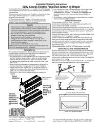
Installation/Operating <strong>Instructions</strong><br />
220 V <strong>Revelation</strong> Video Projector <strong>Mount</strong> by <strong>Draper</strong><br />
These Installation/Operating <strong>Instructions</strong> are available in the official language<br />
of the country where you purchase the product. Please contact your<br />
distributor to request a copy.<br />
Vous pourriez demander les instructions d’installation et d’opération traduises<br />
dans la langue offi cielle du pays ou vous achetez le produit. Veuillez<br />
demander à votre distributeur.<br />
Die Gebrauchsanweisung für Installation und Konstruktion sind in der<br />
offiziellen Sprache des Landes, indem Sie das Produkt gekauft haben,<br />
vorhanden. Fragen Sie die jeweilige Verkaufs-Abteilung.<br />
Caution<br />
➀ Read instructions completely before proceeding.<br />
➁ Follow instructions carefully. Installation contrary to instructions<br />
invalidates warranty.<br />
➂ Take great care when handling both fi rst surface mirrors. They will<br />
usually come covered with a protective fi lm. Remove this film after<br />
installation and prior to projecting images. If cleaning is nec es sary, do<br />
so very lightly with glass cleaner and a soft, lint free cloth.<br />
➃ Do not obstruct operation of door with fi ngers or any object. Serious<br />
injury or damage could result.<br />
➄ The <strong>Revelation</strong> is not designed to act as a structural support of ceiling<br />
framing. However, the trim frame is designed to support ceiling T-grid,<br />
tiles and drywall. Equip ment should not be al lowed to rest on door<br />
at any time.<br />
➅ Entire bottom of unit must be unobstructed to permit proper op er a tion.<br />
Suffi cient clearance (432mm minimum) must be allowed below door.<br />
➆ A minimum clearance of 458mm is required above ceiling level for<br />
model B or 347mm for Model A, if Environmental Airspace Housing is<br />
used. If no Environmental Airspace Housing, the minimum clear ance is<br />
331mm for both models.<br />
➇ Unit must be installed level (use a carpenter’s level).<br />
➈ Unit operates on 220 V a.c. 60 hz. current.<br />
Note: Unit has been thoroughly inspected and tested at factory and found<br />
to be operating properly prior to shipment.<br />
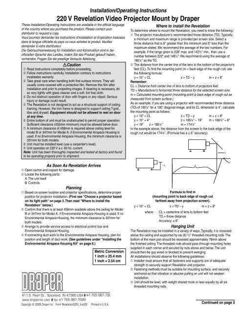
Where to install the <strong>Revelation</strong><br />
To determine where to mount the <strong>Revelation</strong>, you need to know the fol low ing:<br />
➀ The projector manufacturer’s rec om mend ed throw distance (TD). Typically,<br />
a minimum and maximum range is provided per screen size. Select a<br />
throw distance that is 6" greater than the minimum and 6" less than the<br />
maximum stated. We recommend the average of the two numbers. For<br />
example, if the range given is 228" max. and 142½" min., then use a<br />
number between 222" and 148½". We rec om mend using the average of<br />
185¼" as the TD.<br />
➁ The distance from the center line of the lens to the bottom of the projector’s<br />
feet (CL). To find the mounting point (m = back edge of the rough cut) use<br />
the fol low ing formula:<br />
y = 15" + CL z = TD – y m = z + 8"<br />
Remember:<br />
CL = Distance from center line of lens to bottom of pro jec tors feet.<br />
TD = Manufacturer’s hor i zon tal throw dis tance for the se lect ed screen size.<br />
m = Calculated mounting point (mounting point is back edge of rough cut as<br />
measured from screen surface.)<br />
As an example, if you are using a pro jec tor with recommended throw distance<br />
(TD) of 185¼" for a 100" diagonal image, and its CL di men sion is 4", calculate<br />
the mounting point as follows:<br />
y = 15" + CL z = TD – y m = z + 8"<br />
y = 15" + 4" z = 185¼" – 19" m = 166¼" + 8"<br />
y = 19" z = 166¼" m = 174¼"<br />
In the example above, the distance from the screen to the back edge of the<br />
rough cut would be 174¼". (Formula has a ± 6" accuracy).<br />
y<br />
As Soon As <strong>Revelation</strong> Arrives<br />
➀ Open carton and inspect for damage.<br />
➁ Locate the following parts:<br />
A. The unit itself<br />
B. Controls<br />
Planning<br />
➀ Based on screen location and projector specifi cations, determine proper<br />
position for projector installation. (First see "Choose a pro jec tor based<br />
on its light path" on page 3. Then read "Where to install the<br />
<strong>Revelation</strong>" below.)<br />
➁ Confi rm that there is at least 458mm available above the ceiling for Model<br />
B or 347mm for Model A, if Environmental Airspace Housing is used. If no<br />
Environmental Airspace Housing, the minimum clear ance is 331mm for<br />
both models.<br />
➂ Arrange to provide service access to electrical control box and<br />
Environmental Airspace Housing.<br />
➃ If connecting duct work to the Environmental Airspace Housing, plan for<br />
position and length of duct work. (See guidelines under "Installing the<br />
Environmental Airspace Housing Kit" on page 6.)<br />
Metric Conversion<br />
1 inch = 25.4 mm<br />
1 inch = 2.54 cm<br />
m<br />
= C L z<br />
Formula to find m<br />
(mounting point is back edge of rough cut<br />
farthest away from projection screen).<br />
y = 15" + CL z = TD – y m = z + 8"<br />
where: CL = centerline of lens to bottom feet<br />
TD = throw distance<br />
Accuracy: ± 6"<br />
Hanging Unit<br />
The <strong>Revelation</strong> may be installed in a variety of ways. Typically, it is re cessed<br />
above the ceiling and supported by six (6) 3 /8" threaded mount ing rods. The<br />
bottom of the main pan should be recessed ap prox i mate ly 76mm above<br />
the finished ceiling. The threaded rods should pass through mount ing holes<br />
supplied in each corner and secured by nuts above and below. The unit<br />
should then be guy wired or blocked to prevent swing ing.<br />
All installations should observe the following guidelines:<br />
➀ Installer must ensure that all fasteners and supports are of ad e quate<br />
strength to securely support <strong>Revelation</strong> and pro jec tor.<br />
➁ Fastening methods must be suitable for mounting surface, and se cure ly<br />
anchored so that vibration or abusive pulling on unit will not weaken<br />
installation.<br />
➂ Unit should be level, with weight shared more or less equally by all six<br />
threaded mounting rods.<br />
Copyright © 2009 <strong>Draper</strong> Inc. Form <strong>Revelation</strong>220V_Inst09<br />
Print ed in U.S.A.<br />
Continued on page 2
220 V <strong>Revelation</strong> by <strong>Draper</strong> Page 2 of 8<br />
➃ Bottom of unit must be unobstructed after installation. 432mm minimum<br />
clearance is required below the door.<br />
➄ Access should be provided to electrical control box in case service is<br />
required.<br />
➅ Do not use unit to support adjacent light fi xtures, etc.<br />
➆ Do not complete the ceiling below unit until electrical connections have<br />
been completed and unit has been operated successfully.<br />
➇ We recommend that safety cables be attached to the <strong>Revelation</strong> for<br />
added security (a sound in stal la tion practice with overhead equip ment).<br />
Electrical Connections<br />
Unit operates on 220 V a.c., 60 Hz. current.<br />
Opening the access cover on the electrical control box exposes ter mi nals<br />
for field con nec tions. Unit is shipped with internal wiring complete. Wire for<br />
con nect ing unit to switch(es) and to power supply should be fur nished by<br />
elec tri cian. Con nec tions should be made in accordance with wiring diagram<br />
on page 5, and wiring should com ply with national and local elec tri cal codes.<br />
All op er at ing switch es should be “off” before power is connected.<br />
Operation<br />
When unit is fi rst operated, be cautious! If door does not begin to open<br />
momentarily when switch is fl ipped “down”, return switch to “off” and free door<br />
and/or recheck electrical con nec tions before pro ceed ing. Cycle door down<br />
and up several times to confi rm sat is fac to ry operation.<br />
Single Station Control (CE Approved)—Moving 3-position switch to “down”<br />
position will start door down. Moving switch to “up” will start door up. When<br />
door is fully down or fully up, it will au to mat i cal ly be stopped by factory set<br />
limit switch es. When ev er switch is placed in center “off” position, op er a tion will<br />
stop.<br />
Multiple Station Control—Each switching station has a three-button switch<br />
with “up”, “down”, and “off” buttons. Door starts up or down when ap pro pri ate<br />
button is pressed, and may be stopped by pressing “off” button. Factory set<br />
limit switches stop door automatically when door is fully up or fully down.<br />
Key Operated Switch—If ordered, a single station, key-operated three position<br />
(up/off/down) switch is available for this unit.<br />
Video Interface Control (VIC12, VIC12 Modified)—This optional control<br />
device allows the <strong>Revelation</strong> switch to control the operation of a <strong>Draper</strong><br />
mo tor ized pro jec tion screen via relay.<br />
Infrared or Radio Frequency Remote Control (CE Approved)—A three-button<br />
trans mit ter is provided, with “up”, “down”, and “stop” buttons. Door starts<br />
up or down when appropriate button is pressed, and may be stopped by<br />
pressing “off” button. Factory set limit switches stop door automatically when<br />
door is fully up or fully down.<br />
Installing Projector<br />
The <strong>Revelation</strong> has a grounded 220 V a.c., 60Hz outlet for pro jec tor power<br />
sup ply. Power is supplied to this outlet at all times.<br />
Holes are provided for power and control wiring.<br />
Install a projector with the capability to invert its image.<br />
Place the projector into the sliding inner pan so that the center of the projector<br />
lens is aligned L to R with the center of the upper mirror. Position the projector<br />
lens as close as possible to the upper mirror without the refl ected light path<br />
striking any part of the projector. An extension plate is provided if the feet<br />
of your projector rest inside the opening of the inner pan. The extension<br />
is de signed to support the front legs of your projector and the folded up edge<br />
can be used as a stop to help re po si tion the projector when re moved. Adhere<br />
the ex ten sion plate only after you have adjusted the image and marked the<br />
position of the plate.<br />
Establish exact place ment through trial and error using the various ad just -<br />
ments integrated through out the design of the <strong>Revelation</strong>. The upper mirror<br />
can be moved up one inch to ac com mo date taller pro jec tors. Make the neces-<br />
sary connections and plug the power cord of the pro jec tor into the receptacle<br />
provided in the electrical chas sis. Power to the <strong>Revelation</strong> should be turned<br />
off any time electrical connections or mechanical ad just ments are made<br />
to the <strong>Revelation</strong>! Cycle the mir rored door down to the low ered position. You<br />
are now ready to move on to ad just ing the image to the screen.<br />
Adjusting Image<br />
First, use your pro jec tor’s op er at ing manual to establish proper ori en ta tion of<br />
the image and adjust the lens position to achieve the desired image width and<br />
location.<br />
Next, use the <strong>Revelation</strong>'s adjustments to adjust the height of the image on<br />
the screen.<br />
The <strong>Revelation</strong> has two adjustments:<br />
➀ Always start by sliding the inner pan which holds the projector either backward<br />
or forward depending on desired location of image. Sliding the inner<br />
pan towards the projection screen will change where the image strikes the<br />
mirror on the door, and lower the pro ject ed image. Inner pan has a travel<br />
range of ap prox i mate ly 8".<br />
➁ Opening the mirrored door even further into the room will lower the<br />
projected image. The limit switch is factory set to let the door open into<br />
the room at a 45° angle. The door can open approximately 10° farther<br />
by changing the limit switch’s position. You can also tip the front of the<br />
projector up toward the first mirror. This adjustment allows the image to be<br />
projected farther down from the ceiling, but still introduces keystone into<br />
the image. This adjustment offers the same adjustment feature as opening<br />
the mirrored door up farther into the room without adjusting the mirrored<br />
door's limit switches.<br />
Adjust the door only if your projector is equipped with keystone cor rec tion or a<br />
certain amount of keystoning can be tolerated.<br />
To adjust the limit switch of the door:<br />
TOOLS: screwdriver/Allen wrench ( 3 /16"); electronic level or protractor or other<br />
tool to measure angles.<br />
Turn the unit on and open the door to its factory set position. Record the angle<br />
measurement.<br />
Caution: Any adjustments to the limit switches should be done with the<br />
power to the <strong>Revelation</strong> turned off!<br />
Locate the two limit switch brackets at the edge of the top mirror on the motor<br />
side of the pan. The top bracket controls the down ward travel limit of the door<br />
and adjustments are made to this bracket. Note and mark current location of<br />
limit switch bracket. The bottom limit switch bracket is set at the factory for<br />
proper closure alignment and should not need adjusting.<br />
Use a 3 /16" Allen wrench to loosen the two screws on the limit switch bracket<br />
and slide the bracket toward the electrical chassis. A slight adjustment to the<br />
limit switch bracket will result in a significant move ment of the door. It is recommended<br />
that the limit switch be adjusted in small incremental moves of 1 /8".<br />
Tighten the screws. Keeping hands and tools clear of the limit switch, connect<br />
the power. The door should open further. Record the new angle and check the<br />
position of the image on the screen.<br />
If the position of the image on the screen is satisfactory, close the door and<br />
make sure the screws are completely tight.<br />
If the position of the image needs adjusting, leave the door open, dis con nect<br />
the power, loosen the screws and slide the bracket toward the motor to open<br />
the door more, or slide the bracket closer to its original position.<br />
Check alignment of image and repeat adjustment procedure as nec es -<br />
sary. After all adjustments are completed, be sure to tighten all loos ened<br />
screws to inner pan and limit switch bracket!<br />
Please Note<br />
If Glass Shield is provided, see separate in struc tions (provided<br />
with Glass Shield).<br />
www.draperinc.com (765) 987-7999
220 V <strong>Revelation</strong> by <strong>Draper</strong> Page 3 of 8<br />
Securing Projector<br />
Once all adjustments to the projector and <strong>Revelation</strong> are made, the pro jec tor<br />
should be secured into place using the eight projector stand offs pro vid ed. Two<br />
of the standoffs have a removable hook and loop material to be used at the<br />
rear of the projector for ease of removing the projector. The stand offs will ensure<br />
proper re lo ca tion of the pro jec tor after periodic main te nance or repair to<br />
the projector. Just peel the adhesive backing from the bottom of the stand offs<br />
and place them around the projector as shown in the di men sion al diagram.<br />
Important: Once the adhesive is placed onto the surface of the inner pan it is<br />
very difficult to remove. It is very important to plan ahead when placing these<br />
standoffs around the projector.<br />
Choose a projector* based on its light path<br />
A light path is the projector’s spread of light and its relationship to the centerline<br />
of the lens. Since the <strong>Revelation</strong> folds a light path twice (bounces the<br />
image off of two fi rst surface mirrors), it’s critical to un der stand your projector’s<br />
light path to know approximately where the image will land on the wall. Consult<br />
the projector's manufacturer to determine its light path geometry.<br />
Single lens projectors fall into one of four categories of light path ge om e try as<br />
depicted in the illustrations at right.<br />
Light Path A<br />
Single lens projectors with light path geometry “A” work well with the Rev e -<br />
la tion. Since the light is already projecting at a downward angle to the centerline,<br />
the image is projected further down on the wall resulting in a lower<br />
installation point for the projection screen. A projector with Light Path A<br />
mounted in the <strong>Revelation</strong> projects a light path similar to the same pro jec tor<br />
ceiling mounted with the centerline of its lens mount ed ap prox i mate ly 51-<br />
76mm (2"-3") below the ceiling.<br />
Light Path B<br />
Single lens projectors with light path geometry “B” will work with the Rev e -<br />
la tion within certain limitations. The upper edge of the image runs parallel<br />
to the centerline of the lens. A projector with Light Path B mount ed in the<br />
<strong>Revelation</strong> projects a light path similar to the same projector ceiling mount ed<br />
with the centerline of its lens mounted ap prox i mate ly 153-203mm (6"-8")<br />
below the ceiling. By using the built in adjustment features of the Rev e la tion,<br />
you should be able to bring the top of the image below the ceiling. Adjusting<br />
the ceiling closure door may introduce a keystone effect to the image. If your<br />
projector has a keystone correction feature you may be able to compensate<br />
for keystoning.<br />
Light Path C<br />
Single lens projectors with light path geometry “C” will work with the Rev e -<br />
la tion within certain limitations. The portion of the image above the centerline<br />
of the lens projects at a gradual angle up towards the ceiling. A projector<br />
with Light Path C mounted in the <strong>Revelation</strong> projects a light path similar to<br />
the same projector ceiling mounted with the centerline of its lens mounted<br />
approximately 153-203mm (6"-8") below the ceiling. By using the built in<br />
ad just ment features of the <strong>Revelation</strong>, you should be able to bring the top of<br />
the image below the ceiling. Adjusting the ceiling closure door may in tro duce<br />
a keystone affect to the image. If your projector has a keystone correction<br />
feature you may be able to compensate for keystoning.<br />
Light Path D<br />
Single lens projectors with light path geometry “D” will not work with the <strong>Revelation</strong>.<br />
The portion of the image above the centerline of the lens projects at<br />
too steep of an angle to be lowered below ceiling level, even with the adjustment<br />
features built into the <strong>Revelation</strong>.<br />
*Consult your projector manufacturer if in doubt about its light path ge om e try,<br />
throw distance or projector dimensions. Also, be sure your projector has the<br />
ability to invert its image.<br />
A<br />
B<br />
C<br />
D<br />
www.draperinc.com (765) 987-7999
220 V <strong>Revelation</strong> by <strong>Draper</strong> Page 4 of 8<br />
<strong>Revelation</strong> Dimensions<br />
6 <strong>Mount</strong>ing<br />
holes 9.525mm ( 3/ 8") dia.<br />
Electrical<br />
hook-up<br />
TB1<br />
252<br />
mm<br />
*4<br />
578mm<br />
*1<br />
8 Projector<br />
standoffs<br />
Lens and mirror<br />
centerline<br />
462mm<br />
972<br />
mm<br />
946<br />
mm 603<br />
mm<br />
17mm<br />
394mm<br />
Projector<br />
17mm<br />
165<br />
mm<br />
*2<br />
*3<br />
*2<br />
Model A Model B<br />
*1 232mm 475mm<br />
*2 330mm 457mm<br />
*3 864mm 1118mm<br />
*4 546mm 630mm<br />
4"<br />
51mm<br />
248<br />
mm<br />
25<br />
mm<br />
65<br />
mm<br />
Minimum rough opening<br />
597mm x 597mm<br />
Minimum clearance<br />
(Includes allowance<br />
for Environmental<br />
Airspace Housing)<br />
Models A & B-346mm<br />
m=Back edge of rough<br />
cut to screen surface<br />
m<br />
17mm<br />
603mm<br />
5mm<br />
Minimum clearance<br />
without<br />
Environmental<br />
Airspace Housing<br />
76mm 330mm<br />
Ceiling line<br />
103<br />
mm<br />
<strong>Revelation</strong> Dimensions & Data Model A Model B<br />
Overall Unit Size (HWL) 330 x 972 x 864mm 330 x 972 x 1118mm<br />
Required Space Above Ceiling* 346 x 972 x 864mm 458 x 972 x 1118mm<br />
Clearance Below Ceiling approx. 432mm approx. 432mm<br />
Rough Ceiling Opening 597 x 597mm 597 x 597mm<br />
Capacity 45 kg 45 kg<br />
Door’s Downward Travel Distance approx. 432mm approx. 432mm<br />
Travel Time 9 sec. 9 sec.<br />
Net Weight 39 kg 41 kg<br />
Shipping Weight 98 kg 100 kg<br />
Projector Space (HWL)—To fi t within parameters of inner pan.<br />
* 346mm is overall height of <strong>Revelation</strong> with Environmental Airspace Housing (330mm<br />
WITHOUT Environmental Airspace Housing).<br />
Electrical Specifications<br />
Operating Voltage<br />
Amperes<br />
Control Voltage<br />
Motor Specifications:<br />
Voltage 220 V a.c. 50–60 Hz<br />
Amps .43<br />
Torque 40 IN–lbs.<br />
220 V a.c. 50–60 Hz<br />
1 Amp**<br />
12 V a.c.<br />
* Includes allowance for Environmental Airspace Housing.<br />
** Does not include any load placed on internal outlet.<br />
U.S. patent number 6,379,012<br />
www.draperinc.com (765) 987-7999
1<br />
2<br />
3<br />
8<br />
9<br />
9<br />
6<br />
5<br />
2<br />
220 V <strong>Revelation</strong> by <strong>Draper</strong> Page 5 of 8<br />
Wiring Diagrams for <strong>Revelation</strong> without Environmental Airspace Housing<br />
Single Station Control<br />
COMPONENT SPECIFICATION<br />
SYM.<br />
BE<br />
1<br />
BK<br />
3<br />
YL<br />
5<br />
BK<br />
6<br />
C1<br />
C2<br />
CR1<br />
Capacitor 2mfd +/- 370 Vac<br />
Capacitor 100mfd 35 Vac<br />
Relay 12Vac 2PDT 230 Vac 10A<br />
2<br />
4<br />
RD<br />
7 8<br />
YL<br />
CR2<br />
D1<br />
Relay 12Vac 2PDT 230 Vac 10A<br />
Diode NTE125002B<br />
PRIMARY SIDE<br />
T1 WIRING<br />
SECONDARY SIDE<br />
F1<br />
F2<br />
F3<br />
Fuse 7 Amp AGC 250 Vac<br />
Fuse 1 Amp AGC 250 Vac<br />
Fuse 1 Amp AGC 250 Vac<br />
WALL SWITCH<br />
SPDT CENTER OFF<br />
TB 1<br />
T1 Transform 230V/12V@1Amp 50/60Hz<br />
MOTOR 220V .03hp 50hz. 200Lb-in. 1.1rpm<br />
COM<br />
UP<br />
DOWN<br />
BE<br />
RD<br />
1 2<br />
BE<br />
RD<br />
BK<br />
BK<br />
BK<br />
220 VAC SUPPLY<br />
50 - 60 HZ<br />
GND<br />
N<br />
L1<br />
3 4 5 6 7 8 9 10 11 12<br />
C2<br />
D1<br />
BK<br />
YW/GN<br />
BE<br />
RD<br />
YW<br />
SEE T1 WIRING DIAGRAM<br />
YW<br />
RD<br />
T 1<br />
YW<br />
BE<br />
BE<br />
BE<br />
BK<br />
RD<br />
C1<br />
CR 2<br />
RD<br />
CR 1<br />
UP<br />
DOWN<br />
RD<br />
BE<br />
RD<br />
BE<br />
BE<br />
BE<br />
BE<br />
YW/GN<br />
BK<br />
RD<br />
WH<br />
RD<br />
RD<br />
BE<br />
BE<br />
TB 2<br />
4 5 6 7 8 9 10<br />
YW/GN<br />
BK<br />
RD<br />
WH<br />
RD<br />
RD<br />
BE<br />
BE<br />
DOWN LIMIT SW<br />
UP LIMIT SW<br />
MOTOR<br />
WIRING DONE BY INSTALLER<br />
PROJECTOR OUTLET<br />
RD<br />
BE<br />
14 AWG<br />
YW/GN 14 AWG<br />
14 AWG<br />
RD<br />
BK<br />
RD<br />
RD<br />
RD<br />
1 2 3 4 5 6 7 8 9 10<br />
YW<br />
CB1B<br />
F3<br />
PCB 1<br />
F2<br />
F1<br />
CB1A<br />
4 3 8 7 1<br />
10<br />
BE<br />
BE<br />
BE<br />
WH<br />
BE<br />
RD<br />
14 AWG<br />
BE<br />
WH<br />
ALL WIRES 18 AWG. UNLESS OTHERWISE SPECIFIED.<br />
Low Voltage Multiple Station and Remote Control<br />
BE<br />
BK<br />
1 2 3<br />
COMPONENT SPECIFICATION<br />
BE<br />
1<br />
3<br />
YL<br />
5<br />
6<br />
SYM.<br />
C1<br />
Capacitor 2mfd +/- 370 Vac<br />
BK<br />
BK<br />
C2<br />
Capacitor 100mfd 35 Vac<br />
Aux Port for connecting additional LVC-III<br />
modules (up to six total-connect from Aux to Eye).<br />
3 Button Wall Switch<br />
DOWN - Black<br />
COM - White<br />
UP - Red<br />
Eye Port for IR Eye, RF Receiver or LED<br />
Switch. If more than one of these three is<br />
used with one LVC-III, a splitter is required.<br />
BN<br />
VIDEO INTERFACE<br />
OR<br />
CONTROL<br />
220 VAC SUPPLY<br />
50 - 60 HZ<br />
Red<br />
Brown<br />
Yellow<br />
Green<br />
White<br />
Black<br />
GND<br />
N<br />
L1<br />
RD<br />
BN<br />
YL<br />
GN<br />
WH<br />
BK<br />
Dashed wiring by Electrician<br />
Low voltage wiring by others<br />
PROJECTOR OUTLET<br />
1 2 3 4 5 6 7 8 9 10 11 12<br />
TB 1<br />
BE<br />
RD<br />
C2 YW<br />
D1<br />
BK<br />
BE<br />
YW/GN<br />
BE<br />
RD<br />
14 AWG<br />
RD 14 AWG<br />
YW/GN<br />
14 AWG<br />
BE 14 AWG<br />
YW<br />
YW<br />
YW<br />
F3<br />
RD<br />
BK<br />
RD PCB 1<br />
RD<br />
RD<br />
SEE T1 WIRING DIAGRAM<br />
RD BE<br />
T 1<br />
4 5 6 7<br />
10<br />
F2<br />
F1<br />
CB1B<br />
CB1A<br />
10 9 8 7 6 5 4 3 2 1<br />
BE<br />
BE<br />
BE<br />
WH<br />
BE<br />
RD<br />
RD<br />
2 4<br />
7 8<br />
PRIMARY SIDE<br />
SECONDARY SIDE<br />
T1 WIRING<br />
BK<br />
BK<br />
BE<br />
BE<br />
CR 1<br />
BE<br />
UP<br />
BE<br />
RD<br />
RD<br />
BE<br />
RD<br />
CR 2<br />
YW/GN<br />
TB 2<br />
BK<br />
RD<br />
DOWN<br />
BE<br />
BE<br />
WH<br />
BK<br />
RD<br />
RD<br />
RD<br />
C1<br />
BE<br />
BE<br />
BE<br />
BK<br />
BE<br />
WH<br />
ALL WIRES 18 AWG. UNLESS OTHERWISE SPECIFIED.<br />
CR1 Relay 12Vac 2PDT 230 Vac 10A<br />
YL<br />
CR2 Relay 12Vac 2PDT 230 Vac 10A<br />
D1 Diode NTE125002B<br />
F1 Fuse 7 Amp AGC 250 Vac<br />
F2 Fuse 1 Amp AGC 250 Vac<br />
F3 Fuse 1 Amp AGC 250 Vac<br />
T1 Transform 230V/12V@1Amp 50/60Hz<br />
MOTOR 220V .03hp 50hz. 200Lb-in. 1.1rpm<br />
1 2 3 4 5 6 7 8 9 10<br />
YW/GN<br />
BK<br />
MOTOR<br />
RD<br />
WH<br />
RD<br />
RD DOWN LIMIT SW<br />
BE<br />
BE UP LIMIT SW<br />
BE<br />
12 V<br />
BK<br />
www.draperinc.com (765) 987-7999
I<br />
I<br />
t<br />
I<br />
1<br />
2<br />
6<br />
9<br />
4<br />
3<br />
220 V <strong>Revelation</strong> by <strong>Draper</strong> Page 6 of 8<br />
Field Installation of Environmental Airspace Housing Kit<br />
Caution! Disconnect power from the <strong>Revelation</strong> before installing Environmental<br />
Airspace Housing.<br />
➀ Remove the covers from the electrical chassis in the <strong>Revelation</strong>.<br />
➁ Disconnect the black 14 awg. wire that runs from the T2 trans form er to<br />
the re cep ta cle in the electrical chassis.<br />
➂ Install the pre-wired current sensor using two #6-32 x 1" [10] long screws<br />
provided. (SEE FIGURE #1.)<br />
➃ Connect each wire of the pre-wired current sensor as shown by DIA-<br />
GRAM #1.<br />
➄ Install the two fan mount assemblies [5,6] to the main pan of the Rev e -<br />
la tion using the eight #10-32 x . 3 /8" [7,8] long screws provided. (SEE<br />
FIGURE #1.) Attach the long leads of the Exhaust Fan As sem bly [6] to<br />
the end with the motor and lifting mechanism.<br />
➅ Using the wire clips [11] provided, lay in the wires from the fans as<br />
shown in FIG URE #1 and con nect the fans to TB1-8 & TB1-9 as shown<br />
in DI A GRAM #1.<br />
➆ Replace the covers to the electrical chassis.<br />
➇ Apply the 25 mm wide Nylon [12,13] tape as shown in FIGURE #1.<br />
➈ Install the inner and outer plenum covers [1,2], and attach the mating<br />
end panel [3,4] as shown in FIGURE #2.<br />
➉ Fan mounting panels are designed to accept a standard 4" round duct.<br />
The exhaust fl ange is located on the motor/drive end of the Rev e la tion<br />
and the input is located at projector end of the <strong>Revelation</strong>.<br />
If duct work is connected to this unit, here are a few recommended guide lines<br />
you should keep in mind when installing the duct work:<br />
• Air supply to the Environmental Airspace Housing should be cool enough<br />
to provide adequate cooling for your projector.<br />
• Do not obstruct airfl ow through duct work. Inadequate airfl ow may result in<br />
excessive heat buildup inside the unit.<br />
• Keep duct work length as short as possible. Recommended maximum total<br />
duct length is 914 cm (input plus ex haust).<br />
• Keep the input-to-exhaust length ratio balanced and as small as possible<br />
to prevent air from being pushed into or drawn out of the room.<br />
FIGURE #1<br />
TB1<br />
Nylon tape 43" long<br />
Input<br />
fan<br />
assembly<br />
(short<br />
wires)<br />
Wire clips typ.<br />
FIGURE #2<br />
Exhaust<br />
fan<br />
assembly<br />
Outer end panel<br />
TB1 T2 F4<br />
F5<br />
1 12<br />
Projector<br />
Outer Environmental<br />
Air Space Housing<br />
cover<br />
BK<br />
BK WH BK RD<br />
1 2 3 4 5<br />
CS1<br />
T2 transformer<br />
CB1B<br />
1 10<br />
T1<br />
F3<br />
PCB1<br />
F2<br />
F1<br />
1 10<br />
CB1A<br />
Curent sensor<br />
F1 = 7 Ampere<br />
F2 = 1 Ampere<br />
F3 = 1 Ampere<br />
F4 = 4 Ampere<br />
F5 = 4 Ampere<br />
Inner Environmental<br />
Air Space Housing<br />
cover<br />
CR1<br />
CR2<br />
C1<br />
PCB1<br />
TB2<br />
1 12<br />
Motor<br />
Nylon tape 39" long<br />
Exhaust<br />
fan<br />
assembly<br />
(long<br />
wires)<br />
Inner end panel<br />
Input<br />
fan<br />
assembly<br />
DIAGRAM #1<br />
FAN<br />
(IN)<br />
FAN<br />
(OUT)<br />
220 VAC SUPPLY N<br />
50 - 60 HZ<br />
L1<br />
NOTES:<br />
1.<br />
2.<br />
BK<br />
PROJECTOR<br />
OUTLET<br />
BK<br />
1 2 3 4 5 6 7 8 9 10 11 12<br />
RD<br />
TB 1<br />
BE<br />
14 AWG<br />
14 AWG<br />
YW/GN<br />
14 AWG<br />
YW/GN<br />
RD<br />
WIRE TO BE REMOVED BEFORE INSTALLING PLENUM WIRING<br />
WIRES CONNECTED BY INSTALLER<br />
4 TURNS<br />
14 AWG<br />
3. ALL WIRES 18 AWG. UNLESS OTHERWISE SPECIFIED.<br />
RD<br />
BE<br />
BE<br />
C2<br />
D1<br />
BE<br />
WH<br />
CS 1<br />
1 2<br />
BK<br />
BK<br />
BK<br />
BK<br />
RD<br />
BK<br />
3 4 5<br />
3 4 5<br />
7 8<br />
10<br />
CB1B<br />
F3<br />
PCB 1<br />
F2<br />
F1<br />
5 2 1<br />
10 9 8 7 6<br />
CB1A<br />
BE<br />
BE<br />
BE<br />
BK<br />
ENVIRONMENTAL AIRSPACE HOUSING<br />
INSTALLATION PART LIST<br />
ITEM# DESCRIPTION<br />
QTY<br />
1 INNER ENVIRONMENTAL AIRSPACE HOUSING COVER 1<br />
2 OUTER ENVIRONMENTAL AIRSPACE HOUSING COVER 1<br />
3 INNER END PANEL 1<br />
4 OUTER END PANEL 1<br />
5 INPUT FAN MOUNT ASSEMBLY 1<br />
6 EXHAUST FAN MOUNT ASSEMBLY 1<br />
7 SCREW #10–32 X .375" (9.525mm) 8<br />
HEX HD TYPE "F" ZINC<br />
8 WASHER, #10 ZINC INTERNAL LOCK 8<br />
9 PRE-WIRED CURRENT SENSOR 1<br />
10 SCREW #6–32 X 1" (25.4mm) 2<br />
LONG PHIL PAN HD ZINC<br />
11 CLIP ADHESIVE BACKED CORD 7<br />
6.35mm HOLD ING DIA.<br />
12 991 mm LONG 25.4mm WIDE X .762mm 1<br />
THICK NYLON TAPE<br />
13 1092mm LONG 25.4mm WIDE X .762mm 1<br />
THICK NYLON TAPE<br />
TOOLS NEEDED<br />
MED POINT PHILLIP SCREWDRIVER<br />
1<br />
/8" FLAT BLADE SCREW DRIVER<br />
3<br />
/8" WRENCH<br />
www.draperinc.com (765) 987-7999
I<br />
I<br />
t<br />
I<br />
YW/GN<br />
1<br />
I<br />
I<br />
t<br />
I<br />
1<br />
7<br />
8<br />
1<br />
1<br />
7<br />
8<br />
220 V <strong>Revelation</strong> by <strong>Draper</strong> Page 7 of 8<br />
The <strong>Revelation</strong> Environmental Airspace Housing features a unique design<br />
that allows easy access to virtually anywhere inside the unit. Access is<br />
achieved by removing either end panel. End panels feature captive screw<br />
assemblies so no hard ware can be lost or misplaced. Once the end panel<br />
is removed, slide the Environmental Airspace Housing toward the center of<br />
the unit. Service and main te nance is made simpler due to the accessibility<br />
provided by this unique Environmental Airspace Housing design.<br />
Each Environmental Airspace Housing also features a ventilation system<br />
designed to maintain a suitable operating environment for your projector. An<br />
Environmental Airspace Housing Operating <strong>Instructions</strong><br />
integrated current sensor in the <strong>Revelation</strong> circuitry turns on the fans anytime<br />
the projector is op er at ing and circulates fresh air through the unit. Two 4" duct<br />
flanges are located on the ends of the Environmental Airspace Housing for<br />
installation of duct work for di rect ing the airflow to and from the unit. The input<br />
flange is located on the motor/drive end of the <strong>Revelation</strong> and the exhaust<br />
is located at projector end of the revelation. If duct work is attached to the<br />
Rev e la tion, follow guidelines in Environmental Airspace Housing Installation<br />
<strong>Instructions</strong> on page 6.<br />
Wiring Diagrams for <strong>Revelation</strong> with Environmental Airspace Housing<br />
Single Station Control<br />
SYM<br />
COMPONENT SPECIFICATIONS<br />
WALL SWITCH<br />
SPDT CENTER OFF<br />
COM<br />
UP<br />
DOWN<br />
BE<br />
RD<br />
BK<br />
2<br />
BE<br />
1 3<br />
BK<br />
YL<br />
5 6<br />
BK<br />
C1<br />
C2<br />
CR1<br />
Capacitor 2mfd +/- 370 Vac<br />
Capacitor 100mfd 35 Vac<br />
Relay, Coil-12Vac, 2PDT 230Vac 10Amp<br />
2<br />
4<br />
RD<br />
7 8<br />
YL<br />
CR2<br />
CS1<br />
Relay, Coil-12Vac, 2PDT 230Vac 10Amp<br />
Current sensor 230Vac 2-20Amp SASC<br />
1<br />
TB 1<br />
BE<br />
PRIMARY SIDE<br />
BK<br />
T1 WIRING<br />
BK<br />
SECONDARY SIDE<br />
D1 Diode NTE125002B<br />
F1 Fuse 7Amp AGC 250 Vac<br />
F2 Fuse 1Amp AGC 250 Vac<br />
F3 Fuse 1Amp AGC 250 Vac<br />
FAN 220Vac 8Watt 50cfm 1600rpm<br />
T1 Transform 220V/12V@1Amp 50/60Hz<br />
MOTOR 220V .03hp 50-60hz. 200Lb-in. 1.1rpm<br />
RD<br />
3 4<br />
C2 YW<br />
D1<br />
SEE T1 WIRING DIAGRAM<br />
BE<br />
CR 1<br />
UP<br />
BE<br />
BE<br />
BE<br />
YW/GN<br />
TB 2<br />
FAN<br />
(IN)<br />
220 VAC SUPPLY<br />
50 - 60 HZ<br />
FAN<br />
(OUT)<br />
GND<br />
N<br />
L1<br />
BK<br />
WIRING DONE BY INSTALLER<br />
PROJECTOR OUTLET<br />
BK<br />
5 6 7 8 9 10 11 12<br />
RD<br />
BE<br />
14 AWG<br />
BK<br />
RD<br />
BE<br />
BE<br />
RD<br />
YW/GN<br />
YW/GN<br />
14 AWG<br />
14 AWG<br />
RD<br />
RD<br />
BK<br />
BK<br />
RD<br />
RD<br />
2 3 4 5 6<br />
7 8 9 10<br />
YW<br />
CB1B<br />
RD<br />
YW<br />
T 1<br />
F3<br />
PCB 1<br />
F2<br />
F1<br />
YW<br />
BE<br />
CB1A<br />
4 3 2<br />
6 5<br />
10 9<br />
BE<br />
BE<br />
BE<br />
WH<br />
BE<br />
BE<br />
RD<br />
RD<br />
BE<br />
BK<br />
C1<br />
CR 2<br />
RD<br />
DOWN<br />
RD<br />
BE<br />
BE<br />
RD<br />
BE<br />
WH<br />
BK<br />
RD<br />
WH<br />
RD<br />
RD<br />
BE<br />
BE<br />
BE<br />
BK<br />
1 2 3 4 5 6 7 8 9 10<br />
YW/GN<br />
BK<br />
RD<br />
WH<br />
RD<br />
RD<br />
BE<br />
BE<br />
DOWN LIMIT SW<br />
UP LIMIT SW<br />
MOTOR<br />
14 AWG<br />
BE<br />
BK<br />
RD<br />
4 TURNS<br />
14 AWG<br />
1 2<br />
3<br />
4 5<br />
CS 1<br />
ALL WIRES 18 AWG. UNLESS OTHERWISE SPECIFIED.<br />
Low Voltage Multiple Station and Remote Control<br />
SYM<br />
COMPONENT SPECIFICATIONS<br />
C1<br />
Capacitor 2mfd +/- 370 Vac<br />
BE<br />
1 3<br />
BK<br />
YL<br />
5 6<br />
BK<br />
C2<br />
CR1<br />
CR2<br />
Capacitor 100mfd 35 Vac<br />
Relay, Coil-12Vac, 2PDT 230Vac 10Amp<br />
Relay, Coil-12Vac, 2PDT 230Vac 10Amp<br />
Red<br />
Brown<br />
Yellow<br />
Green<br />
White<br />
Black<br />
RD<br />
BN<br />
2 4<br />
PRIMARY SIDE<br />
RD<br />
T1 WIRING<br />
YL<br />
7 8<br />
SECONDARY SIDE<br />
CS1<br />
D1<br />
F1<br />
F2<br />
F3<br />
FAN<br />
T1<br />
Current sensor 230Vac 2-20Amp SASC<br />
Diode NTE125002B<br />
Fuse 7Amp AGC 250 Vac<br />
Fuse 1Amp AGC 250 Vac<br />
Fuse 1Amp AGC 250 Vac<br />
220Vac 8Watt 50cfm 1600rpm<br />
Transform 220V/12V@1Amp 50/60Hz<br />
YL<br />
Eye Port for IR Eye, RF Receiver or LED<br />
Switch. If more than one of these three is<br />
GN<br />
used with one LVC-III, a splitter is required.<br />
3 Button Wall Switch<br />
DOWN - Black<br />
WH<br />
COM - White<br />
UP - Red<br />
BK<br />
Aux Port for connecting additional LVC-III<br />
modules (up to six total-connect from Aux to Eye)<br />
1<br />
2<br />
3<br />
4<br />
TB 1<br />
BE<br />
RD<br />
C2<br />
D1<br />
YW<br />
SEE T1 WIRING DIAGRAM<br />
BE<br />
BK<br />
CR 1<br />
UP<br />
BK<br />
BE<br />
BE<br />
BE<br />
MOTOR 220V .03hp 50-60hz. 200Lb-in. 1.1rpm<br />
YW/GN<br />
TB 2<br />
VIDEO INTERFACE<br />
CONTROL<br />
FAN<br />
(IN)<br />
220 VAC SUPPLY<br />
50 - 60 HZ<br />
BN<br />
OR<br />
FAN<br />
(OUT)<br />
GND<br />
N<br />
L1<br />
BK<br />
BK<br />
Dashed wiring by electrician<br />
Low voltage wiring by others<br />
PROJECTOR OUTLET<br />
5<br />
6<br />
7<br />
8 9 10<br />
11 12<br />
RD<br />
BE<br />
14 AWG<br />
14 AWG<br />
RD<br />
RD<br />
BE<br />
BE<br />
BK<br />
YW/GN<br />
14 AWG<br />
RD<br />
RD<br />
BK<br />
BK<br />
RD<br />
RD<br />
2 3 4 5 6<br />
7 8 9 10<br />
YW<br />
CB1B<br />
YW<br />
RD<br />
T 1<br />
F3<br />
PCB 1<br />
F2<br />
F1<br />
YW<br />
BE<br />
CB1A<br />
4 3 2<br />
6 5<br />
10 9<br />
BE<br />
BE<br />
BE<br />
WH<br />
BE<br />
BE<br />
RD<br />
RD<br />
BE<br />
CR 2<br />
DOWN<br />
BK<br />
RD<br />
C1<br />
RD<br />
BE<br />
BE<br />
RD<br />
BE<br />
WH<br />
BK<br />
RD<br />
WH<br />
RD<br />
RD<br />
BE<br />
BE<br />
BE<br />
BK<br />
1 2 3 4 5 6 7 8 9 10<br />
YW/GN<br />
BK<br />
RD<br />
WH<br />
RD<br />
RD<br />
BE<br />
BE<br />
BE<br />
BK<br />
MOTOR<br />
DOWN LIMIT SW<br />
UP LIMIT SW<br />
12 V<br />
14 AWG<br />
BE<br />
BK<br />
RD<br />
4 TURNS<br />
14 AWG<br />
CS 1<br />
1 2 3 4 5<br />
ALL WIRES 18 AWG. UNLESS OTHERWISE SPECIFIED.<br />
www.draperinc.com (765) 987-7999
220 V <strong>Revelation</strong> by <strong>Draper</strong> Page 8 of 8<br />
VIC12 Kit Installation <strong>Instructions</strong><br />
The VIC 12 KIT includes all the components necessary for the VIC 12 to work<br />
with the <strong>Revelation</strong>. Follow these steps to install the components in this KIT.<br />
➀ Close the door to the <strong>Revelation</strong>.<br />
FIGURE #1<br />
➁<br />
DISCONNECT POWER TO THE REVELATION.<br />
➂<br />
➃<br />
➄<br />
Remove the covers from the electrical enclosure.<br />
Attach the pre-wired limit switch [1] to the shaft mounting bracket which<br />
is closest to the motor as shown in FIGURE #1. Using the<br />
#6–32 x 1" [2] long screws and #6 lock washers [2] provided.<br />
Run the wires through the open grommet in the end of the electrical<br />
enclosure that is toward the motor as shown in FIGURE #1 and connect<br />
them as fol lows:<br />
Connect the black wire to screw #1 of TB2<br />
CR 1<br />
CR 2<br />
C 1<br />
TB 2<br />
12345678 910<br />
Black<br />
Blue<br />
Motor<br />
Pre-wired limit switch<br />
12V Actuator lever<br />
Connect the blue wire to screw #2 of TB2. (Be sure that wires do not<br />
interfere with moving linkage or the sliding inner pan)<br />
➅<br />
➆<br />
Put the 12V ACTIVATOR LEVER [3] onto the shaft as shown in Figure<br />
#2. The 12V ACTUATOR LEVER will need to be spread out before it will<br />
fit onto the shaft. The door to the <strong>Revelation</strong> must be closed before going<br />
on to step #7<br />
Position the 12V ACTUATOR LEVER by rotating it into the limit switch<br />
until the limit switch clicks and secure the lever onto the shaft using the<br />
#10-32 screw [4] and lock washer [5] supplied with the lever. (Be sure<br />
that the screw on the lever is tightened so that the lever does not twist on<br />
the shaft.)<br />
FIGURE #2<br />
12V actuator lever<br />
➇<br />
➈<br />
➉<br />
After the VIC 12 [7] is installed with the screen, run the wiring to the<br />
<strong>Revelation</strong> using the cord strain relief [6] and connect to TB1 as shown<br />
in the Rev e la tion wiring diagram.<br />
Put the covers back on to the electrical enclosure.<br />
Reconnect power to the revelation.<br />
Rotate lever<br />
until the limit<br />
switch clicks.<br />
Tighten lever<br />
onto shaft.<br />
Pre-wired<br />
limit switch<br />
VIC 12 OR VIC 12 MODIFIED INSTALLATION PART LIST<br />
ITEM # DESCRIPTION QTY<br />
1 PRE-WIRED LIMIT SWITCH 1<br />
2 SCREW #6–32 X 1"(25.4mm) LONG 2<br />
PHIL PAN HD W/ EXT LOCK WASHER<br />
3 12v ACTUATOR LEVER 1<br />
4 SCREW #10–32 X 3/8" (9.525mm) LONG SHCS 1<br />
5 WASHER #10–.190" I.D. X .375" (9.525mm) O.D. 1<br />
ZINC INTERNAL TOOTH<br />
6 FITTING CORD CRIMP STRAIN RELIEF 1<br />
7 VIC 12 OR VIC 12 MODIFIED 1<br />
TOOLS NEEDED<br />
MED POINT PHILLIP SCREW DRIVER<br />
I<br />
/8" FLAT BLADE SCREW DRIVER<br />
3<br />
/16" ALLEN WRENCH<br />
www.draperinc.com (765) 987-7999